
Abstract
Steam turbines are used to generate thermal power in electric power plants. They are important industrial equipment that support societal infrastructure. The stable operation of steam turbines is necessary to maintain long-term electrical power supply. However, low-frequency vibration, which is referred to as steam-whirl-induced vibration, is a self-excited vibration that can damage turbines and hinders stable operation. Therefore, a prediction model and stable margin for steam-whirl-induced vibration in steam turbines should be developed. In this study, we propose a method for modeling steam-whirl-induced vibration using closed-loop system identification. This method directly creates a vibration model from the rotor displacement data. The gain, damping, and natural frequency of the vibration were calculated using this model. Moreover, an equation for the relationship between the damping and load was derived using the model, and the stable margin for increasing the load was estimated. Steam-whirl-induced vibration was modeled using the proposed method for the displacement data obtained from an actual steam turbine. The characteristics of the model are in good agreement with the experimental results, indicating the feasibility of using the model to predict steam-whirl-induced vibration.
Keywords
Introduction
Electric power generation plants play a vital role in daily life because electric power is indispensable for sustaining existing societal infrastructure. In recent decades, power generation using renewable energy has been promoted considering environmental conservation. However, thermal power plants still generate a major share of global electricity (OpenPR.com., 2018). According to the statistical data for 2021 (Renewable Energy Institute, 2021), approximately 55% of the world’s electricity is generated by thermal power plants. In a thermal power plant, heated fuel releases thermal energy, which is transferred to water to generate steam. A steam turbine converts steam energy into electric power. The rotor of the turbine is rotated by steam and the rotational energy is converted into electric power by a generator connected to the end of the rotor. One of the most important design aspects of steam turbines is the stable operation of their rotors. Long-term stable operation of steam turbines is essential for ensuring stable power supply. The rotor is affected by structural and fluid dynamics. In previous studies, rotor stability was evaluated through rotor dynamics analysis (Childs, 1993, Vance, 1988).
Rotors in steam turbines experience low-frequency vibration due to mechanical forces and steam pressure (Kanki et al., 1998). Low-frequency vibration is a unique problem of steam turbines and is called steam-whirl-induced vibration (Hirano et al., 2005, Hirano et al., 2008, Gao et al., 2009). The amplitude of steam-whirl-induced vibration increases with the load on the rotor. Thus, to maintain stable operation of a steam turbine, the amplitude of the steam-whirl-induced vibration should be estimated to determine the load limit. In previous studies, the characteristics of steam-whirl-induced vibration were analyzed using computational fluid dynamics (CFD). Furthermore, vibrational characteristics were examined using numerical calculations based on CFD (Kramer, 1993, Schettel and Nordmann, 2004, Bachschmid et al., 2008, Pollman et al., 1978) and vibration analysis based on experimental data (Hisa et al., 1985, Bachschmid et al., 2006, Kubiak et al., 2007, Pennacchi and Vania, 2011). However, these methods have several drawbacks for practical applications. The time required to obtain accurate results via numerical calculations is considerably high for complex rotating machinery. The evaluation of experimental data requires less time compared with numerical calculations. However, these results may not provide a systematic solution for rotating machinery.
According to the displacement data obtained from a steam turbine, steam-whirl-induced vibration is the forced vibration that appears when the load is lower than the threshold for self-excited vibration (Kanki et al., 1998). Vibration can be modeled as a transfer function using displacement data. A linear model can be applied to rotor dynamics by using a transfer matrix under certain conditions (Childs, 1993). In previous studies, steam-turbine dynamics were modeled at a constant rotational speed using a linear model (Bachschmid et al., 2006, Bachschmid et al., 2008) and transfer function (Cloud et al., 2005, Hu and Palazzolo, 2017, Yabui et al., 2020). Based on the principles of control engineering, rotating machinery supported by a journal bearing, such as a steam turbine, can be considered a closed-loop system. The journal bearing is an analogue controller for positioning a rotor, and the rotating shaft is the control object (Utsumi, 2020, Yabui et al., 2020).
In this study, we propose a modeling method based on a closed-loop system for steam-whirl-induced vibration for application to rotating machinery. In a closed-loop system, steam-whirl-induced vibration is regarded as a perturbation of the control object, and an additional uncertainty modeling method is applied based on the framework of closed-loop system identification. The modeling method models the steam-whirl-induced vibration as a transfer function, which is directly identified using only the displacement data. The proposed method is based on a direct method of closed-loop system identification. There are other system identification methods: indirect, two-stage, and joint input-output methods (Prasad et al., 1977, Linder and Enqvist, 2017, Ase and Katayama, 2018). These methods use information from the feedback controller or the input data for the closed-loop system. However, we decided to use the direct method for system identification for two reasons: • The characteristics of journal bearings are difficult to identify accurately. The characteristics depend on the operating condition (rotating speed, load, radial clearance, and Reynolds number of oil film). Under constant conditions, the characteristics can be linearized; however, the correct coefficients in the transfer function model are difficult to identify in the actual system. • In the general rotating machineries, we can only obtain the displacement data. That is, we can obtain the output data but cannot obtain the input data in the block diagram. Therefore, we try to identify the steam-whirl-induced vibration model by using only the displacement data (output data).
This method does not require complex calculations, and the rotor displacement data can be easily measured. The vibration gain, damping ratio, and natural frequency were expressed as functions of the load. The proposed method uses gray-box modeling to evaluate vibrational characteristics.
Modeling of steam-whirl-induced vibration
Experimental system
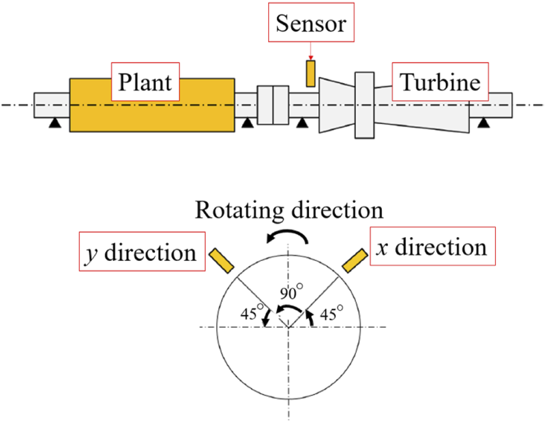
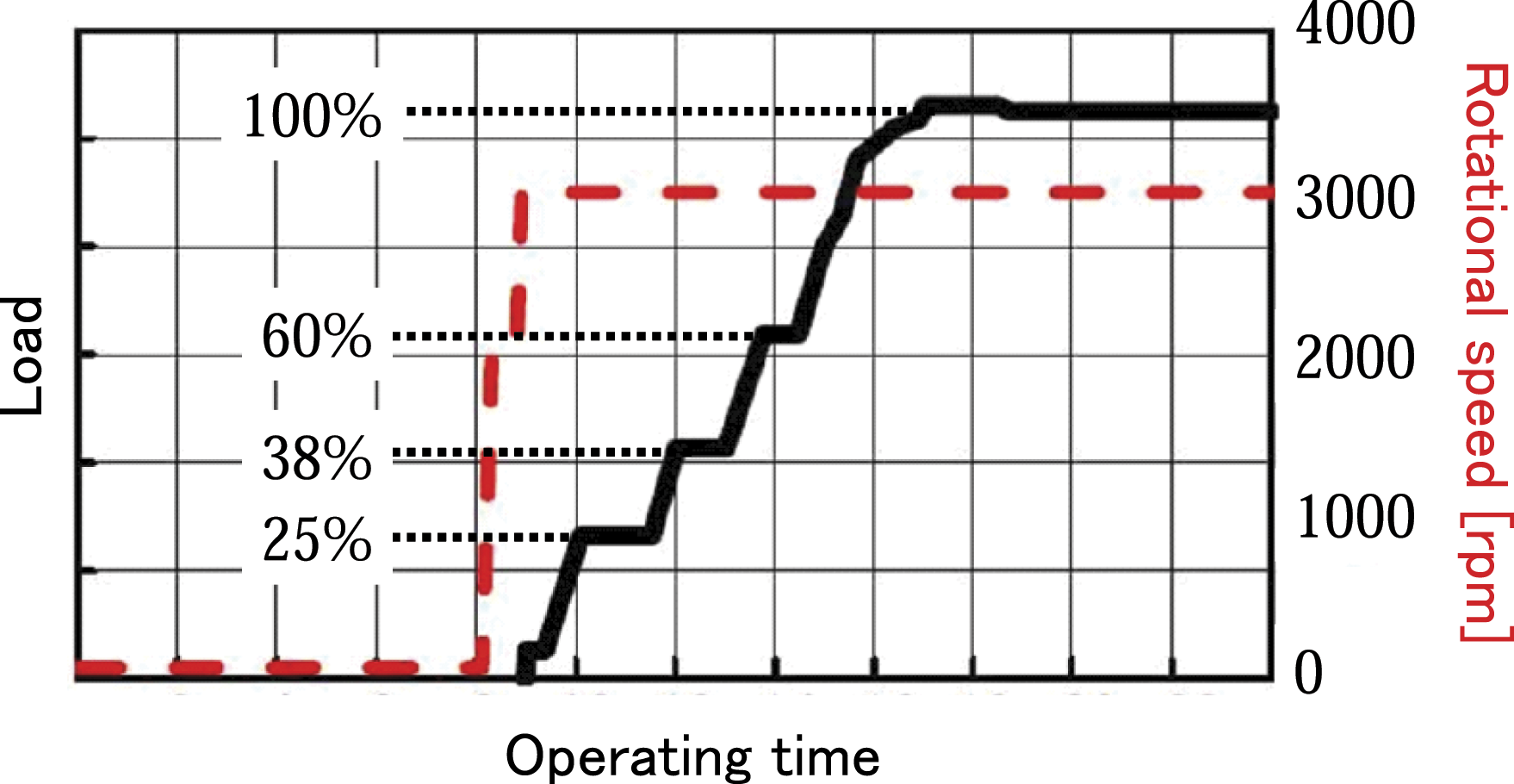
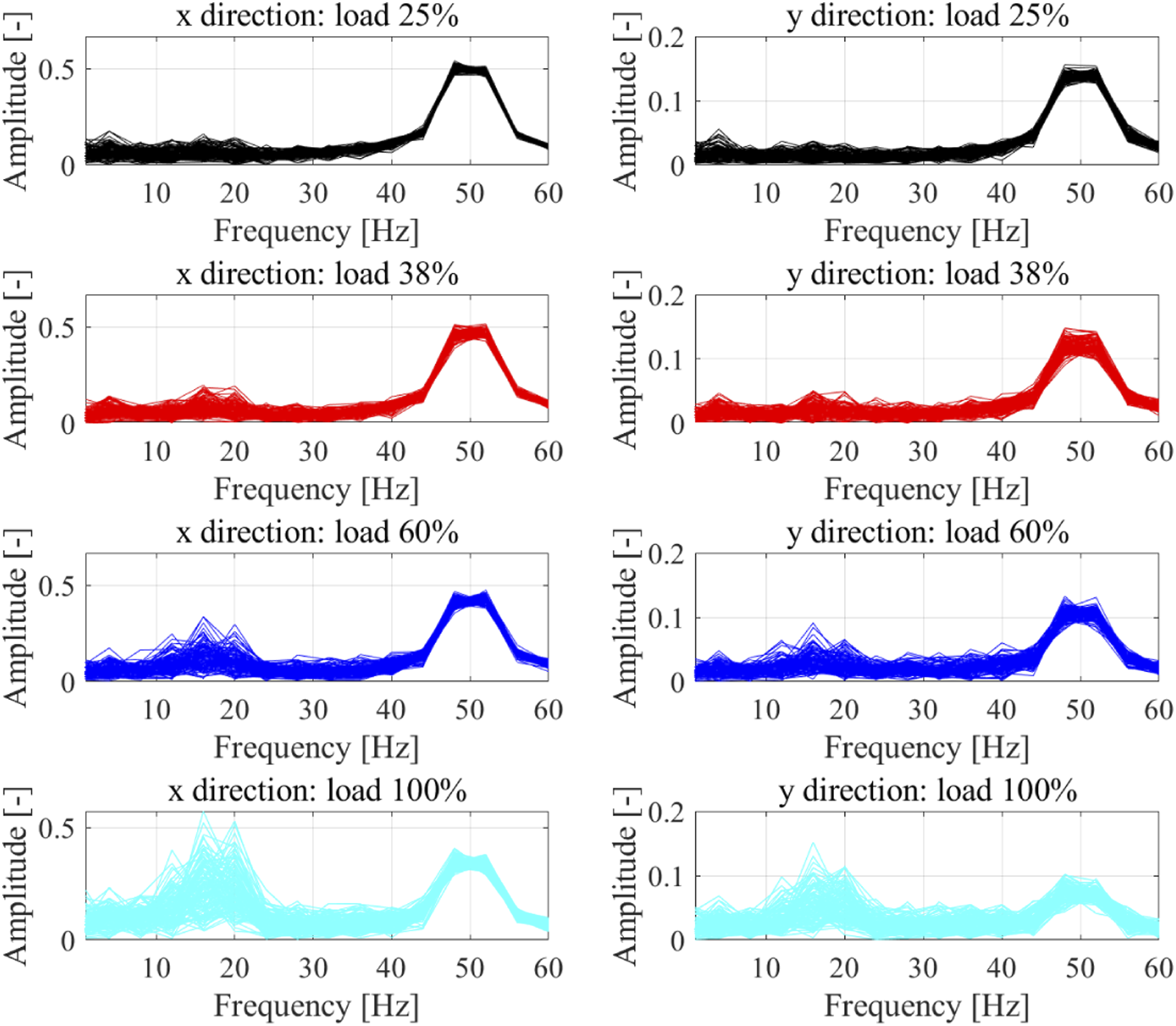
The target steam turbine used in this study is illustrated in Figure 1. The steam-whirl-induced vibration were measured using a displacement sensor, as shown in Figure 2. The measurement result depends on the mode shape of the rotating shaft. The sensor installation location is limited in the experimental system. Therefore, the location of the displacement sensors was decided to obtain sufficiently the vibration peak from the location option. The operating conditions (load and rotational speed) are illustrated in Figure 3. When the rotational speed reached 3000 rpm, the following four loading conditions were considered: 25%, 38%, 60%, and 100%. Only the load was varied during the operation of the steam turbine. The displacement data (120 sets) were measured under each loading condition at a sampling frequency of 2048 Hz for 1 s. The amplitude spectrum of the displacement is shown in Figure 4. Unbalanced vibration were observed as an amplitude peak at 50 Hz. In addition, the amplitude spectrum increased by approximately 18 Hz with the load. The fundamental cause of the vibration was determined to be the steam whirl, which increased with the load. Image of the steam turbine (OpenPR.com., 2018). Schematic of the steam turbine. Experimental condition of the steam turbine. The rotating speed was changed from 0 to 3000 rpm, and the percentage of load was changed from 0% to 100% as shown in this figure. Amplitude spectrum of displacement signal in x, y direction: The displacement signal is measured 2048 point × 120 sets. The amplitude spectrum calculated from each set is overplotted in this figure.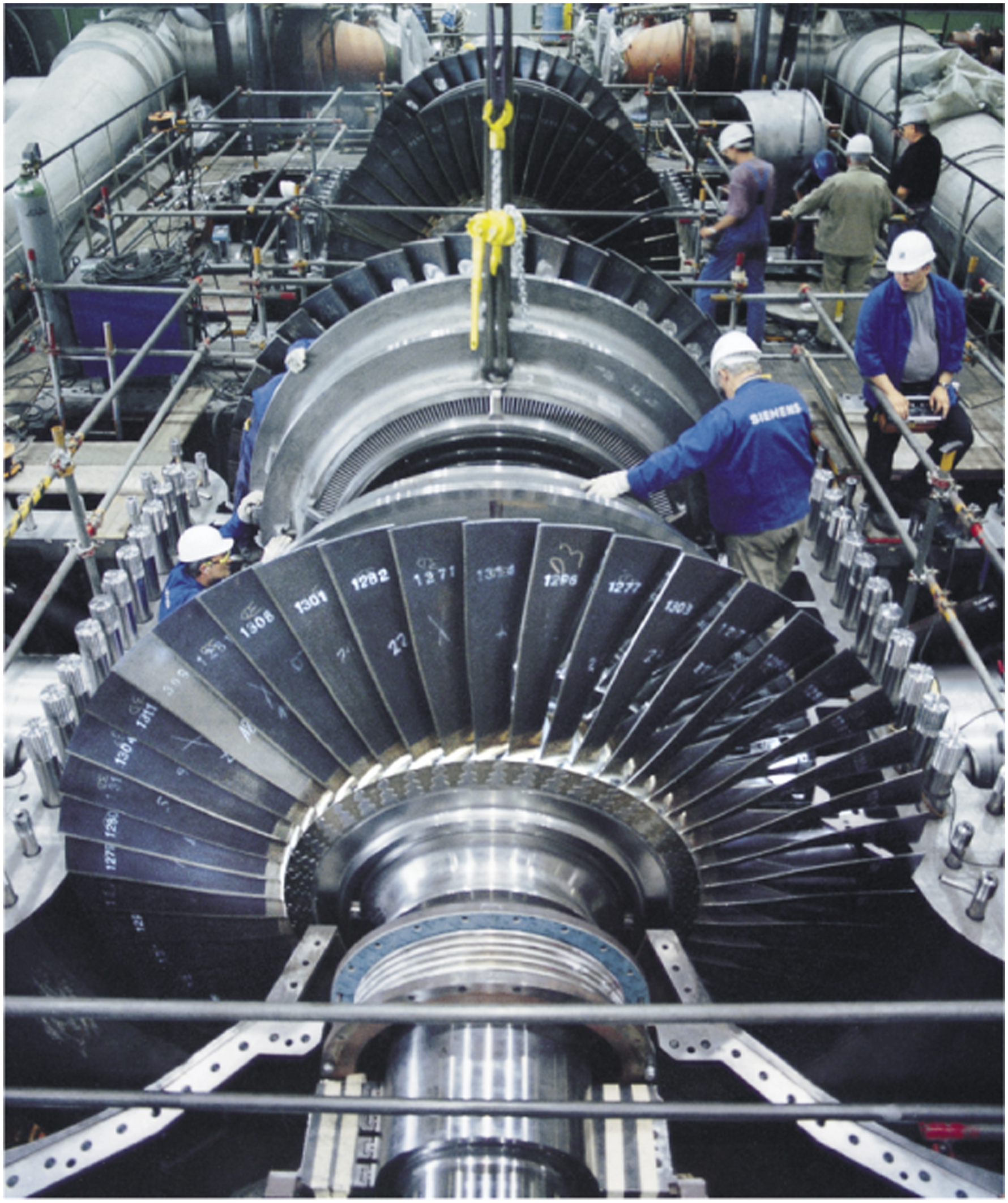
Block diagram of proposed model for steam-whirl-induced vibration
Closed-loop system identification was applied to the steam-whirl-induced vibration model. Although rotating machinery has nonlinear characteristics owing to its complex dynamics, its characteristics can be approximately linearized under certain conditions (Childs, 1993). Previous studies have proposed a linear model for the dynamics of rotating machinery (Cloud et al., 2005, Yabui et al., 2020). Cloud et al. 2005 modeled the rotating machinery dynamics as a transfer function at a constant rotational speed. The characteristics of the linear model were in good agreement with those of actual systems, and the model was used to predict the stability of rotating machinery. Based on previous studies, the proposed method modeled the steam-whirl-induced vibration as a transfer function.
First, we considered the case of operation without steam-whirl-induced vibration. A schematic of the steam turbine used in this study is shown in Figure 5, where u
x
and u
y
are the journal bearing forces in the x and y directions, respectively; y
x
and y
y
are the displacements of the rotor in the x and y directions, respectively; P
x
and P
y
are the models of the rotors; B
xx
, B
xy
, B
yx
, and B
yy
are the models of the journal bearings; and the subscripts xx, xy, yx, and yy correspond to the directions of the forces as x → x, x → y, y → x, and y → y, respectively. The rotational speed was maintained at 3000 rpm. Therefore, linear models were used for P
x
, P
y
, B
xx
, B
xy
, B
yx
, and B
yy
. The bearing was the rotor’s analogue positioning controller. Block diagram of the steam turbine without steam-whirl-induced vibration.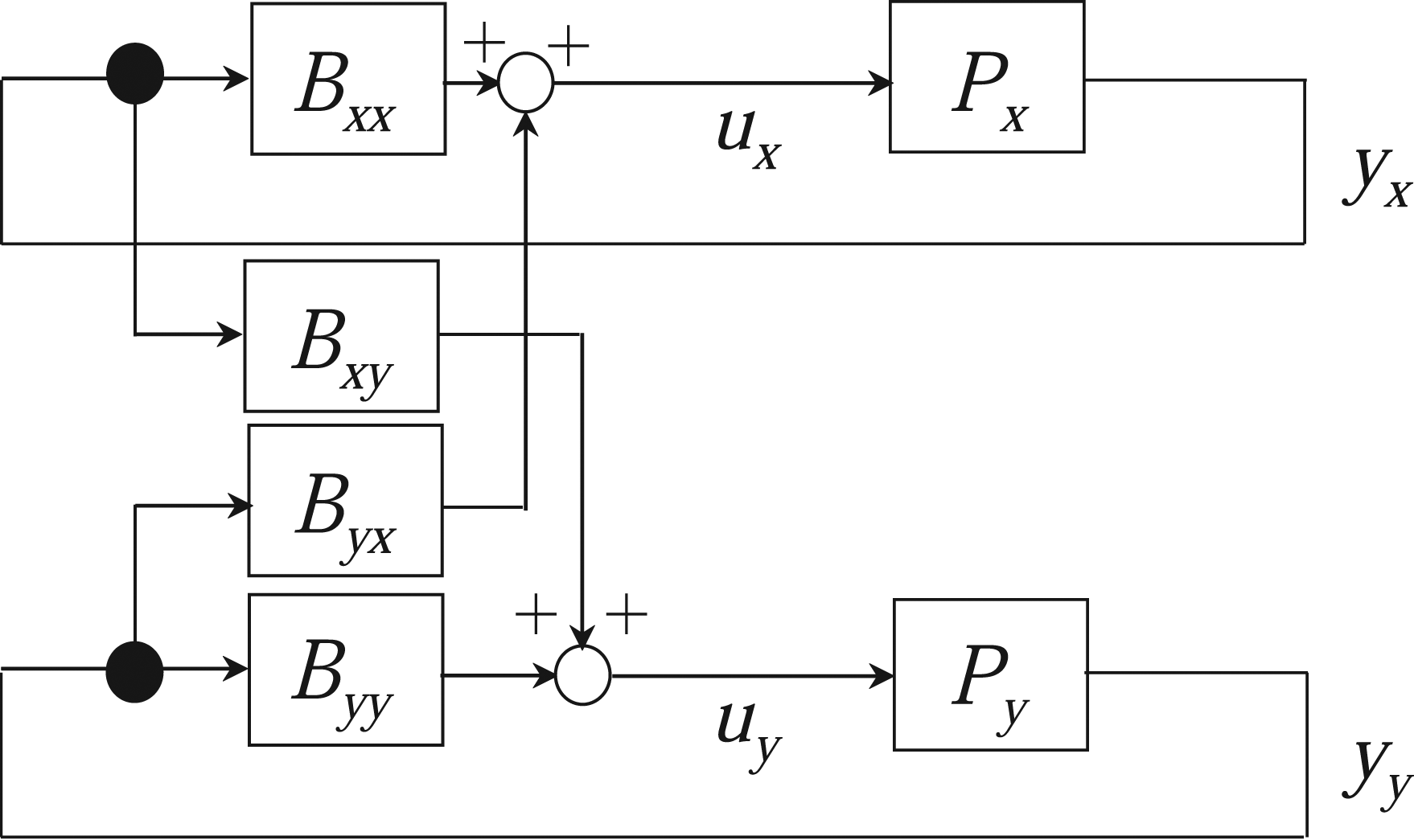
Second, we considered the case of operation with steam-whirl-induced vibration. A schematic of the steam turbine used in this study is shown in Figure 6, where ΔP
x
and ΔP
y
are the models of steam-whirl-induced vibration in the x and y directions, respectively. As the vibration were triggered by the eccentricity of the rotor shaft, the displacement of the shaft was considered as the input for ΔP
x
and ΔP
y
[Hisa et al., 1985, Pennacchi and Vania, 2011]. The characteristics of ΔP
x
and ΔP
y
varied with the load W. The displacement, including the steam-whirl-induced vibration, is defined as Block diagram of the steam turbine with steam-whirl-induced vibration.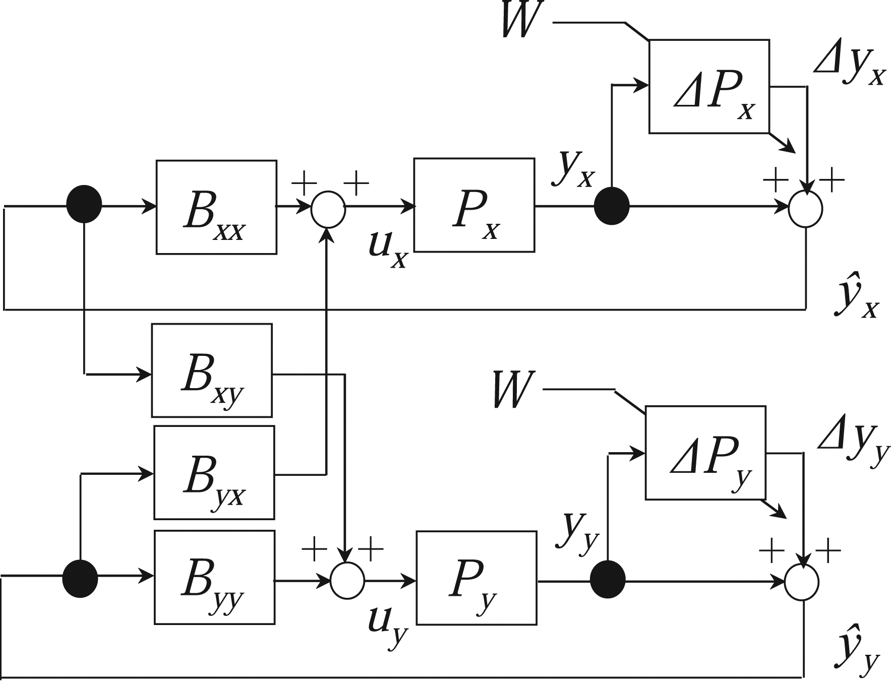
Modeling strategy for steam-whirl-induced vibration
Data processing for the proposed model
The objective of this study was to model ΔP
x
and ΔP
y
as transfer functions to analyze steam-whirl-induced vibration. The displacement signals without vibrations y
x
and y
y
are expressed as


We obtain the following equations by substituting equations (1) and (2) into equations (3) and (4), respectively


Equation (5) can be transformed as follows
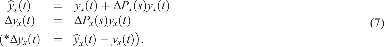
When Δy
x
(t) and

Originally, output (displacement) and input signals of ΔP
x
(s) and ΔP
y
(s) were required to obtain the transfer function. However, the transfer functions ΔP
x
(s) and ΔP
y
(s) were derived only from the displacement signal in the proposed system, as shown in Figure 6. Therefore, actuators that generate input signals are not required for system identification

Identification of transfer function model
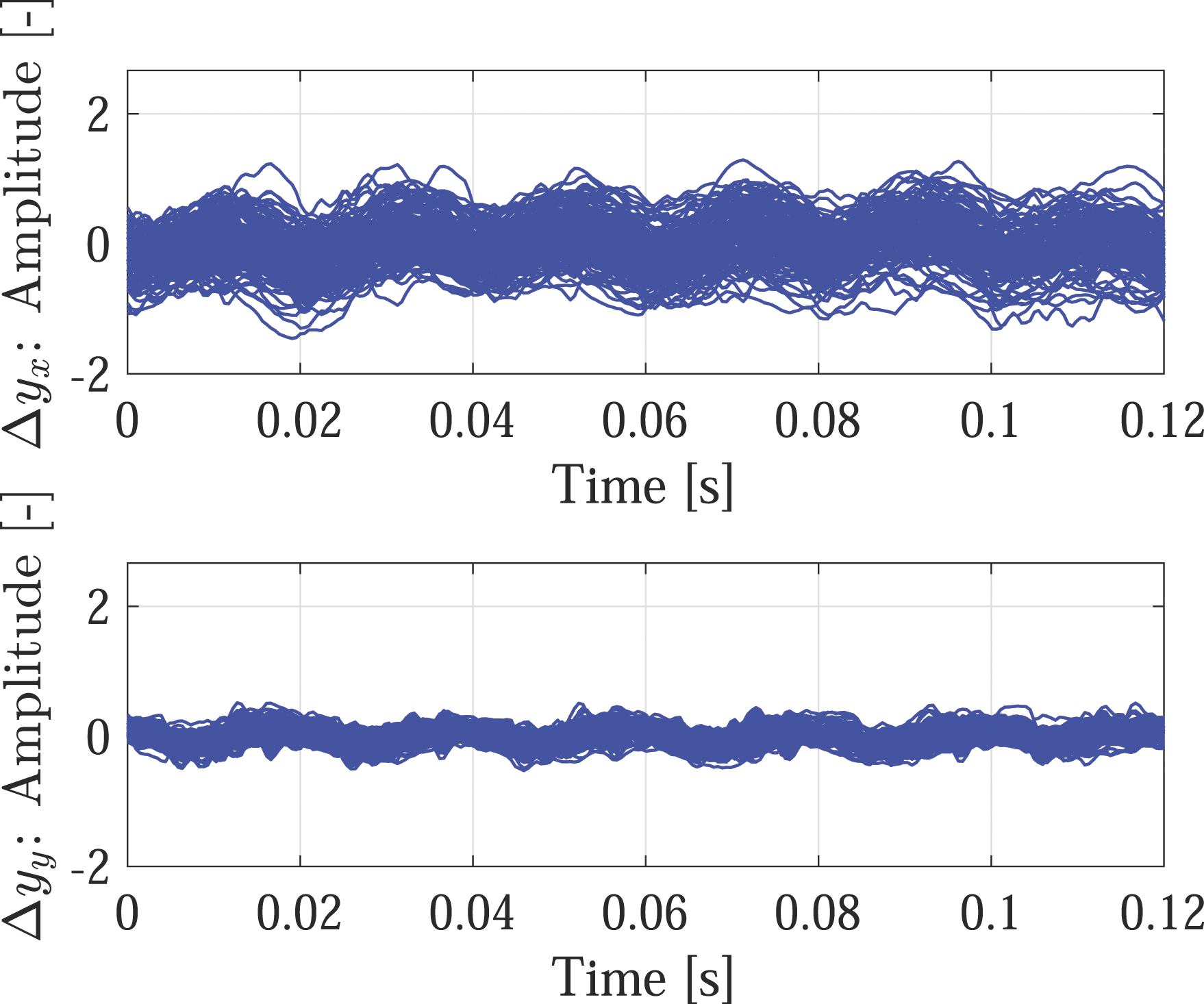
We estimated the transfer function of the steam-whirl-induced vibration from the actual displacement data. Steam-whirl-induced vibration did not occur immediately after the activation of the steam turbine. The displacement signals measured at this time are denoted by y
x
and y
y
. As shown in Figure 4, steam-whirl-induced vibration is observed at approximately 18 Hz by increasing W. In this section, we focus on the displacement signals Time response of displacement signal of the rotating shaft Time response of displacement signal Δyx(t)andΔyy(t) are calculated from data set (2048 point × 120 sets), and all results are overplotted in this figure.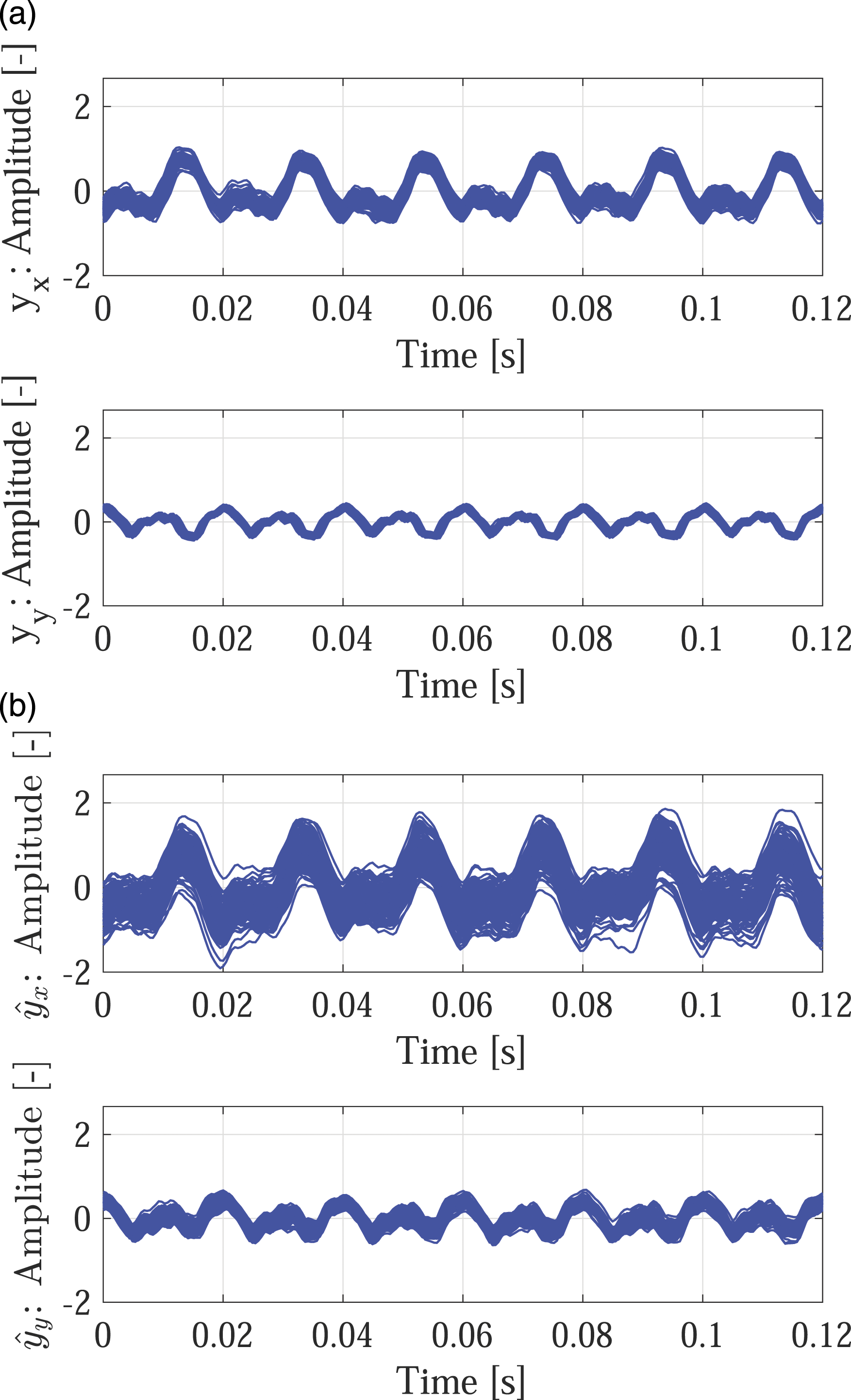
The frequency responses of Frequency responses of 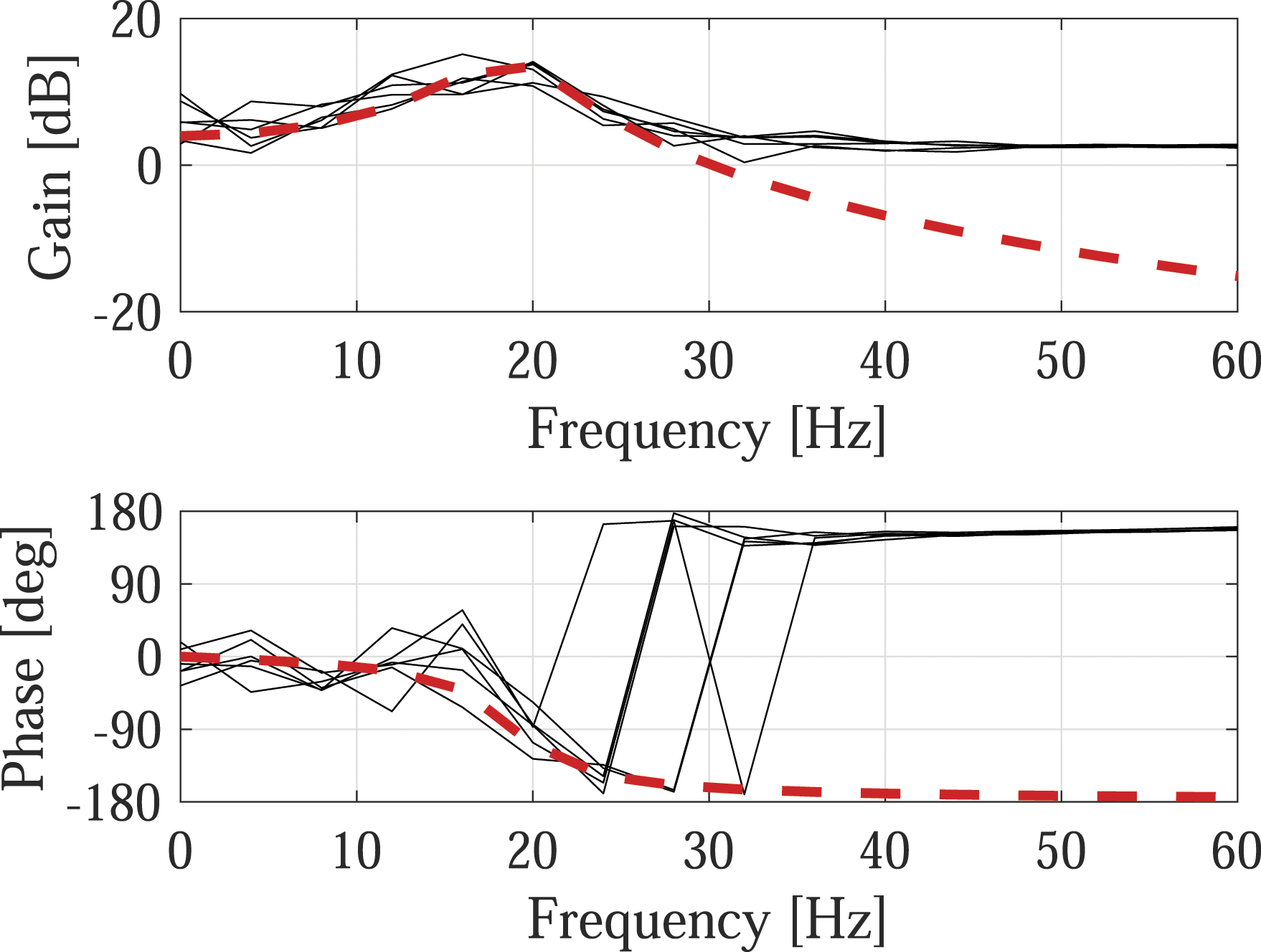

The frequency response of the transfer function is indicated by a dashed line in Figure 9. The frequency response strongly agreed with the experimental results. Additionally, Δy
x
(t) was back-calculated using the measured signal y
x
as the input for ΔP
x
(s). Figure 10 compares the results obtained for y
x
and Δy
x
(t). The time responses of Δy
x
(t) strongly agreed with those of y
x
. Time response of Δy
x
(t) estimated by the transfer function model. Δy
x
(t) is calculated from ΔPx(s), and the original data is calculated from averaging the all measurement data (2048 point × 120 sets).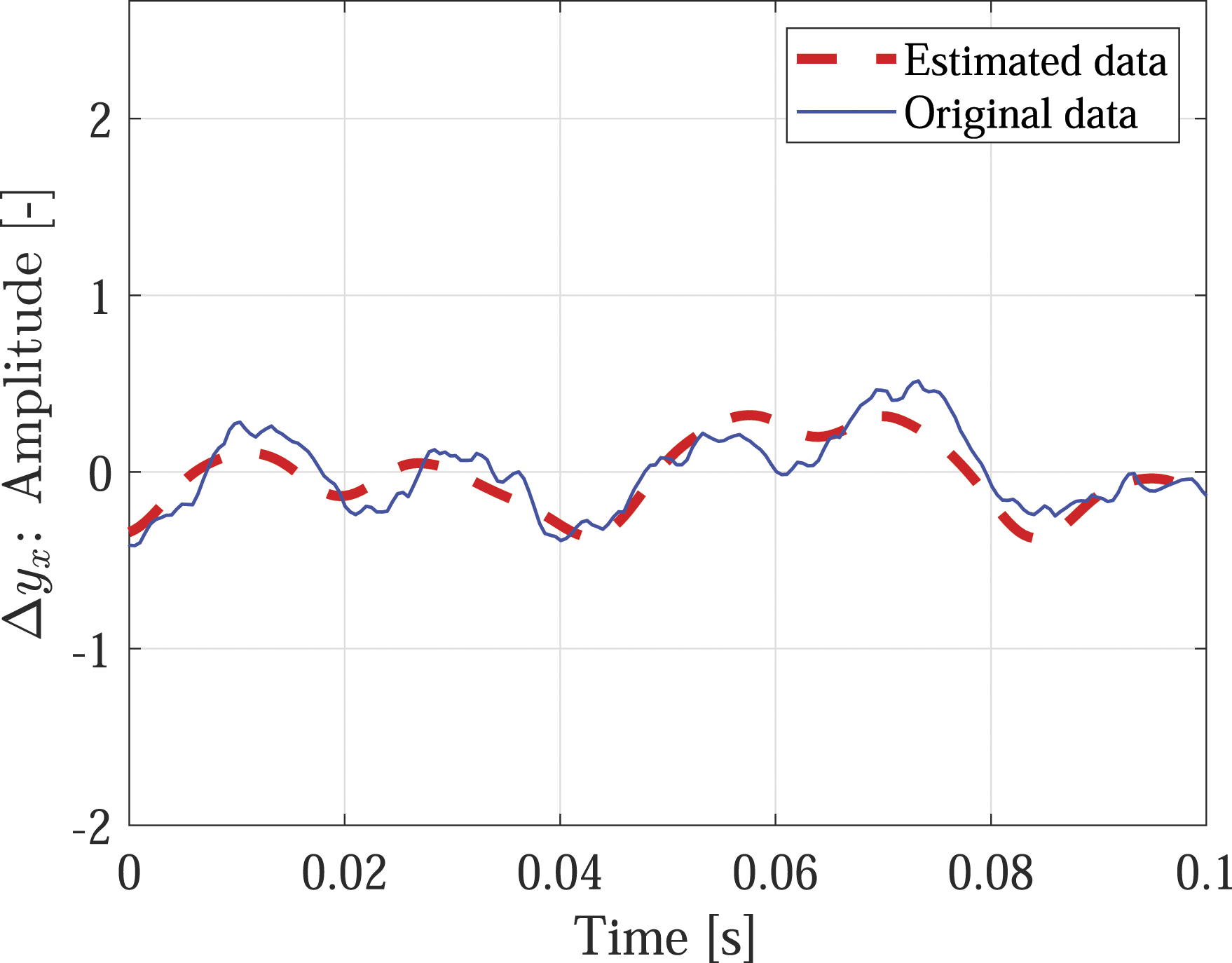
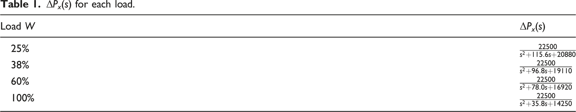
ΔP
x
(s) was determined from the displacement data measured at W = 25%, 38%, and 60%. The frequency responses of Frequency responses of ΔP
x
(s) for each load.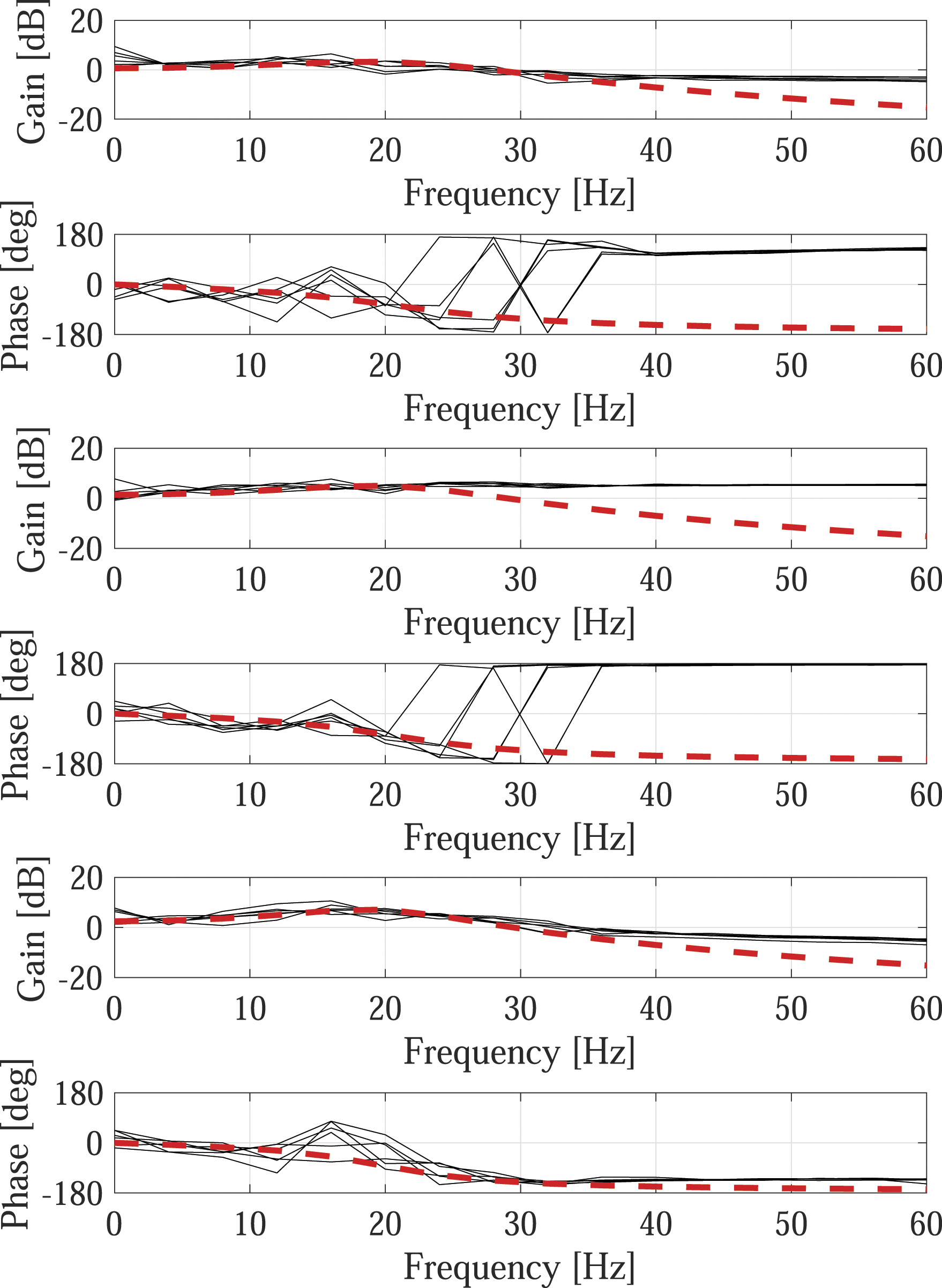
Proposed modeling method and stability analysis for steam-whirl-induced vibration
Stability analysis based on the determined model
The transfer function was estimated from the measured data using a black-box modeling method. However, the parameters of the transfer function were transformed into residue, damping, and stiffness in the modal coordinates. Therefore, the characteristics of the transfer function were evaluated with respect to the mechanical parameters, which were calculated using gray-box modeling. Based on this knowledge, we propose a method for estimating the stable margin of steam-whirl-induced vibration. When the system is considered a lumped mass system, the transfer function is described based on the equation of motion as follows

At W = 100%, the values of
Figure 12 shows the values of Relationship between the load and the identified parameters, 


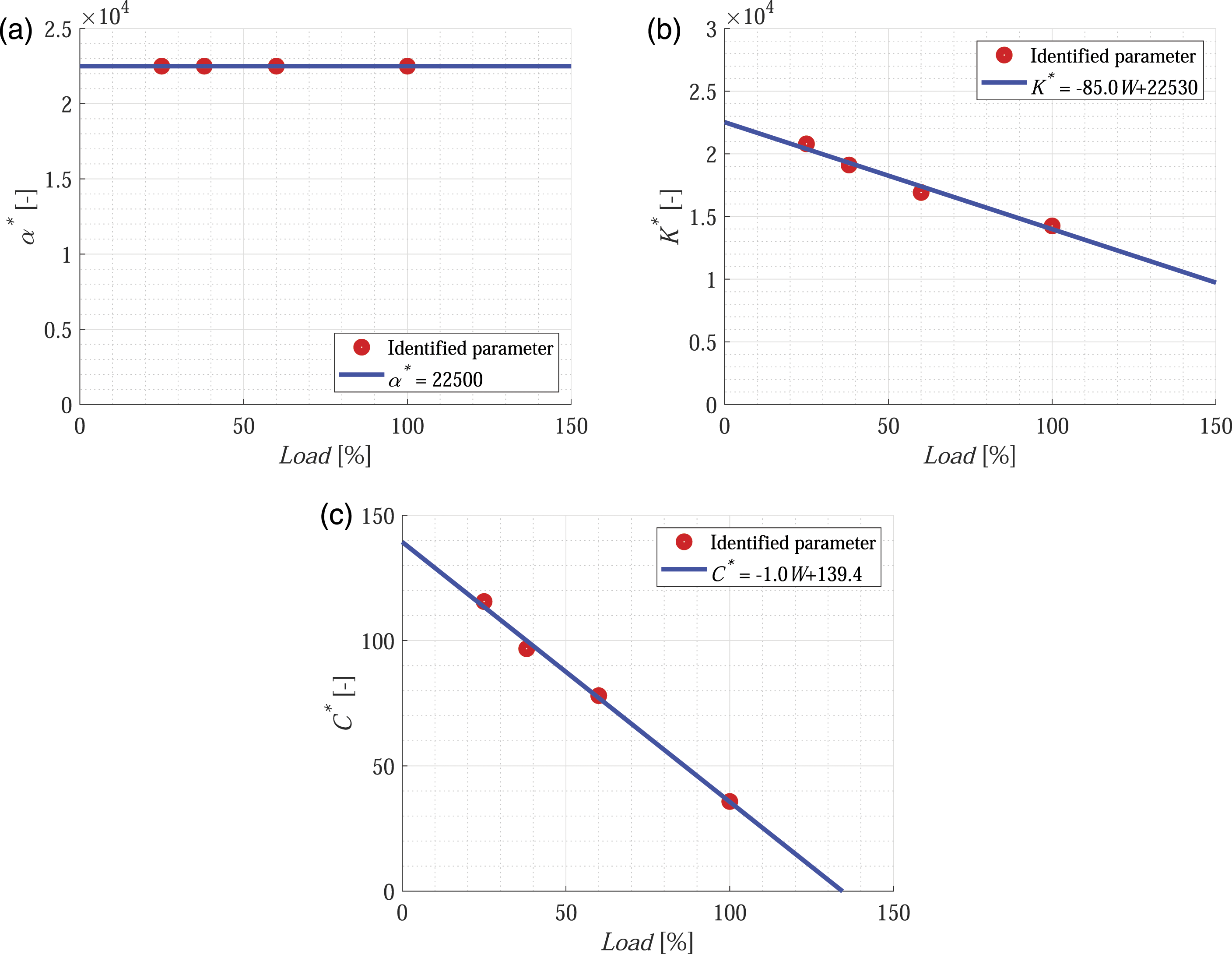
The following observations were made from this result: • α*(W) did not depend on W. • •
Although the residue (mode gain) was constant, the natural frequency and damping depended on the load. In this model, steam-whirl-induced vibration is considered to occur when the damping becomes negative. As shown in Figure 12, self-excited vibration occurs when the load is approximately 1.3 times the maximum load.
Validation of the proposed method
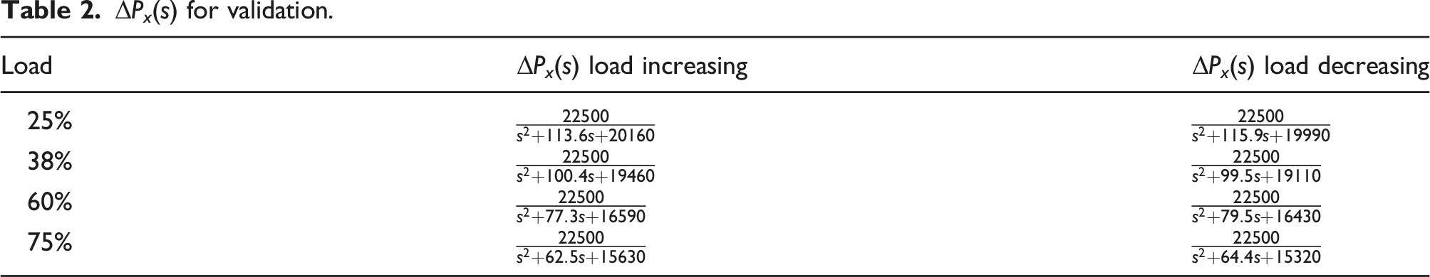
To validate the proposed method, the displacement data of the steam turbine were measured on different days. The operating conditions (rotational speed and load on the steam turbine) are illustrated in Figure 13. When the rotational speed reached 3000 rpm, the displacement data were measured for each loading condition (25%, 38%, 60%, and 75%). Additionally, the displacement data were measured for two loading patterns: gradually increasing and decreasing the load. The frequency responses of Experimental condition of the turbine for validation check. The rotating speed was changed from 0 to 3000 rpm, and the percentage of load was changed from 0% to 75% as shown in this figure.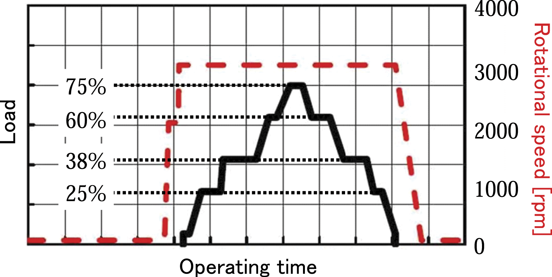
ΔP x (s) for validation.
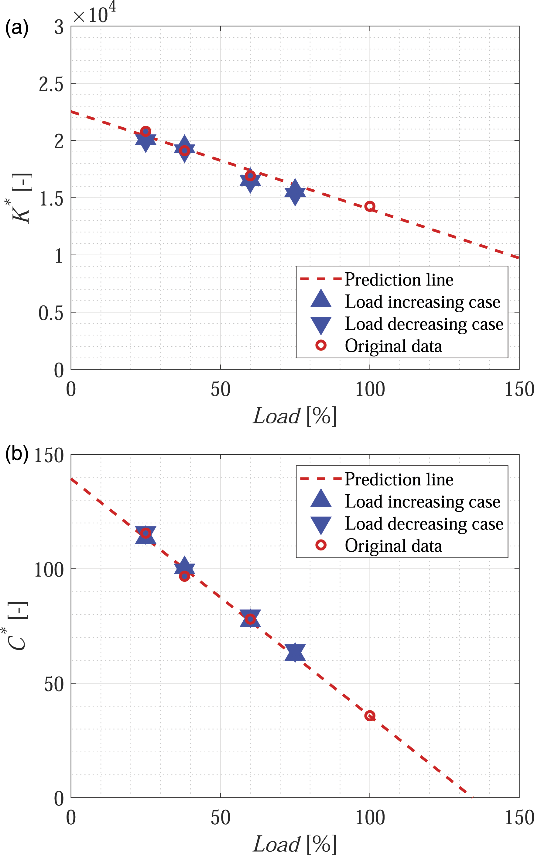
Relationship between the load and the identified parameters with the validation data,
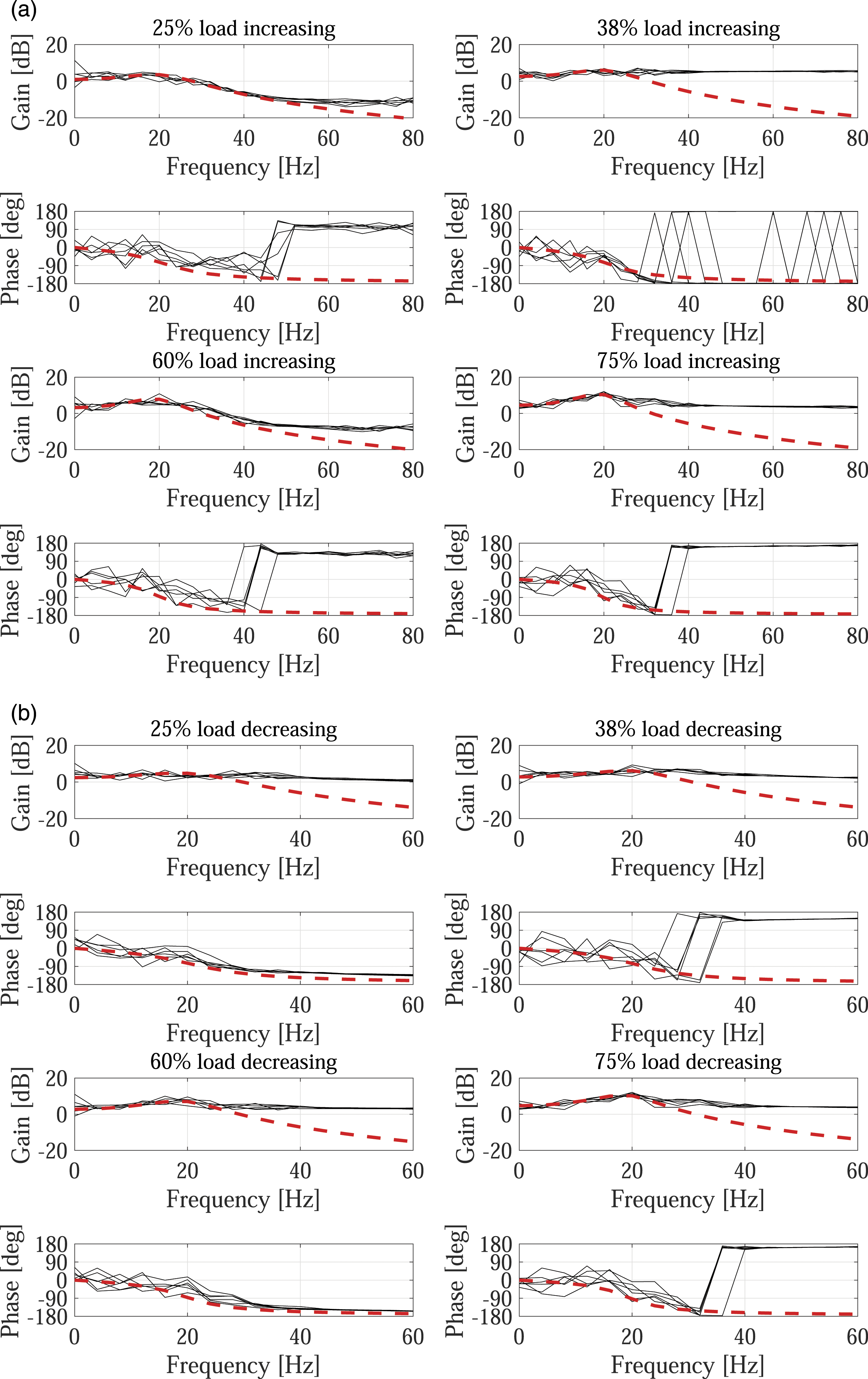
Frequency responses of
Conclusion
We proposed a system identification method to analyze steam-whirl-induced vibration. The following conclusions were drawn: • The steam-whirl-induced vibration can be identified using the direct closed-loop identification system. The difference in displacement signals between the cases with and without steam-whirl-induced vibration is used in this modeling method. • The characteristics of the steam-whirl-induced vibration can be modeled as a second-order transfer function. The frequency and time response of the vibration are in good agreement with the experimental data. • The fluctuation of each coefficient with respect to the load was estimated by calculating the stiffness and damping in the modal coordinates from the transfer function. • We confirmed the validity of the model by applying the proposed method to the operation data for a steam turbine from different days. The model parameters were almost the same. • The proposed method requires displacement data only. The displacement sensor is used for most rotating machineries, and it is easy to incorporate in cases where it has not been adopted. Therefore, the proposed method can be applied to rotating machineries.
The following scope for future research is drawn based on the conclusions of this study: • The instability condition due to the steam-whirl-induced vibration can be predicted using the damping parameter in the proposed model. When the damping parameter becomes negative, the rotating machinery becomes unstable. A feasibility study for the instability prediction will be conducted on a test bench. • The effectiveness of the proposed method has been verified for a steam turbine. To check the generality of the model, it will be used to model the vibration of other steam turbines. Moreover, we will attempt to identify other types of rotating machineries.
Footnotes
Declaration of conflicting interests
The author(s) declared no potential conflicts of interest with respect to the research, authorship, and/or publication of this article.
Funding
The author(s) received no financial support for the research, authorship, and/or publication of this article.