
Abstract
Pushed by social demands, China has continuously developed its low-medium speed maglev transportation systems in recent decades. However, with the increase of the running mileage of the train, high frequency vibration of suspension frame gradually appears. In this paper, a method to analyze the high frequency vibration of suspension frame by detecting the current of traction motor is proposed. Field measurements of suspension frame vibration and traction motor current of low-medium maglev train were conducted on a maglev line that has been commercially put into operation. The test results show that the speed of the measured maglev train was closely correlated with vibration accelerations of the suspension frame in three directions, but as the speed increased, the influence it imposed on the suspension frame vibration waned. The dominant frequency of traction motor resultant current was consistent with the dominant frequency of the suspension frame vibration acceleration. The switching frequency of traction inverter was the main cause of high frequency vibration of suspension frame.
Keywords
Introduction
Maglev suspension train, with the non-contact suspension, guidance, and propulsion technology, has the advantages of low vibration and noise, stable operation, small turning radius and strong climbing ability, which has widely attracted the attention and continuous research of many countries. Unlike the wheel rail system used in high-speed EMUs, the maglev system boasts lower derailment risk, lower noise, less energy consumption and superior environments and services. As the prototype of maglev transport, low-medium speed maglev train is designed for short and medium journeys in cities and most likely to be developed into future urban transit.1,2
At present, the Hilly Line in Japan, Incheon Airport Line in South Korea, Changsha maglev Airport Line in China and Beijing maglev Line S1 have realized commercial operation.3,4 According to the suspension principle, maglev trains can be divided into high temperature superconducting suspension, electro-dynamic suspension (EDS), electromagnetic suspension (EMS) and electromagnetic permanent magnet hybrid suspension. The electromagnetic suspensions are widely used in China, which are pulled by short stator linear induction motor and generally run on viaducts.5,6,7 The traditional wheel rail contact is replaced by the non-contact magnetic interaction between electromagnet and track.
Over the last two decades, a succession of research efforts has been achieved on the dynamic performance of train-track systems for maglev trains, which have contributed significantly to the fulfillment of low-medium speed maglev transportation in this regard. In consideration of rail irregularities, Zhao and Zhai 8 built a 10-DOF model of maglev train to study the maglev train responses and dynamic indexes affecting ride comfort underlying the German maglev express train system. Zheng et al. 9 optimized the maglev train by transforming it into a five-degree-of-freedom model with two-stage suspensions, and simulated the coupled dynamic responses of the system. Hu et al. 10 conveyed the method that using the multi-body dynamics software SIMPACK to establish a three-dimensional maglev train suspension control-bridge coupled dynamic model via China’s 160 km/h maglev train. Lee et al. 11 established a simplified vertical dynamic model of low-medium speed maglev train bridge coupling, and dissected the influence of bridge structural form, material and stiffness on coupled vibration. Han et al. 12 assumed the possible effects that a wide range of design parameters of the guideway might impose on the vehicle dynamic performance, established a dynamic model-an actual vehicle and guideway resemblance, and proposed a limiting value of deflection ratio of the slender guideway to guarantee levitation control.
The researches above are to analyze the dynamic performance of maglev train from the mechanical principle or simulation data, ignoring the harsh environmental conditions suffered by the maglev train when running on the actual line. Therefore, some researchers analyzed the dynamic performance of maglev train from the field test results by testing the operation state of maglev train on the line. Li et al. 13 set up a low-medium speed train with a central air spring suspension frame, studied the dynamic features of the vehicle-rail-bridge coupling system, and conducted field tests on the coupling system in the speed range of 60 km/h to study its natural vibration characteristics. Underlying field measurement and model real-time update method, Zhang and Huang 14 presumed an interaction model of maglev vehicle/guideway, and dissected what impacts distributed magnetic forces and irregularity might impose on the interaction system. Li et al. 15 conducted field tests on low-medium speed maglev trains in Changsha, a city of China, counted the bridge vibration data on two types of prestressed double track concrete bridge tracks, and analyzed the basic dynamic characteristics of the two bridges and compared with those of bridges in multifarious typical maglev lines. In accordance with the operation conditions of Shanghai maglev train, Li et al. 16 selected seven test sections of the line, measured the acceleration response of pier and nearby ground in three directions, and dissected the data in frequency domain and time domain. Underlying laser displacement sensor combination for the high-speed maglev train speed measurement and positioning system, He et al. 17 proposed a data-driven relative position detection scheme, used the detection scheme to collect the vertical displacement signal and established the relative position detection model of one coggle cycle by designing a neural network to sense the periodic change of vertical displacement signal. Guan et al. 18 carried out experimental measurement and quasi steady state to simulate the acoustic damping performance of double-layer and single-layer perforated plates, the measurement can be simulated to carry out the acoustic study of the maglev train body. Zhang et al. 19 analyzed the manifestation of the traveling leakage magnetic field in the presence or absence of the inter-chip short-circuit fault and the interferences in the magnetic field measurement environment, to resolve the short-circuit fault between the long stator slices of the high-speed maglev train. Lim et al. 20 analyzed and experimentally evaluated the power consumption and effective normal force of maglev train, adopted vector control algorithm and various air gaps to improve propulsion efficiency and reduce system energy consumption, the air gap and normal force of linear induction motor were calculated and compared with the traditional finite element method.
To study the dynamic response features of the suspension frame vibration caused by low-medium maglev, a method to study the high frequency vibration of suspension frame by detecting the current of traction motor is proposed in this paper. Field measurements of suspension frame vibration and traction motor current of low-medium maglev train were conducted on a maglev line that has been commercially put into operation. Three test sections of the maglev Line were chosen in accordance with actual operating conditions. Vibration acceleration of suspension frame in three directions and three-phase current of traction motor were measured. Influence of maglev train speed on suspension frame vibration and traction motor current were assessed according to their peak values of test data at a given test section. Finally, the causes of suspension frame high frequency vibration are analyzed from the frequency domain of vibration acceleration and traction motor current data.
Theoretical background
Under the operation of suspension controller, the low-medium speed maglev train can be stably suspended with track excitation and external excitation, so as to keep the vehicle fluctuating within a reasonable suspension air gap. Ignoring the factors such as magnetic leakage and magnetoresistance, the mechanical and electrical equations of single magnet suspension can be expressed as
21


From equations (1)–(3), it can be seen that there is a mathematical relationship between the vibration of suspension frame and traction motor current. In order to find the high frequency vibration causes of low-medium speed maglev train suspension frame, it is necessary to measure the vibration acceleration of suspension frame and the current of traction motor.
Experimental measurements
In this experiment, carriage two of the low-medium speed maglev train was selected as the main test object. The location of vibration acceleration measurement points was selected on the suspension frame of the ninth traction motor, and current sensors were arranged on the current input of the ninth traction motor. Figure 1 shows the positions of the vibration acceleration sensors and the current sensors on the suspension frame of carriage 2. Layout of the measuring points.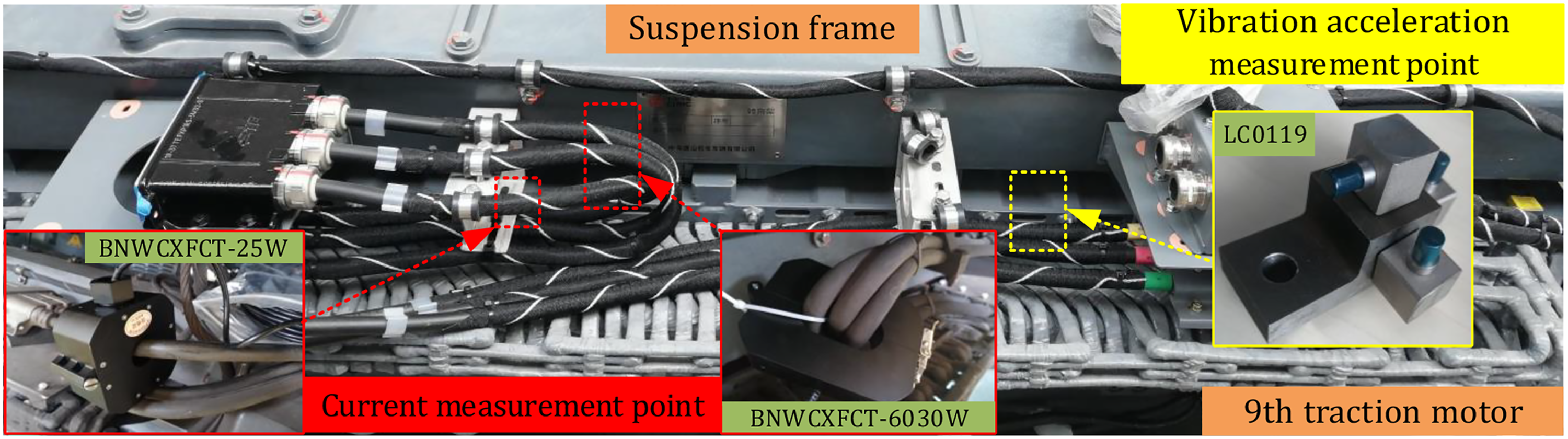
Vibration acceleration and current caused by low-medium speed operation of trains in the test line are highly dense and complex. Sensors with a high sensitivity and the high threshold are needed to measure the vibration acceleration and input current accurately. The current sensors used on the traction motor are BNWCXFCT-25W and BNWCXFCT-6030W current sensors manufactured by Tianrui electronic company. The range of BNWCXFCT-25W current sensor is 600A, and the accuracy is within 0.1%. The range of the other current sensor is 10A and the accuracy is within 0.05%. The vibration acceleration sensors used on the suspension frame are LC0119 piezoelectric acceleration sensors (sensitivity of 500 mV/g and measuring range of 10 g) produced by Lance company. The sampling frequency of all sensors used in the actual test was 50,000 Hz, being sufficient to guarantee the accuracy of the features of the vibration acceleration and current transients. 22
To ensure the real-time accuracy of the collected data and the large-capacity storage of the data, four integrated measurement control (IMC) systems to jointly collect suspension frame vibration acceleration and traction motor current signals, which effectively overcomes the problem of asynchronous vibration acceleration and current in this test. The field installation layout of IMC data acquisition systems and sensors is shown in Figure 2. The field installation layout of IMC data acquisition systems and sensors.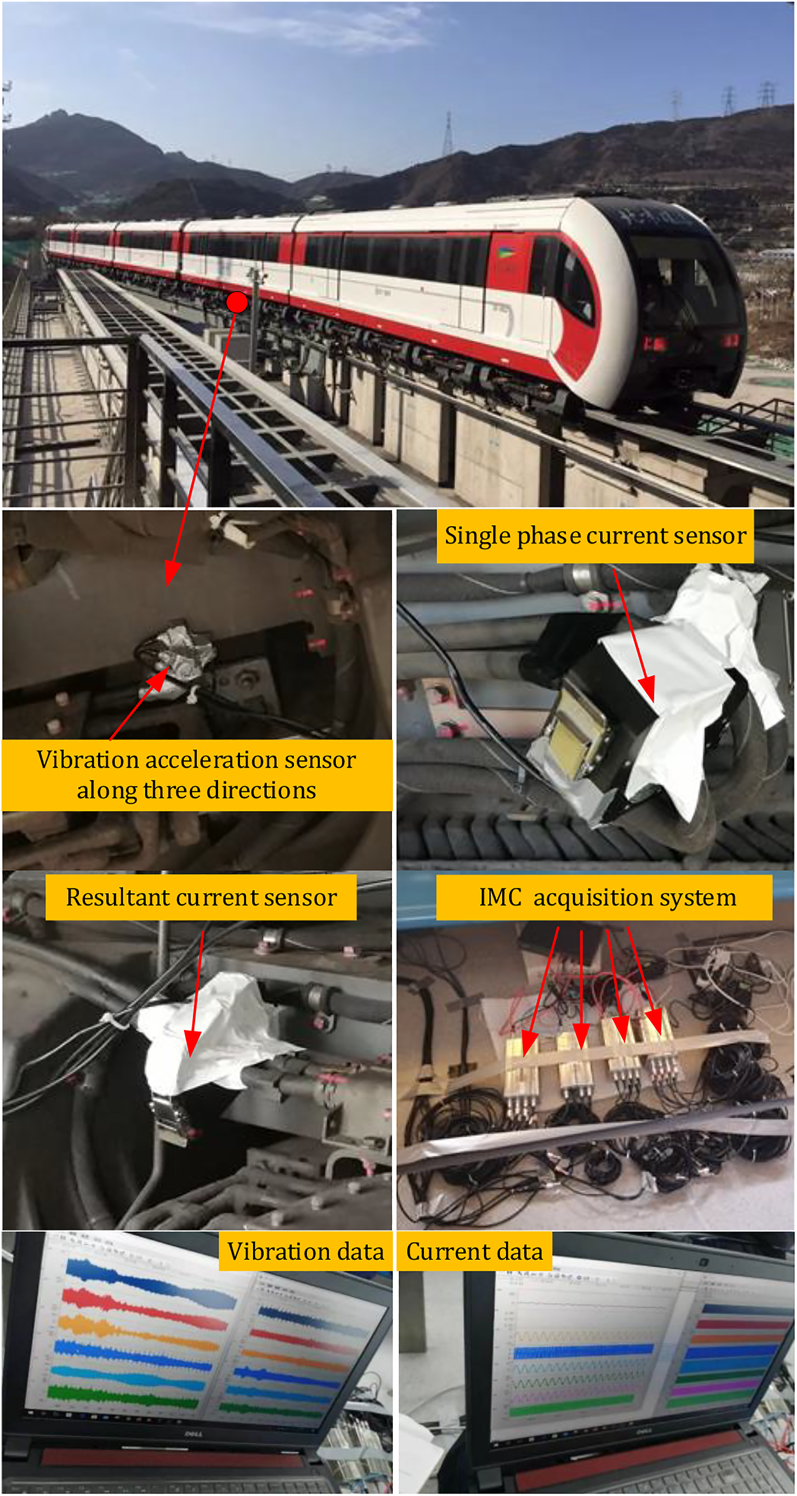
To study the influences of train speed and traction motor current on the suspension frame vibration, a low-medium maglev train was used as the experimental object. Three measurement sections and test speeds were chosen, as shown in Figure 3. Arrangement of test sites and test speeds.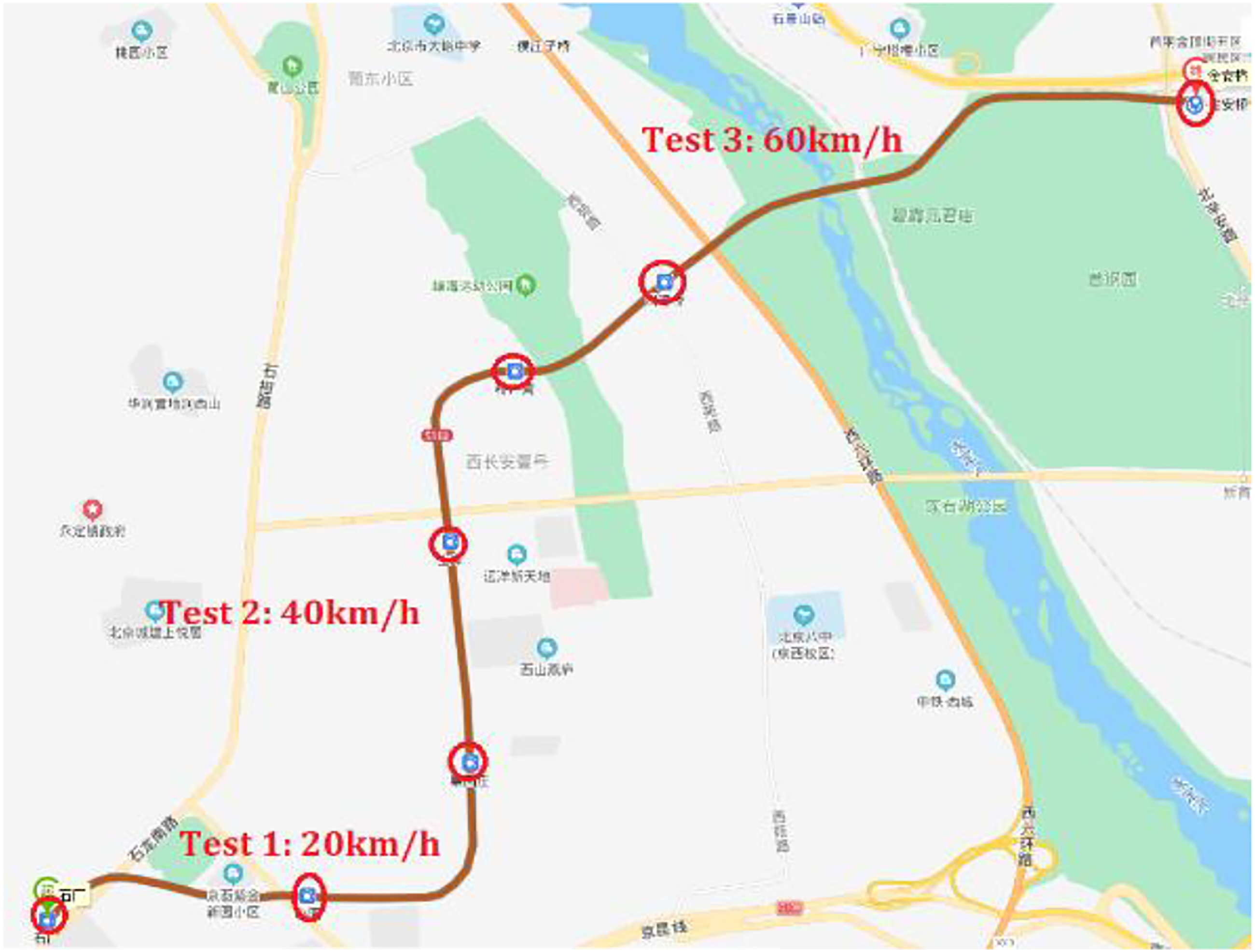
Experimental measure results
In this section, the test results of suspension frame vibration and traction motor current of the low-medium speed maglev operating on the test line with speeds changing from 0 to 20 km/h,0–40 km/h, and 0–60 km/h. After the low-medium speed maglev train accelerated to the specified speed, kept the constant speed for a period of time, and then brake to stop. The influence of maglev train speed and traction motor current on the suspension frame vibration were discussed in terms of their constant speed at a specified test section.
Effect of maglev train speed on suspension frame vibration
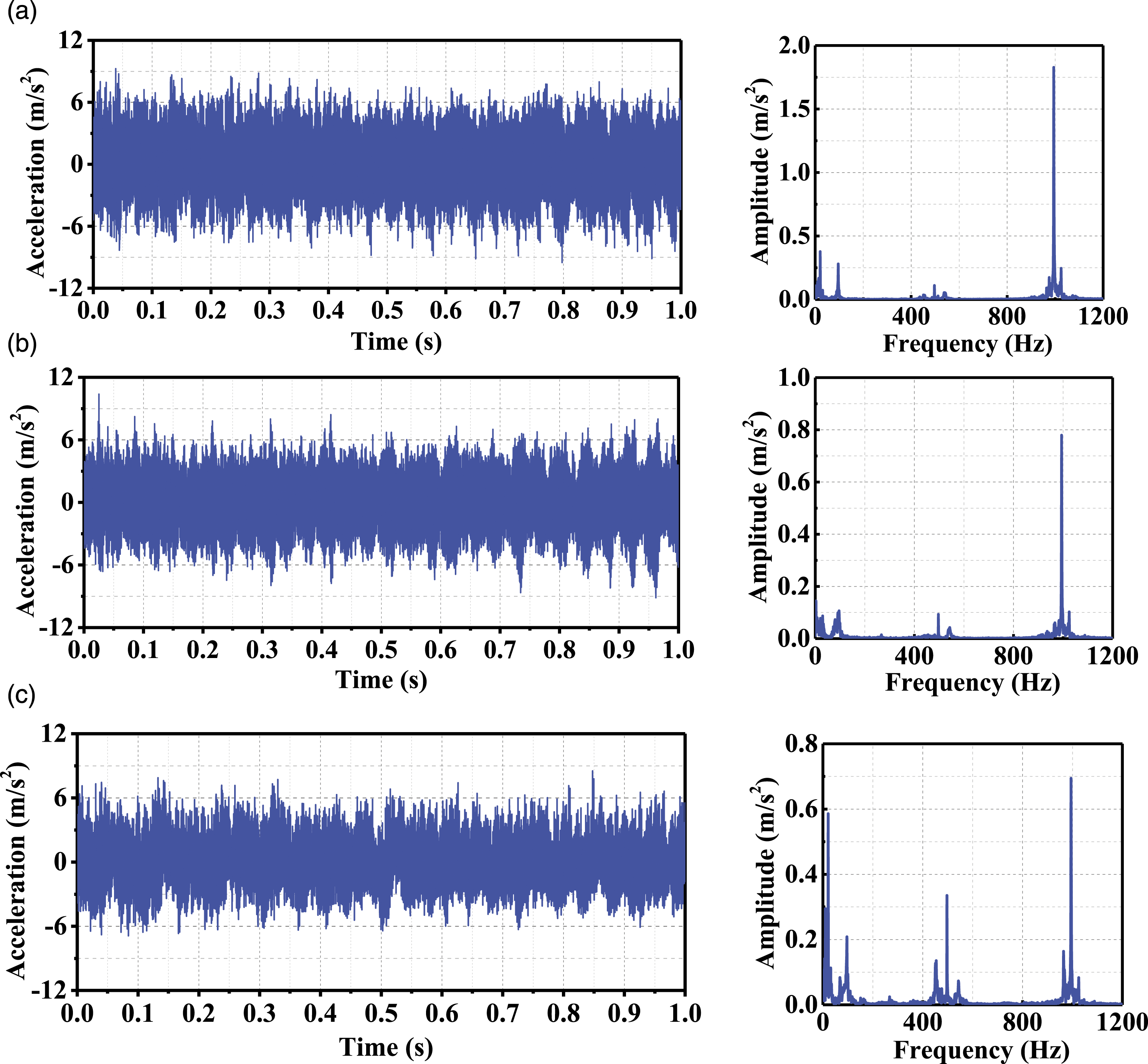
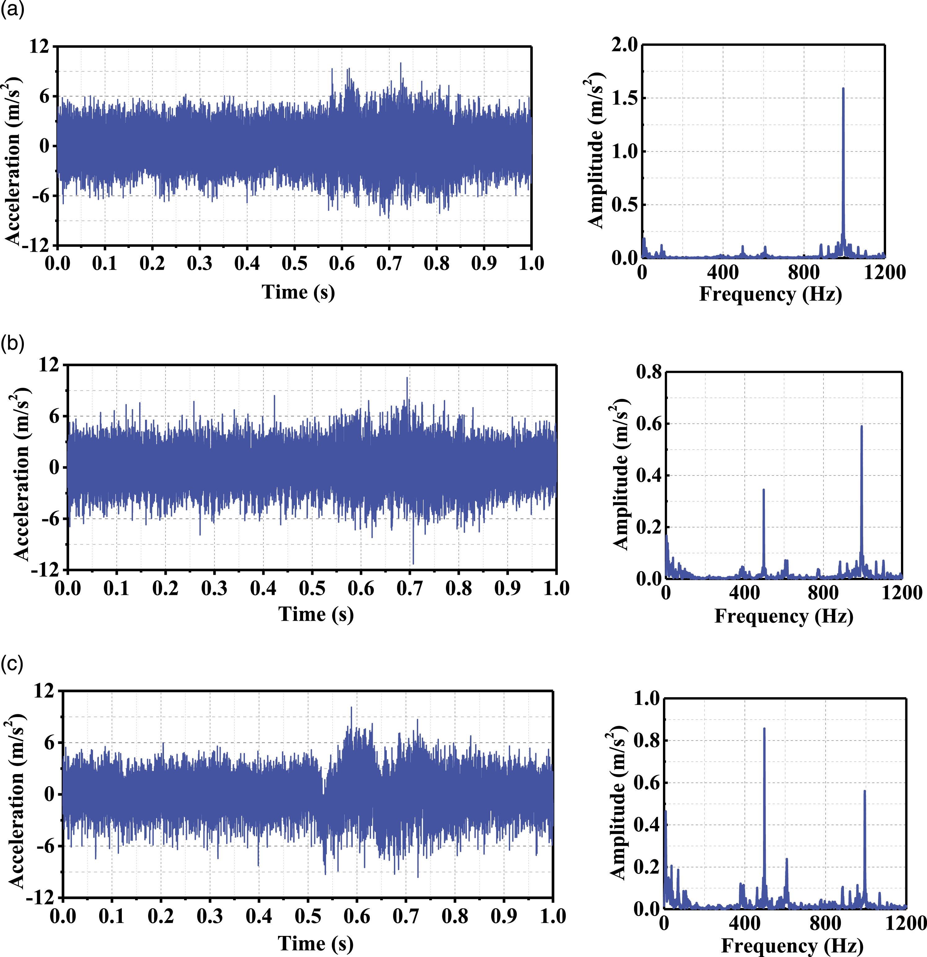
Suspension frame vibration caused by the low-medium speed maglev train at the speeds of 20 km/h, 40 km/h, and 60 km/h were measured in three directions, as shown in Figure 4, Figure 5 and Figure 6, respectively. Time domain and frequency domain of suspension vibration acceleration responses at 20 km/h maglev train speed: (a) longitudinal, (b) lateral, and (c) vertical. Time domain and frequency domain of suspension vibration acceleration responses at 40 km/h maglev train speed: (a) longitudinal, (b) lateral, and (c) vertical. Time domain and frequency domain of suspension vibration acceleration responses at 60 km/h maglev train speed: (a) longitudinal, (b) lateral, and (c) vertical.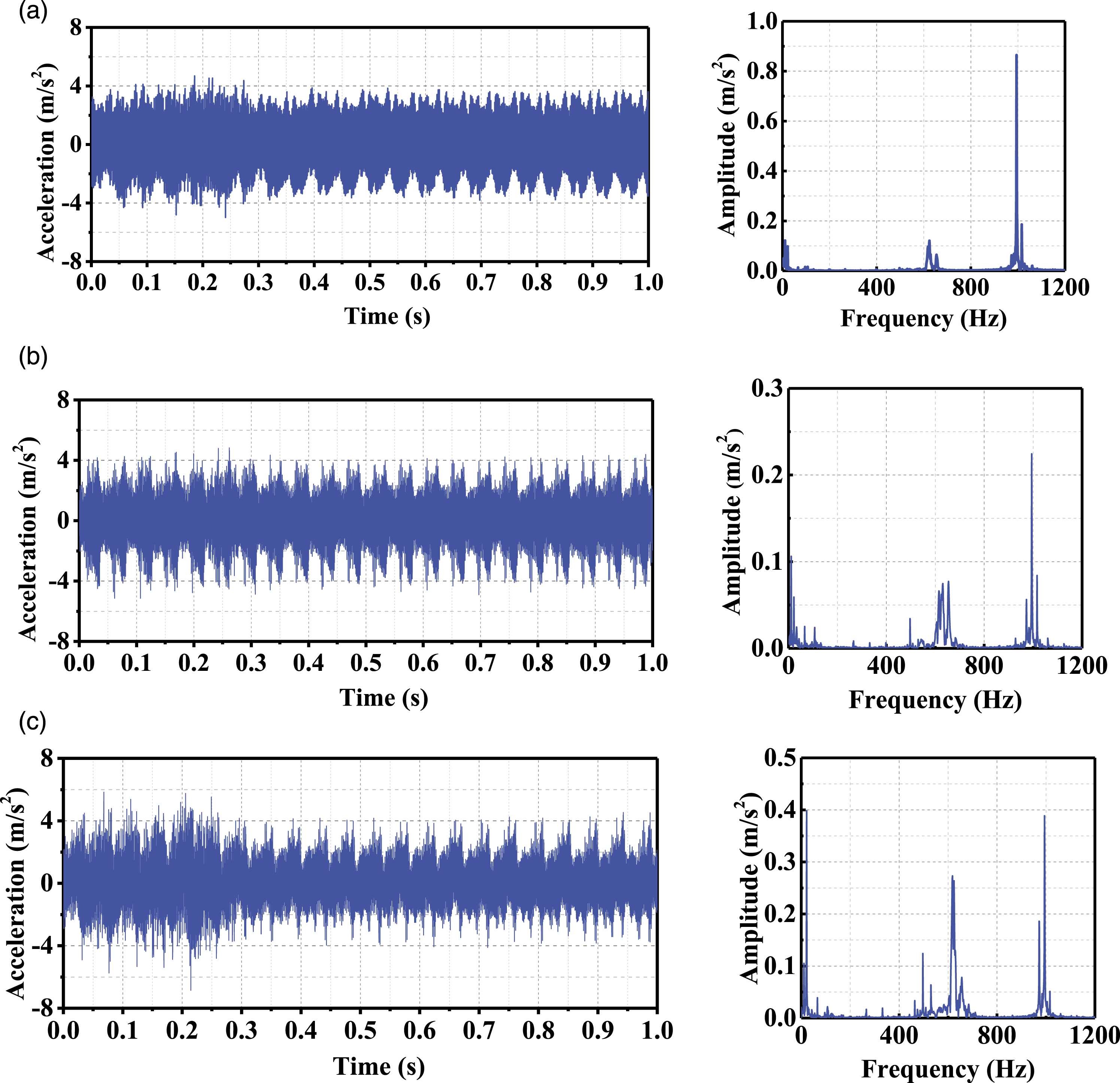
The peak vibration acceleration responses of the suspension frame were picked up from Figure 4, Figure 5 and Figure 6 with the results shown in Figure 7. Peak acceleration responses of the suspension frame under different operating conditions.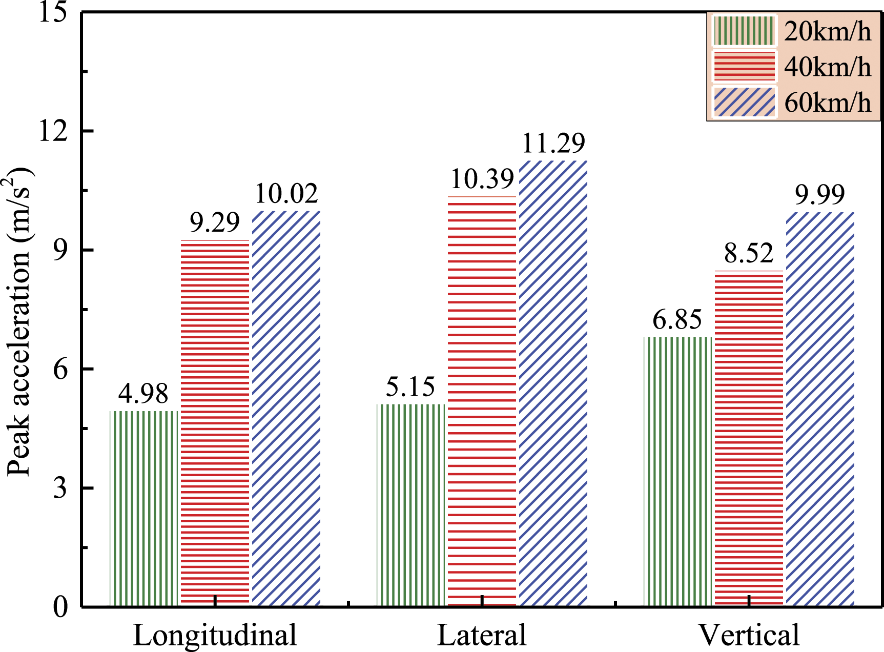
The peak vibration acceleration of the suspension frame in the lateral direction is significantly high, up to 11.29 m/s2, when the speed of low-medium speed maglev train is 60 km/h. When the maglev train speed increases from 20 km/h to 40 km/h, the lateral and vertical suspension frame vibration accelerations are increased by 5.24 m/s2 and 1.67 m/s2, respectively. The lateral and vertical suspension frame vibrations are increased by 0.9 m/s2 and 1.47 m/s2, as the speed of maglev train grows from 40 km/h to 60 km/h. With the increase of maglev train speed, the vibration acceleration in three directions increases, but the increasing amplitude is slower and slower. The test results show that the speed of the measured maglev train is closely correlated with the vibrations of the suspension frame in three directions, but as the speed increases, the influence it imposes on the suspension frame vibration wanes.
In order to study the correlation between suspension frame vibration and maglev train speed, the test data with speed of 70 km/h are added to this paper for discussion. Figure 8 shows the change of peak vibration accelerations along three directions with the speed of maglev train changing from 20 to 70 km/h. Change of peak vibration accelerations along three directions with the speed of maglev train: (a) longitudinal, (b) lateral, and (c) vertical.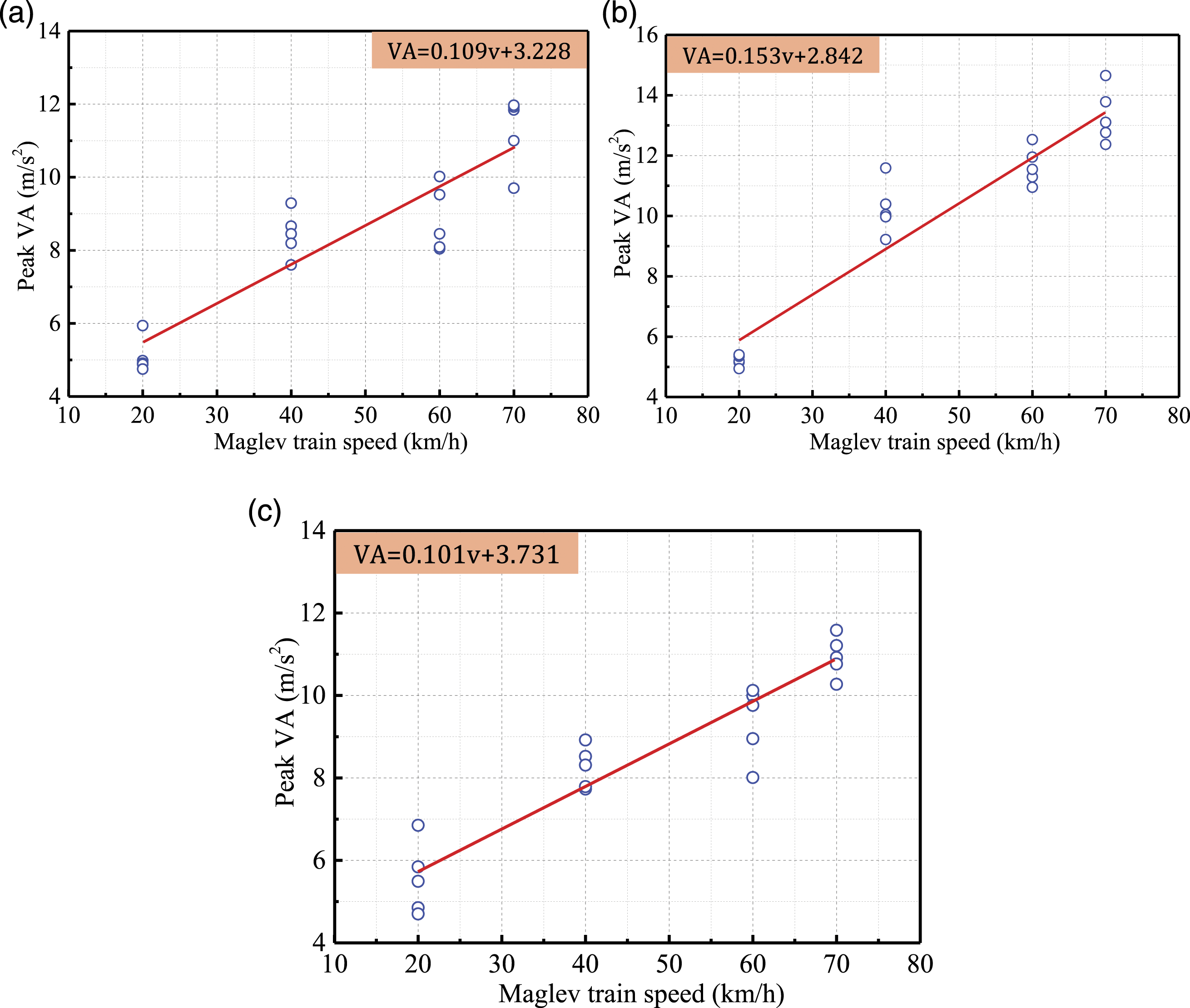
In Figure 8, as the maglev train speed increases, the peak vibration acceleration amplitude in time domain shows different linear upward trends under different speed of maglev train. According to the measured data, the variation tendencies of peak vibration acceleration amplitude along three directions with the speed of maglev train are linearly fitted. These linear fitting formulations show that the peak value of lateral vibration acceleration increases faster, which reveals the strong effect the maglev train speed can impose on the peak vibration accelerations along three directions.
Effect of maglev train speed on traction motor current
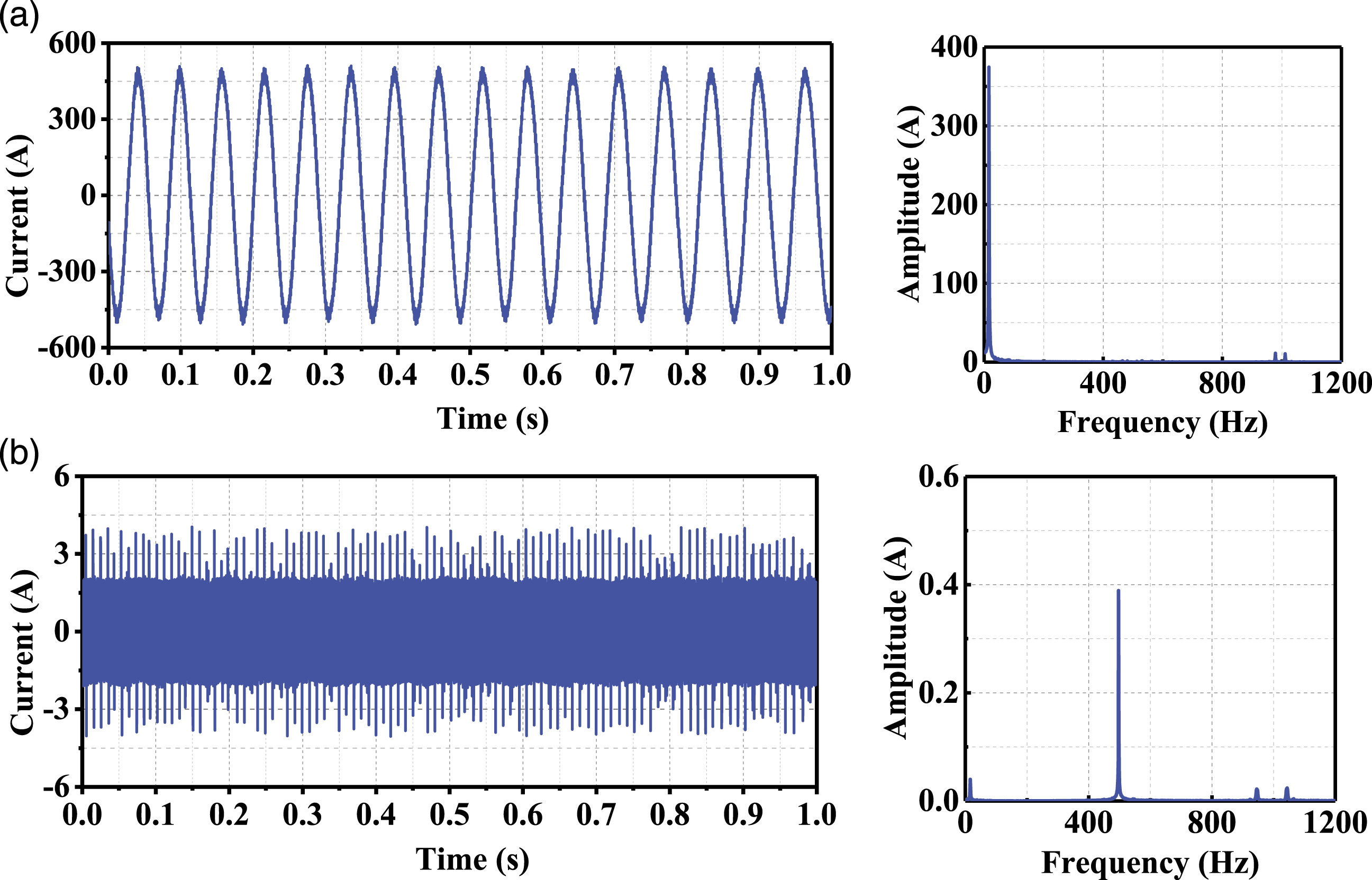
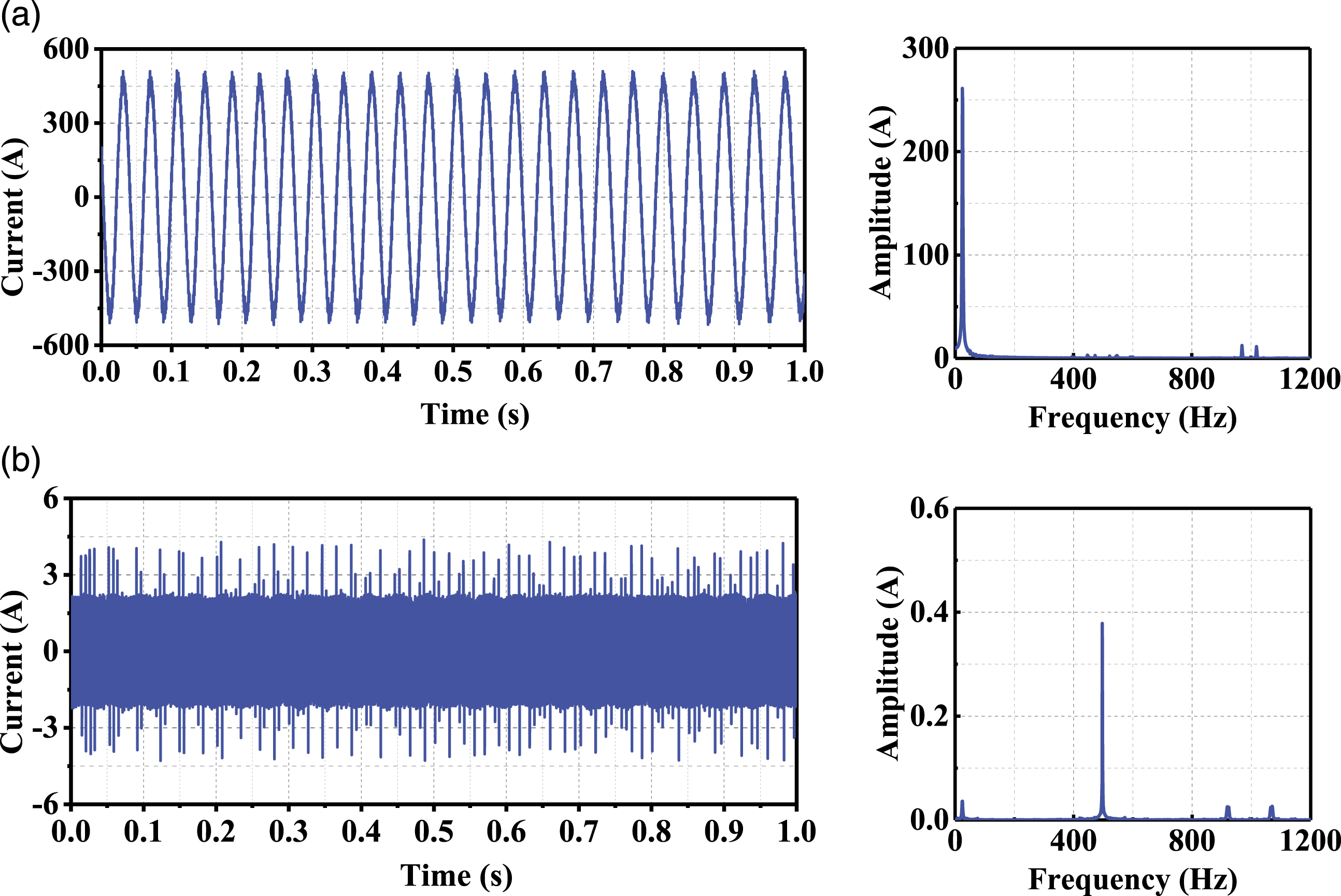
In order to better understand the relationship between suspension frame vibration and traction motor current, it is necessary to study the time domain and frequency domain of traction motor input current at different maglev train speeds. Traction motor input current induced by the low-medium speed maglev train at speeds of 20 km/h, 40 km/h, and 60 km/h were measured, as shown in Figure 9, Figure 10 and Figure 11, respectively. Time domain and frequency domain of current responses of the maglev train speed at 20 km/h: (a) phase A, (b) phase B, (c) phase C, and (d) resultant current. Time domain and frequency domain of current responses of the maglev train speed at 40 km/h: (a) phase A and (b) resultant current. Time domain and frequency domain of current responses of the maglev train speed at 60 km/h: (a) phase A and (b) resultant current.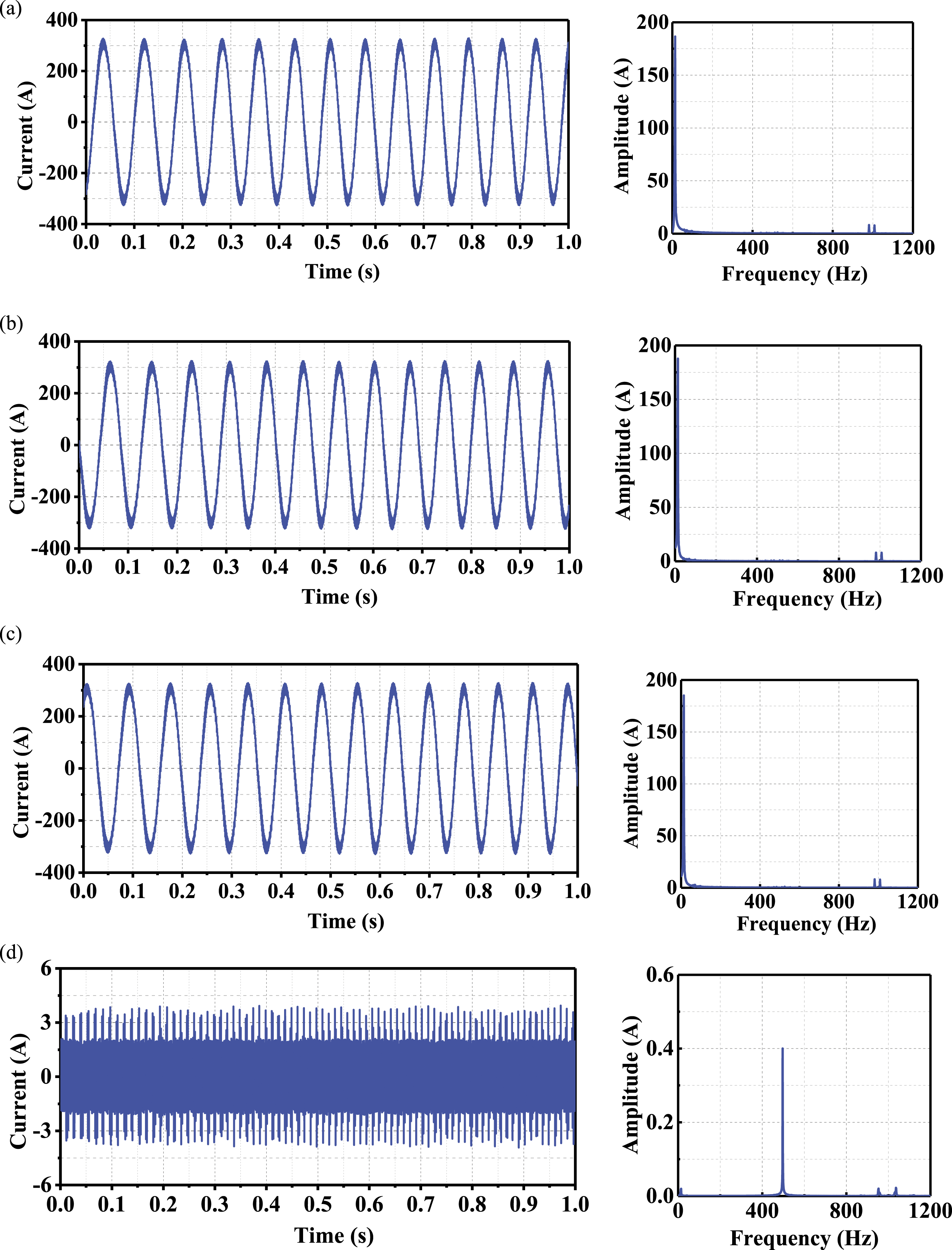
The phase A current responses and dominant frequency of the traction motor were picked up from Figure 9, Figure 10, and Figure 11, and the results are shown in Figure 12. Phase A current responses of the traction motor under different operating conditions: (a) peak current and (b) dominant frequency.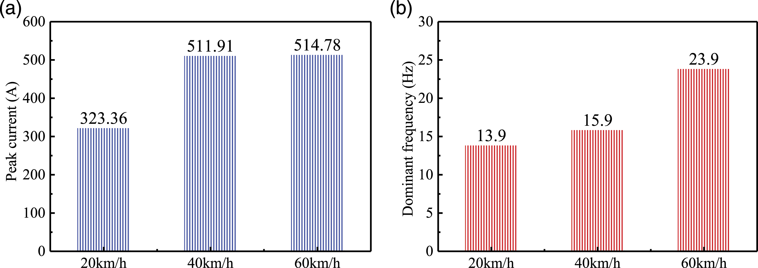
In Figure 12, peak current and dominant frequencies of the traction motor input current in single-phase increase with the growth of maglev train speed. When the maglev train speed increases from 20 km/h to 40 km/h, the peak current increases by 188.55 A, the dominant frequency of input current is increased by 2.0 Hz. However, as the maglev train speed grows from 40 km/h to 60 km/h, the peak current increases by 2.78 A, the dominant frequency of input current is increased by 8.0 Hz. The results reflect the variable frequency speed regulation characteristics of linear induction traction motor, and also reflect the nonlinear relationship between traction motor current and maglev train speed.
In order to further study the nonlinear correlation between traction motor input current and maglev train speed, the test data with speed of 70 km/h are added to the paper for discussion. Figure 13 shows the variation of peak current amplitude varying with maglev train speed in the range of 20–70 km/h. Peak current amplitude varying with the speed of the maglev train.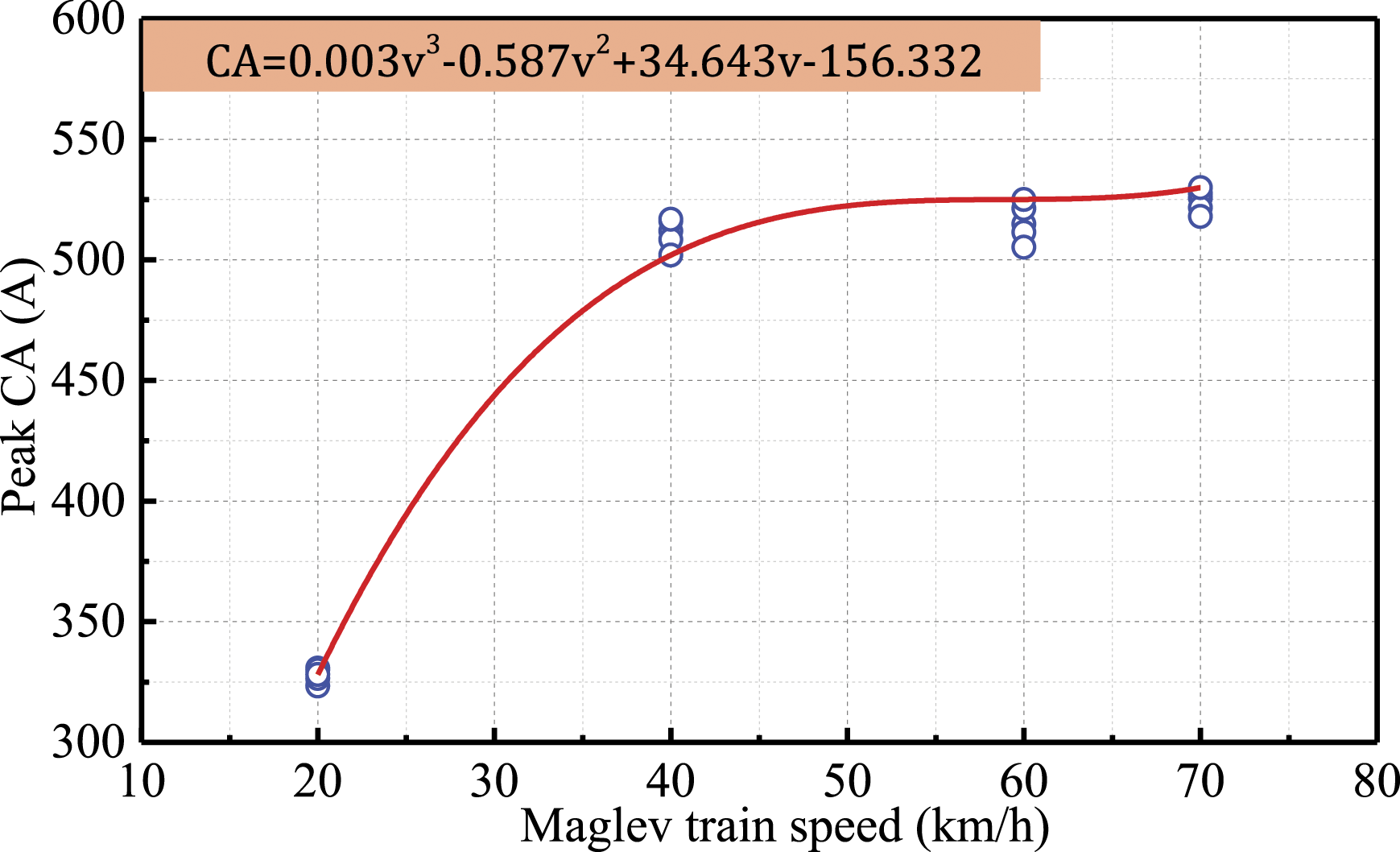
In Figure 13, as the speed of maglev train grows, the peak current amplitude of phase A changes greatly when the maglev train accelerates from 20 km/h to 40 km/h. However, when the maglev train accelerates from 40 km/h to 60 km/h and 60 km/h to 70 km/h, the peak current amplitude changes slowly. The change trends of the peak current amplitude with the speed of maglev train are nonlinearly fitted according to the measured data. From these nonlinear fitting formulations, the results show that during the initial acceleration of maglev train, the traction force demand is large and the current supply increases rapidly. When the speed reaches up to 50 km/h, the traction force required for speed increase gradually decreases and the current supply increases slowly.
Effect of traction motor current on suspension frame vibration
Through the comparison of the suspension frame vibration acceleration frequency spectra shown in Figure 4, Figure 5 and Figure 6, it can be observed that the dominant frequency of longitudinal vibration acceleration is 993.9 Hz at each speed level tested. In addition to the low frequency oscillation excited by structural vibration, the dominant frequencies of lateral and vertical vibration acceleration are concentrated at 496.9 Hz and 993.9 Hz, which is very close to the switching frequency 500 Hz and its double frequency of the traction inverter used in the low-medium speed maglev train.
The high frequency vibration of the suspension frame may also be caused by the bending mode of the surrounding traction motor coil. To gain insight on the deformation, modal analysis of the traction motor coil by using ANSYS software,
24
Figure 14 shows the seven-order and ninth-order natural bending modes of the traction motor coil. Bending mode of traction motor coil: (a) seventh-order and (b) ninth-order.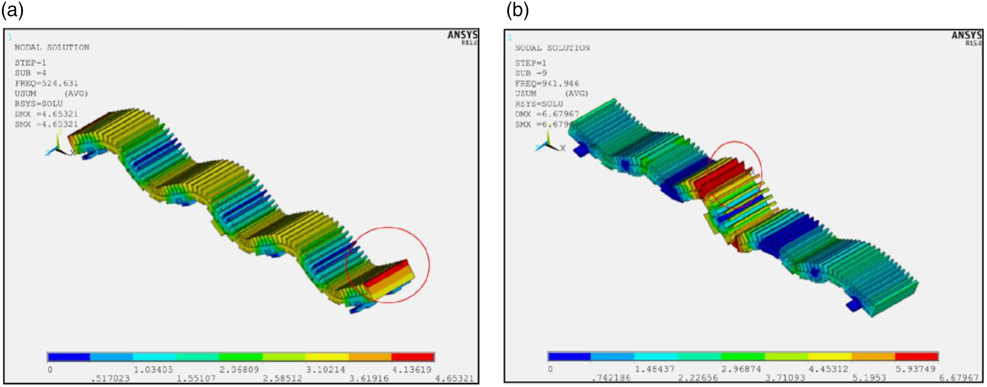
In Figure 14, (a) large difference can be observed between the seventh-order or ninth-order natural bending modes and the main frequency obtained from the acceleration vibration test data of the suspension frame. Therefore, the high frequency vibration of suspension frame does not come from the seventh-order or ninth-order natural bending vibration mode of the coil around the traction motor. It is preliminarily confirmed that the high frequency vibration mainly comes from the switching frequency and its double frequency of the traction inverter.
As can be seen from Figure 10, Figure 11 and Figure 12, it is intuitively found from the spectrum diagram that there is almost no main frequency of 496.9 Hz for single-phase current, but the main frequency of 496.9 Hz always exists in resultant current, and does not change with the speed of maglev train. It is not a coincidence that the dominant frequency of traction motor resultant current is consistent with the dominant frequency of suspension frame vibration acceleration. The switching frequency of traction inverter is the main cause of high frequency vibration of suspension frame.
Conclusions
Field measurements of suspension frame vibration and traction motor current of low-medium maglev train were conducted on a maglev line that has been commercially put into operation. By dissecting the measured data, the influence of maglev train speed on the suspension frame vibration and traction motor current were discussed in terms of peak acceleration at a specified test section. Finally, the causes of high frequency vibration of suspension frame are analyzed from the distribution of vibration acceleration and traction motor current in frequency domain. Some conclusions can be drawn: (1) The speed of the measured maglev train is closely correlated with vibration accelerations of the suspension frame in three directions, but as the speed increases, the influence it imposes on the suspension frame vibration wanes. (2) During the initial acceleration of maglev train, the traction force demand is large and the current supply increases rapidly. When the speed reaches up to 50 km/h, the traction force required for speed increase gradually decreases and the current supply increases slowly. (3) High frequency vibration of suspension frame does not come from the seventh-order or ninth-order natural bending vibration mode of the coil around the traction motor. (4) The dominant frequency of traction motor resultant current is consistent with the dominant frequency of suspension frame vibration acceleration. The switching frequency of traction inverter is the main cause of high frequency vibration of suspension frame.
Footnotes
Declaration of conflicting interests
The author(s) declared no potential conflicts of interest with respect to the research, authorship, and/or publication of this article.
Funding
The author(s) disclosed receipt of the following financial support for the research, authorship, and/or publication of this article: This work was supported by the National Natural Science Foundation of China (No. 51905453) and the China Postdoctoral Science Foundation (No. 2019M663899XB), the Fundamental Research Foundations for the Central Universities (No. 2682020CX50), and the Research Fund of the State Key Laboratory of Traction Power (No. 2020TPL-T14).