
Abstract
To reduce negative stiffness structure’s stiffness non-linearity, enhance its stability during entire working displacement range, and expand its allowable working displacement, the optimal design of negative stiffness structure based on magnetic repulsion is proposed, and its structural parameters are also provided. The new negative stiffness structure’s model is established to determine the structural design parameters. According to the change of the new negative stiffness structure’s stiffness curve, we select the structural parameter to meet the design requirements. In order to verify the effectiveness of the proposed negative stiffness structure, we carried out simulation analysis, and the results show that the optimized negative stiffness structure’s stiffness non-linearity is greatly reduced in a relatively longer displacement, and its stiffness stability is promoted substantially compared with the simple triple-magnet negative stiffness structure.
Introduction
With the continuous improvement of precision requirements in precision and ultra precision machining and manufacturing process, people pay more and more attention to the vibration control of corresponding equipment, so it has always been an important problem that people pay attention to and try to solve. In order to eliminate the harm of vibration as much as possible, many solutions have been developed such as passive control, active control, semi-active control, and hybrid control. Passive vibration control is widely used because of its simple structure and low cost. However, traditional passive vibration control structure could not be used in dealing with the low-frequency and ultra-low frequency vibration isolation problems in precision machining because of its own characteristics, so we often use active vibration control structure with high cost and complex structure. 1 In recent years, passive vibration isolation structures that can be used for low frequency vibration isolation which have attracted more and more attention from scholars at home and abroad,2,3 among which connecting positive and negative stiffness structures in parallel are the most representative. 4 By constructing a parallel structure that combines negative stiffness and positive stiffness, it is possible to solve the problems of insufficient supporting force and insufficient stability when the simple series positive stiffness structure (PSS) is used to reduce the stiffness. At the same time, dynamic stiffness of the system could be low, and the static stiffness stays high, so we could reduce the system’s natural frequency and improve its low frequency vibration isolation performance.5–7 Magnetic NSS is one of the most widely used NSSs. 8 Carrella et al. 9 and Xiaoping et al. 10 proposed simple triple-magnet NSS, respectively, based on magnetic attraction and repulsion, which reduced the natural frequency of the system. Zhou and Liu 11 used electromagnet to study the characteristics of NSS. Xu et al. 12 studied the characteristics of quasi zero stiffness isolator based on magnetic force. Slesarenko’s 13 proposed design of mechanical metamaterials produced by three-dimensional printing can reprogram its mechanical properties efficiently and quickly by inserting magnets into different positions in the metamaterial. Zhou et al. 14 designed a negative stiffness structure consisting of a spiral spring, two permanent magnets, and several copper plates of different thicknesses. When the magnet moves, it will generate eddy current damping on the copper plate, and a viscous structure is formed by the movement of the permanent magnet and the copper. The damper consumes the energy transferred from the vibration. However, there are still some problems in the existing NSS such as the negative stiffness value’s striking change with displacement because of its strong nonlinearity, so it is difficult to maintain stable negative stiffness value in the whole working displacement range. When the structure works in a large displacement range, the negative stiffness value will even sharply attenuate. As a result, the structure will be unable to keep stable characteristics in working process, so the application of NSS would be limited. In the analysis and calculation, negative stiffness value could only be regarded as invariant or linear in a small vibration range because of its strong nonlinearity, which greatly increases the complexity of calculation. In order to realize the linearization of negative stiffness value as much as possible, Chai et al. 15 reduced the nonlinearity of the magnetic NSS partly starting from magnet size. Perlovich et al. 16 reduced the maximum nonlinearity of the structure from 70% to 25% by adjusting the magnets’ size and spacing. Generally speaking, although there were some studies related to linear optimization of NSS, there were not many special researches on stiffness linearization design of NSS.
In this paper, a new type of NSS based on magnetic repulsion is proposed. Simulation result showed that it can significantly improve negative stiffness’s nonlinearity of NSS based on triple-magnet structure and increase negative stiffness’s stability in a relatively large displacement range. Therefore, the allowable working displacement range of NSS could be raised accordingly, which would provide better support for NSS’s application.
Basic principle of magnetic repulsion negative stiffness structure
Working principle and structural characteristics of positive and negative stiffness parallel structure
As we know, direct series connection of NSSs can reduce the stiffness of the system and obtain a lower natural frequency, but it would lead to insufficient support force though and result in significant decline in stability. 17 However, the parallel structure combining positive and negative stiffness equivalent to applying negative stiffness after the system has reached static equilibrium using PSS. System mass is completely supported by PSS because NSS cannot provide support force, so NSS would not affect the performance of PSS at all. And NSS would be out of its equilibrium position and start to provide negative stiffness when system begins to work, and then dynamic stiffness of system could be reduced. 18
Because of the structure and other reasons, NSS’s stiffness curves are often nonlinear, 16 which needs to be analyzed, and its property is opposite to PSS. Intuitively, for a positive stiffness spring, the displacement direction is the same as the force direction when it deviates from the balance position. For the structure with negative stiffness, once the disturbance exceeds the equilibrium position, the force in the same direction as the displacement will be produced, thus increasing the trend of motion. Instead of decreasing, theoretical and experimental studies show that the static load capacity of the parallel structure combining positive and negative stiffness would be increased. 4
Magnetic repulsion model between permanent magnets
We use the repulsion between magnets to produce negative stiffness and we adopt the simplified permanent magnet model to analyze the property of magnets and NSS.19–21
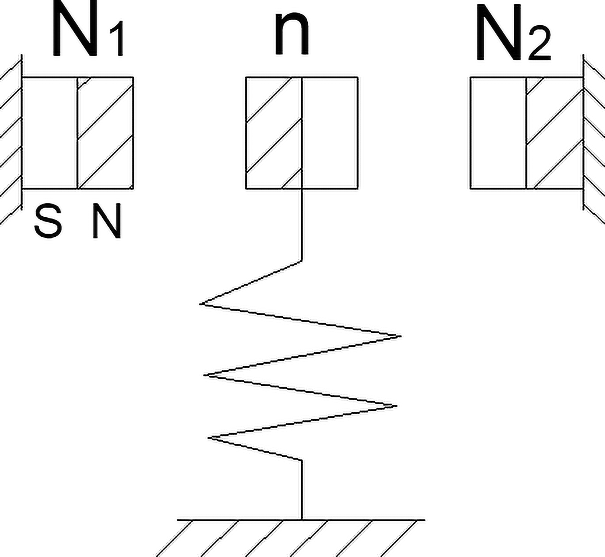
Let us make the following assumptions: It is assumed that the dimensions of two rectangular magnets m and m are 2A × 2B × 2C and 2a × 2b × 2c, respectively; The magnetic polarization intensity of the two magnets is j and J, respectively; The permeability of vacuum is μ0; There is no external magnetic field interference.
As shown in Figure 1, according to the simplified force relationship between cuboid permanent magnet models, force between M and m in the figure is as follows20,21

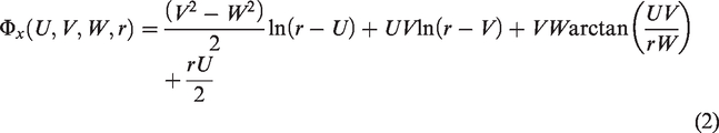


Interaction model between permanent magnets.
Negative stiffness structure based on magnetic repulsion
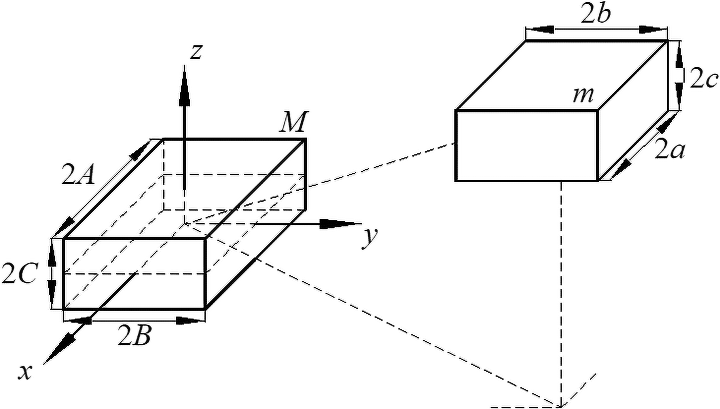
There have been some studies about NSS based on magnetic repulsion composed of triple-magnet. Now, we just analyze its basic principle briefly. As shown in Figure 2, magnets M1, M2, and m are disposed vertically in parallel, the direction of magnetic pole should ensure that m is mutually exclusive to both M1 and M2, and m is just at the midpoint of fixed M1 and M2. Therefore, m is force balanced at present. Assuming that magnet m is disturbed by external environment, it will move along the y direction out of equilibrium position and will not return itself. That means this triple-magnet structure forms negative stiffness in the y direction. Based on the definition of formula (1) and stiffness, stiffness of this structure in the y direction is as follows


Principle of triple-magnet NSS’s negative stiffness based on magnetic repulsion.
Referring to available simplified permanent magnet model,
16
we take |
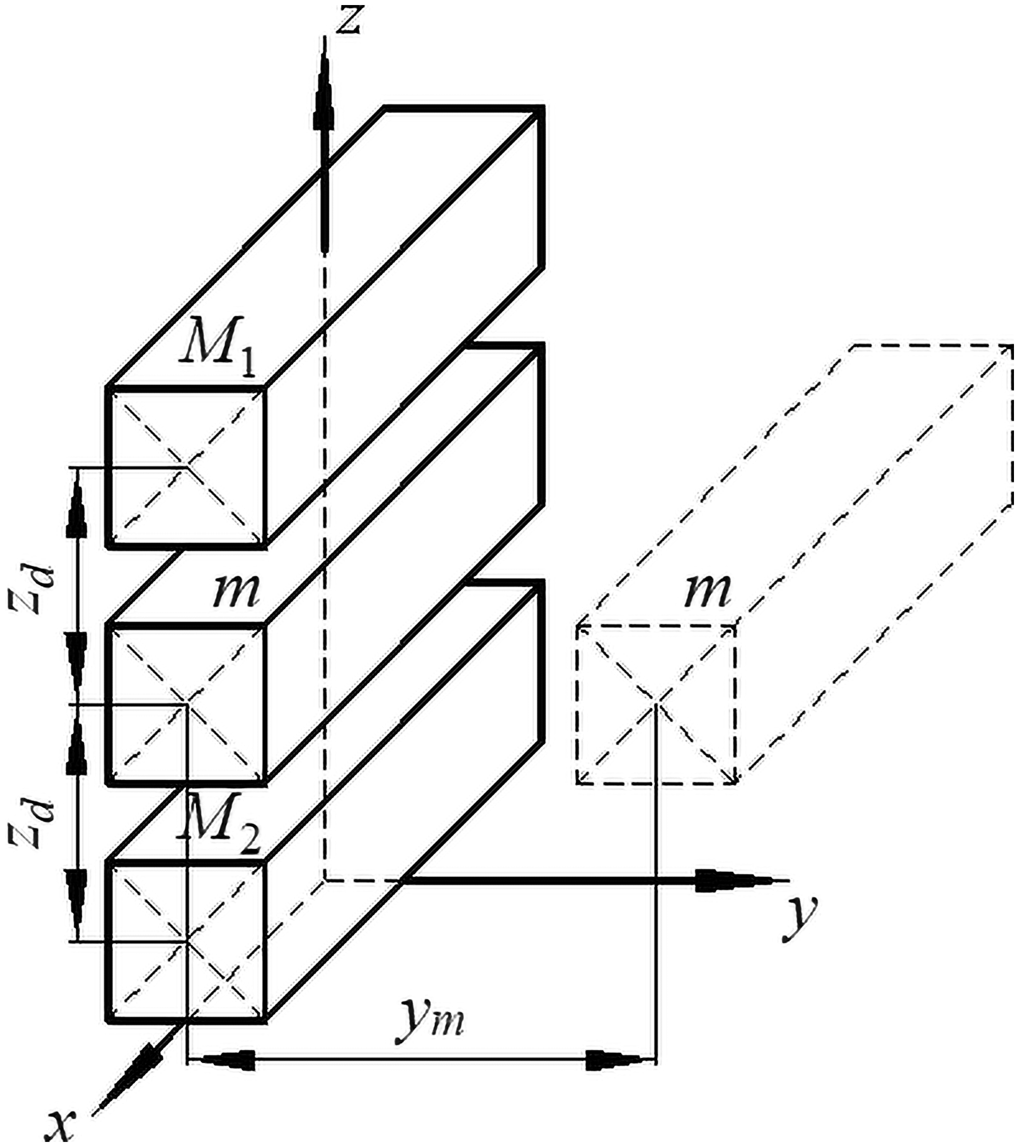
Stiffness characteristic curve.
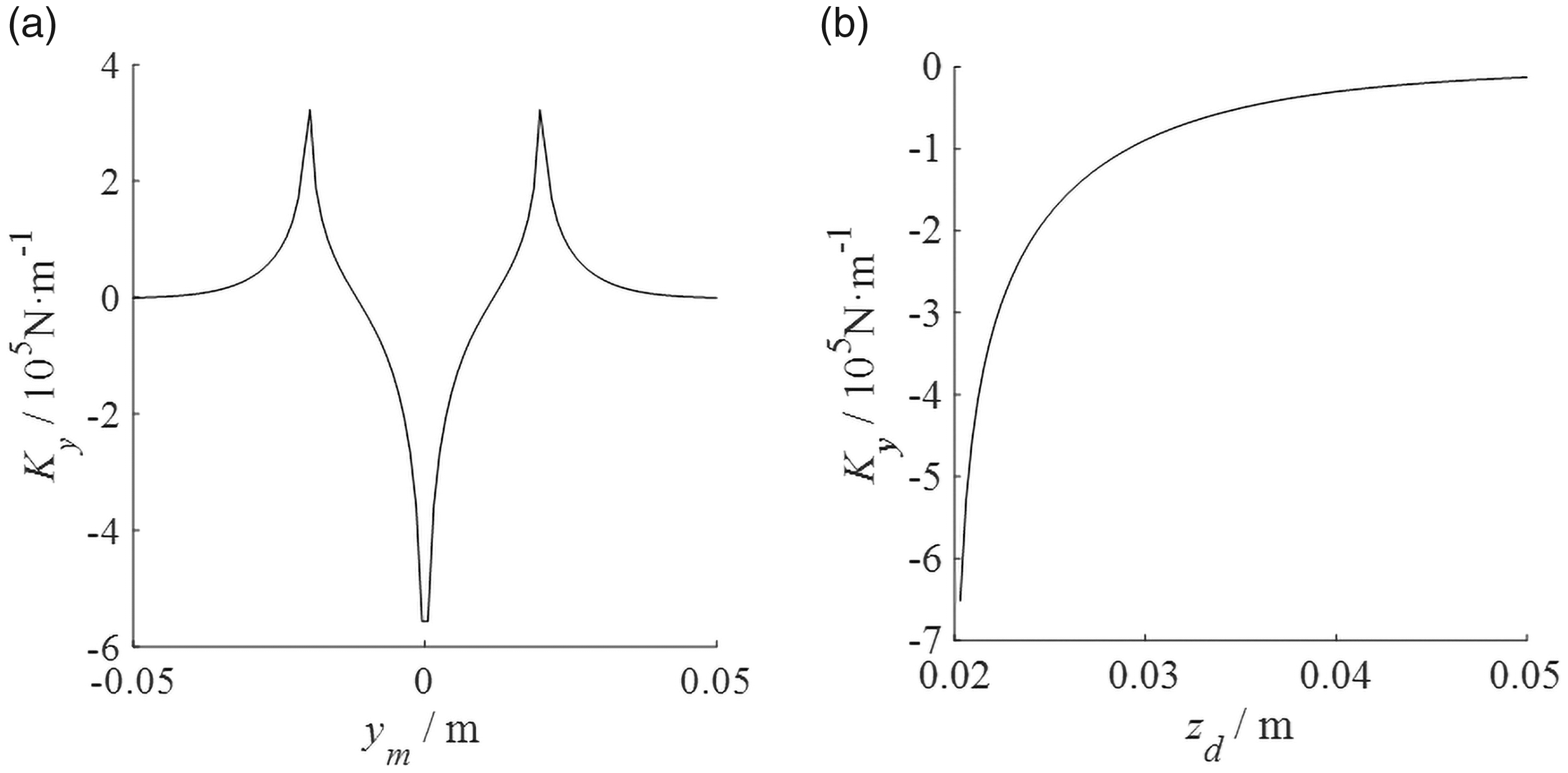
Stiffness characteristic curve (zd or ym is given).
It can be seen that if ym (m’s displacement in y direction) and zd (spacing between M and m) are given, structure’s stiffness value can be uniquely determined. Stiffness is negative near equilibrium position (|ym| = 0) and will decrease along with the increase of zd. However, stiffness value will decrease rapidly in a certain range if ym keeps increasing (following discussion in this paper is restricted to this displacement range of negative stiffness value’s monotonous change), even becomes positive, which would result in the invalidness of NSS. The greater the negative stiffness, the faster the degree of nonlinearity. Therefore, when we use this kind of structure, negative stiffness value is theoretically the maximum negative stiffness, but it can only be maintained within a very small displacement range.
The new type negative stiffness structure based on magnetic repulsion
Structure design of the new type negative stiffness structure
It was mentioned above that the parallel structure combining positive and negative stiffness equivalent to applying negative stiffness after the system have reached static equilibrium using PSS, so NSS would not affect the system’s supporting performance. Since NSS and PSS can be connected in parallel directly, total stiffness is the sum of theirs, so we could study NSS separately.
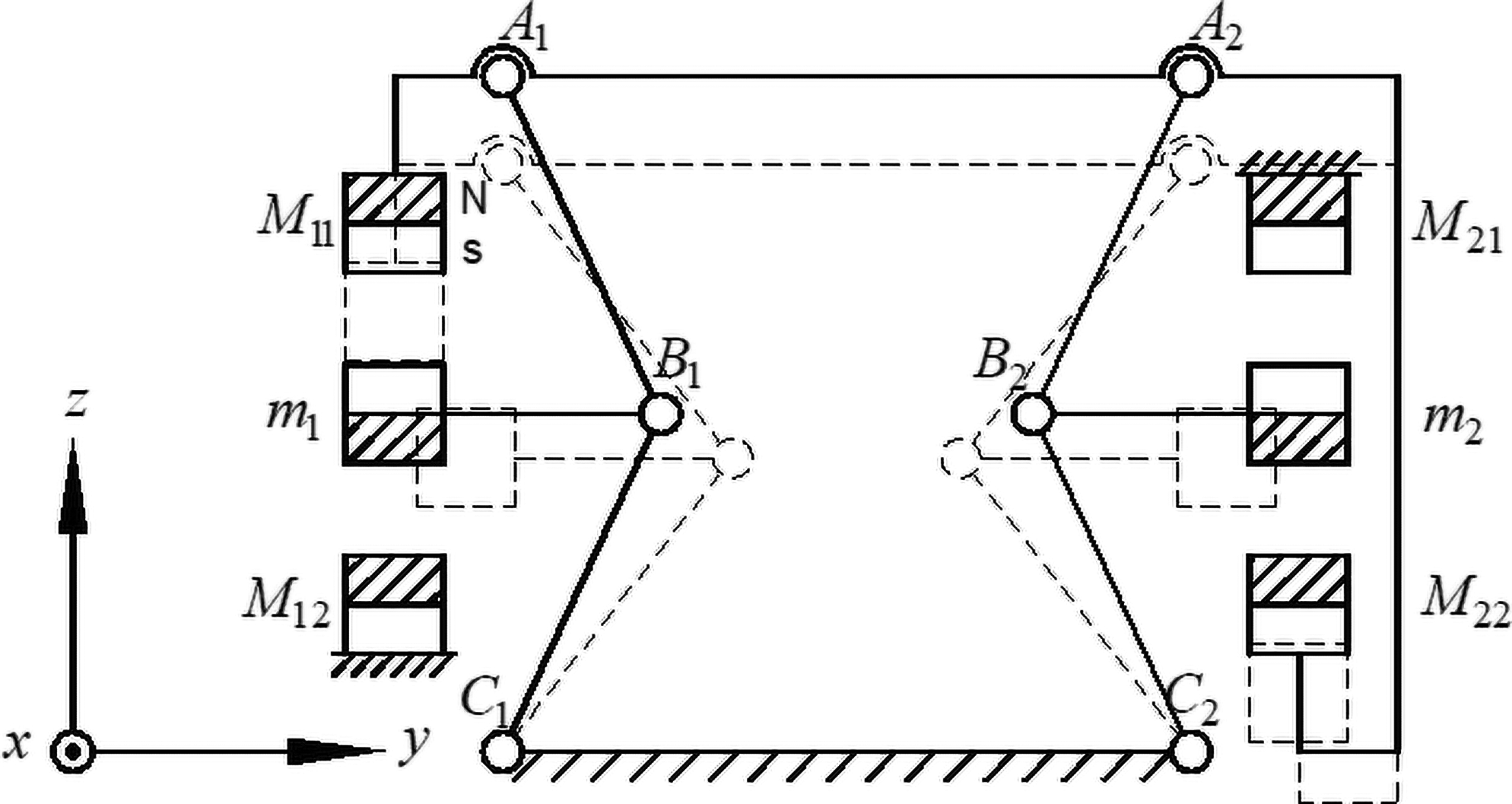
Let us consider the structure in Figure 6, which is hinged by two symmetrical negative stiffness units based on triple-magnet repulsion NSS composed of connecting rods.
In Figure 6, solid lines show the equilibrium position, where m1 and m2 are balanced. Let us assume that rod A1A2 can only translate along z direction. First, we will analyze motion in –z direction, as shown in Figure 6 by dotted lines. If there is a disturbance that makes the mechanism leave its static equilibrium position, mechanism will drive m1 and m2 to move along +y and –y direction, respectively. By conducting the mechanism, negative stiffness will finally exhibit in z direction (that means the negative stiffness is produced between A1A2 and C1C2). At the same time, M11 and M22 will move down with A1A2. Because magnetic repulsion is much larger than m’s gravity, the gravity will be ignored, and mx could stay in the middle plane between Mx1 and Mx2 because of repulsion in +z and –z directions it received. Since the motion analysis in +z direction is symmetric with the –z, we would not reiterate them here. When subjected to a vibration, the vibration energy will be gradually consumed due to the effect of damping, the vibration displacement of the middle magnet will become smaller and smaller, and finally, the negative stiffness structure will return to the equilibrium state.
Structure stiffness characteristics analysis of the new type negative stiffness structure
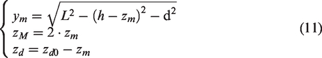
For simplicity, we only discuss the part shown in Figure 7, that is, the left-negative stiffness unit in the NSS is shown in Figure 6. Where L is the length of AB and BC and h and d are, respectively, vertical and horizontal distance between points B and A(C) when magnet m is in its equilibrium position. In the process of mechanism’s moving from solid line to dotted line, the m and A1A2 will descent, causing zd’s change. It is easy to get the relationship between zM, zm, zd, and ym according to geometric relations
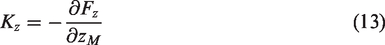
Since negative stiffness of this structure is exhibited in the z direction, we will directly calculate Kz instead of Ky here.
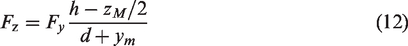
Because m has no displacement in the x direction, we can get the force Fy(zM) m received (equals to the force point B received) combining formula (1) and formula (11), and the force’s direction is horizontal-right. That means Fy can be determined entirely by zM. Then the force A1A2 received is vertical-down
According to the definition of negative stiffness, the stiffness of this structure in z direction can be obtained
In addition, due to change of zd, a dynamic stiffness Kzp is produced between M1 and M2 due to magnetic gravitation. Since the barrier of m, magnetic flux between M1 and M2 is mainly used to exclude m, and only few magnetic fluxes could produce gravitation between M1 and M2, so Kzp is often several orders of magnitude smaller than Kz and can be ignored.
In the same way, we set that stiffness of the other side of unit in this structure is K’ z. Due to the symmetry, curves of K’ z and Kz are symmetric with y axis in plane coordinates. Total stiffness of the whole structure in z direction is as follows

According to the analysis above, stiffness curve of triple-magnet NSS is the form shown in Figure 4(a) because zd is fixed, that means stiffness value is determined entirely by ym, and the curve always changes symmetrically about equilibrium position. But, for our new type of NSS’s negative stiffness unit shown in Figure 7, Ky is affected by both ym and zd. If we still use the coordinate system in Figure 6, we may find that when m moves toward +y direction, |ym| will increase, that means m will move away from M1 and M2, which would decrease the value of Ky. But zd will decrease at the same time, that means M1 and M2 will move close to each other, which would increase the value of Ky. On the contrary, when m moves toward y direction, |ym| will also increase, making Ky decrease. At the same time, zd will increase, which would decrease Ky even further. If we could make zd dominate Ky’s change of this kind, we may make Ky curve monotonously increase or decrease in a certain range and then change Kz curve similarly. If curve of Kz and K’ z could be kept linearly increasing or decreasing, negative stiffness K (equals to sum of Kz and K’ z) of the whole structure could stay stable, as shown in Figure 8. For the purposes above, structural parameters need to be concretely designed.
Parameter design of the new type negative stiffness structure
Influence of structural parameters on stiffness value
In order to obtain the ideal monotonous curve and more stable negative stiffness value in a longer stroke, it is necessary to adjust parameters of the structure. Therefore, we need to understand the influence of structural parameters on the characteristics of our NSS, finding out and analyzing the relatively important parts among these factors.
First, let us analyze the influence of magnets’ size on stiffness curve. For simplicity, our discussion is all about the triple-magnet NSS (that is the structure in “Negative stiffness structure based on magnetic repulsion” section) because our new type of NSS is actually based on triple-magnet structure. If we change dimension A or C of magnets with the size of 200 mm × 20 mm × 20 mm in triple-magnet structure, we may find that different magnet sizes in x direction do not change the shape of Ky curve essentially, and they can only change its value. Figure 9 shows that the Ky curve with α = A/a or γ = C/c equals to 2 when magnet sizes in other directions stay unchanged.
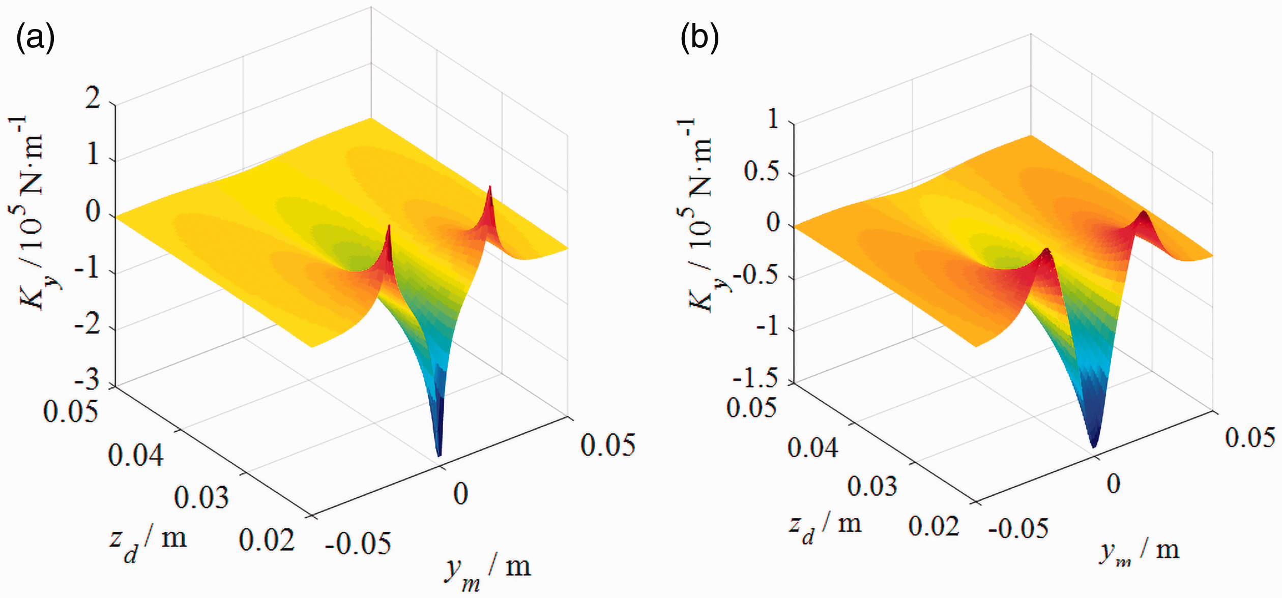
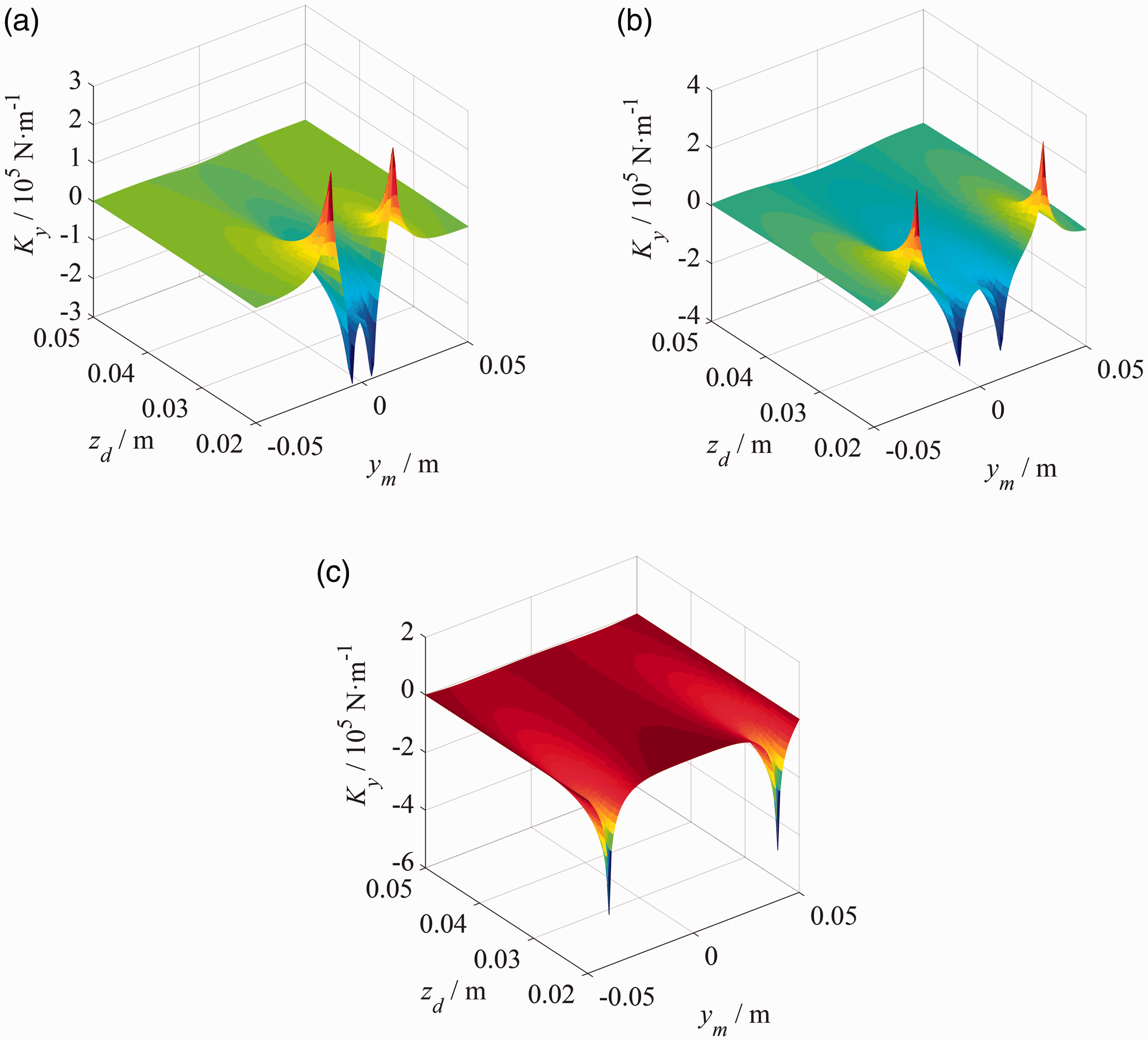
Therefore, magnet sizes in y direction are mainly considered. We take β = B/b = 0.5, 2, and 5, respectively, by changing B’s value and then draw images of Ky. It is found that when sizes of M1 and M2 in y direction deviate from that of m, negative stiffness curve will have appearance of “double-peak,” that means the maximum of negative stiffness will no longer appear in the equilibrium position, but appear symmetrically in a certain stroke, that is to say, there will have two maximum of negative stiffness value, and the rest characteristics are the same as before. When values of β and zd are suitable, Ky curve between two peaks is still negative and can remain relatively gradual within a long stroke. We find that the characteristic in this stoke is in accord with the requirements that our new type of NSS needs because ym’s influence on Ky is much weaker at this time, so zd could dominate Ky’s change now, see Figure 10 for stiffness curve with different β.
Second, let us talk about the reference distance zd0. According to stiffness curve, we know that negative stiffness value and curve’s nonlinearity could be reduced by increasing zd. If we want to make the structure work at the condition that smaller zd is smaller to reduce Kz, we could take a smaller zd0 accordingly.
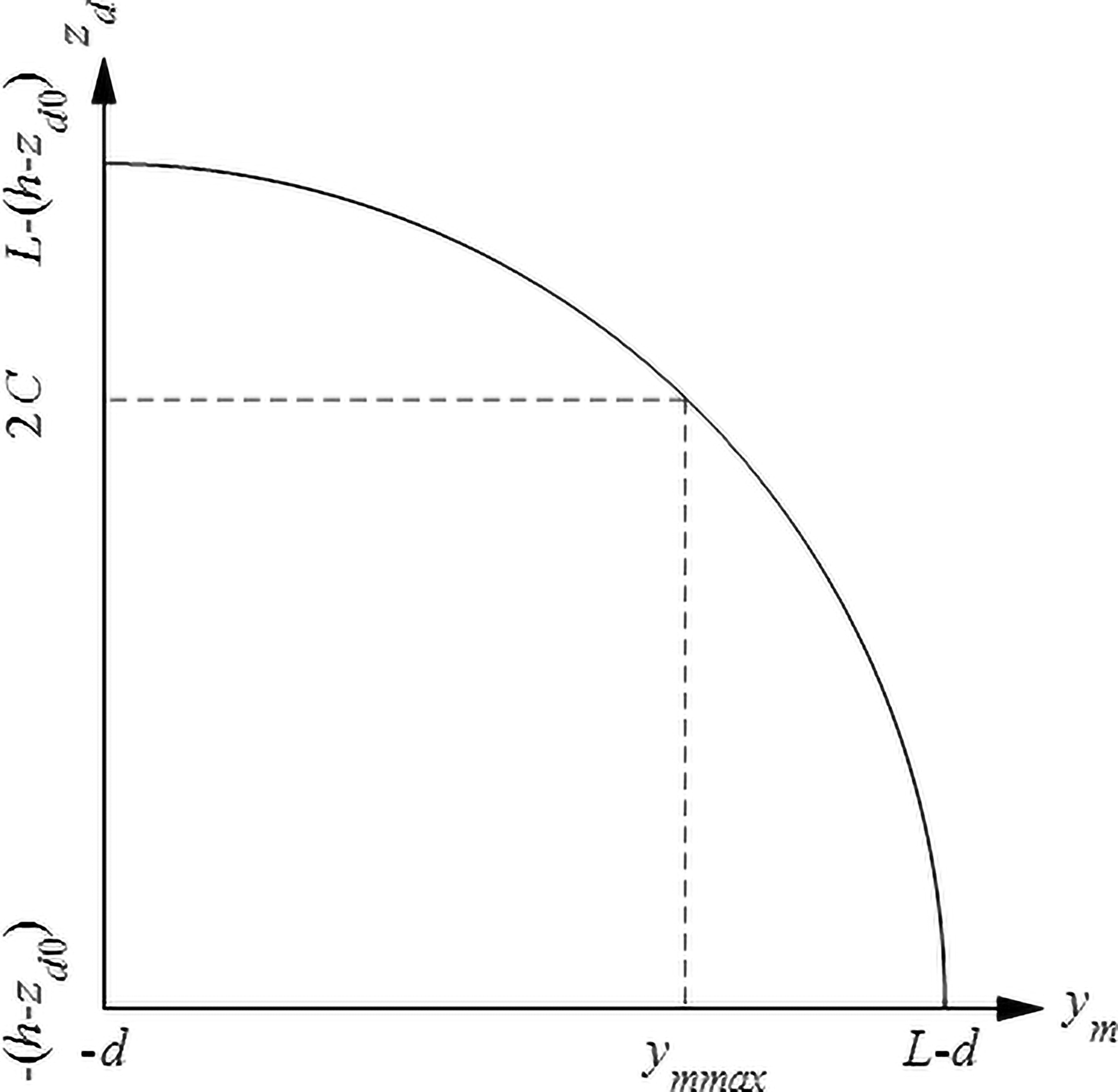
Finally, we will analyze the transmission mechanism which parameters include L, h, and d. But when L is fixed, d could be determined by h, so we set h as main parameter. By using formula (11), we can get Figure 11 showing the relationship between ym and zd, where
After obtaining the relatively stable curve of stiffness, negative stiffness value could be adjusted by selecting appropriate parameters.
Structural parameters design example of the new type negative stiffness structure
Now, we take the value that a simple triple-magnet NSS with all magnets’ size of 200 mm × 20 mm × 20 mm can produce as our target and design parameters of the new type of NSS based on this triple-magnet NSS.
As a comparison, form of the triple-magnet NSS is shown in Figure 5, and its negative stiffness is produced by three magnets in Figure 5.
Schematic structure diagram of the existing typical triple-magnet NSS based on magnetic repulsion.
Schematic structure diagram of the new type of NSS based on rectangular magnet.
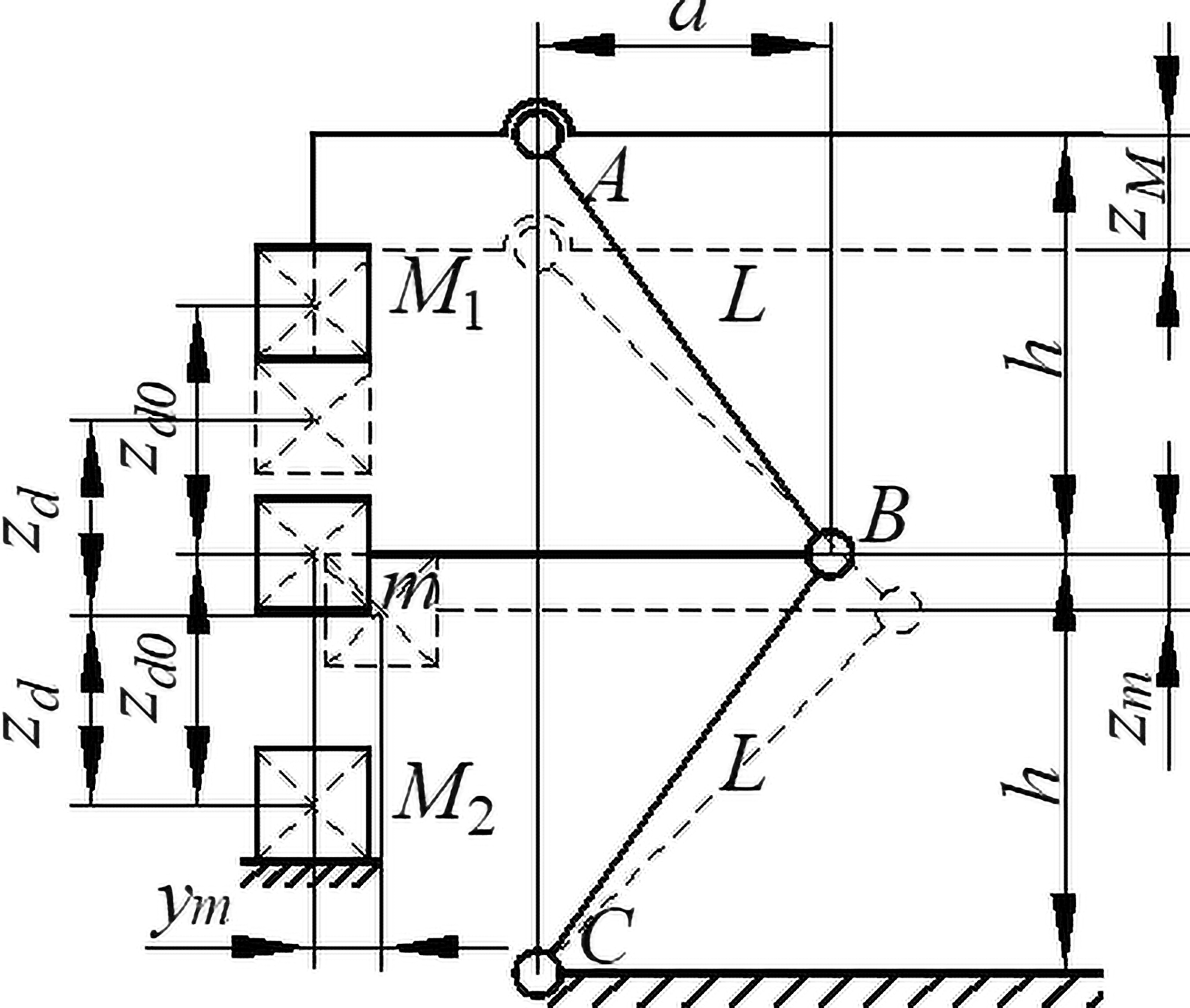
Analysis of new type of NSS’s negative stiffness unit.
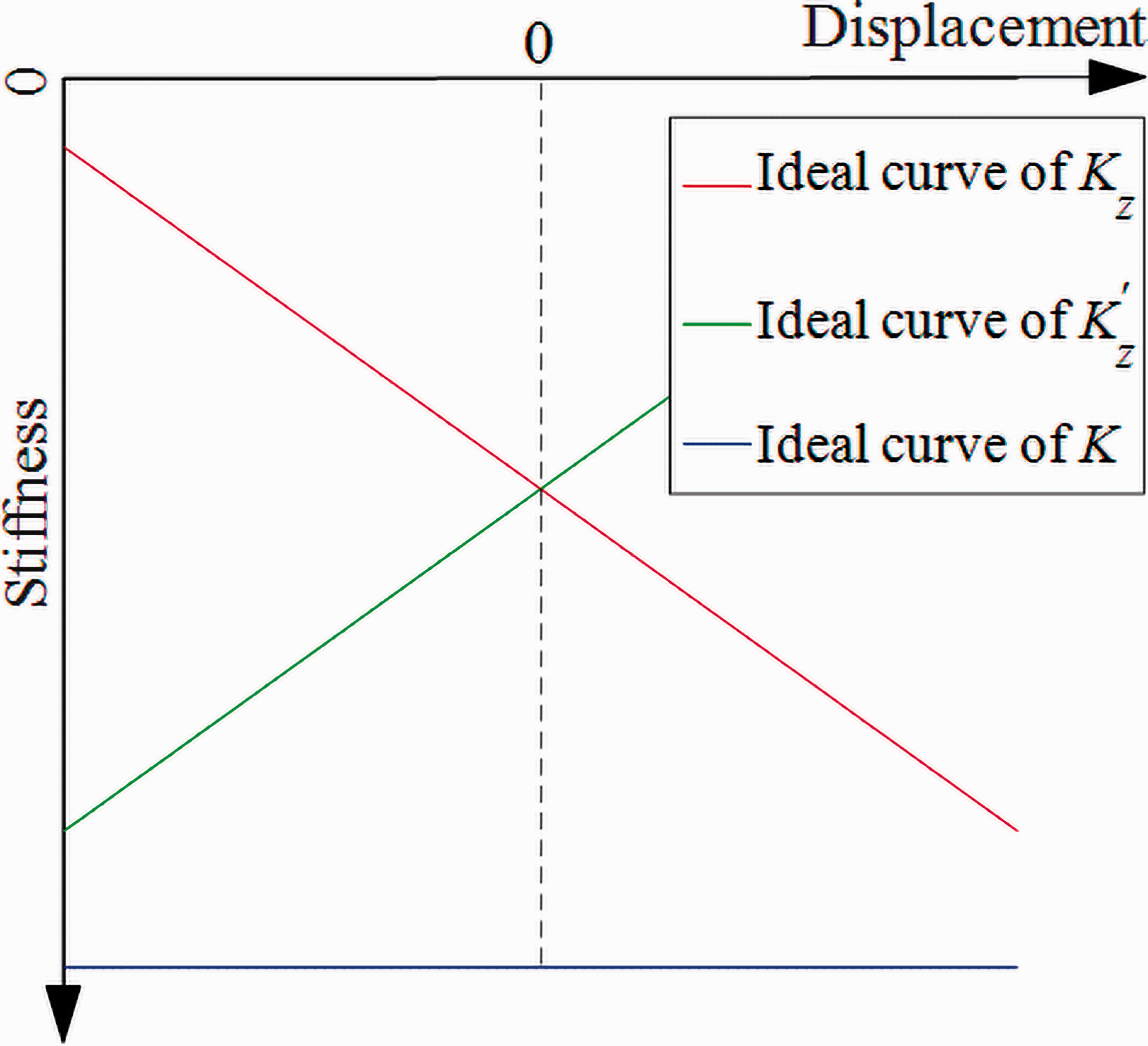
Ideal curve of Kz, K’ z and K.
It was time to design the NSS. First of all, in order to decrease nonlinearity and ensure stiffness curve’ monotonous transformation, zd0 was initially set to 50 mm. It was calculated that the maximum negative stiffness of simple triple-magnet NSS mentioned above under such condition is –1.2535 × 10⁴ N/m. Like we did above, we will analyze negative stiffness Kz of one side of negative stiffness unit in the new type of NSS first, then we could get negative stiffness K′ z of the other unit. Since the total stiffness K = Kz + K′ z equals to sum of stiffness of each side, we would like to compare the negative stiffness value average to each unit of the new type of NSS (that is K/2) with the target value.
As the transmission mechanism is easy to keep stable if working displacement is smaller relative to size of the mechanism, L and h were set to 250 mm and 200 mm, respectively, after considering comprehensively. In view of nonlinearity of the mechanism’s input and output, it is easier to analyze K curve directly. Using our analytical approach above, we could establish the new type of NSS model accordingly and get curve of its stiffness K varying with zM. Figure 12 shows the K curves with different β values (changing sizes of M11, M12, M21, and M22 with m1 and m2’s fixed). We could see that different β will lead to different K value and its linearity. In order to obtain good linearity and keep negative stiffness value in line with our target value, the β = 3 was selected. So, sizes of M11, M12, M21, and M22 could be set as 200 mm × 60 mm × 20 mm.
Accordingly, the total stiffness of K’s curve is shown in Figure 13. We could find that K is slightly larger than the target value, so values of h and zd0 should be adjusted properly, and structural parameters were finally obtained: sizes of M11, M12, M21, and M22 were 200 mm × 60 mm × 20 mm, sizes of m1 and m2 were 198.8 mm × 20 mm × 20 mm, h = 210 mm, and zd0 = 57.2 mm. The adjusted total stiffness K curve is shown in Figure 14.
Compared with simple triple-magnet NSS, the stiffness curves are shown in Figure 14. Table 1 lists the detailed negative stiffness values and errors of these two structures at different stroke.
Comparison of specific negative stiffness values and errors between two kinds of structures under different displacement conditions.
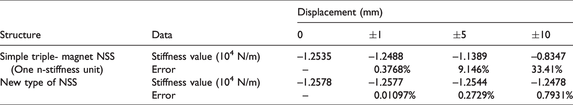
It can be seen that the new type of NSS’s negative stiffness value can approach the target value well. When displacement is relatively long, negative stiffness of the simple triple-magnet structure could not keep stable; in fact, if displacement is more than 1 mm, negative stiffness would decrease rapidly, resulting in loss of the original characteristics of the structure. However, errors of the new type of NSS are much lower than that of the triple-magnet structure; especially when stroke is ±5 mm and ±10 mm, errors decrease from 9.15 and 33.41% to around 0.27 and 0.79%, respectively. Therefore, the new type of NSS could greatly increase allowable working displacement range and provide higher stability under a given working displacement, see Figure 15 for comparison of negative stiffness stability between the triple-magnet structure and the new structure.
Of course, although the maximum allowable working displacement and stability of the new type of NSS are greatly improved compared with the simple triple-magnet NSS, earlier, characteristic that negative value changes monotonously during |ym|’s increase as mentioned above only established in a certain range. As shown in Figure 4(a), the new NSS also has a corresponding maximum allowable working displacement range that is negative stiffness value’s monotonically changing range with increasing of |ym|. The allowable range can be obtained just by observing the corresponding K–zM curve. As shown in Figure 9, allowable range is closely related to parameter β.
Stiffness curve with α = 0 or γ = 0.
Stiffness curve with different β.
Schematic relational curve of zd-ym.
K curve with different β.
Stiffness curve after preliminary design.
Final stiffness curve after adjustment.
Comparison of negative stiffness stability between the triple-magnet structure and the new structure.
Conclusion
In this paper, a new type of NSS based on magnetic repulsion is proposed by analyzing stiffness curve and characteristics of the simple triple-magnet NSS. Results show that the new NSS based on magnetic repulsion can obtain required negative stiffness value and reduce nonlinearity of negative stiffness value compared with original simple triple-magnet NSS. Thus, working displacement range of NSS can be greatly extended and stability of which can be improved. Keys to achieve the desired effect are the “double-peak” characteristic when size scale β in displacement direction is not equal to 1 and the design of structure. Because of the structure’s characteristics, it is found that there is a relatively gradual interval between two peaks of negative stiffness curve when an appropriate β values, which could keep stiffness curves of both sides increasing and decreasing monotonously, so the sum could keep stable. Although it is difficult to guarantee the structure’s ideal symmetry in engineering practice, keys to approximate linearity of negative stiffness are structure’s arrangement and motion characteristics, so asymmetry during installation and operation will mainly affect the value of negative stiffness and reduce allowable working displacement range of the structure, which will not have a great adverse effect on whole property. Reference spacing zd0 and structural parameters L, h, and d will also affect negative stiffness of the structure. Since a larger zd0 means a larger zd when the structure is working and increasing zd can reduce negative stiffness and nonlinearity of the curve, a smaller zd0 can be taken to reduce Kz’s value or nonlinearity of negative stiffness. When L is certain, h’s increase will decrease the nonlinearity of negative stiffness value and increase the Kz’s value. Effect of d is opposite to that of h. The new type of NSS also has a corresponding maximum allowable working displacement. Since the monotonous variation of the triple-magnet NSS’s negative stiffness with |ym|’s increasing only established in a certain range and the new type of NSS is formed by two symmetrical units based on triple-magnet NSS, the maximum allowable displacement cannot exceed this range, and if it does, reliability of the whole structure cannot be guaranteed.
Footnotes
Declaration of conflicting interests
The author(s) declared no potential conflicts of interest with respect to the research, authorship, and/or publication of this article.
Funding
The author(s) declared the following potential conflicts of interest with respect to the research, authorship, and/or publication of this article: This research work was supported by the National Natural Science Foundation of China (Grant No. 51705117) and the Fundamental Research Funds for the Central Universities (Grant No. JZ2019HGTB0087, No. PA2020GDSK0073).