
Abstract
To solve the problem of large operating noise of existing pyrotechnic separation devices, a new low-noise pyrotechnic separation device is designed by changing the utilisation mode of pyrotechnic separation, using micro gas pyrotechnic as heat sources, and shape memory alloy material to convert heat energy into mechanical energy. The results showed that the separation time was 1.526 s when the preload was 20 kN, and the maximum shock response was 319 G (2268 Hz) for 100 Hz–100 kHz. When used underwater, the maximum sound pressure level is 106.9 dB at 12,698 Hz and 98.5 dB from 10 Hz–5 kHz. Compared with a conventional separation nut, the frequency band sound pressure level can be reduced by more than 70 dB, realising underwater low-noise separation.
Keywords
Introduction
Explosive bolts and separation nuts are widely used in aerospace, missile weapons and underwater vehicle separation systems,1,2 using the energy driving mechanism of a charge explosion or combustion to complete specific functions. The advantages of pyrotechnic separation devices are large energy storage, fast action speed, simple and compact structure, and small trigger energy. However, a pyrotechnic separation device involves the combustion or explosion of energetic materials, the motion collision of the mechanism.3–6 When an underwater vehicle is used to conduct load separation, throwing, unlocking or other actions, the noise of the triggering action exceeds the requirements for low-noise actuation of the separation device. The main method of reducing the pyrotechnic separation system noise is to reduce the charge. However, the power source of a pyrotechnic separation device is a transient high-temperature and high-pressure gas produced by the explosive or the rapid combustion of gunpowder; noise reduction is limited, and the separation reliability of the pyrotechnic separation device is affected. The separation noise can only be controlled at 150–160 dB,7,8 which does not fully meet the underwater vehicle requirements.
In view of the shortcomings of pyrotechnic separation devices, research has been conducted on non-explosive separation devices. At present, non-explosive separation devices mainly include polymer driving devices, thermal cutting devices, electric drive reel devices and shape memory alloy (SMA) deviees.9-13 Separation mechanisms based on SMA offer simplicity, repeatability, adjustability and unique material characteristics. They have been used in aerospace14,15 as an alternative to pyrotechnic separation devices. Moreover, SMA intelligent material replaces the pyrotechnic trigger or driving source. Shape memory alloy can reduce separation shock and noise at the source, and meet the requirements for spacecraft and underwater vehicles. However, with a large excitation energy and small bearing capacity, the application of non-explosive separation devices is limited.
Addressing the problems in the application of pyrotechnic separation devices and non-explosive separation devices, this study combines their advantages to design a low-noise pyrotechnic separation device. By changing the energy utilisation mode of the pyrotechnic separation mechanism, a pyrotechnic composition with a fast burning rate and micro gas production is used as the heat source, with SMA material to convert heat energy into the driving force for the mechanical movement of the separation device. As the pyrotechnic composition is not used as the driving source, the problem of high separation shock and separation noise is solved at the source; low-noise separation is realised.
Study on combustion noise suppression method of pyrotechnic separation device
Analysis of noise generation mechanism of pyrotechnic separation device
Conventional pyrotechnic separation devices involve combustion or explosion of energetic materials, a motion collision of the mechanism and the release of strain energy in the process of work to produce high-frequency and high-amplitude pyrotechnic shock and separation noise. As an example, a reverse push-type separating nut is shown in Figure 1 and Ref. 16. With the limiting effect of the shear pin and spring, the inner sleeve maintains a radial constraint on the nut flap in the ground operation and launching stages to obtain a reliable connection. After receiving the separation instruction, the pyrotechnic composition located in the housing ignites and detonates immediately producing a high-temperature, high-pressure gas that fills the housing chamber that drives the inner sleeve to move, cutting the shear pin and compressing the spring. The threaded segment is released when the inner sleeve moves to a certain stroke; the threaded segment begins to expand radially, releasing the constraint on the bolt. The bolt flies out under the action of preloading to complete the separation. Diagram of reverse push-type separating nut.
According to the structure and actuating process of the pyrotechnic separation device, it can be seen that the pyrotechnic separation device is a sealed structure, and there is no material exchange with the outside world, only energy exchange with the outside world. Therefore, the actuating noise of the pyrotechnic separation device is the noise radiated to the outside world by the combustion of energetic materials inside the separation device and the vibration of the shell surface caused by the mechanical movement of components. The generating mechanism of the noise is shown in Figure 2. Mechanism of noise generation in actuating process of pyrotechnic separation device.
According to the different excitation force, the operating noise of the pyrotechnic separation device mainly includes the combustion noise of energetic materials and mechanical noise. 1. Combustion noise of energetic materials
In the pyrotechnic separation device, the combustion noise of energetic materials is one of the most important noise sources. The sound mechanism of the combustion noise of energetic materials is quite complicated, and the main reason is the gas in the combustion chamber during the combustion of energetic materials. The drastic changes in pressure and the unsteady flow of combustion products cause the surface of the pyrotechnical separation device to vibrate, thereby radiating noise to the outside world, which is flow-induced vibration noise. 2. Mechanical noise
Mechanical noise is the noise generated by the collision between the moving parts of the pyrotechnic separation device to excite the vibration of the housing of the pyrotechnic separation device. It mainly includes the noise generated by the collision between the inner sleeve, the separation nut, the piston, the outer shell and other components, and the noise caused by the pin fracture during the operation of the separation device.
Among them, for mechanical noise, it is easy to reduce the impact noise by designing cushioning pads and replacing different materials, 6 while for the combustion noise of energetic materials, limited by the actuating principle of pyrotechnic separation device, there is no better noise reduction measures at present. Under the condition that the energy conversion mode of the energetic material in the existing pyrotechnic separation device is unchanged, the actuating noise in the actuating process of the pyrotechnic separation device can be reduced to a certain extent by reducing the charge quantity and gas pressure of the energetic material. However, since the pyrotechnic separation device mainly uses the high-temperature and high-pressure gas generated by gunpowder combustion to unlock and separate, there is a minimum reliable starting pressure, so the effect of reducing the actuating noise of the pyrotechnic separation device by adjusting the energetic charge and gas pressure is limited. 17
Design principle of triggering component of SMA tube
In view of the shortcomings of pyrotechnic separation devices, research has been conducted on replacing the pyrotechnic separation device power source with a non-explosive separation device. Non-explosive separation devices based on SMA are currently popular in research. Shape memory alloy is an alloy material that can completely eliminate deformation at low temperatures after heating to recover the original shape. Owing to the shape memory effect, these alloys are often used in sensors and actuators in the form of wires, springs, sheets, tubes or cylinders.18,19 Using direct electrified heating, SMA wire and SMA spring drives act quickly, but the separable load is relatively small. The axial drive of an SMA rod or SMA tube can release the maximum load to meet the demand of large load separation. However, the external electric heating method for an SMA tube does not meet the requirements for low energy consumption and rapid separation.
In this study, combining the advantages of pyrotechnic separation and non-explosive separation devices, based on the structure of the reverse push-type separation nut (Figure 1), the method of using gunpowder in the separation device is changed. An SMA tube replaces the shear pin and spring to realise the limit of the sleeve, and a compression spring replaces the gunpowder gas as the driving source. An SMA tube trigger assembly was designed, as shown in Figure 3. The assembly consists of an igniter, an SMA tube, a pyrotechnic composition and a plug. Before ignition, the outer wall of the SMA tube bulges to limit the axial movement of the locking sleeve. When the actuator is activated by the external current, the pyrotechnic composition in the tube is ignited by the igniter. The heat energy generated by the combustion of the pyrotechnic composition heats the SMA tube above its phase transition temperature through thermal radiation and heat conduction. When the SMA pipe diameter shrinks, the axial constraint of the locking sleeve is released; the locking sleeve moves axially under the driving force F of the spring to complete the trigger operation. Because the SMA trigger assembly does not need energetic material to provide driving force, the production of high-temperature and high-pressure gas can be avoided, and the combustion noise of energetic material can be reduced at the source. In addition, compared with the non-pyrogenic connection separation device, the SMA tube trigger assembly has a smaller excitation energy, and its energy conversion process is shown in Figure 4. Structure and radial driving principle of SMA trigger assembly. (a) Before ignition, (b) After ignition. Energy conversion mechanism of SMA tube trigger assembly.
Pyrotechnic composition
In order to reduce the noise generated by the combustion of energetic materials, on the basis of ensuring the rapid heating of SMA tube, the production of high-temperature and high-pressure gas is reduced, so as to avoid the radiation noise generated by the shell vibration stimulated by the unsteady flow of combustion products in the process of the combustion of energetic materials, so as to realise the purpose of low-noise operation. Therefore, it is required that energetic materials have the characteristics of micro gas production, high heat production and fast burning rate.
Silicon-based delay grain is a type of micro gas delay composition, with a high combustion heat value and fast burning rate. It is used as the pyrotechnic composition for the trigger assembly and is mainly composed of Si, Pb3O4, Sb2S3 and Se. The combustible agent is silicon powder, the oxidant is red lead, antimony sulphide is used for dilution and retarding combustion, and selenium powder is an additive to improve the delay accuracy. According to the combustion reaction mechanism of the Pb3O4/Si/Se ternary system, the following reactions20,21 take place in the grain


The total reaction equation is

In this reaction, solid–solid reactions and solid–gas reactions occurred simultaneously. In the initial stage of the reaction, the oxygen atoms in Pb3O4 diffuse to produce free oxygen, a reaction of the atoms occurs on the surface of the redox agent particles, and the oxide formed adheres to the surface of the reducing agent. At approximately 500°C, Pb3O4 begins to decompose, and the reducing agent continues to oxidise. The composition of the silicon-based delay grain used in this study is Si/Pb3O4/Sb2S3/Se, the solid–solid reaction is predominant; the proportion of solids in the combustion products is approximately 96%, which meets the requirements of this study.
Design principle of low-noise pyrotechnic separation device
Structural design principle
Based on the SMA tube trigger assembly and the structure of the reverse push-type separating nut, a new low-noise pyrotechnic separation device is designed; a diagram is shown in Figure 5. Before ignition, the axial constraint of the locking slider is provided by the bulge on the outside of the SMA tube; the radial restraint of the threaded segment is provided through the boss of the sliding block and threaded segment to limit the radial opening. Low-noise pyrotechnic separation device. (a) Before ignition, (b) After ignition.
After receiving the separation instruction, the pyrotechnic composition in the SMA tube ignites, and the high-temperature generated by the combustion of the pyrotechnic composition heats the SMA tube. When the temperature of the SMA tube exceeds the SMA phase transition temperature, the diameter of the SMA tube decreases and the axial constraint on the locking sleeve is released. Under the action of the drive spring, the locking sleeve moves axially until the locking sleeve and the threaded segment bosses are separated from each other. Under the action of preload and the release spring, the threaded segment opens radially and releases the connecting bolt to separate the connectors.
Design of unlocking components
The unlocking components consist of a threaded segment, a locking sleeve, a supporting sheath, an end cover and a drive spring.
Locking sleeve: Limits radial movement of threaded segment.
Supporting sheath: Limits the axial movement of the threaded segment and positions the threaded segment during installation.
End cover: Limits the axial movement of the threaded segment and guides the threaded segment when it is separated.
Drive spring: To release the radial constraint of the threaded segment, the sliding friction between the locking sleeve and the threaded segment must be overcome during the operation and is the key element determining whether the separation device can be reliably separated. The driving force of the drive spring is determined through mechanical analysis of the threaded segment. A simplified model of the threaded segment is taken as the analysis object; mechanical analysis is conducted in the locked state, as shown in Figure 6. Force analysis of threaded segment.
It is observed in the force balance that


Because the release spring-driven separating ejector only separates the petal nut, which has lost its radial restraint, the required elastic force is small; thus, N
2
can be ignored. The friction force F
f
between the locking sleeve and the threaded segment during the actuation process can be expressed as

Threaded segment design parameters.
Strength check of SMA tube
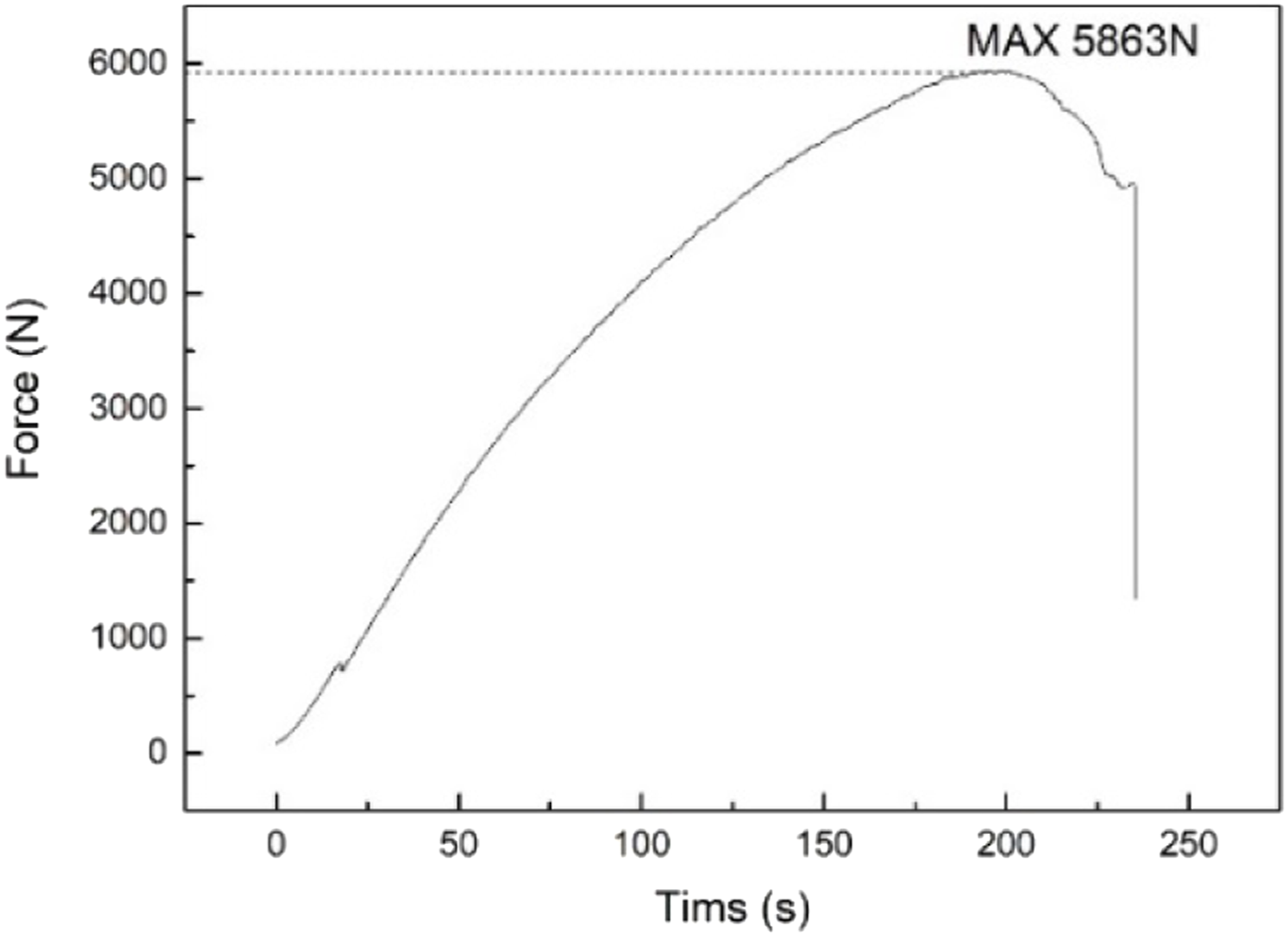
The maximum axial load of the SMA tube determines the maximum driving force of the drive spring and indirectly determines the maximum separation load of the separation device based on the SMA tube. In this study, the bearing capacity of the SMA tube is tested using a material tensile testing machine. The test principle and test site are shown in Figure 7. During the test, the displacement load was applied at one end of the SMA tube at a speed of 1 mm/min; the stress change curve during the loading process was recorded by the acquisition instrument, as shown in Figure 8. The maximum axial driving load that the SMA tube can bear is 5863 N, which is greater than the driving force of the drive spring (1928 N) and meets the strength requirements of the SMA tube. Bearing capacity test setup for SMA tube. Bearing capacity test curve for SMA tube.
Function and underwater actuation noise test
Function test
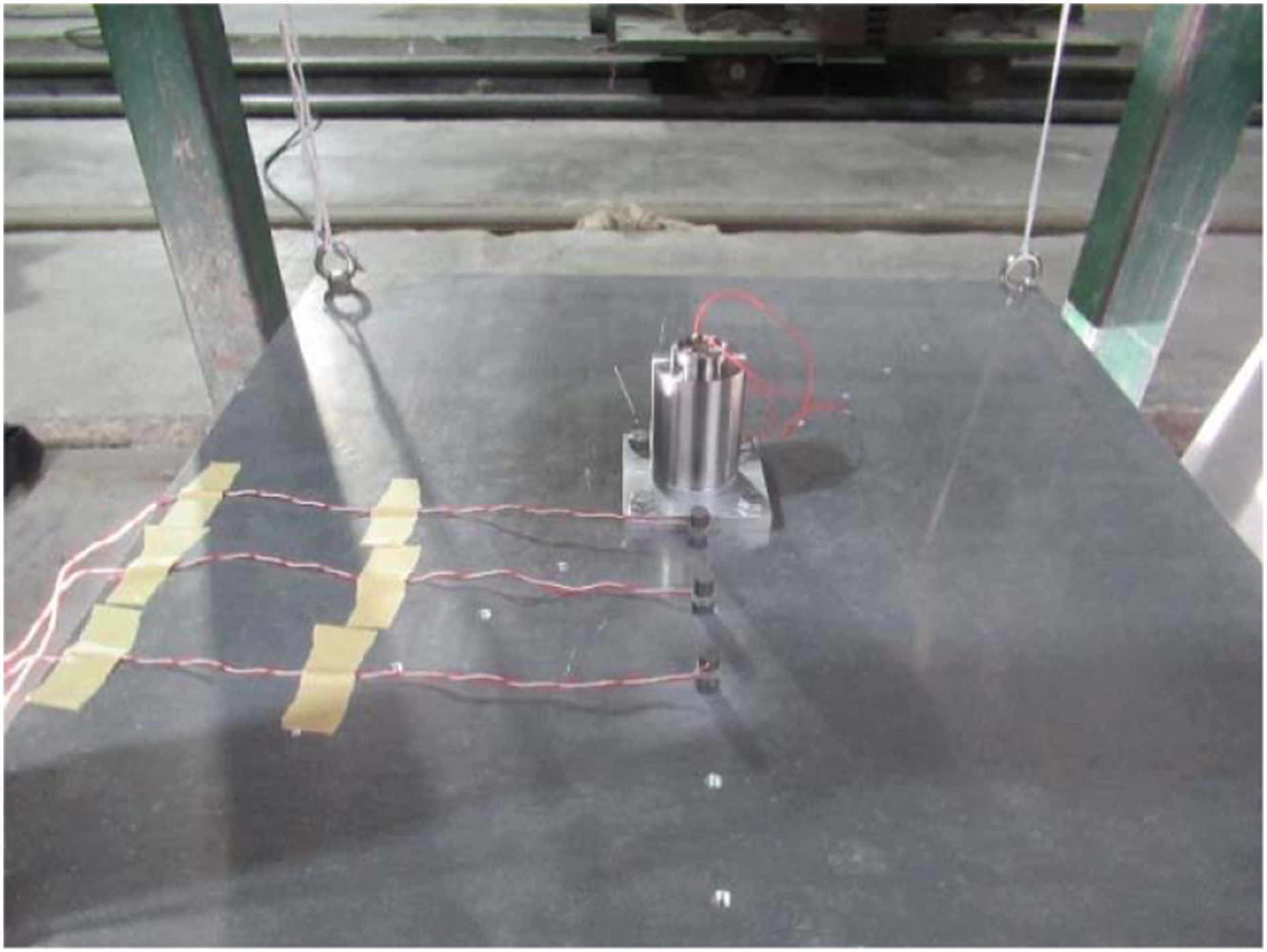
To measure the separable load, separation time and separation shock of the low-noise pyrotechnic separation device, a set of dynamic multi-parameter synchronous test systems was constructed, as shown in Figures 9 and 10. An acceleration sensor was used to measure the separation shock, and a ring force sensor was used to detect the application and release process of the preload. The pyrotechnic separation device was installed in the centre of a 2A12 aluminium alloy plate with dimensions of 60 cm × 60 cm × 1 cm. The four corners of the plate were suspended with four nylon ropes to simulate weightlessness. Piezoresistive acceleration sensors A1, A2 and A3 (PCB 3501b1260 kg) were installed in three different positions on the board. The response amplitude can reach ±60 kG, the frequency range is 0–20 kHz (±1 dB), the lateral sensitivity is less than 3% and the resonant frequency is greater than 120 kHz.
24
The distances from the centre were 5 cm, 10 cm and 15 cm, respectively. A ring force sensor was placed between the response plate and lock nut. The measurement range of the ring force sensor was 35 kN, the nonlinearity was less than 1%, the resonance frequency was greater than 60 kHz and the sampling rate of the signal collector was 50 kHz. During ignition, the ignition controller gives the ignition signal to the igniter. The data acquisition system obtains the trigger signal and starts to work. Three acceleration sensors record the vibration signals at different positions, and the ring pressure sensor records the changes in preload, which are transmitted to the data acquisition instrument after signal conditioning. Diagram of low-noise pyrotechnic separation device separation performance test system. Test site of low-noise pyrotechnic separation device separation performance.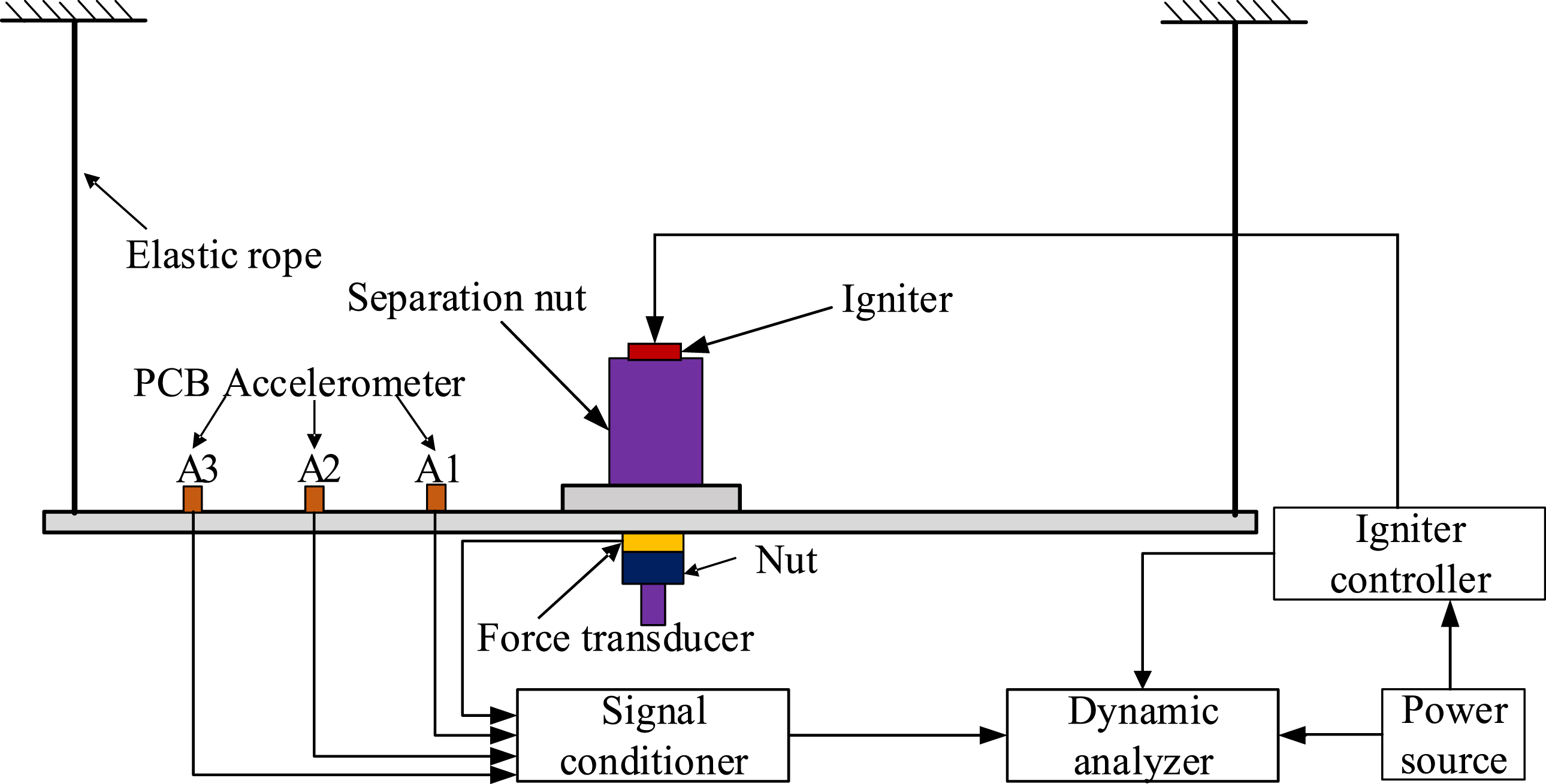
The firing current signal and preload release processes of the low-noise pyrotechnic separation devices are shown in Figure 11. Among them, t2 is the time point when the preload starts to show an obvious and continuous decrease and t3 is the time point when the preload decreases to 0. From the preload release curve, it is observed that the actuating process of the pyrotechnic separation device is divided into two stages. t1 to t2 is the triggering stage of the SMA tube. In this stage, the preload is maintained at 20 kN without obvious change; the duration of this stage is 1.294 s. t2 to t3 is the stage of unlocking and separation. In this stage, the radial constraint of the threaded segment is gradually released, the preload decreases rapidly; the preload decreases to 0 N at t3 to complete the unlocking and separation. The duration of this stage is t
3
− t
2
= 0.232 s, which is shorter than the triggering stage of the SMA tube. The main means of improving the response speed of a low-noise pyrotechnic separation device is to shorten the triggering time of the SMA tube, which improves the heating efficiency of the SMA tube. Preload release curve.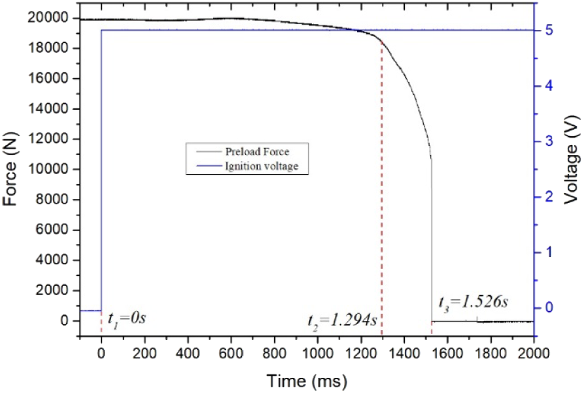
The acceleration time history characterises the shock environment. Under a load of 20 kN, the time history of the explosive device output impact acceleration is shown in Figure 12. It is observed in Figure 12 that during the separation process, there is essentially no shock during the SMA tube trigger operation stage. Its main output shock source is the separation shock generated when the preload is released, with a peak value of 117 G. The reason is that, in the triggering stage of the SMA tube, the combustion of the energetic material and the radial contraction of the SMA tube after heating are mainly carried out, and there is no high-temperature and high-pressure combustion gas in the process of the energetic material combustion, so there is no impact response to the response plate. Test curve of shock acceleration at different distances.
In the field of aerospace engineering, the shock response spectrum (SRS) is often used as the criterion for in-process product design and testing, and to evaluate the damage potential of shock. There are many methods to calculate the SRS. For the sake of calculation speed and accuracy, the improved recursive digital filtering method proposed by Smolwood in 1982 was adopted in this study.
25
The analysis frequency range is 100 Hz–10 kHz, 1/12 octave and a damping ratio of Output shock response spectrum of low-noise pyrotechnic separation device (preload 20 kN).
Underwater separation noise test
To test the underwater separation noise of the pyrotechnic separation device, the underwater actuating noise was tested in an anechoic tank. The noise of an existing underwater separation device, such as a separation nut, was tested. The underwater separation noise of the designed low-noise pyrotechnic separation device was compared and analysed, and the noise reduction effect was investigated.
The test was conducted in an anechoic tank with a length of 50 m, a width of 10 m and a depth of 5 m. The test distance was 1 m, the background noise was 80 dB and the reference sound pressure was 1 MPa. A diagram of the test system is shown in Figure 14. In this system, the B & K 8106 hydrophone, placed 1 m away at the same level as the device to be tested, converts the sound pressure signal into an electrical signal that is amplified by the B & K 2636 charge amplifier and filtered by an NF3628 digital filter. The data were collected by the PXI-4498 data acquisition system and processed using LabVIEW and MATLAB data analysis software. The frequency band sound pressure level (L
poi
) and broadband sound pressure level (L
po
) are calculated as Underwater separation noise test system.

The transient acoustic signal may be significantly distorted as a result of medium propagation and target scattering; the time averaging results are uncertain. When calculating the pulse source level, the time of pulse data processing makes the sound source level calculation result uncertain. The essence of underwater acoustic pulse separation is the instantaneous release of energy into water. This study selects data from the pulse front to the time when the waveform is submerged in the environmental noise. The pulse signal is recorded within the time interval (ISO 18,405) when the pulse energy increases from 5% to 95%,28,29 which contains 90% of the total pulse energy. In data processing, the energy can be normalised. The calculation formula for the pulse energy flow density E is expressed as
The underwater actuating noise test curves of the explosive bolt in the low-noise pyrotechnic separation device are shown in Figures 15(a) and 16(a). The pulse signals in the time interval when the pulse energy increases from 5% to 95% are shown in Figures 15(b) and 16(b). It is observed in Figure 15(a) that the noise signals appear at both ends of the low-noise pyrotechnic separation devices during underwater operation. According to the principle of a low-noise pyrotechnic separation device, the noise signals in the two stages are the noise generated by the combustion of pyrotechnic composition and the noise generated by the collision of unlocking and separating machinery when the SMA tube is triggered. Different from Figure 10, the low-noise separation device also showed strong radiation noise during the trigger stage. The reason may be that, in the underwater actuated noise test, the sound pressure sensor and the sample to be tested are in the same horizontal line, and no response plate is installed in the test. So the measured sound pressure signal is the radial radiation noise generated by the surface vibration of the shell of the separation device itself, embodied in the SMA tube trigger actuation and unlock separation phase caused by the external surface of the shell vibration of radial radiation noise as shown in Figure 15. The maximum peak values of the two stages are 0.0026 V and 0.0028 V, respectively; the noise produced by mechanical collision in the unlocking separation stage is greater than that generated by the combustion of pyrotechnics when the SMA tube is triggered. In this study, the noise signal of the unlocking and separation stage is extracted to investigate the underwater actuating noise of a low-noise pyrotechnic separation device; the sound pressure level is three orders of magnitude smaller than the underwater actuating noise of the separating nut. Low-noise pyrotechnic separation device. (a) Noise test signal, (b) Analysis section noise test signal. Separating nut. (a) Noise test signal, (b) Analysis section noise test signal.
The sound pressure power curve of the low-noise pyrotechnic separation device and explosive bolt is shown in Figure 17. In Figure 17(a), the separation noise is concentrated mainly from 10–100 kHz, and the maximum sound pressure level is 106.9 dB at 12,698 Hz, with a smaller separation noise in the range of 10–5000 Hz. For the separating nut, the frequency band range of the noise is wide. As shown in Figure 15(b), the maximum sound pressure level is 173.4 dB at 1574 Hz in the frequency range of 10–100 kHz. The underwater separation noise of the low-noise pyrotechnic separation device and separation nut are summarised in Table 2. Sound pressure power spectrum curve. (a) Sound power spectrum of low-noise pyrotechnic separation device. (b) Sound power spectrum of the separating nut. Summary of underwater separation noise test results.
From the test results, it is observed that the actuating time of the low-noise pyrotechnic separation device is larger than that of the separating nut, but the underwater separation noise of the low-noise pyrotechnic separation device is greatly reduced. Compared with the separation nut, the frequency band sound pressure level is reduced by 76 dB from 10–15 kHz, indicating that the low-noise pyrotechnics separation device design offers good noise reduction performance.
Conclusion
To address the problem of high separation impact and action noise in existing pyrotechnic separation devices, a new low-noise pyrotechnic separation device is designed by changing the utilisation mode of the pyrotechnic composition in the pyrotechnic separation mechanism, using silicon and red lead delay grain as heat sources and SMA material characteristics to convert heat energy into mechanical energy. When the load of the device is 20 kN, the separation time is 1.526 s, and the maximum internal shock response is 319 G (2268 Hz) from 100 Hz–100 kHz. According to the underwater noise test, the maximum sound pressure level of the underwater separation noise is 106.9 dB at 12,698 Hz, and the frequency band sound pressure level is 98.5 dB from 10 Hz–5 kHz. Compared with the noise generated by the separation nut, the frequency band sound pressure level is reduced by 76 dB, solving the separation noise problem of the pyrotechnic separation device at the source and realising underwater low-noise separation. The pyrotechnic separation device proposed in this study based on the energy conversion principle meets the low-noise separation system requirements for spacecraft and underwater vehicles.
Footnotes
Declaration of conflicting interests
The author(s) declared no potential conflicts of interest with respect to the research, authorship, and/or publication of this article.
Funding
The author(s) received no financial support for the research, authorship, and/or publication of this article.