
Abstract
Smart materials properties are altered using external stimuli such as temperature, pressure and magnetic field. Magnetorheological Elastomer (MRE) is a type of smart composite material consisting of a polymer matrix embedded with ferromagnetic particles. In the presence of an external magnetic field, its mechanical properties, such as stiffness, change due to the interaction between the magnetic particles, which have applications in vibration isolation. Unwanted vibration in machines can cause severe damage and machine breakdown. In this work, a semi-active vibration isolator using MRE is proposed for a potential application in a drilling system to isolate the torsional vibration. The MRE was fabricated with a 35% mass fraction (MF) consisted of silicon rubber and iron particles. It was fitted with aluminium couplers and attached to the shaft (drill string) to study its efficiency in vibration isolation under a magnetic field. Two tests were conducted on the drilling prototype setup used in this work; the first test was a hammer impact test. The torsional transfer function TTF analysis showed that the system’s natural frequency has shifted from 13.9 Hz to 17.5 Hz by the influence of increasing magnetic field around the MRE. The results showed that the continuous rotational vibration amplitude of the prototype is attenuated by more than 40%.
Introduction
Smart materials respond to external stimuli such as temperature, stress, moisture and magnetic field. The exposure of these materials to external stimuli can cause changes in their properties. They have been on the market for many years and used in many end-use applications such as construction, medical, transportation and vibrations reduction.
1
Magnetostrictive materials are such materials, and an external magnetic field alters their properties. Magnetorheological elastomer (MRE) consists of a non-magnetizable polymer matrix embedded with micro/nano-sized ferromagnetic particles. These materials can change their mechanical properties such as elasticity and stiffness when exposed to a magnetic field.2,3 Such property makes them attractive to many engineering applications such as dampers, tuning dampers, sensors and magnetorheological elastic polishing bodies.4–7 The polymer matrix is mixed with the magnetic particles. It is then vulcanized at a high temperature where the particles can move inside the polymer matrix, called curing, and this curing can be with or without the magnetic field. In anisotropic MREs, magnetic particles are arranged uniformly after applying the magnetic field during the curing process. On the other hand, isotropic MREs contain these particles in a random distribution when no magnetic field is applied during the curing process. Figure 1 shows the curing process of MREs.
8
In contrast, magnetorheological fluids (MRFs) consist of a viscous fluid instead of a rubber.
9
Preparation of magnetorheological elastomer (MRE).
8
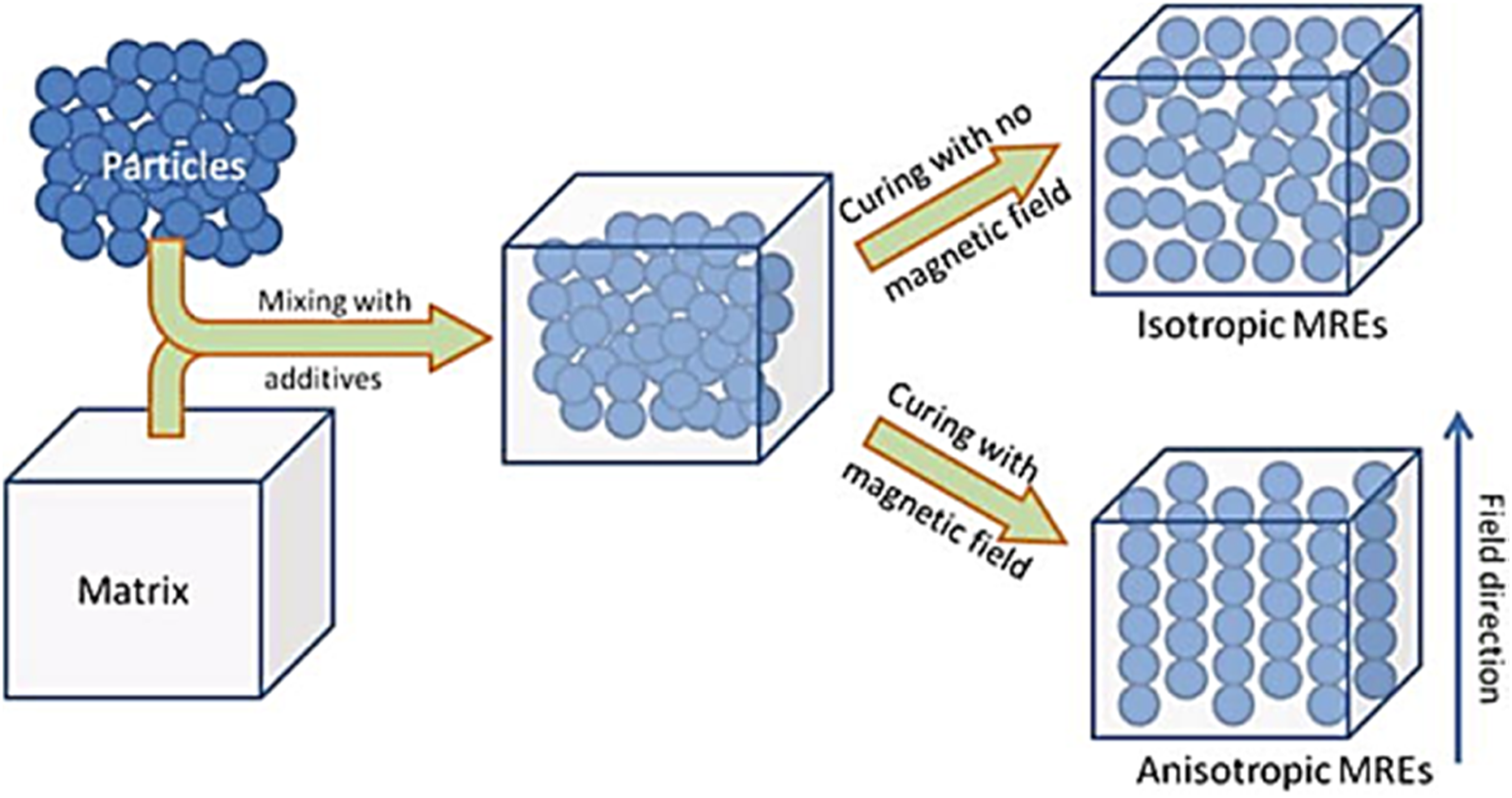
The internal magnetic particles that form like a chain in the direction of the magnetic field are the main factors in determining these elastomers' mechanical properties. 10 The better the particle arrangement is by controlling the magnetic field, the better the mechanical properties obtained from MRE. 11 There are lots of polymeric rubbers for the polymer elastic matrix such as natural rubber, silicone rubber and polydimethylsiloxane (PDMS).11–13 Also, the magnetic particles are mostly made up of carbonyl iron powder invented by BASF 15
Vibration phenomenon can be simply defined as repetitive motions or oscillations that happen when the structure is displaced from its origin or equilibrium position. Vibrations can be desired in some machining devices to serve functional purposes such as compactors, sieves and hoppers. In general, vibration is undesired in most cases as it is the cause of the noise, damage and many other inconveniences. Therefore, if such vibration is not controlled or isolated, it could lead to machinery breakdowns and structural failures. In vibration, the amplitude and frequency of any dynamic system are affected by two major aspects; the internal dynamics of the system and the external excitation force. Vibration isolation over a system is accomplished by one of the following elements, passive Different vibration isolation
16
: (a) passive, (b) semi-active and (c) active.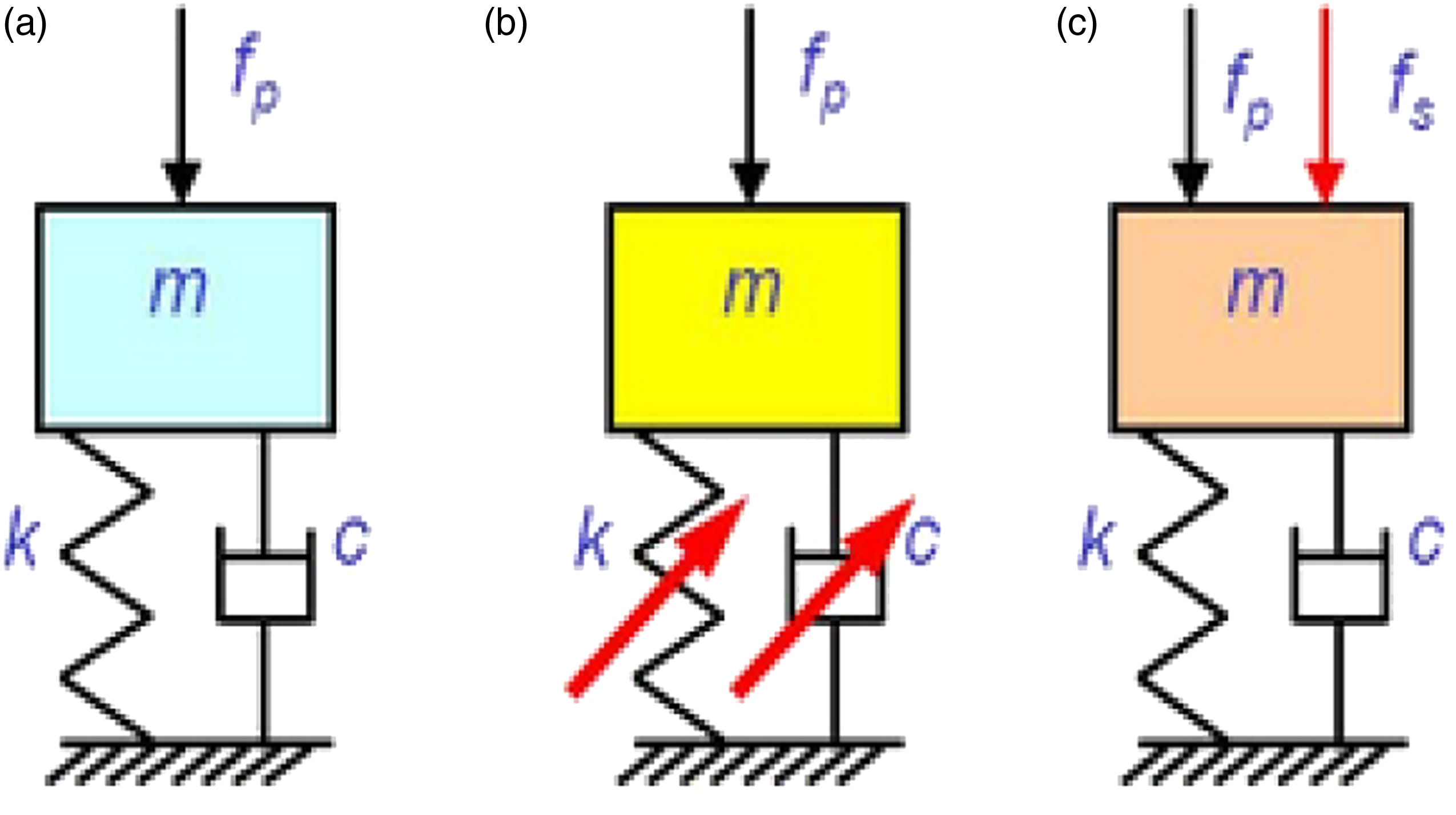
The passive vibration isolation system, as shown in Figure 2(a), consists of one or more devices attached or embedded in a structure. Passive vibration isolation is widely used in industry due to its simple design, low cost and ease of manufacturing. It can be designed for a system’s durability. If more or less stiffness is required, it can be as simple as changing the type of material being used or changing the size of the elements.
16
However, passive mounts can rarely attenuate all of the input vibrations in a system.
17
The active control system control actuators apply forces to the structure in a prescribed manner and have a significant external power source. The range of a force is wider and can achieve better performance, as in Figure 2(c). The secondary force
The main goal in vibration control is to eliminate and reduce the vibrations in mechanical systems, which means that vibration should be isolated from the systems. There are two types of isolation in each system, force isolation (transmissibility) and motion isolation (transmissibility) which can be either rotational or linear motion.
22
This is shown in Figure 3. Vibration forces can be directly transmitted to the system of interest from the input source. If the system is isolated using flexible and dissipative elements such as springs and dampers, the unwanted forces are filtered out. Vibration motions applied to moving parts of a mechanical system can also be absorbed through isolators.
23
Principles of vibration isolation systems
19
: (a) base motion isolation and (b) force isolation.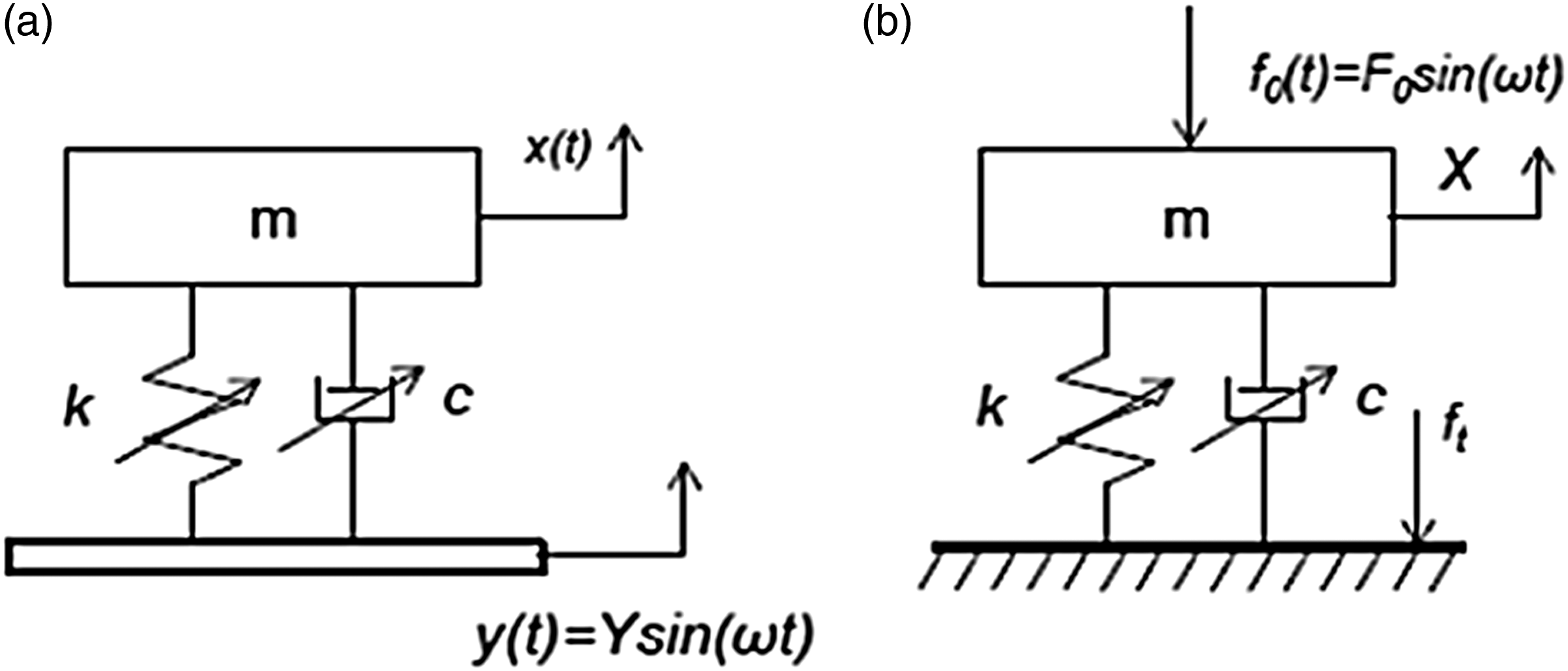
In this research, the semi-active vibration isolation utilizing MRE is proposed to be used on a drilling process prototype. The drilling process is used to serve in various tasks other than boring holes in the solid structures, such as spot facing, countersinking, tapping and reaming. The drill bit is a rotary cutting tool that is placed and pressed against the workpiece and rotates at very high revolutions per minute (RPM). This will force the drill bit to act as a cutting edge on the workpiece, which will cut off and remove the material (chips) from the hole as it is drilled.
In some applications, the drill string is long, such as boring holes in the earth’s crust to extract natural resources such as water, natural gas and minerals. Such long structures are prone to be subjected to massive and severe vibrations. Therefore, the complexity of the dynamic behaviour of drill strings is significant. Hence, this vibration needs to be controlled and isolated to avoid machine damage or failure. During the drilling process and due to cutting forces, the drill string is subjected to three main modes of vibrations: longitudinal, torsional and lateral as shown in Figure 4. The overall performance of the drill string is affected by these modes of vibration. Modes of vibration during the drilling process.
24
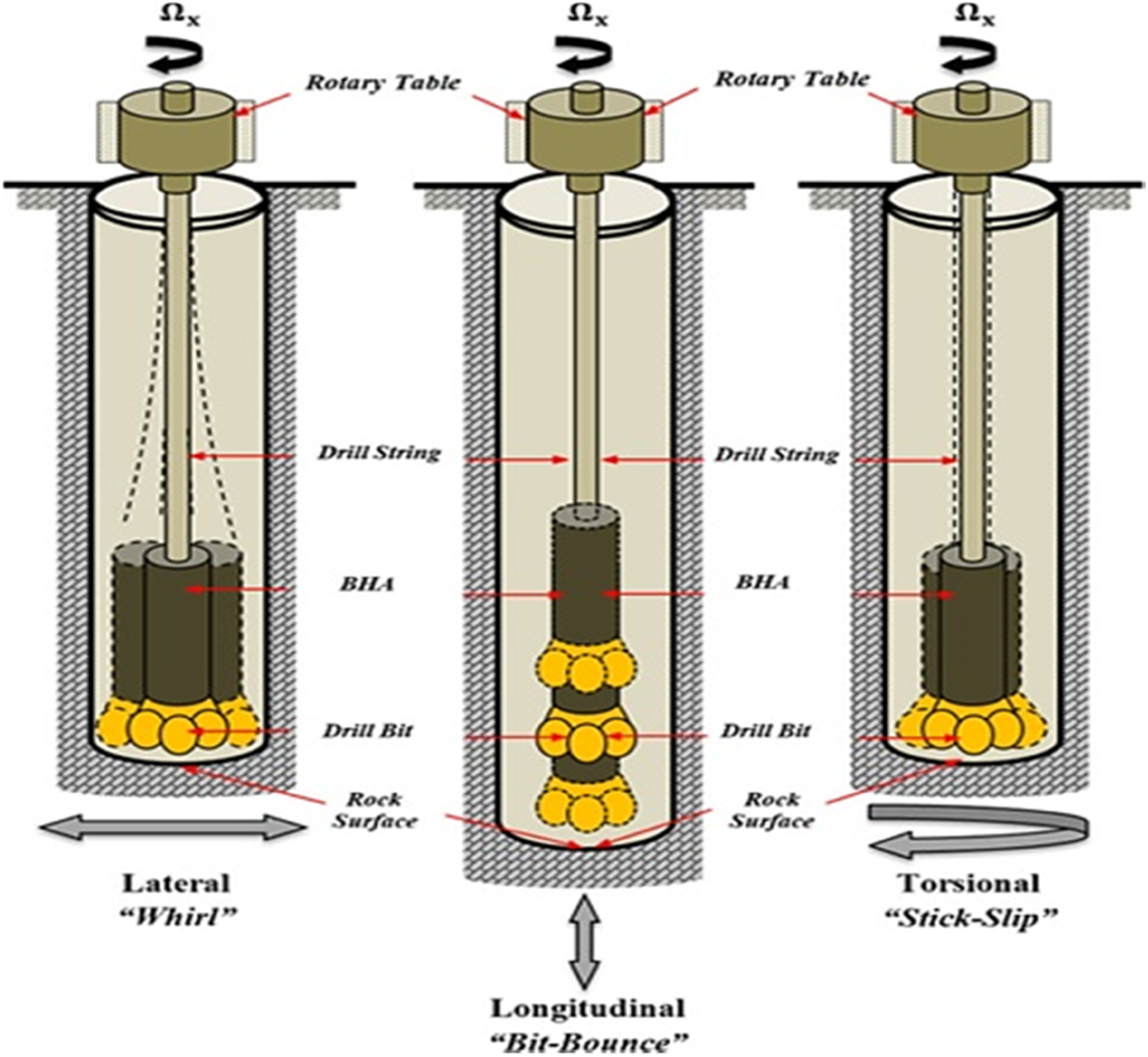
Each of the three modes of vibration can be risky and has a destructive nature. In longitudinal mode, the vibration motion is parallel to its axis. ‘Bit-Bounce’ is the phenomena that cause this mode; this creates instability during drilling, affecting the contact of the drill bit with the workpiece. This can cause damage to the drill bit cutting structures such as seals and bearings. 25 Secondly, the torsional mode is associated with phenomena called “stick-slip” which causes irregularities during rotation. This can cause severe damages such as bit wear, fatigue and shock loading and lead to equipment failure. Lastly, the lateral mode of vibration is side-to-side motion which causes bending in the drill string. The eccentric rotation of the drill string around an axis other than its geometrical centre is called ‘whirl’. This vibration mode is very severe, leading to the failure of the drill string due to excessive stresses. However, since the drilling process usually makes holes, it requires the drill bit to rotate and a longitudinal load to force the drill bit to penetrate the workpiece, which excite torsional vibration. This study focuses on the torsional vibration mode isolation. A test rig representing a drilling process is designed and developed to study and implement vibration isolation.
MRE isolator is used in various applications such as for protecting buildings from disastrous vibration due to earthquake. A semi-active MRE base isolation system for the different benchmark was developed by Gu et al. 26 It was produced with the inverse model of the general regression neural network (GRNN). It was concluded that it could speed up the calculation time and training methodology. The work of Almeida et al. 27 used MRE to suppress flexural wave on a beam solely on a simulation basis. The amount of damping depends on the thickness of the MRE layer, and increasing thickness also results in small or negligible damping. Design of a working MRE prototype based variable stiffness and damping isolator (VSDI) and real time tested on a 1:16 scaled three-storey building using Lyapunov-based control strategy. The controlled states found to reduce the maximum acceleration and displacement of the building more than the passive state. Some analytical models of MRE have been studied by Syam and Muthalif 28 to observe their hysteresis behaviour and plot the transmissibility curve versus frequency. Field-dependent rheological properties of MREs are investigated via rheometer to analyse the change in dynamic modulus of MREs such as storage modulus, loss factor and absolute MR effect. These experimental results indicate that MRE samples with a higher corrosion rate of CIP exhibit lower storage modulus, loss factor and MR effect, which would subsequently deteriorate the performance of MRE. 29
A prototype of MRE using the variable stiffness and damping isolator (VSDI) model applied on a (1:16) scaled three-storey building developed and designed. 30 This analysis was done using the Lyapunoy-based control method. Results showed that the maximum acceleration and displacement is reduced using MRE more than using a passive vibration isolation strategy. MRE is used in the vibration isolation of a small-scale wind turbine aluminium blade SH3055 (Bergey Wind Power Co. Inc., USA). For the turbine blade with a controller on, the gain reduction for 1st mode was 15.83 dB, and 2nd mode was 13.07 dB. 31 The introduction of a variable stiffness coupling (VSC) fitted within a shaft for torsional vibration isolation that would adapt and change its attenuation frequency range is presented by Syam et al. 32 The VSC concept on torsional vibration isolation is tested experimentally. MRE samples with 40% volume fraction are fabricated and manufactured using a 3D mold design and fixed within a coupling in a shaft to investigate the magnetic field effect on the torsional rigidity. Impact hammer test is conducted along with an accelerometer to obtain the transmissibility factor analysis. Results show that the vibration level decreases when the magnetic field increases. The 1st natural frequency of the system happened at 26 Hz and moved to 28 Hz when the applied current increases from 0 mT to 12.38 mT. MRE torsional stiffness increased from 37.4 N.m/rad to 61.6 N.m/rad when the current increased from 0 mT to 12.38 mT.
A tuneable automotive bushing for vibration isolation on translational and rotational wheels motion using MR was designed by Ginder et al.
33
Steel is used to make the two concentric hollow cylinders (bushing). Deformation testing was conducted using the sinusoidal signal at 2 Hz, results showed that an increase of 25% of the stiffness and damping is obtained in both axial and radial directions. This increase is related to an applied current up to 5A. Liao et al.
34
achieved a tuneable stiffness and damping using four layers of MRE and three coils for magnetic field generation. A novel MRE isolator to control vibration in vehicles, stiffness and damping are increased with magnetic field in both compression and shear modes were proposed by Behrooz et al.
35
and Alias et al.
36
Behrooz et al.
35
used MRE for base isolation of a civil structure, four MRE samples were trapezoidal in geometry with 12 mm thick are used in the system. Four coils with 800 turns are used in top and bottom to produce a magnetic field. Force-displacement response was plotted, and a 57% increase within the loops is found for different applied current. Marzuki et al.
37
used MRE as a semi-active vibration isolator to suppress the torsional mode of vibration. The volume fraction of the iron particles is 40% within the elastomer. The setup consisted of a power supply, an amplifier, a dynamic signal analyser (DSA), an inertial shaker, an accelerometer and a solenoid for magnetic field generation. The frequency range was 0 Hz–400 Hz, and the applied current was up to 6A. Results showed that a shift of 3.9 Hz of the natural frequency achieved. Besides, the damping ratio of the system was slightly decreased with the magnetic field. Hashi et al.
37
developed the mathematical and experimental setup for dynamic tuning of torsional vibration; it is found that the stiffness of MRE increases with the magnetic field. Also, the transmissibility curve (
Since the application that is investigated in this research is drilling, it is worth collecting and reporting articles that discussed vibration isolation in a drilling process. Using MRE, Kumbhar and Gawade 39 have experimented with controlling lateral vibrations of drill on the centre lathe, results showed that 22% of lateral vibrations are absorbed under magnetic field. This study is limited because only time domain was investigated. FEM was used for the analysis of vibration in a drill string, 39 this work determined the natural vibration modes and forced harmonic response for drill string so that resonance is avoided. Results showed the range of frequencies that can be excited to avoid maximum stress and amplitude. Alsaffar et al. 40 presented methodology to isolate vibration in drill strings by proposing a type of periodic drill strings with passive periodic inputs, it was concluded that this type of drill strings could operate on a broader range of frequencies than conventional drill strings. It included both FEA and an experimental verification and results showed agreement. Majeed et al. 41 have shown a drill bit mitigation analysis to isolate lateral vibrations. It was concluded that using the physical solutions is the only way to overcome drill bit whirl effect. Rajnauth and Jagai 42 have investigated some solutions to avoid torsional vibrations using a real-time display of the magnitude of vibration in the torsional mode. This work was concerned on observing the results of reducing these vibrations, results concluded that the drilling bit life time and drilling rate are enhanced, a reduction in fishing time and minimizing failures of drill string/Bottom Hole Assembly (BHA) failures.
Enormous developments are happening in various sectors worldwide such as oil and gas, industrial, buildings, power, rail transport and infrastructure. These projects require sophisticated technologies. Oil and gas is the main source of energy and economy in the GCC countries. The extraction of natural gas from underground requires very advanced drilling machines and operations onshore and offshore. Therefore, there is a massive need to perform research in vibration isolation for such a process. This paper contributes to utilizing MRE as a semi-active vibration isolator to reduce the drilling system’s torsional vibration. By studying such material on a drilling test rig, this can lead to a significant enhancement in such technology such as a better lifetime of machines that can improve the energy sector’s economy by improving the efficiency of machines.
This paper is outlined as follows: the Introduction section introduces the research overview as it reviews MRE, vibration isolation and vibration in the drilling process, reviews MRE properties and characteristics, and its applications in vibration isolation. It also reviews different strategies used in vibration isolation during the drilling process since it is the proposed application where MRE is used in this research. The Analytical Model for the Prototype Drilling System section shows the derivation of the mathematical model of the proposed drilling system. The Experimental Developments and Prototype Setup to Test MRE section includes the fabrication of MRE samples, and a 3D CAD drawing of a drilling system is presented and shows the methodology followed for the two tests. It also presents the experimental setup development. The Experimental Results and Discussion section presents the experimental results and discussion. Finally, this paper ends with conclusions of the main findings, which are presented in the Conclusion section.
Analytical model for the prototype drilling system
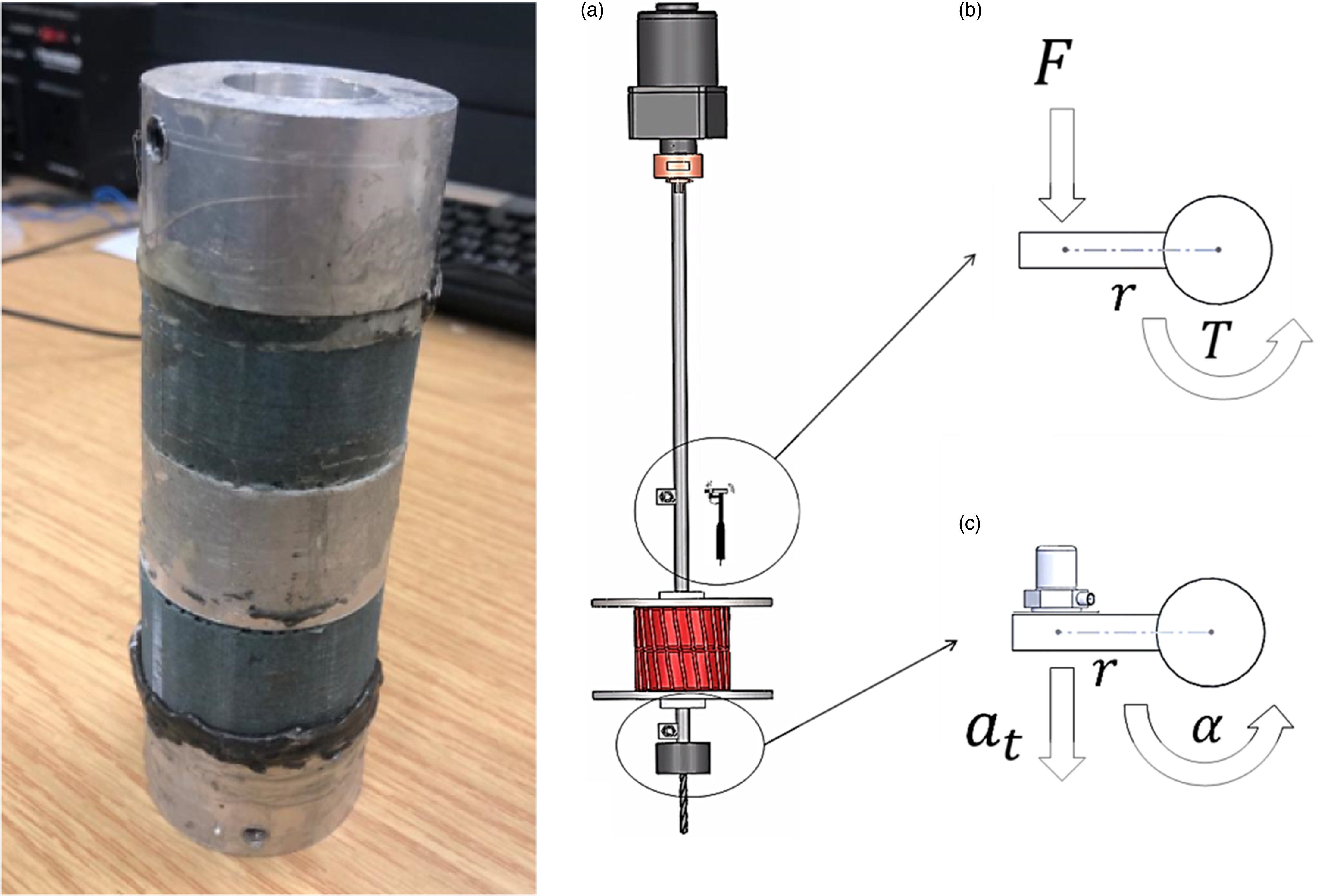
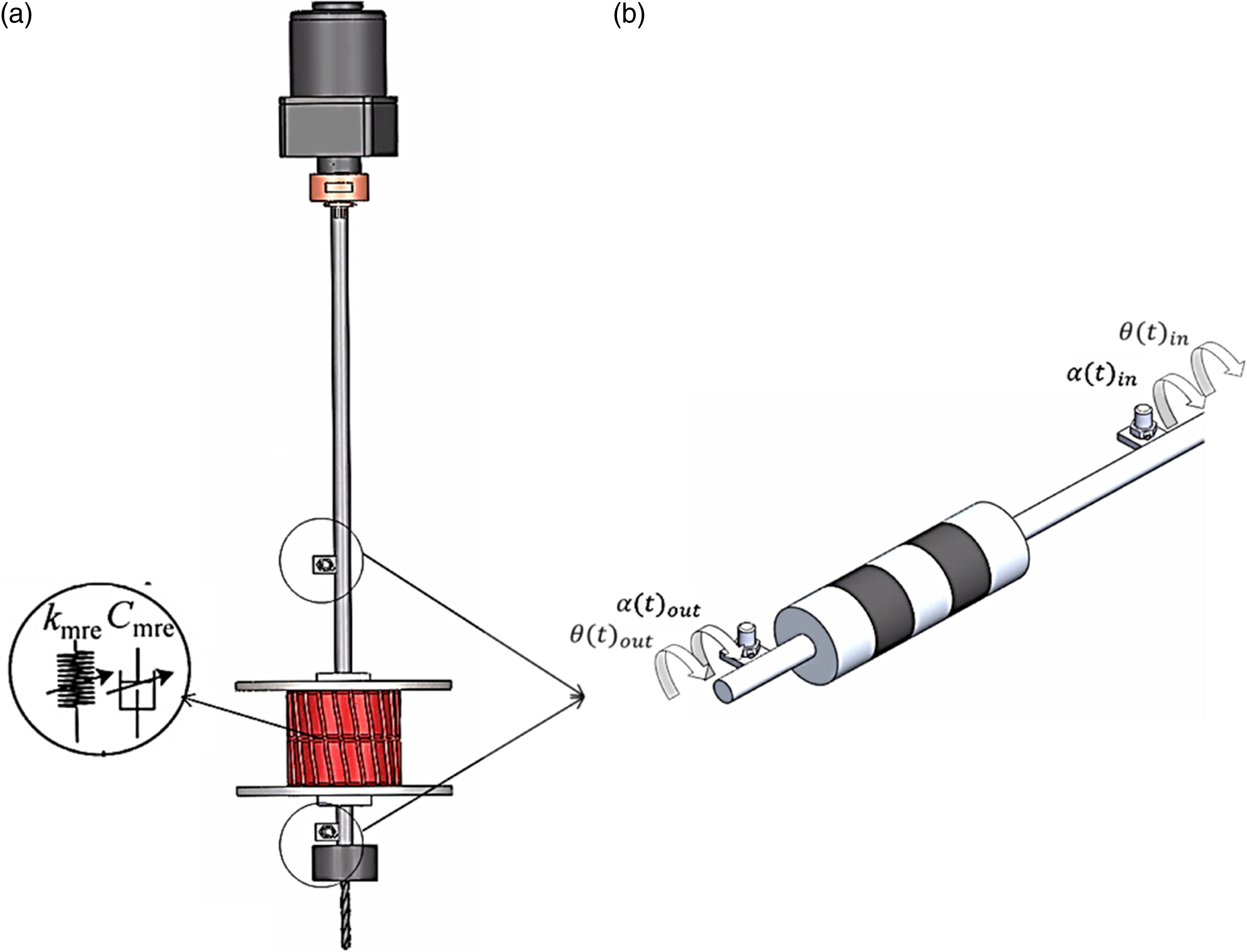
The 3D isometric view of the system used in this study is shown in Figure 5(a). The system is vertically oriented as a representation of a drilling process. The system consists of a motor to drive torque to the shaft (drill string). Two accelerometers are fitted on two plates (upper and lower) attached to the shaft. A slip ring is used to transmit the accelerometers readings while in rotation. A flexible coupling contains the MRE. It used to transmit the torque between the two shafts, that is, before and after the MRE. The electromagnetic coil which surrounds the MRE produces the magnetic field. Finally, the disc attaches the drill bit at the bottom of the drill string. The shaft is 25 mm in diameter and 600 mm in length. The whole length of the system does not exceed 1 m. This short length of the shaft is not to create bending or wobbling during rotation and to try as much as possible to keep the system aligned during rotation. The transmissibility of the whole system will be a combination of three different rotations in terms of (a) 3D CAD drawing of the proposed drilling system and (b) Schematic mathematical model derivation.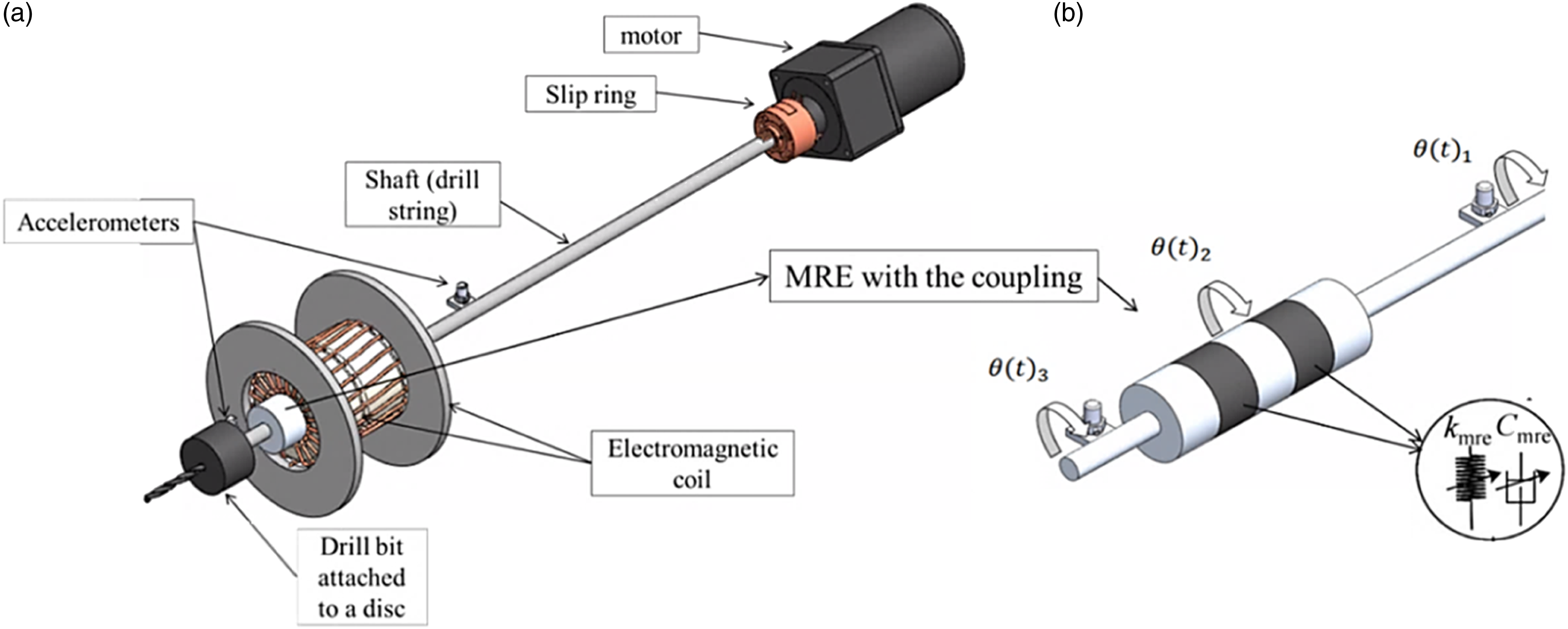
The derivation of the mathematical model of this system starts with the displacement transmissibility definition. In mechanical vibration, the concept of displacement transmissibility is very significant. It is the magnitude of the ratio of how much oscillation is being transmitted to a point from the excitation input of the source. Since the torsional vibration is to be isolated, the angular displacement transmissibility is presented, which the ratio of the angular displacement (rotation) transmitted to the excitation torque. In general, the angular displacement transmissibility can be presented as follows

As shown in Figure 5(b), the two MR elastomers are separated by an aluminium cylinder as a part of the coupling. Therefore, three angular displacements are presented; the input angular displacement from the motor to the shaft before the MRE coupling

Therefore, the simplified schematic of the mathematical model based on the angular transmissibility analysis can be seen from Figure 5(b) by


The transfer function of this system can be obtained by applying the Laplace transform to differential equation (5). Applying of

By taking the common factors

The transfer function can be obtained by

The angular displacement transmissibility factor equation can be obtained firstly by converting equation (8) from the (s-domain) to the frequency domain (

The angular displacement (torsional) transmissibility factor can be obtained by taking the magnitude of equation (9)

Experimental developments and prototype setup to test MRE
MRE Fabrication
Properties of materials for magnetorheological elastomer fabrication.
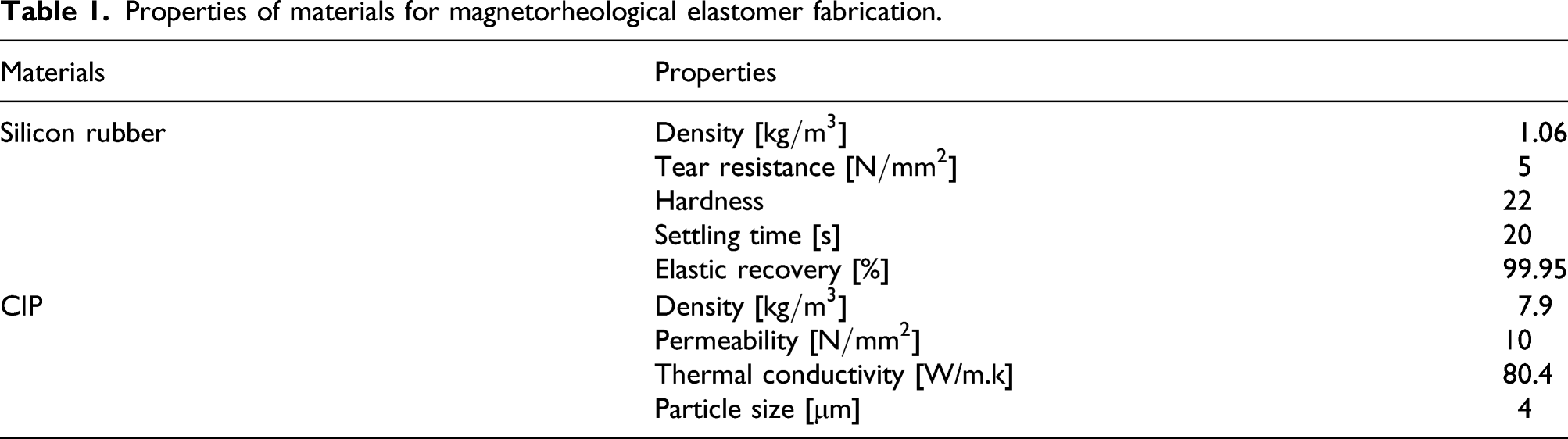
Before curing the silicon rubber (base + catalyst), CIP is mixed with the base at a 35% mass fraction MF. Two cylindrical specimens were manufactured and the fabrication of each sample used 50 g of silicon rubber (base + catalyst). The MF fraction required for the CIP to the silicon rubber is 35%. Therefore, the amount needed of CIP can be obtained from the following equation
This shows that the required amount of CIP is 26.9 g. Knowing that the density of the silicon rubber is 1.06 kg/m3 and density for CIP is 7.9 kg/m3. The volume fraction (VF) can be determined by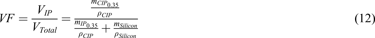
By applying equation (12), the VF is 6.73% of the CIP of the total composite. This is the volume fraction between the silicon rubber and CIP needed for that specific amount of the composite to achieve a mass fraction (MF) 35% CIP to silicon rubber ratio. The fabrication of the mold to cure and cast the MRE is 3D printed using ABS material. The 3D model of this mold is shown in Figure 7(a). This unique design of the mold consists of three main parts: lower and upper covers and the middle part. The lower cover was attached to the middle part using four screws; one at each corner. Then, the mixed silicone fluid with the CIP is poured from the upper part and then the top cover was attached to the middle part to keep the MR elastomer inside. The extruded part was made to achieve the required design of the MRE that fits the coupling.
The flexible coupling that will contain the MRE is consisting of three aluminium cylinders. The aluminium cylinders are 50 mm in diameter and 30 mm in height. These cylinders are extruded for the MRE to fit inside them. The extruded part follows a cylindrical shape with a diameter of 15 mm and a height of 5 mm. The MRE dimensions are also similar to the aluminium cylinders, with a diameter of 50 mm and a height of 30 mm. On both faces of the MRE, a cylindrical hole is made to fit the aluminium cylinders. Figure 6 shows the MRE fitted with coupling with its dimensions. This design is used for the drilling prototype. MRE and the coupling 3D design with dimensions.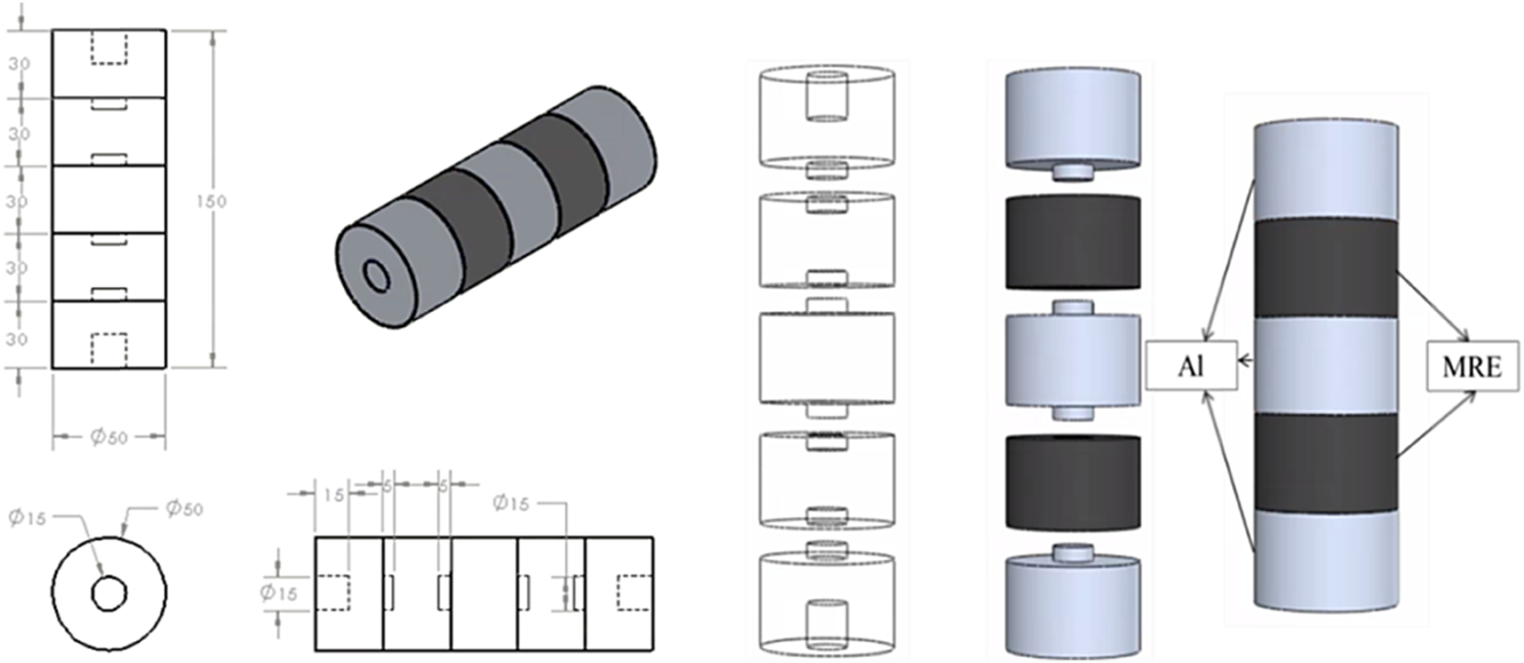
The fabrication procedure taken to achieve the desired coupling with MRE fitted in it started with modelling and printing (3D) the mold case as in Figure 7. MRE is fabricated using a measuring cup and a digital balance to measure the amount needed for silicon rubber and CIP. Firstly, the silicon rubber base is poured into the measuring cup (Figure 8(a)). Secondly, the CIP is added, followed by the silicon rubber catalyst (Figure 8(b,c)). (a) The 3D drawing of the mold case and (b) 3D printed mold case. Mixing MRE components.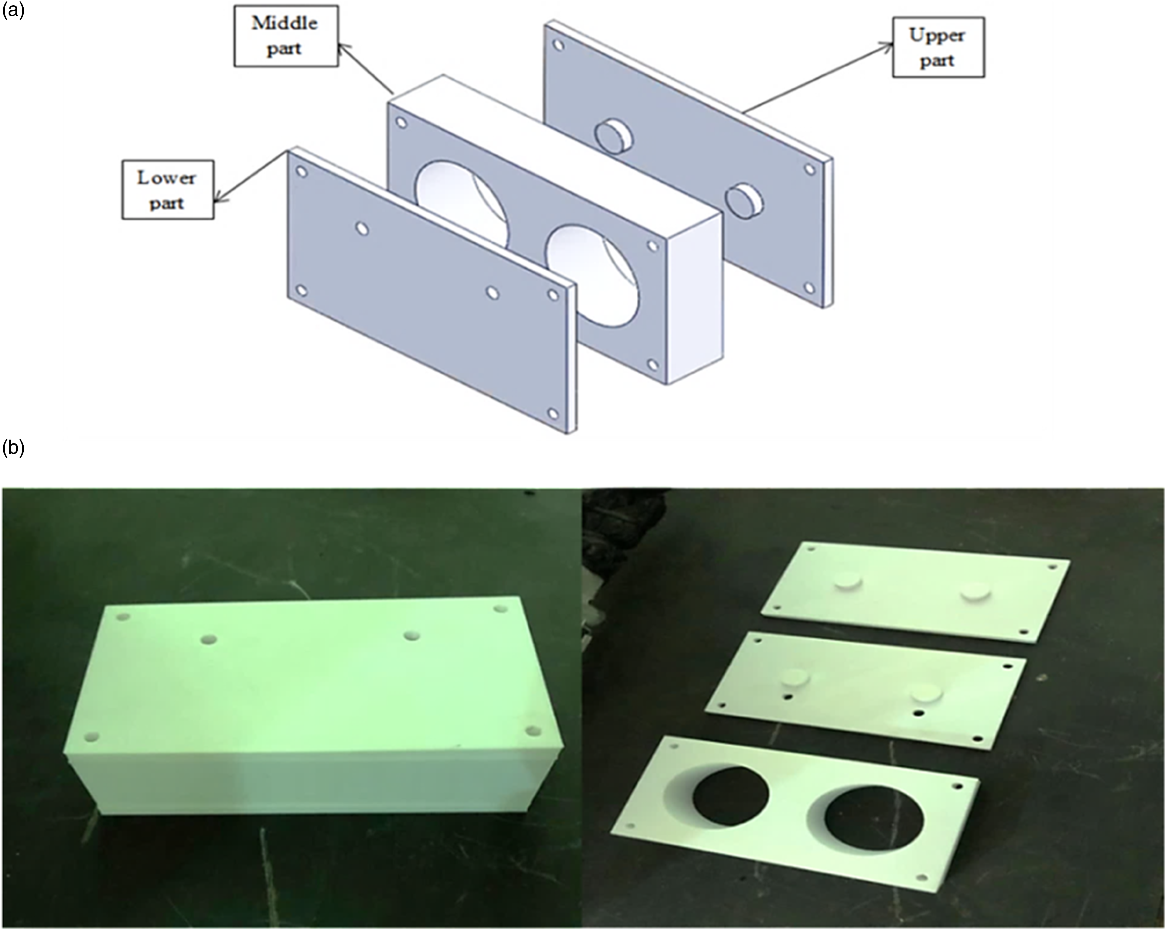
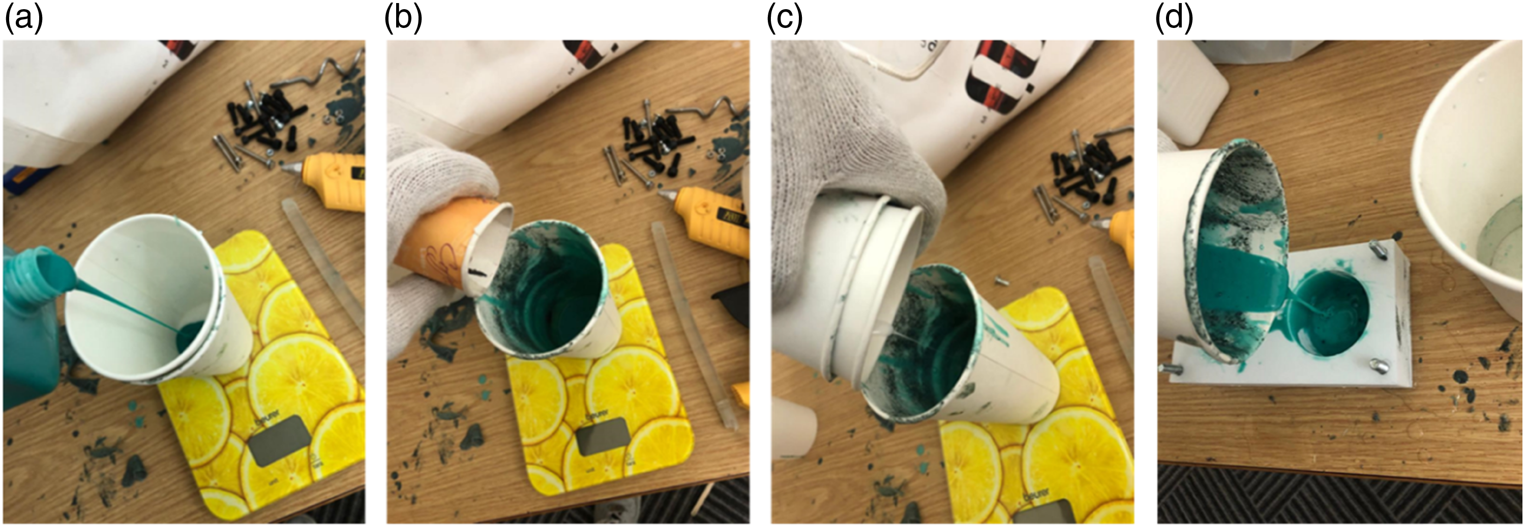
After that, a proper mixing using a mixer is done to guarantee that the CIP is mixed through the whole composition of the elastomer, the mixing was done thoroughly so that the CIP sedimentation at the bottom does not occur. Finally, the MRE is poured as a fluid into the mold and was covered for 20 minutes for curing (Figure 8(d)). After the curing, the MRE samples are ready to be extracted from the mold. After getting the MRE prepared as in Figure 9, the MRE is fitted into the three aluminium cylinders using the extrusions made in their design and by a strong epoxy between them as in Figure 10. MRE sample after curing. Flexible coupling with MRE. The methodology of the impact hammers test: (a) impact and response locations, (b) input excitation representation and (c) output response representation.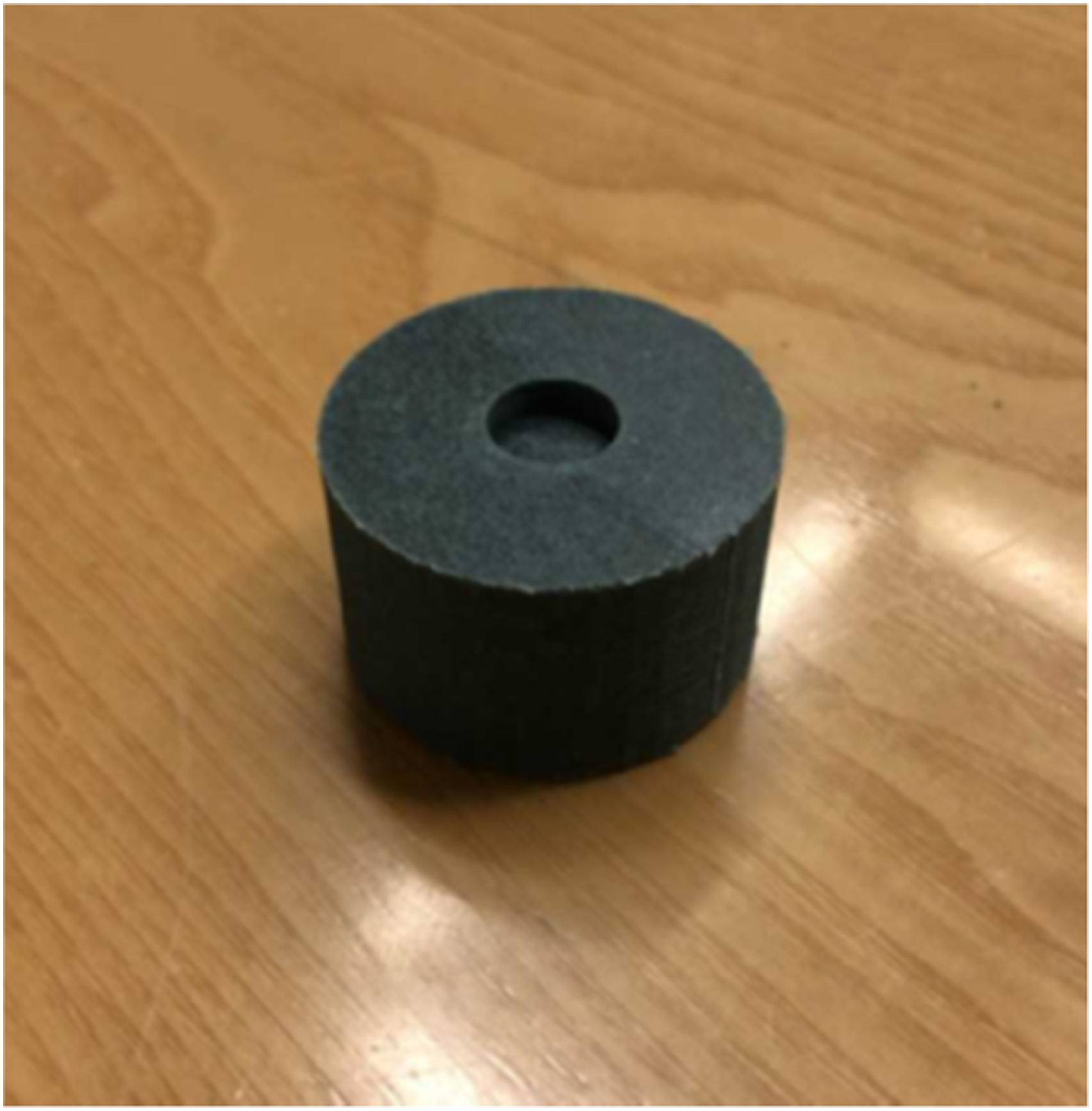
Experimental setup and Methodology
A prototype test rig was developed to perform two different tests, the impact hammer test and continuous rotation test. The methodology of these experiments can be divided into two parts. Part 1 – Impact hammer test to obtain the angular displacement transmissibility. In this test, excitation is given before MRE coupler, and the response is obtained after the coupler as a Frequency Response Function (FRF). Part 2 – dynamic test will investigate the angular displacement transmissibility during continuous rotation of the shaft (drill string).
Impact hammer test methodology
The impact was given on the upper plate as shown in Figure 10(b), and the response is obtained using the accelerometer fitted on the lower plate as in Figure 10(c). This test is done to get the transmitted load of the shaft before and after the presence of MRE. The response needed in this test is the FRF which represents the transfer function of the system. The transfer function is the ratio between the output response and the input excitation. The response obtained from this test is the frequency response in terms of the ratio of the excitation force (F) to the output acceleration (
The FRF needed in this experiment must be in an angular domain because the application is to obtain the angular transmissibility factor. The FRF obtained from the data acquisition system is as follows


By substituting equations 13 and 14 into equation (15)
The output angular acceleration to input torque; torsional transfer function 
From the FRF, half bandwidth theory is applied to obtain the damping ratio and the torsional stiffness of the MRE as the magnetic field increases. The damping ratio 


The schematic representation of the methodology and experimental setup for this test is shown in Figure 11. This test is done while the system is static. The hammer’s impact is given on the upper plate to get the response on the lower accelerometer. The data acquisition system (DAQ) receives an input signal from the impact hammer and acceleration output. It uses the fast Fourier transform to convert the data from the time domain into a frequency domain (FRF). Equation (17) is used to obtain torsional transfer function (TTF), that is, output angular acceleration to the input torque. The DC regulated power supply is used to supply current to the electromagnetic coil, which controls the magnetic field. The coil surrounds the MRE and gives a magnetic field to change its property. The current values range from 0A to 3A. The slip ring is used to deliver the response signal of the lower accelerometer to the DAQ. The Gauss/Tesla meter is used to measure the magnetic field produced inside the coil when the current supplied is varied. The disc that attaches the drill bit is used to give a moment of inertia during the test. Schematic representation of experimental setup for the impact hammers test to obtain torsional transfer function (TTF).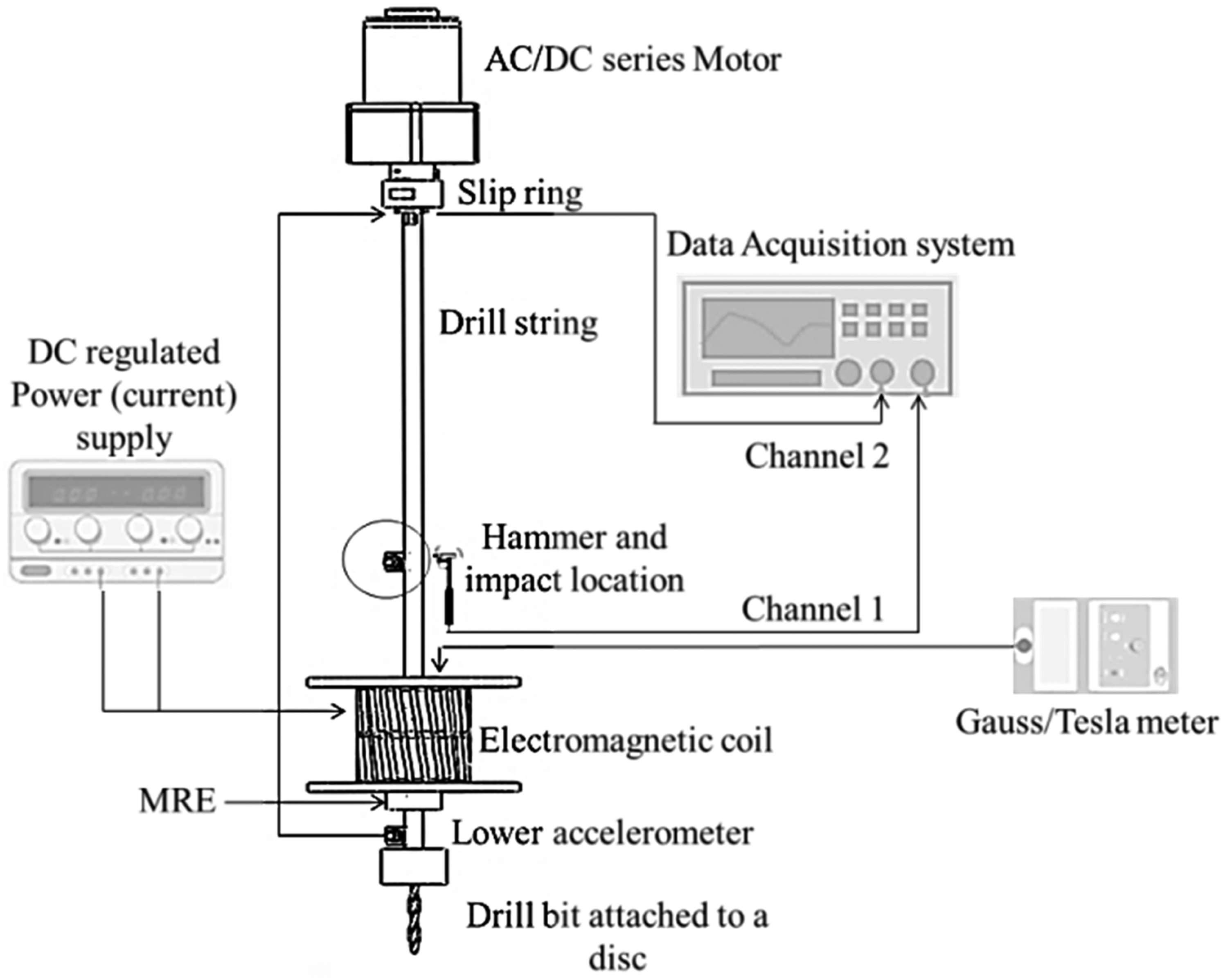
Continuous rotation test methodology
In this test, the transmissibility factor TT is obtained during the continuous rotation at a certain speed (revolutions per minute). Two accelerometers are attached before and after the MRE, as shown in Figure 12. These readings can be integrated twice to get the angular displacement; however, the transmissibility factor is a ratio, no need for the conversion. The relationship between tangential acceleration and angular acceleration was given as in equation (14). Both shafts (drill string) have the same radius Continuous rotation test methodology, (a) input and output locations and (b) output and input angular acceleration/displacement.

In summary, this test investigates the angular displacement transmissibility of the system under continuous rotation. The motor drives the shaft (drill string) at a constant speed (RPM) using the external power supply (voltage) ranges from 5 V to 7 V with an increment of 0.25 V. The motor starts to rotate at 5V. This is due to the load of the system. The speed (rotation) of the shaft (drill string) is measured using a tachometer (in RPM) and then converted to frequency (Hz). This conversion was done using Schematic representation of experimental setup for the continuous rotation test.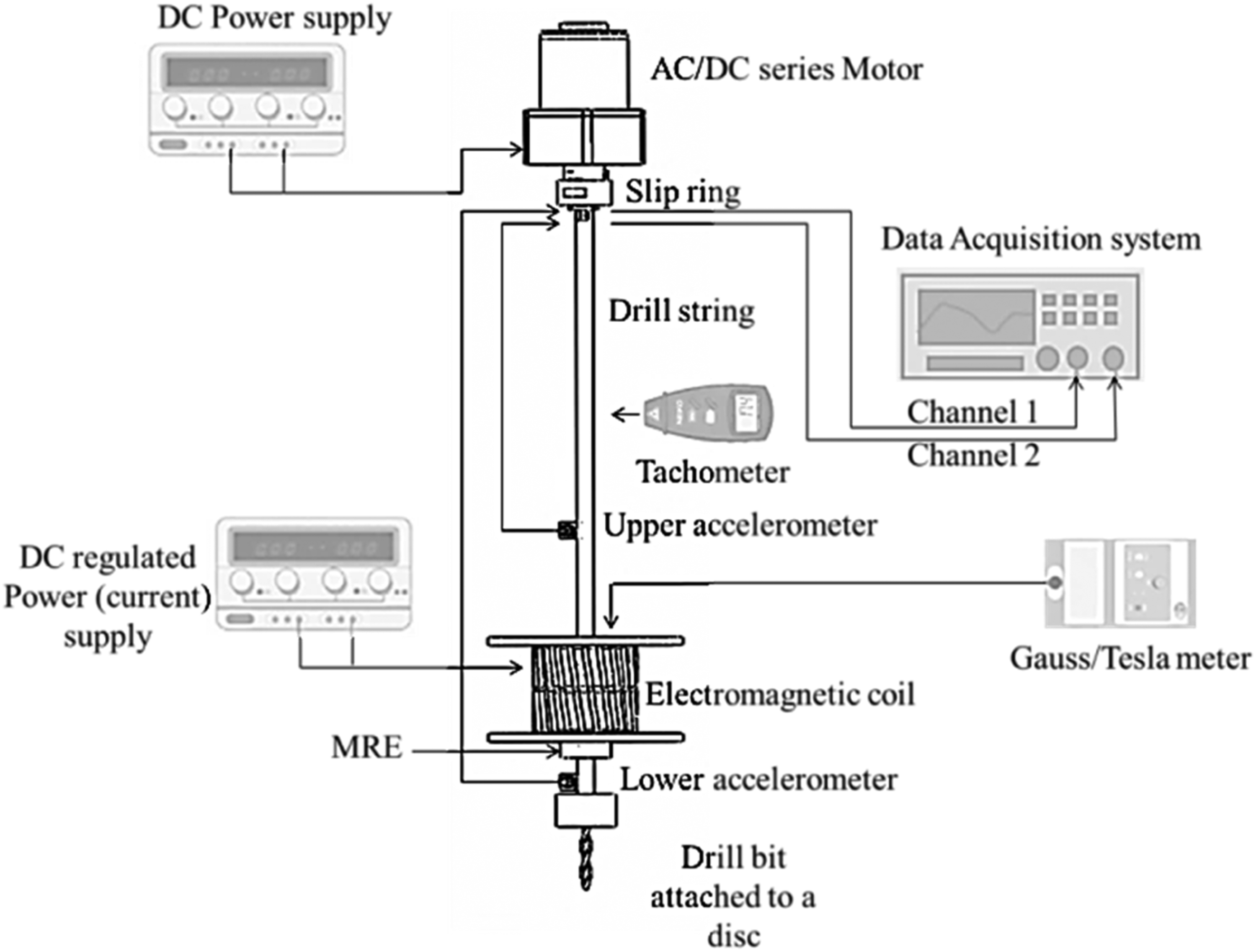
Experimental Setup and Developments
This section will further explain the methodology used in both tests by representing the experimental setup and all other related developments. Figure 14 shows the complete experimental setup used for both the impact hammer and continuous rotation test. The experimental setup for the impact hammer test consists of an aluminium shaft representing the drill string. An ICP type accelerometer sensor which a sensitivity of 101.2 mv/g which includes a built-in amplifier is fitted after the MRE as in (10) in Figure 14. It is connected to the DAQ (CF-H2 TOUGHBOOK) as an input channel 2. The hammer (PCB) is used to give an excitation signal to the upper plate. The top plate fitted the upper accelerometer for the second test. The hammer is connected to the DAQ as an input channel 1. The slip ring (MT01218-0612) is used to deliver the response of the lower accelerometer to the DAQ. The MRE is fitted with its coupling to act as a vibration isolator in the system surrounded by the electromagnetic coil with a power supply to provide current to produce a magnetic field. Experimental setup for both tests. (1) Tachometer, (2) power supply unit, (3) AC-DC series motor, (4) slip ring, (5) shaft (drill string), (6) electromagnetic coil, (7) upper accelerometer, (8) hammer, (9) MRE, (10) lower accelerometer, (11) DC regulated power supply, (12) digital multimeter (DMM), (13) gauss/Tesla meter, (14) DAQ.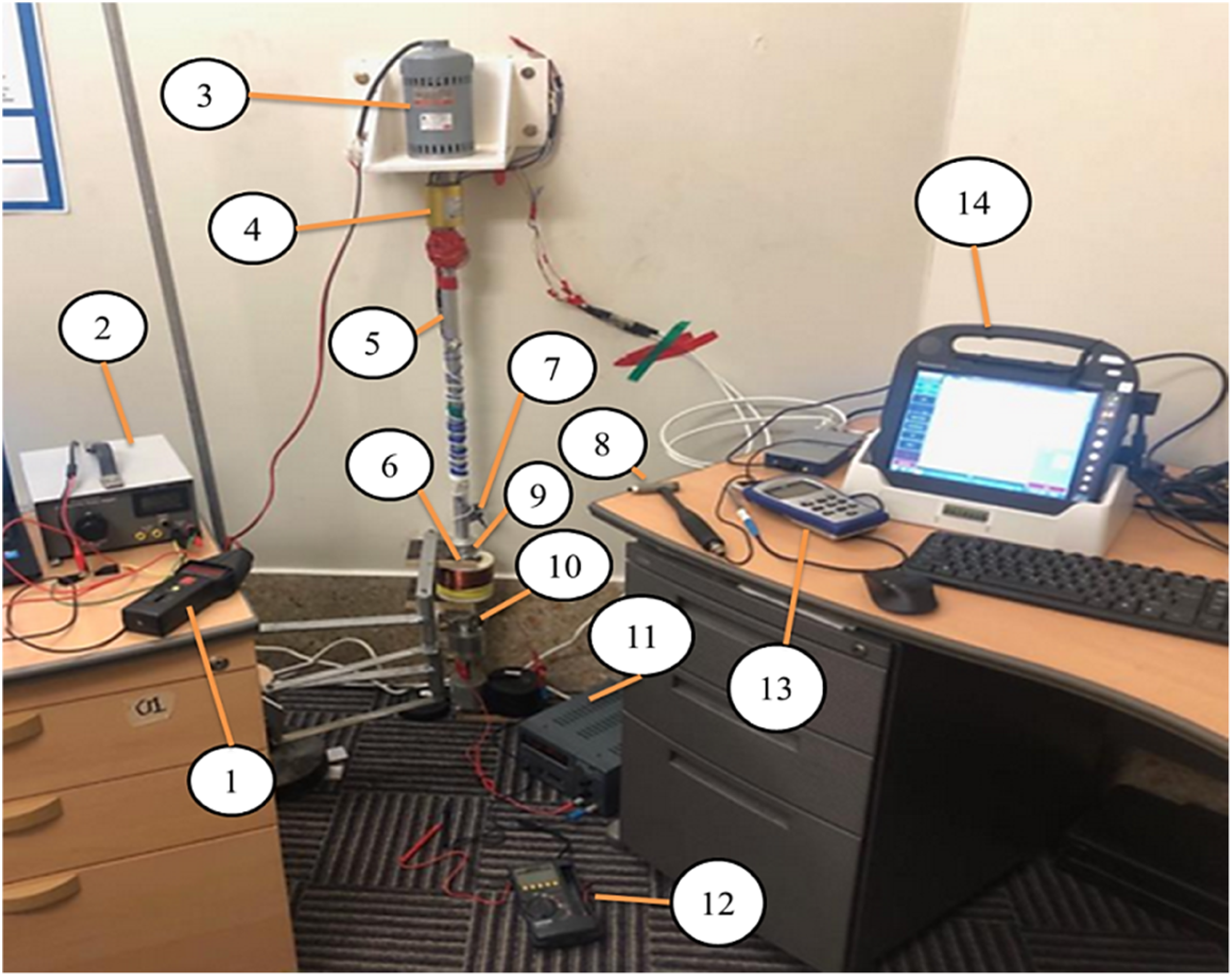
The experimental setup for the continuous rotation test consisted of an aluminium shaft (drill string). An AC-DC series motor (2M191 A) is used to drive the shaft. A power supply unit is used to control motor speed. The slip ring also delivers the signals of the upper and lower accelerometers while rotation to the DAQ as input channels 1 and 2, respectively. The two accelerometers are ICP types with a sensitivity of 101.2 mv/g. The tachometer (CT6) is used to measure the rotation of the shaft at a specific voltage input to the motor.
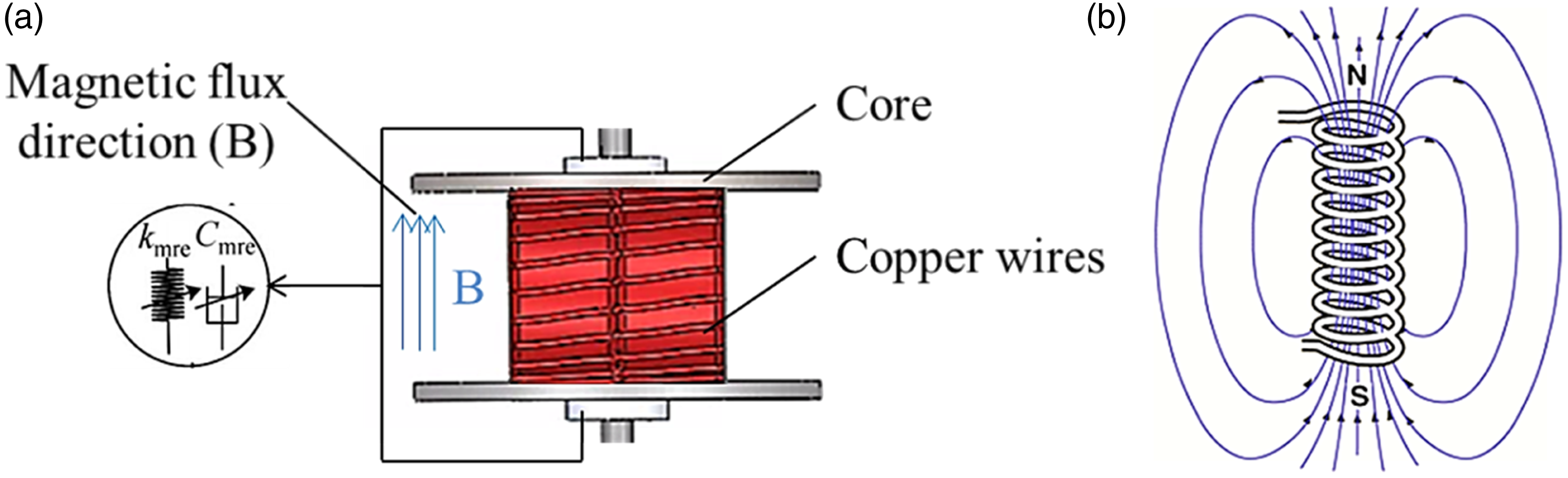
The electromagnetic coil consists of an ABS material core which was 3D printed and copper wire which was wrapped using winding with 1250 turns. FW Bell Gauss/Tesla meter is used to measure the core’s magnetic field, which has the MRE in between. Insulating materials are used in order not to absorb any magnetic flux produced from the coil and to ensure that the flux is focused on the MRE. The digital multimeter is used to measure the current passed through the coil. Figure 15(a) shows the electromagnetic coil design and the magnetic flux lines (B), with MRE is placed at the centre of the core. Figure 15(b) shows the theory behind using a coil as a magnetic field generator in interior volume. The magnetic flux density lines move uniformly from the South to the North Pole, ensuring that the volume is sufficiently exposed to a magnetic field. (a) Electromagnetic coil design and (b) magnetic flux density direction through a coil.
49
.
In shear mode, the direction of the external load (Force or torque) is perpendicular to the direction of the external magnetic field B, and the direction of the external magnetic field B is parallel to the forming chain’s direction of the MRE ferromagnetic particles.
47
The magnetic flux density is recognized as
48

Experimental results and discussion
A simple experiment is conducted to measure the magnetic field produced by the electromagnetic coil used to create a magnetic field to the MRE. The current (0A–3A) was supplied to the coil, and the magnetic field generated inside the core is recorded in G and mT and plotted in the data table in Figure 16. It can be seen that as the current increases, the magnetic field within the coil increases as well. Measurement of the magnetic field during the experiment is essential to ensure that the MRE is being influenced by magnetic flux intensity. The magnetic field generated versus applied current.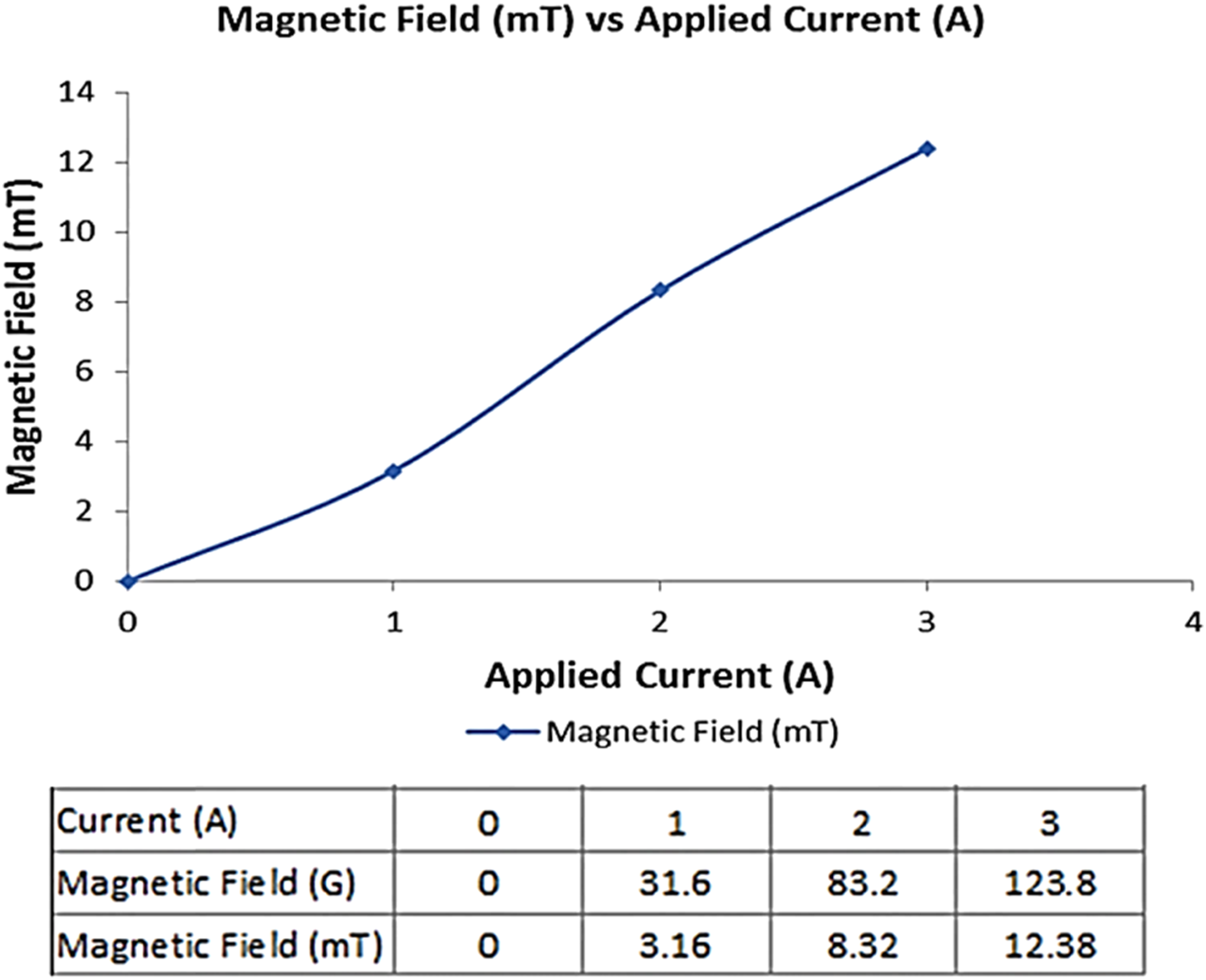
Impact hammer test results
Results of the impact test give TTF for a range of frequencies. The impact hammer test was averaged over three tests for each value of the magnetic field; investigate the effect of the magnetic field variation on the torsional stiffness and damping properties. The TTF plot was extracted from the DAQ results that were processed as in equations 14–17. The torsional TTF, which includes the excitation torque input and the angular acceleration response for different current values, is presented in Figure 17. The system starts to vibrate at its maximum in the low-frequency range (0 Hz–50 Hz); this indicates that the resonance frequency occurs at this range. Above 50 Hz, many amplitudes and patterns appear as there is a fluctuation. The focus of this research will be given to the low-frequency ranges. This range agrees with the fact that vibration problems in most rotary machines occur at low excitation frequencies, this leads to large amplitudes of vibration during resonance.
50
Figure 18 is a zoomed-out view of low frequencies ranges 0–50 Hz. TTF versus frequency. TTF versus frequency (0 Hz–50 Hz).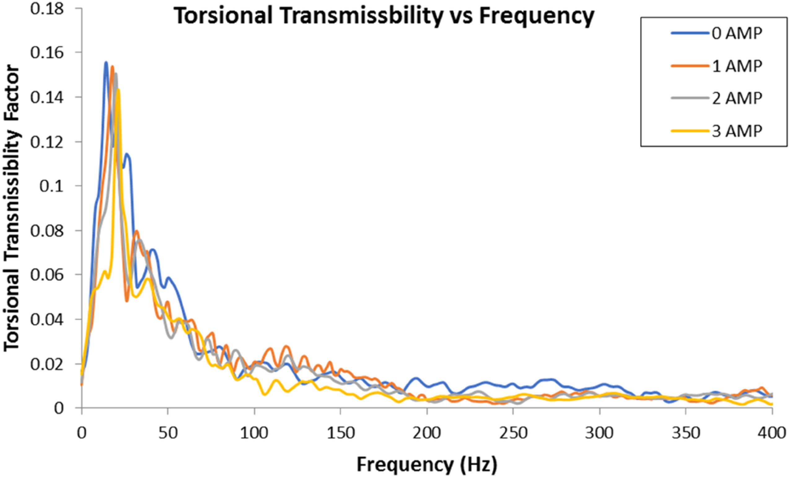
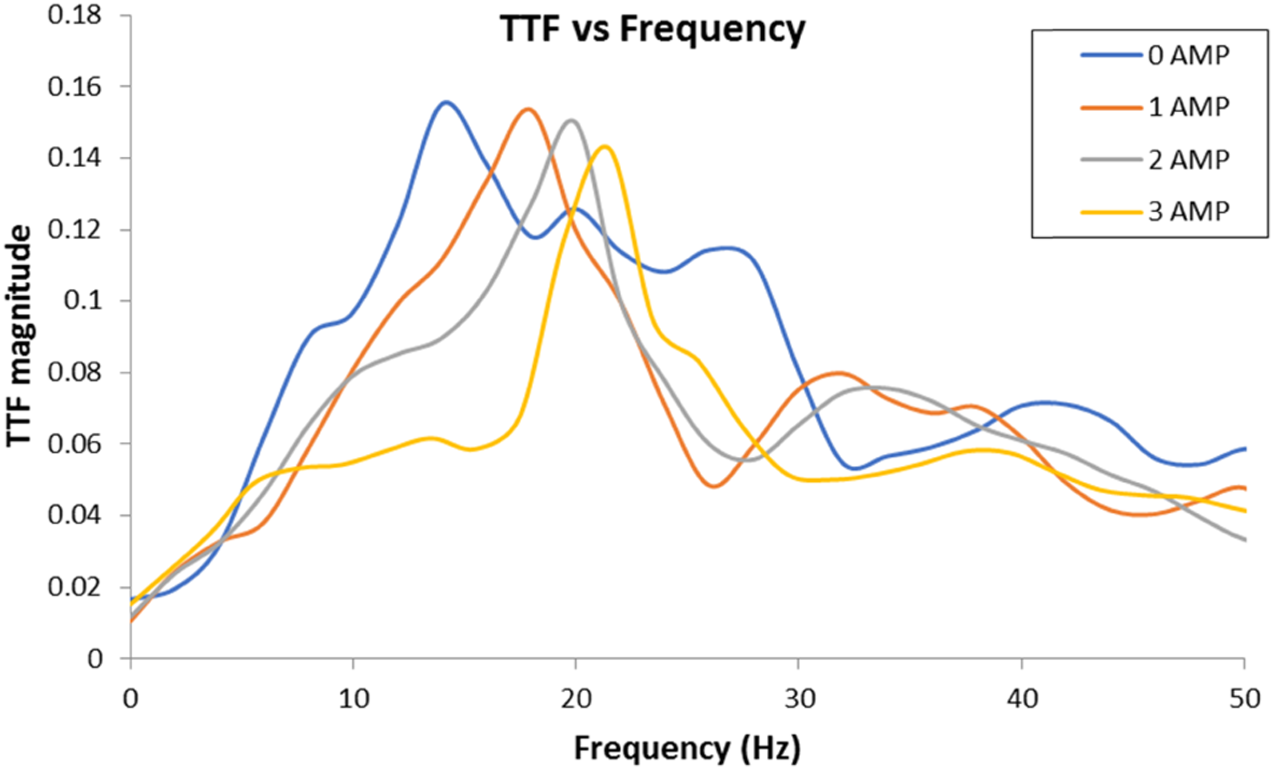
The 1st natural frequency occurs at 13.9 Hz with TTF magnitude of 0.15,522 rad/N.m.s2. At the same frequency, the magnitude drops to 0.1117 rad/N.m.S2 under magnetic field produced by 1 A coil current. As the magnetic flux increases, the magnitude of TTF decreases. This means that a minimum magnitude of TTF can be achieved at a certain excitation frequency by changing the magnetic field, leading to torsional vibration isolation. When the current value is 1 A, the resonance frequency becomes 17.5 Hz. The natural frequency of the system reaches 21.45 under magnetic field produced by 3A current passing electromagnetic coils. The system’s natural frequency increases as the applied current increase as shown in Figure 19; the TTF curve is being shifted to the right. This is due to the stiffening effect of MRE under a magnetic field. The natural frequency of the system versus magnetic field.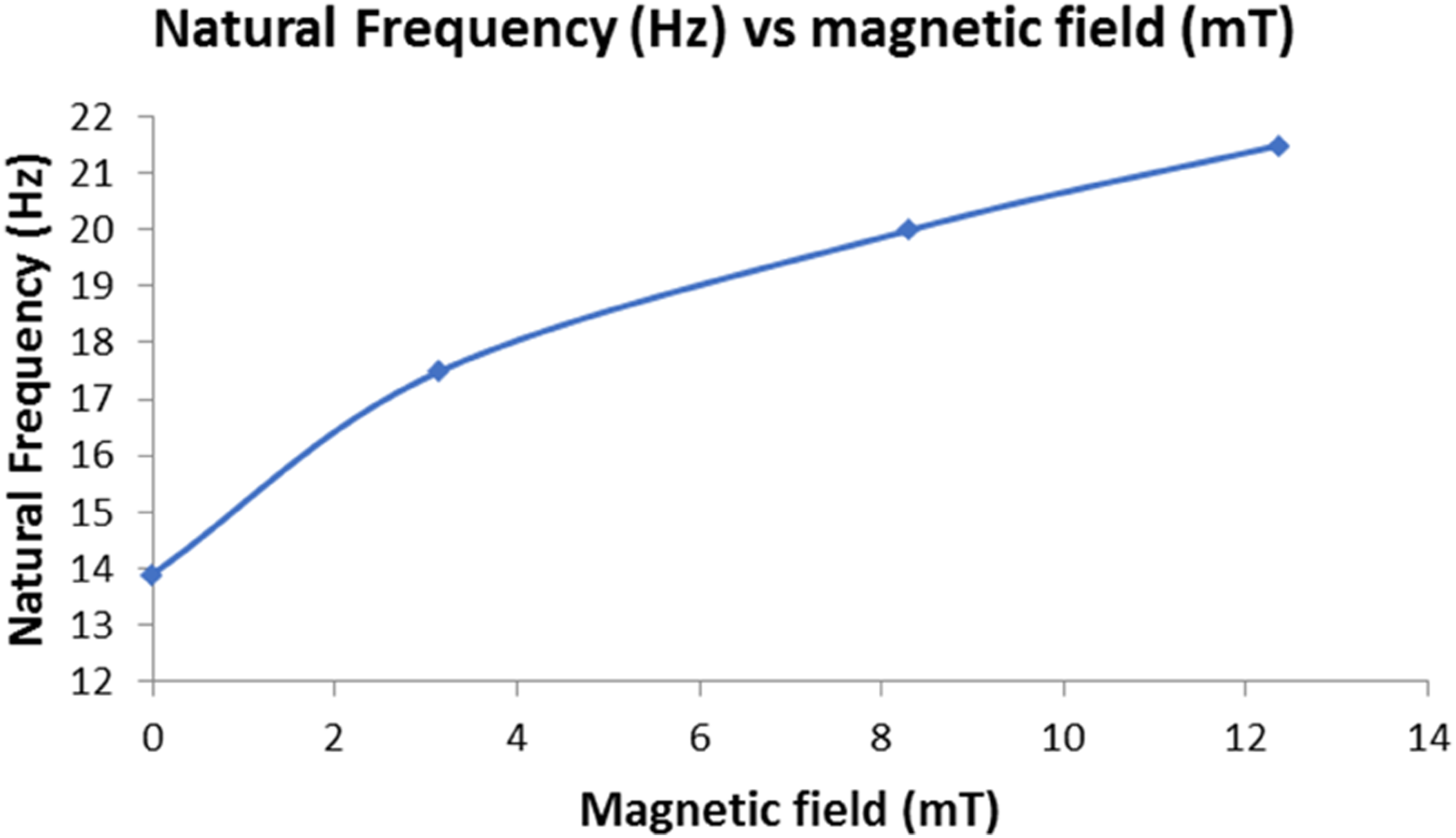
The values of the torsional stiffness of the MRE for the applied current range are calculated using equation (20), where the inertia of the disc is Torsional stiffness of MRE versus applied current.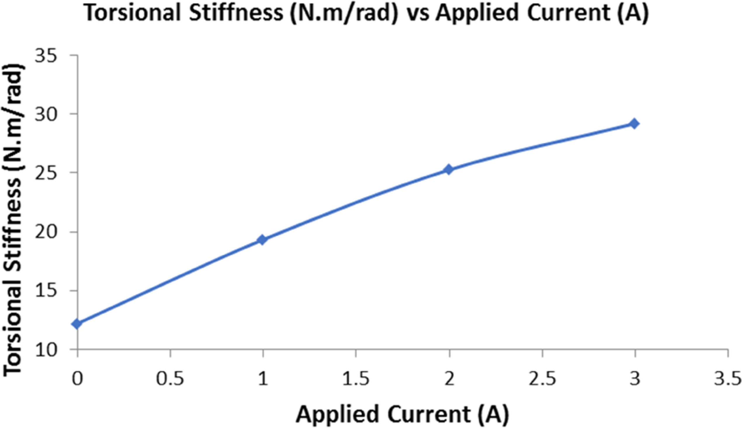
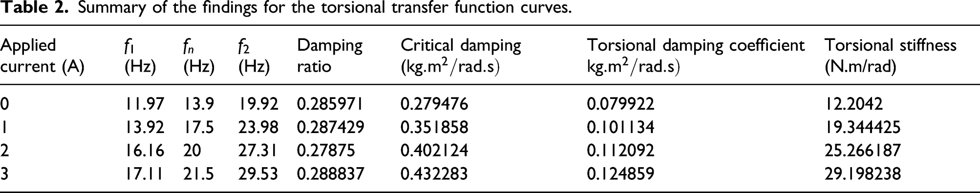
The damping coefficient values are obtained from the transmissibility curves by using the half-power bandwidth method as in equations 20 and 21 highlighted in the methodology. Figure 21 shows the values of the MRE torsional damping coefficient to the applied current. Results show small changes in damping characteristics of MRE under magnetic field; changed from 0.079 kg.m2/rad.s to 0.12 kg.m2/rad.s when the current reached 3A. This finding agrees with the literature that the damping characteristics of MRE are not influenced much by magnetic fields. A summary of all results in terms of MRE torsional stiffness and damping coefficient is shown in Table 2. Damping coefficients of MRE versus applied current. Summary of the findings for the torsional transfer function curves.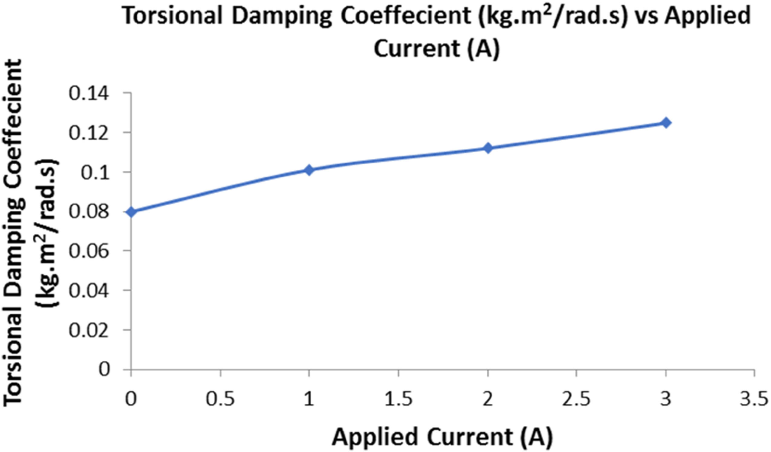
Continuous rotation test results
This test examined the MRE effect on torsional vibration reduction when the system is under continuous rotation. The methodology of this test was explained in details in Continuous rotation test methodology. The motor started to rotate when the voltage value is 5 V. This is due to the system’s load as it consisted of shafts, slip ring, MRE coupling and the disc attaching the drill bit. The motor was controlled with a voltage range of 5–7 V with an increment of 0.25 V. The tachometer was used to measure the speed of the shaft. At each time, the applied current to the electromagnetic coil was varied too (0A–3A). The relationship between the input voltage and the rotation of the shaft (RPM and frequency) is shown in Figure 22. The trend shows a direct link between the input voltage and the rotation of the shaft. Rotation of the shaft versus input voltage.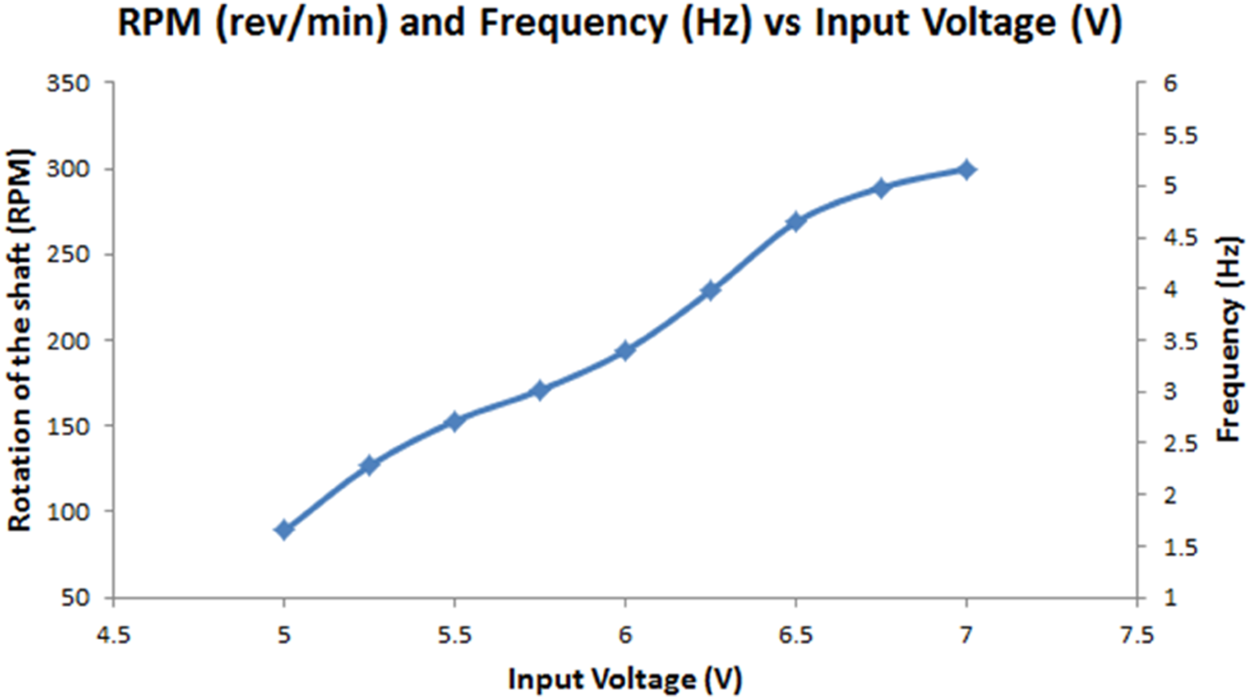
After doing the test at each input voltage (fixed RPM), the readings of both accelerometers were delivered to the DAQ and converted to the frequency domain using FFT. FFT plots were plotted for each value of the excitation frequency, and the amplitude was noted at that particular frequency (frequency of rotation). The FFT plot presents the amplitude to a range of frequencies. Figure 23 shows the processing of the data analysis. Signal processing and data analysis methodology in the continuous rotation results.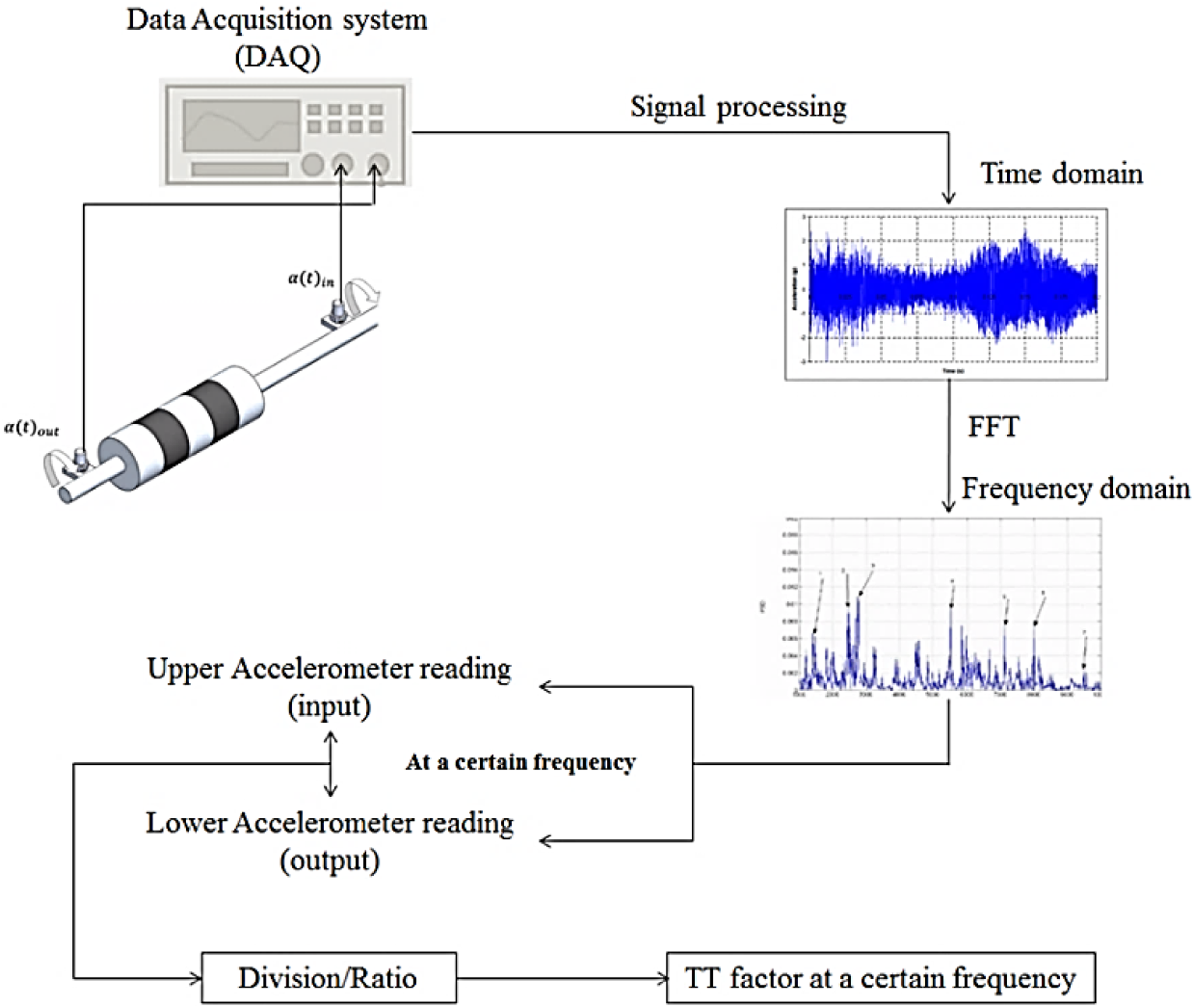
The analyses started with obtaining the time-domain data. Results show that the amplitude in both locations is different. Figure 24 shows the time domain of both accelerometers readings at a motor input voltage of 5V. These readings are the angular acceleration, as explained previously. It is shown that there is a difference in the readings where the red curve shows the amplitude of the upper accelerometer and the blue curve represents the lower accelerometer amplitude. It is shown that the red curve overweighs the blue one illustrating that the vibration is higher. Also, the amplitude for the red curve is higher than the blue curve, which can be observed as shown in Figure 24. Time-domain spectrum for the angular acceleration in upper and lower accelerometers.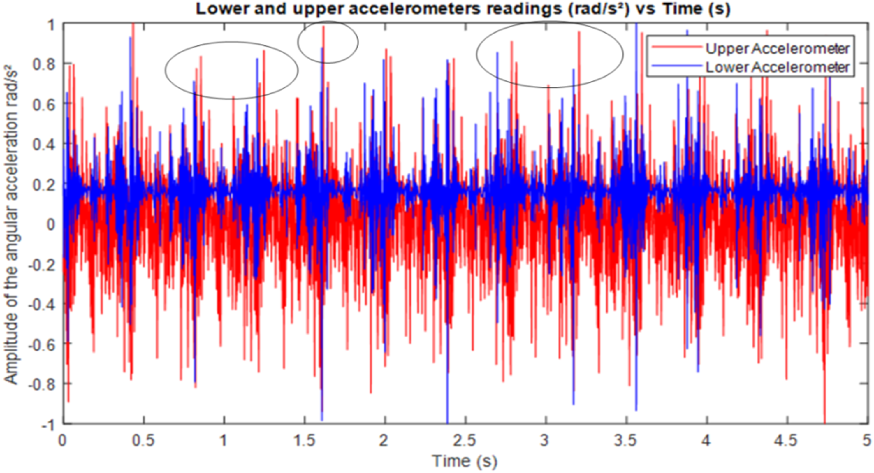
Angular acceleration transmissibility factor at applied current of 0A, 1A, 2A and 3A.
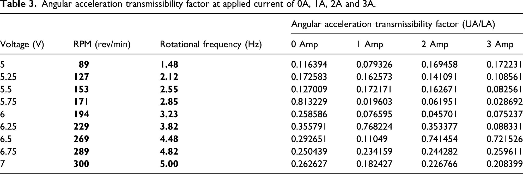
According to the results, the use of the MRE affects the drilling system as a whole. However, the effect of the MRE is present when the load is transmitted from the motor to the drill bit. In this case, the assumption made is that the drill string is rigid, which means that the upper accelerometer reading is the same as the motor’s output. This illustrates that the MRE can reduce the amplitude of rotation when the magnetic field increases for an applied current of 0A–3A. For this specific range, MRE responded well to the magnetic field increase and it could reduce torsional vibration during rotation.
The upper and lower accelerometers versus frequency readings are plotted to observe the effect of the MRE in vibration isolation. Figure 25 represents the angular acceleration for both accelerometers plotted against the range of the frequencies for different applied current supplied to the electromagnetic coil. It is found that the amplitude of rotation before the presence of MRE is higher than the amplitude of rotation after it. Angular acceleration for upper and lower accelerometers (before and after MRE) for the applied current of (a) 0A, (b) 1A, (c) 2A and (d) 3A.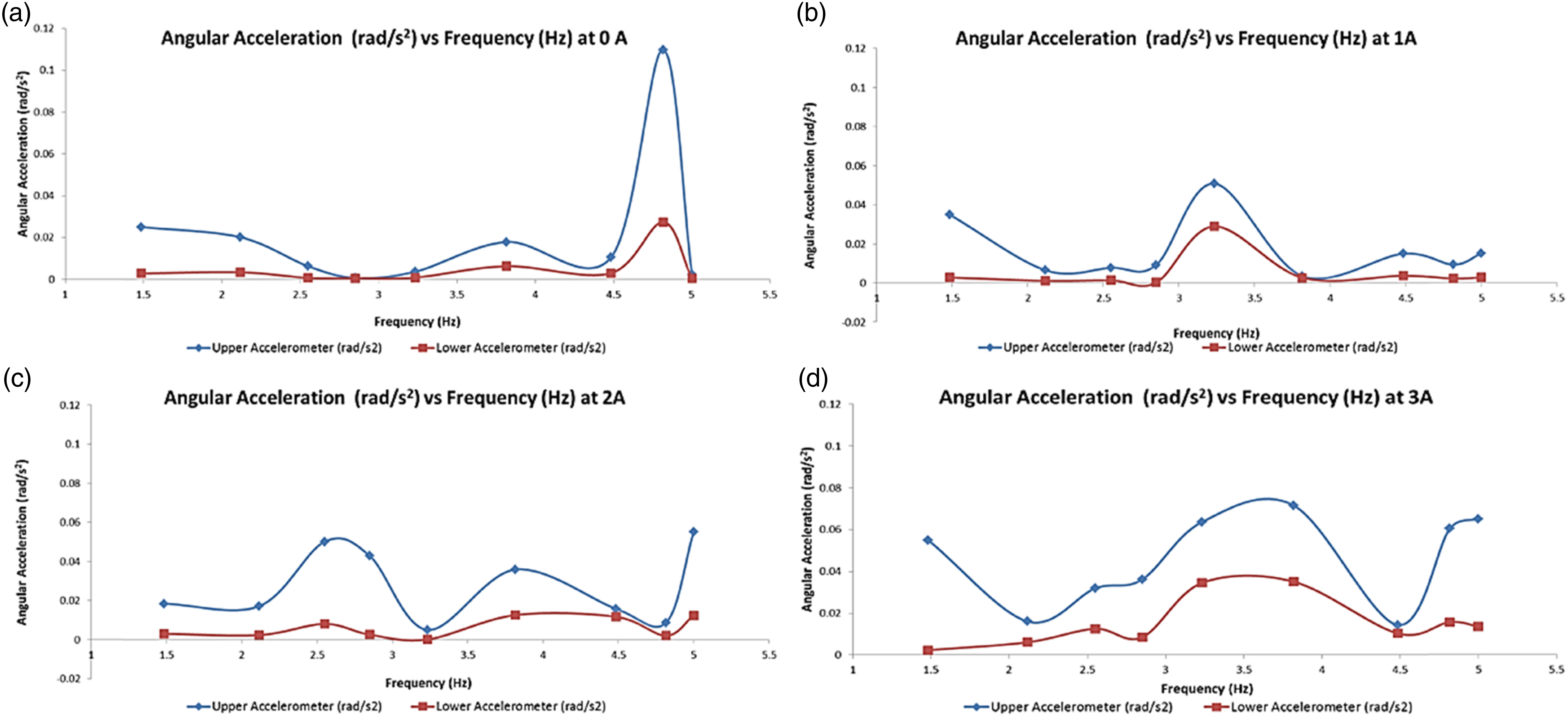
Similar trends are observed in Figure 24 for the readings of upper and lower accelerometers at a certain current applied. The amplitude of the upper accelerometer is higher than the amplitude of the lower accelerometer, which shows that the rotation is more convenient and calm. The obtained data for the experiment when no magnetic field is applied (0 Amp) in Figure 24(a). It is shown that the amplitude before and after the presence of the MRE is different. For example, the amplitude of rotation (angular acceleration) for the upper accelerometer is 0.02518
The torsional transmissibility factor is plotted with respect to the frequency for all cases as in Figure 25. It is observed that the curves are being shifted to the right. This is due to the stiffening of the MRE when the applied current increases. The transmissibility factor is 0.77 when the applied current value is 1A; the natural frequency at this current is 3.8 Hz. At this frequency, the transmissibility factor drops to 0.39 when the applied current is 2A. This means that a minimum transmissibility factor can be achieved for this system, and the current variation is sufficient. The peak frequency, in this case, does not represent the resonance frequency because it was obtained from the impact test, which was about 13.9 Hz. The peak, in this case, represents one of the frequencies during the rotation of the motor. The power supply unit used in this test has its maximum voltage output of 12 V; the system’s resonance frequency was not achieved. The peak indicates that MRE damping properties change slightly, which agrees with the literature and the previous impact test (Figure 26). Torsional transmissibility factor versus excitation frequency for the continuous rotation test.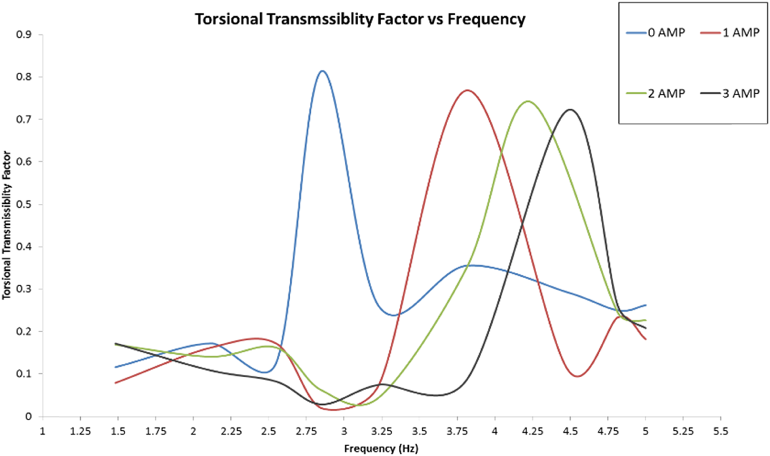
Conclusion
In this work, MRE based torsional vibration isolator was fabricated. A prototype test rig for a drilling system is developed to utilize MRE as a semi-active torsional vibration isolator. The flexible coupling is attached to shafts to represents the drilling application. This paper showed a proof of concept, and the epoxy binding used is sufficient to ensure that the aluminium pieces are attached firmly to the MRE. The mathematical model of the system was derived. The angular displacement transmissibility equation was obtained. Two tests were implemented on this system. The efficiency of the MRE was tested statically and dynamically, and results revealed that MRE can isolate vibration in the torsional mode. The impact hammer test was conducted in order to obtain the torsional transfer function (TTF), and it was found that the resonance frequency happens at a low range of frequencies. Impact hammer is used for broadband excitation. The response it measured for different magnetic flux to find broadband torsional vibration reduction. The system’s natural frequency is shifted from 13.9 Hz to 17.5 Hz when the 1st magnetic field is generated. The change in the torsional stiffness of MRE was considerable as it increased from 12.2 N.m/rad (No current) to 29.2 N.m/rad when the current reached 3 A. Results shows small changes in MRE damping characteristics when exposed to a magnetic field; from 0.079
The continuous rotation (dynamic test) was performed on the system at different frequencies. Results showed that there is a change in the angular acceleration amplitude before and after the presence of MRE. From time-domain, it was shown that there is a difference in the readings and then using FFT, the frequency domain was obtained in order to catch the amplitudes at certain excitation frequencies. Results showed a reduction in vibration transmissibility factor while rotating at the same speed for each value of current applied. The use of MRE as a torsional vibration isolator in a prototype drilling system is demonstrated in this article. Improvements can be made by applying this methodology to a real drilling machine by redesigning the coupling and the binding technique. For example, an external finger can be attached to hold the MRE on the drilling machine.
Footnotes
Declaration of conflicting interests
The author(s) declared no potential conflicts of interest with respect to the research, authorship, and/or publication of this article.
Funding
The author(s) disclosed receipt of the following financial support for the research, authorship, and/or publication of this article: This study is partially supported by Qatar University International Research Collaboration grant (IRCC-2020-017) and The Open Access funding provided by the Qatar National Library.