
Abstract
In aerospace applications, most of the components are made of composite materials due to the high strength-to-weight ratio. However, those composite structures are poor in sound absorption; for instance, payload fairing used in the launch vehicle system experiences broadband noise. Tuned Helmholtz resonator (HR) is being used to control few dominant low frequencies, and other frequency is left untreated. In this study, the acoustic mode of the rectangular cavity has been suppressed by a novel design of integrated passive elements (IPEs), which comprises a Helmholtz resonator, micro-perforated panel, and polyurethane foam. The proposed design reduces the noise level in Low-Mid-High frequencies, which is more efficient than passive elements used to control a single target frequency. The integrated passive components fabricated using the 3D printing technique are tested experimentally in an impedance tube to quantify the sound absorption coefficient, and the results are compared with the theoretical result. Further, the study presents a simplified approach for numerical simulation of fabricated samples coupled to a rectangular cavity system, which is validated experimentally. The overall sound pressure level (OSPL) results of the proposed design achieve 4–6 dB noise level reduction in
Introduction
Composite structural members used in several applications are having very poor sound absorption capability. Broadband noise associated with payload fairings of a vehicle launch system is a typical example. However, these structures should be capable of suppressing low-frequency noise (near 100 Hz) and also mid-high frequency noise (200–1000 Hz) effectively. It is well known that still low-frequency noise mitigation is challenging and demands a novel solution. 1 In traditional methods, resonators or an array of resonators control the noise associated with the desired frequency by changing the parameters such as neck length, neck area, and cavity volume of the resonator. But their advantages lie only in the low-frequency region (<500 Hz). HR works similar to a spring-mass system, and it can be tuned to the desired frequency. Fahy and Schofield 2 carried out primal work in an HR-coupled cavity system and shown the optimal position and geometric parameters for which a resonator can attain a maximum value of target eigen frequency. For better noise reduction in an acoustic cavity, one can replace the resonator with a broadband absorber at this position, which is highly desirable in an aerospace application where the space constraint is needed. HR and an array of HRs are used in many studies to reduce low-frequency noise in the enclosures.3–6 Another way of mitigating broadband noise is embedding resonators in open-cell PU foam or increasing the thickness of porous material. However, in aerospace and space vehicles applications, the size and mass of the structural components play a vital role.
Apart from HR, several researchers proposed micro-perforated panel (MPP) as a good candidate for the noise reduction in fairings. 1 For sound absorption enhancement, double layer of MPP’s7–9 and an array of MPPs with different depths of air cavity 10 are used. Some researchers analyzed the influence of porous materials for noise control in the coupled cavity systems. In general, the numerical analysis of an acoustic enclosure is carried out using the finite element (FE) and boundary element (BE) methods. Nefske et al. 11 made an outstanding review on the use of FE method for acoustic analysis of an enclosure. They intend to reduce the frequency ranges from 20 to 200 Hz for the known excitation forces and the noise source generated by structural excitation of the wall. Kopuz and Lalor 12 performed the FE and BE analysis in a closed-rectangular cavity and studied the acoustic response of the boot compartment inside the car cabin. Atalla and Panneton 13 studied the effect of layered porous material in a rectangular cavity system for noise reduction. Sarıgul and Kıral 14 evaluated the cabin’s sound pressure level (SPL) treated with acoustic lining porous material using the BE method. The harmonic excitation is given in the acoustic field in terms of the Helmholtz equation. Identically, Mohanty et al. 15 evaluated SPL at the right-side ear in a car cab, where the harmonic excitation was applied at the mounts from measured acceleration data. The modal analysis and natural frequencies of the cab are obtained using FE and BE methods. Li and Cheng 16 investigated vibro-acoustic behavior of a coupled system with a flexible panel and calculated the mean quadratic velocity of the vibrating plate and overall SPL of the rectangular cavity with a tilted wall for geometrical distortion. Passive materials are widely used as lining materials for enclosures.
Moreover, the usage of porous material leads to sound absorption and also helps to improve sound transmission loss when applied on a duct or an enclosure. Babu and Padmanabhan 17 used glass wool with different types of macro-perforated patterns to perform noise control in the rectangular enclosure using FEM. Rumpler et al. 18 presented finite element formulation for porous material in the coupled vibro-acoustic system using the reduction method. Nair et al. 19 investigated the effect of damping and resonator volume fraction coupled to the cylindrical cavity and observed in 5 dB noise suppression in the first dominant frequency. Egab and Wang 20 carried out psychoacoustics studies on the cavity and interior trim elements using an impedance mobility approach.
Fractal geometry offers a new perspective on geometric modeling and helps to model porous structure and then print them using 3D printing technology. It can realistically model natural things and live beings, which is potentially beyond Euclidean geometry’s capabilities. 21 It is also reported that fractal approach enhances physical, mechanical, and electrical properties of composites significantly.22–24 Self-affine form (also known as self-similar shape) and fractal dimension are two fundamental elements in fractal geometry. It’s been utilized in the telecommunications industry to build antennas and other equipment that ensure simultaneous multi-frequency transmission. 25 To overcome the drawback of continuum beam theories to account of porous property, fractal theory is applied to reveal the low frequency characteristics. 26 He et al. 27 adopted fractal model for one step accurate solution to obtain low frequency property of oscillators. 3D printing technologies that smoothly integrate different materials into objects will enable the creation of new or enhanced characteristics and advance 3D printing as a mainstream method of manufacturing functioning and smart products. 28
Recently, the advantage of additive manufacturing was used to produce complex shapes in thin structures. The prime work on 3D-printed acoustic materials is performed by Liu et al., 29 and they investigated the sound absorption capability of 3D-printed MPP as a front layer in multi-layer configuration. Arjunan 30 studied the 3D-printed noise-canceling passive structures tuned for targeted frequencies based on wave destructive interference principle. For wideband absorption, Yuvaraj and Jeyanthi 31 proposed countersunk perforation in MPP using fusion deposition modeling and also developed multi-layer configuration with the different airgap. Sailesh et al. 32 presented bio-degradable thick micro-perforated panels with varying cross-sections of perforation prepared using 3D printing. They reported that printed samples show better sound absorption than conventional uniform hole perforation.
Also, studies showed the integration of HR and MPP to attain better sound absorption over a wide range of frequencies. Park 1 introduced the theory for wideband absorbers in a low-frequency regime through MPP absorber backed up with HR. Gai et al. 33 conducted experiments on an alternate absorber, in which an MPP mounted with HR is used to enhance the sound absorption capability of single layer MPP. These studies confirm the demand for broadband absorbers and the usage of MPP and HR, which correspond to mid- and low-frequency absorption. In contrast, for high-frequency, the inclusion of porous material is essential. So the keen idea of this study is to design and develop a single system of broadband absorbers composed of HR, MPP, and PU foam using additive manufacturing.
Though the quantum of literature’s available on applying passive material to the cavity system, the experimental studies on integrated passive element-cavity coupled system and its influence on noise reduction over range of frequencies have not been explored. This study proposes a novel method by integrating Helmholtz resonator, micro-perforated panel, and polyurethane foam to control noise in a wide range of frequencies in a rectangular cavity. The complex shape of HR integrated with MPP and PU foam can be prepared successfully using 3D printing technology. The 3D-printed samples are tested using the impedance tube to analyze the sound absorption capability of the proposed integrated passive elements (IPEs) over a wide range of frequencies. Further, the array of IPE is coupled to the rectangular cavity, and its influence over OSPL is also studied.
Theory
To calculate the overall sound absorption co-efficient of IPEs, it is necessary to characterize the individual impedance associated with HR, MPP, and PU such as ZHR, Z
MPP
, and Z
PU,
respectively. Figure 1(a) depicts the equivalent electro-acoustic analogy of the proposed IPE system, and Figure 1(b) shows the schematic representation of absorber configuration, which comprises HR_1 connected in series with MPP_2 and also PU foam_3 kept behind MPP, so the sound waves propagate through the hole will communicate. The sound waves strike on the structure’s surface similar to the source of sound pressure 2P, and ρc0 is the internal air resistance. Based on electro-acoustic analogy, the total acoustic impedance (Z
Total
) of the IPEs is arrived at by following equation (1) Theoretical and schematic representation of proposed absorber. (a) Electro-acoustic analogy of the proposed IPE system. (b) Schematic cross section view of IPE.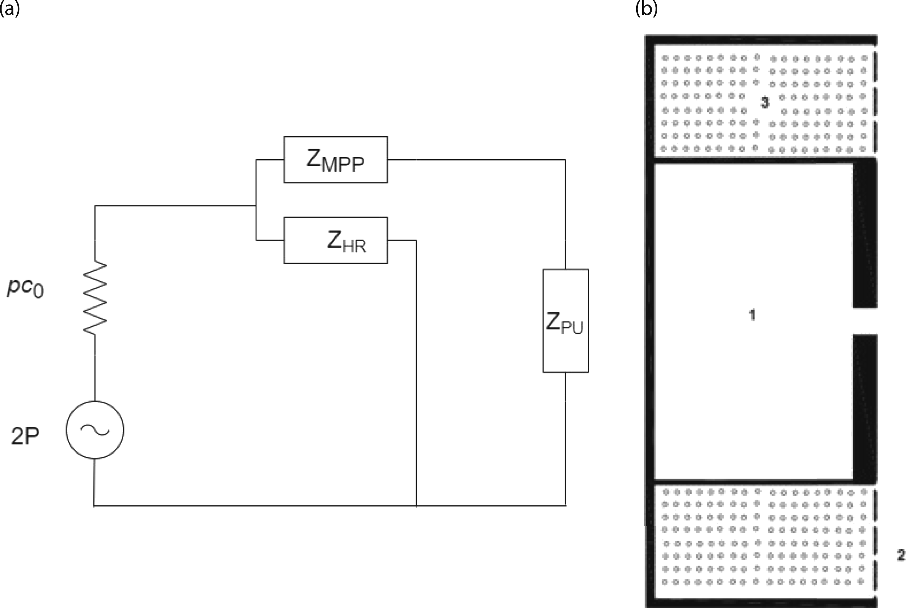

Helmholtz resonator
The Helmholtz resonator attenuates the first dominant low frequency can be tuned by changing the neck length and cavity volume, which typically acts as a spring-mass system. The acoustic impedance of low-frequency passive element HR 9 is calculated by an analytical method using the following relations.
Acoustic resistance (

Acoustic reactance (

Acoustic compliance (


Micro-perforated panel
The impedance of mid-frequency passive element MPP is calculated using Maa model 35 by the following equations:
Acoustic resistance (


Acoustic reactance (


Acoustic impedance (

Porous material
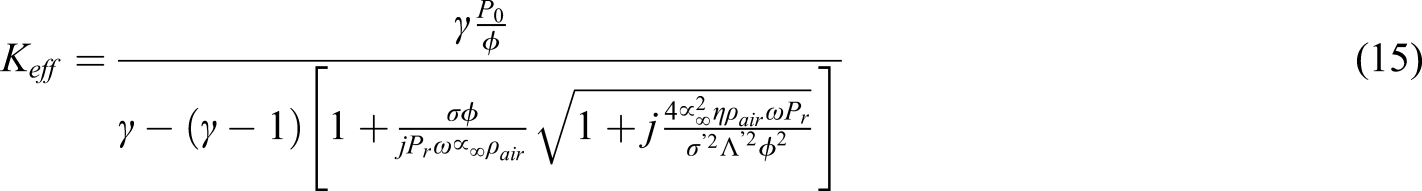
The acoustic impedance of PU foam porous material is calculated using Johnson–Champoux–Allard (JCA) model,
36
which involves five non-acoustical parameters, namely, porosity (


Overall sound absorption coefficient (

Preliminary studies
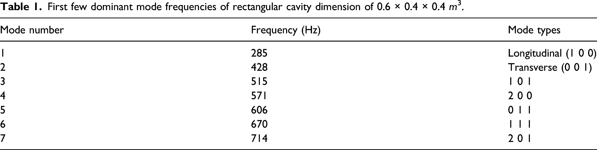
First few dominant mode frequencies of rectangular cavity dimension of 0.6 × 0.4 × 0.4 m3.
Numerical modeling
The primary purpose of this numerical study is to analyze the effect of a resonator coupled to the cavity. It is reported in the literature that 1% of resonator volume to cavity volume is needed for effective noise suppression. In that aspect, numerical analysis is carried out for empty cavity and cavity coupled to single and multiple resonators. Numerical simulation is performed using COMSOL Multiphysics 5.4 to analyze OSPL of empty cavity and cavity coupled to single and multiple resonators, whereas MPPs and PU foam are not considered for numerical analysis in order to avoid meshing complexity associated with modeling of very small size holes, which leads to higher computational time. The following assumptions are made for the study: The whole cavity is modeled as a fluid domain, and the outer region is assigned as a sound hard boundary wall to neglect the fluid–structure interaction. In real-time experimental testing, the cavity is excited by the speaker, whereas in numerical analysis, the speaker is modeled as a monopole point source. The ratio of wavelength to the speaker’s diameter is maintained as 10 for the chosen exciting frequency range.
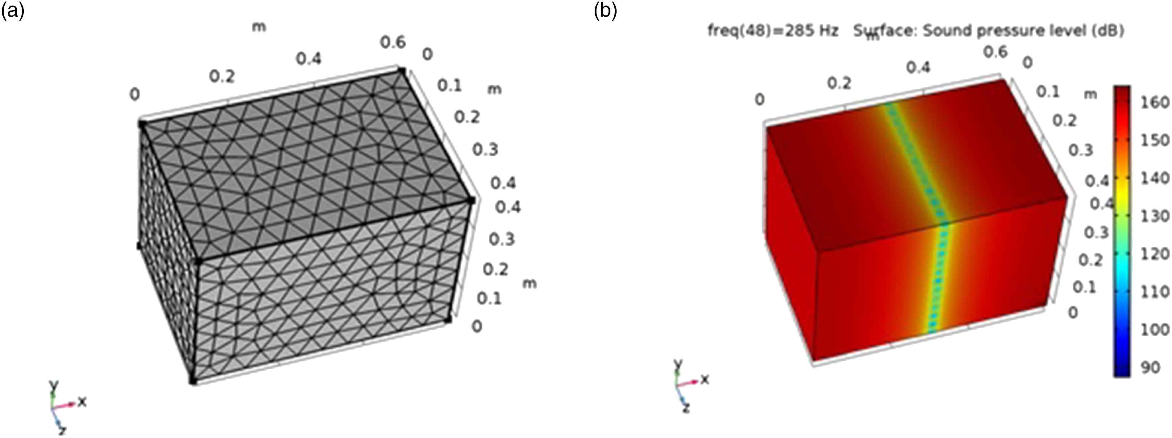
In COMSOL, pressure acoustic module is chosen, which is suited for frequency domain analysis. The 3D geometry of cavity-coupled resonator models is imported to the geometry section in a suitable format using CAD kernel. The in-built materials property of air is applied to the whole domain; unit pressure amplitude is given as monopole point source excitation in the corner of the rectangular cavity. Free mesh made of tetrahedron element is used with user-controlled mesh in the model. The element size is chosen based on six elements per wavelength with respect to maximum working frequency. Figure 2 depicts the numerical analysis of empty cavity a) mesh part and b) first cavity mode. The wavelength corresponding to maximum frequency is obtained by Numerical analysis in COMSOL. (a) Mesh part of empty cavity (b) sound pressure level in empty cavity.
Materials
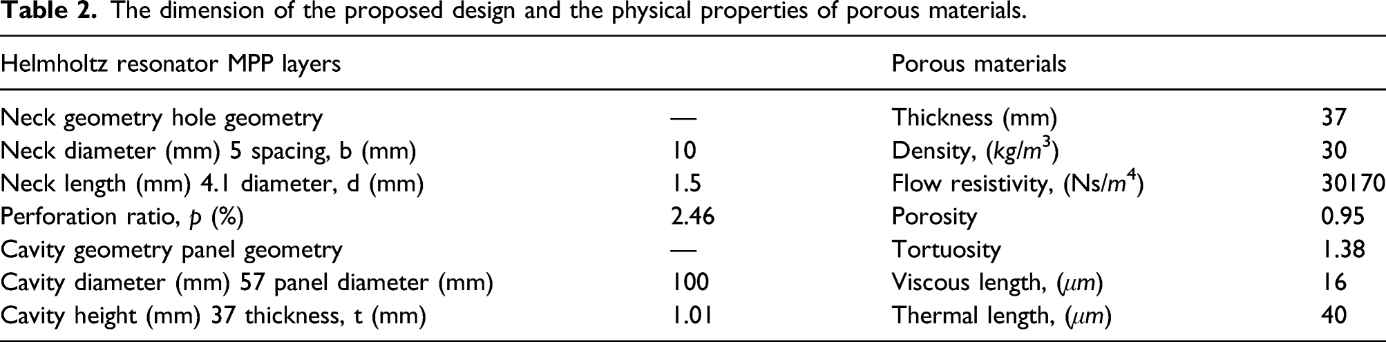
The dimension of the proposed design and the physical properties of porous materials.
Testing
Sound absorption as per ASTM E-1050
To evaluate the noise control capability of the proposed IPEs, experiments are performed in an impedance tube setup as per ASTM E-1050.
37
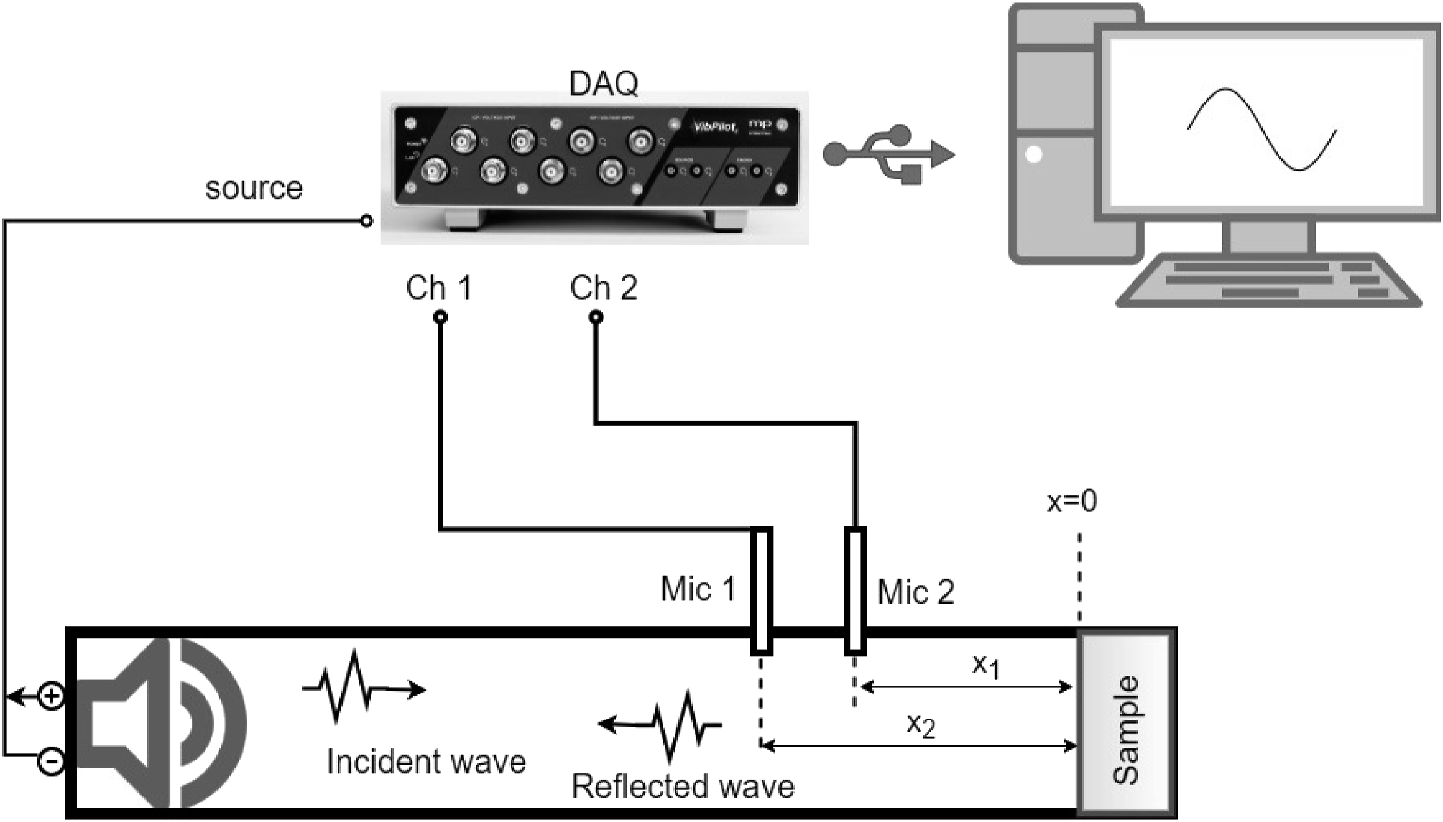
The schematic representation of two-microphone impedance tube is depicted in Figure 3. The periodic random excitation is given as an input from the loudspeaker mounted at one end of the tube over the frequency range of 200–1600 Hz, where the testing sample is placed at the other end. Two 1/2″ Microtech Gefell microphones were used to measure the frequency response function, which are connected to M+P VibPilot DAQ. A 100 mm impedance tube is chosen, which is suitable for measuring frequency range from 200–1600 Hz, and using M+P spectrum analyzer, the time domain data were extracted from measured signal and imported to in-house developed Matlab® Code to compute sound absorption coefficient results. Impedance tube setup.

Finally, the reflection co-efficient and sound absorption co-efficient 

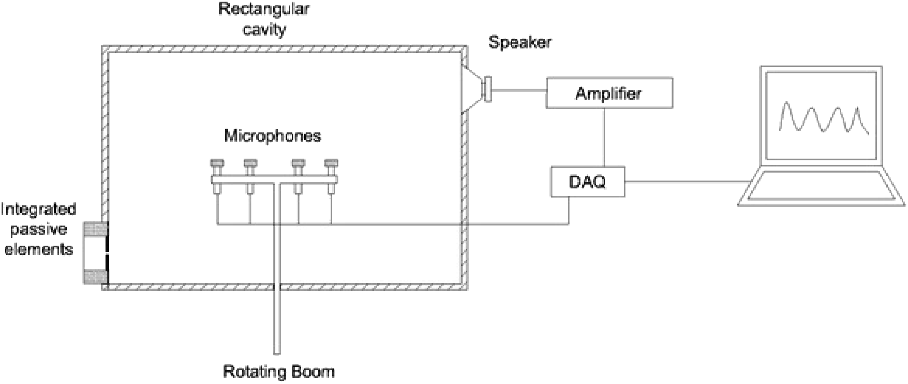
Cavity testing
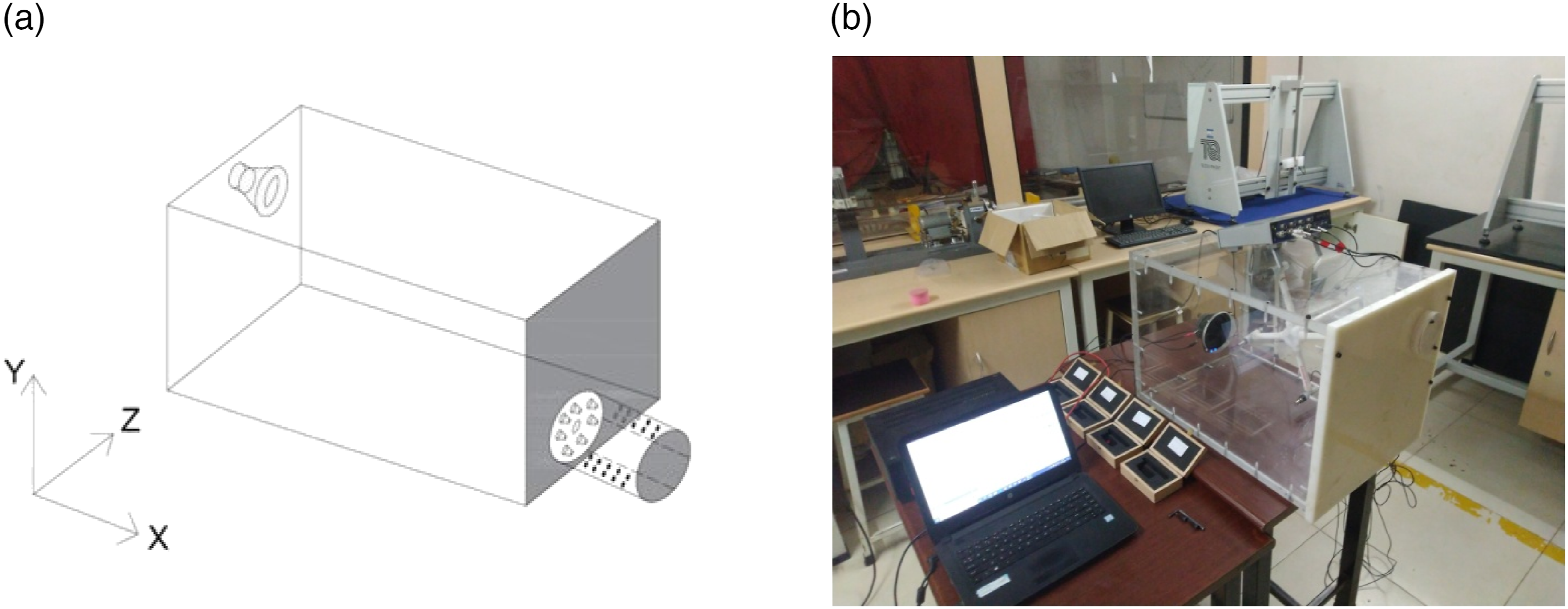
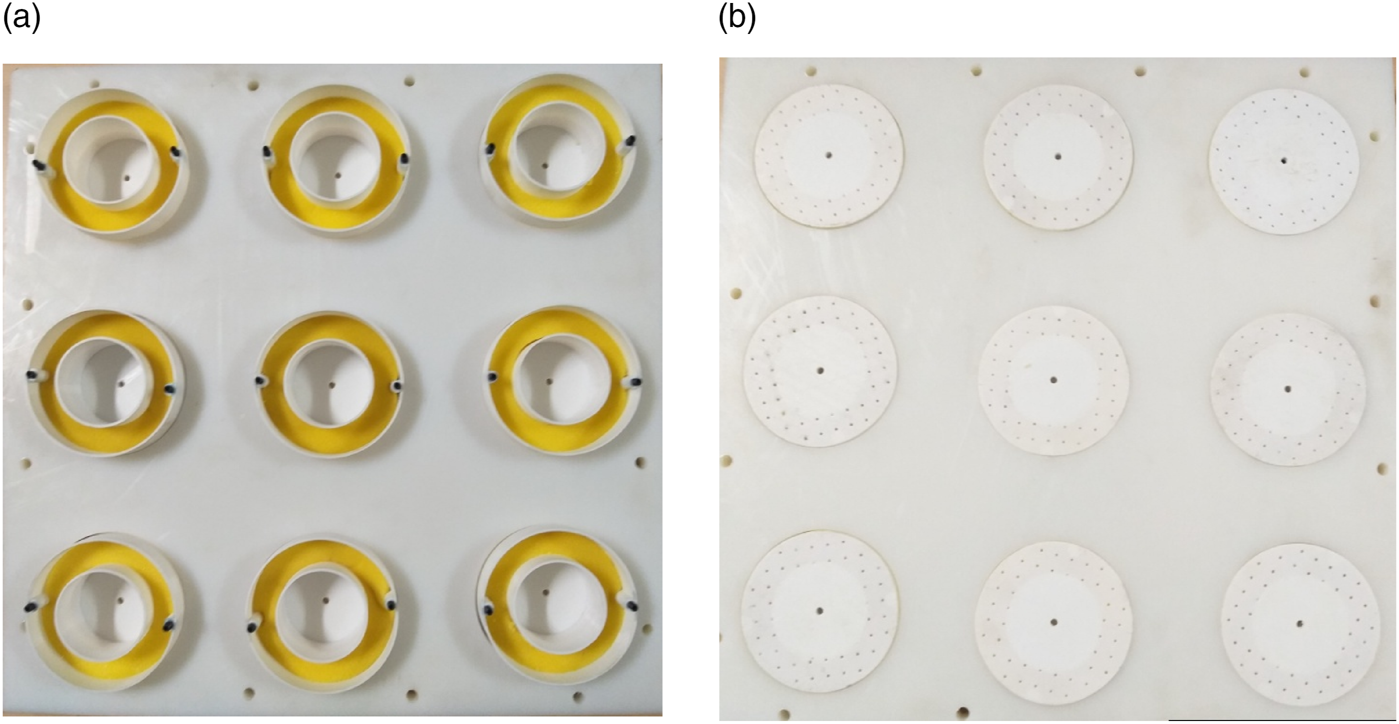
To evaluate the real-time performance of array of integrated passive elements, the samples are flush mounted to the polypropylene plate and fixed opposite the sound source using M5 bolts. The schematic representation of the experimental setup is shown in Figure 4. It comprises a speaker, rotating boom, and microphones. The rotating boom arrangement is used to take multiple readings in radial and axial directions for the effective measurement of OSPL in all regions. The M+P analyzer can produce the source signal and acquire a signal from the microphone transducer. The periodic random signal was excited through speaker from M+P data acquisition system, and the sound pressure created in the cavity is measured by four 1/2″ Microtech Gefell microphones placed at an angle of 90° to each other. After several measurements, the OSPL is obtained by equation (24). The experimental setup and fabricated samples are presented in Figures 5 and 6, respectively. The first cavity mode is along the longitudinal direction, so the speaker and sample placed were in parallel along the length side Schematic representation of experimental testing setup. (a) Schematic representation and (b) image of the experimental setup. 3D-printed sample fixed with polypropylene plate. (a) PU foam coupled with MPP and HR (b) MPP and HR.
Results and discussion
Influence of passive elements on sound absorption
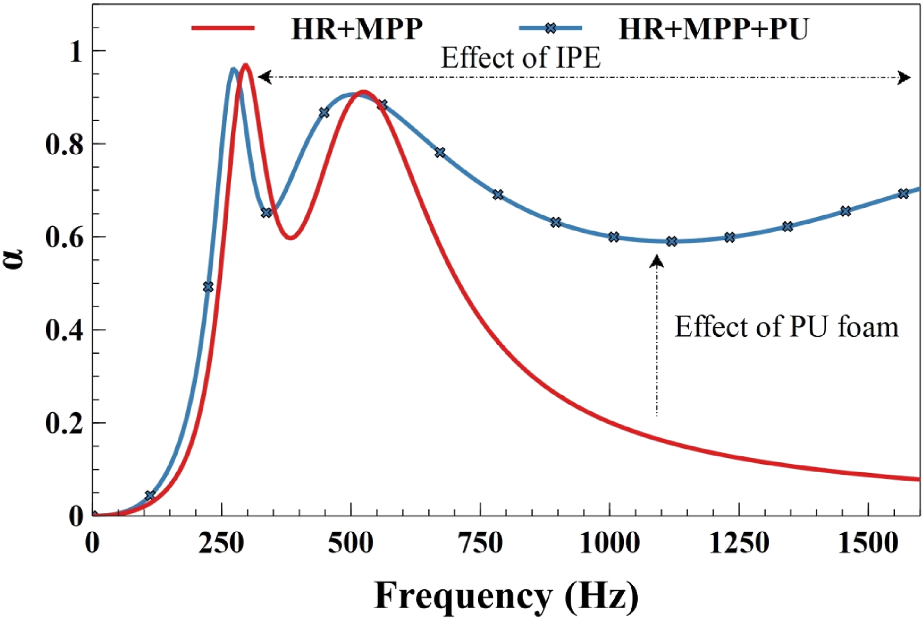
On the basis of cavity modes, the individual passive elements are tuned, and their corresponding theoretical sound absorption results are depicted in Figure 7. The low-frequency peak corresponds to HR, which is tuned for desired frequency of 285 Hz, while the mid-frequency peak dependent on the MPP and the other smooth curve lies in the high frequency is due to PU Foam. To make the individual passive elements to wideband absorber, the passive elements are coupled and results for the same are depicted in Figure 8. At first, HR coupled with MPP, and the simulated results show two peak frequencies and one anti-resonant frequency caused by HR, MPP, and coupling effect. The coupling of HR and MPP was effective till 600 HZ, and some of the frequencies are beyond that, so the PU foam introduced in the system further enhances absorption. Now all the three passive elements are integrated, and the effect of IPE and PU foam is clearly indicated in the plot. Theoretical sound absorption of individual passive elements. Theoretical sound absorption of IPEs.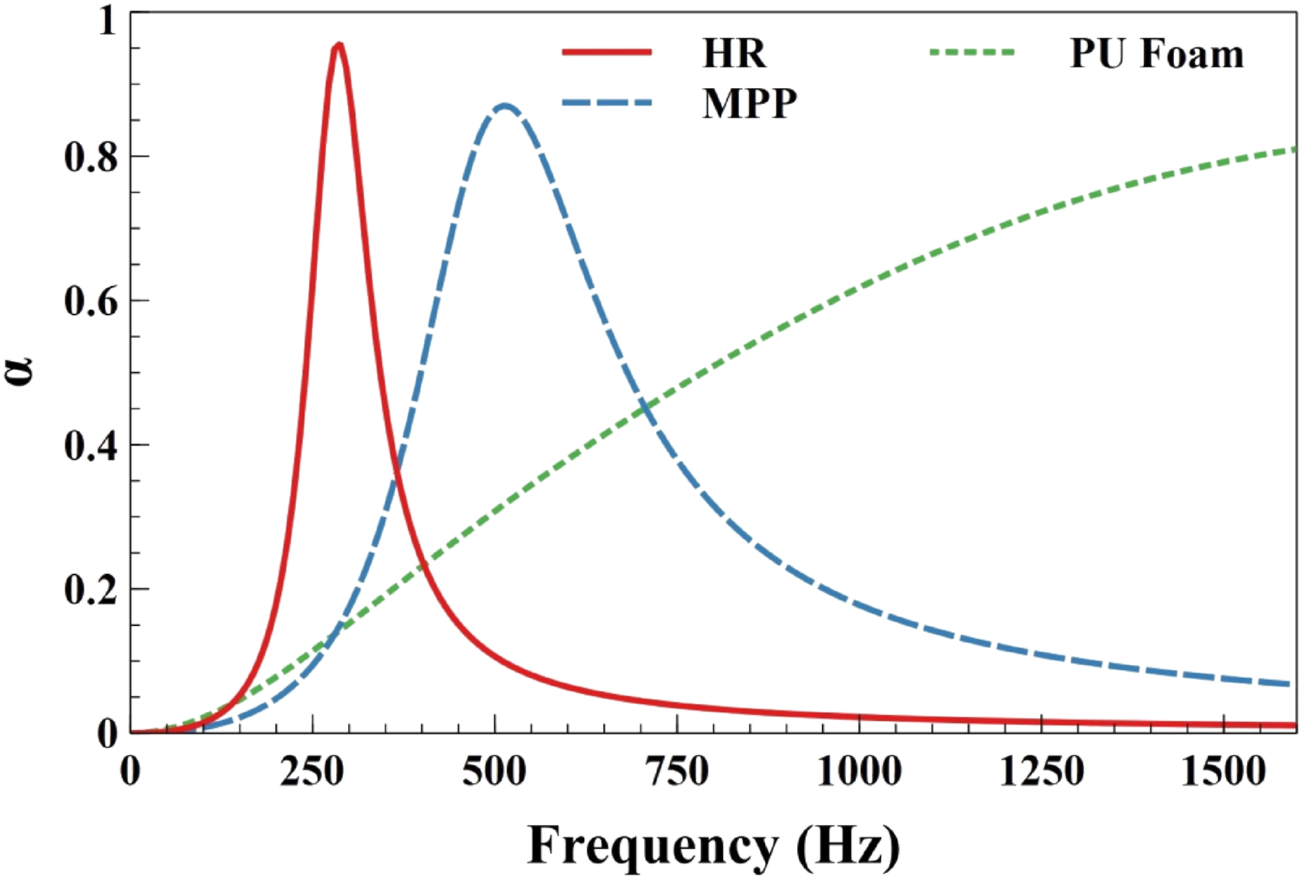
Sound absorption of integrated passive elements
In prior a single integrated passive material fabricated by 3D printing and tested in impedance tube and sound absorption coefficient of the IPEs are given in Figure 9. The results clearly indicate that the proposed IPEs perform their function well in the chosen frequency range. For instance, the tuned HR attenuates more sound in the low-frequency region, MPP at the mid-frequency region, and coupled PU foam at high frequency. It is clear that the proposed IPE can provide better sound absorption over a wide range of frequencies. Comparing the sound absorption coefficient results obtained from theoretical (electro-acoustic principle) and experiment methods exhibits a good agreement with each other. The slightest deviation noticed at few regions is introduced due to non-ideal experiment conditions such as air leaks, gaps between sample edge and tube, and measuring errors by microphones. The overall results indicate that the proposed IPEs possess good absorption at low-mid-high frequency regimes. Sound absorption of integrated passive element. (a) Influence of single and multiple resonators on SPL (b) zoom view upto 400 Hz.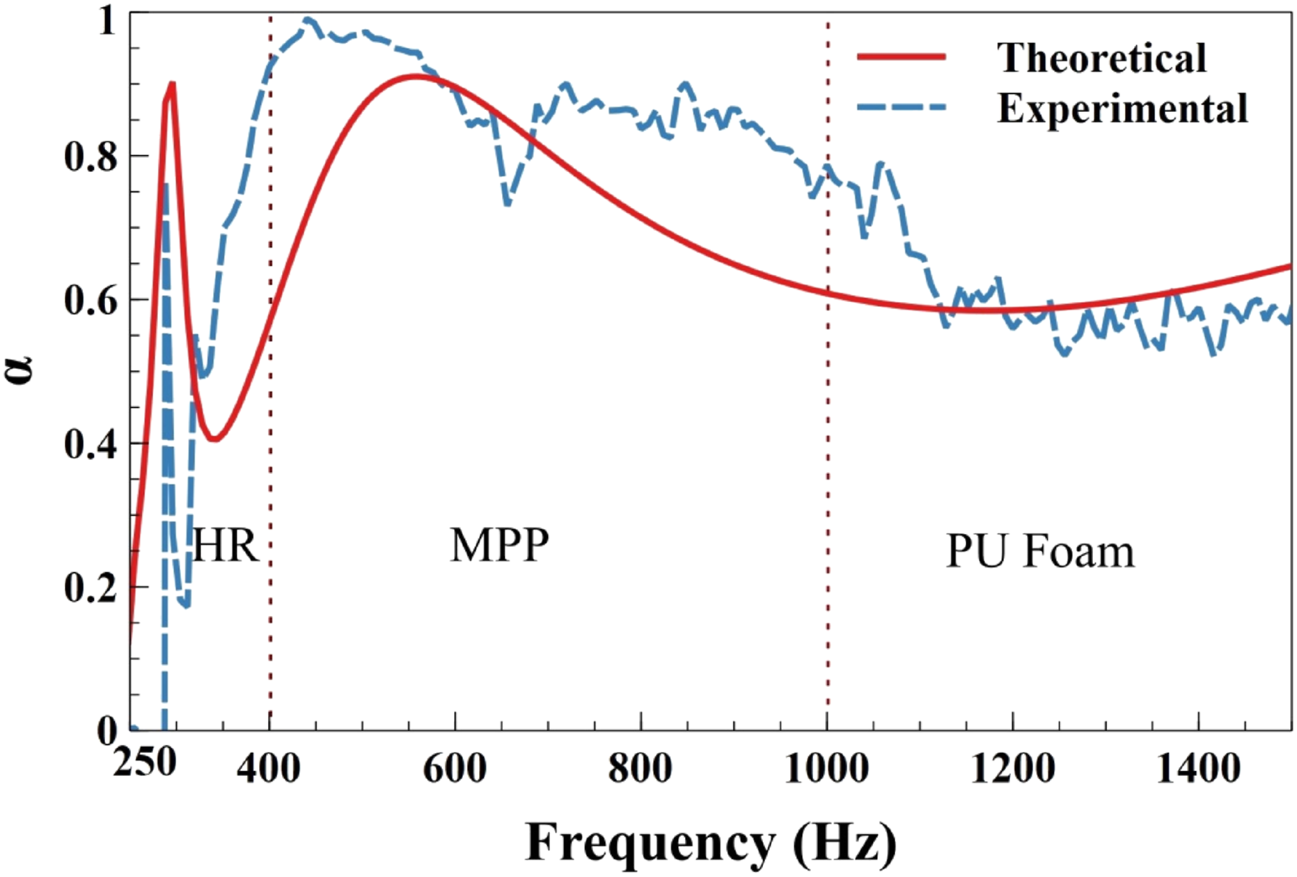
Numerical results of a cavity coupled to the resonator
The numerical simulation of Helmholtz resonators coupled to the cavity is analyzed. Figure 10 shows the comparison of numerical results of a cavity coupled to single and multiple resonators. From Figure 10(a), it is clear that there is no significant variation in the acoustic response of the empty cavity except around the fundamental mode peak due to the introduction of the resonators. After introducing a single resonator in the cavity, a drop in sound pressure is noticed at 285 Hz, which is the fundamental modal frequency of the cavity. This pressure drop induces additional two peaks on either side of the first dominant frequency. The distance between two induced peaks increases as increase of resonator volume to the cavity volume. Similar variation in SPL peaks is observed due to the introduction of multiple resonators also. However, the shift in frequencies corresponding to the peaks is more than the single resonator case depicted in the zoom view of Figure 10(b). Moreover, as expected, the Helmholtz resonator works only at the desired frequency for which it is tuned for, and hence the parameters are valid to print the proposed design. Numerical results of cavity coupled to single and multiple resonators. Experimental results of cavity-coupled integrated passive elements. (a) Influence of single and multiple resonator on SPL (b) Zoom view upto 400 Hz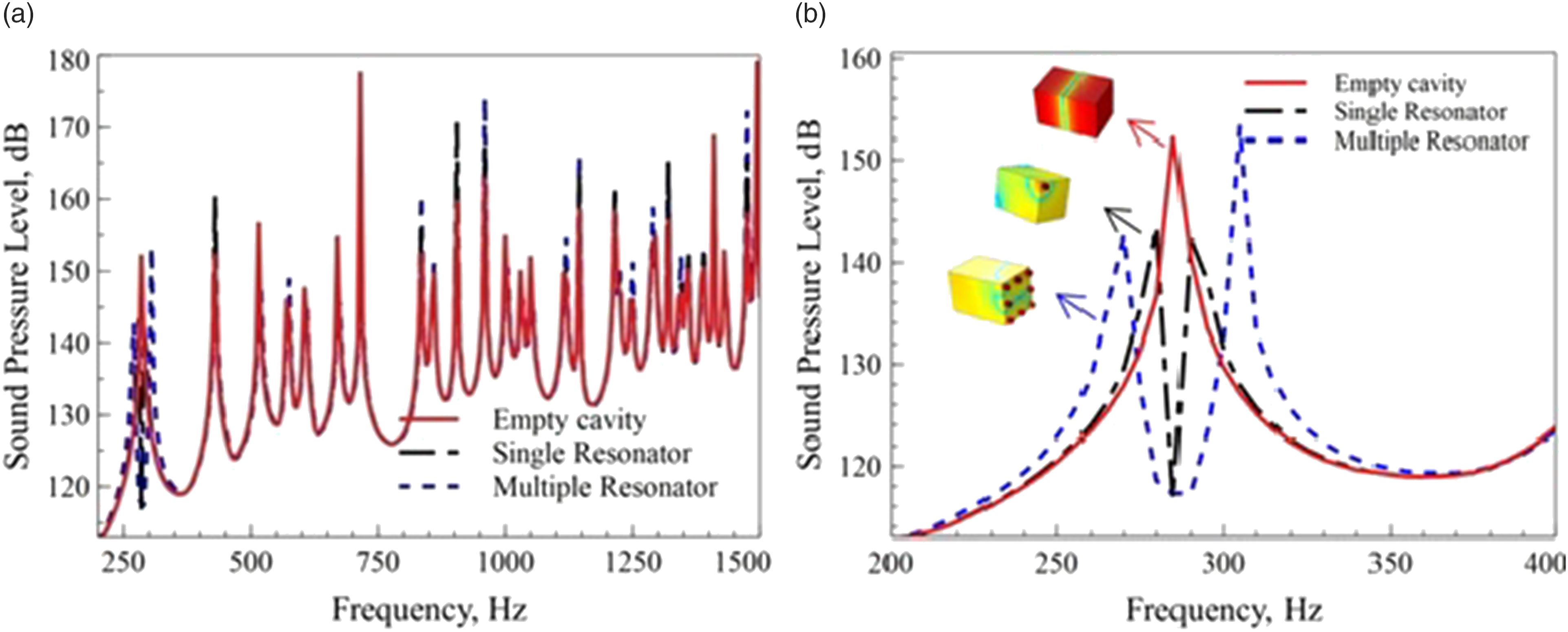
Before coupling IPEs to the cavity, it is necessary to validate the empty cavity results obtained using numerical and experimental methods. A comparison of experimental and numerical results for OSPL of empty cavity is presented in Figure 11. The trend of the plot resembles similar with a slight variation, mainly due to non-ideal conditions, for instance, leakages in the edges. Comparison of experimental and numerical results for OSPL.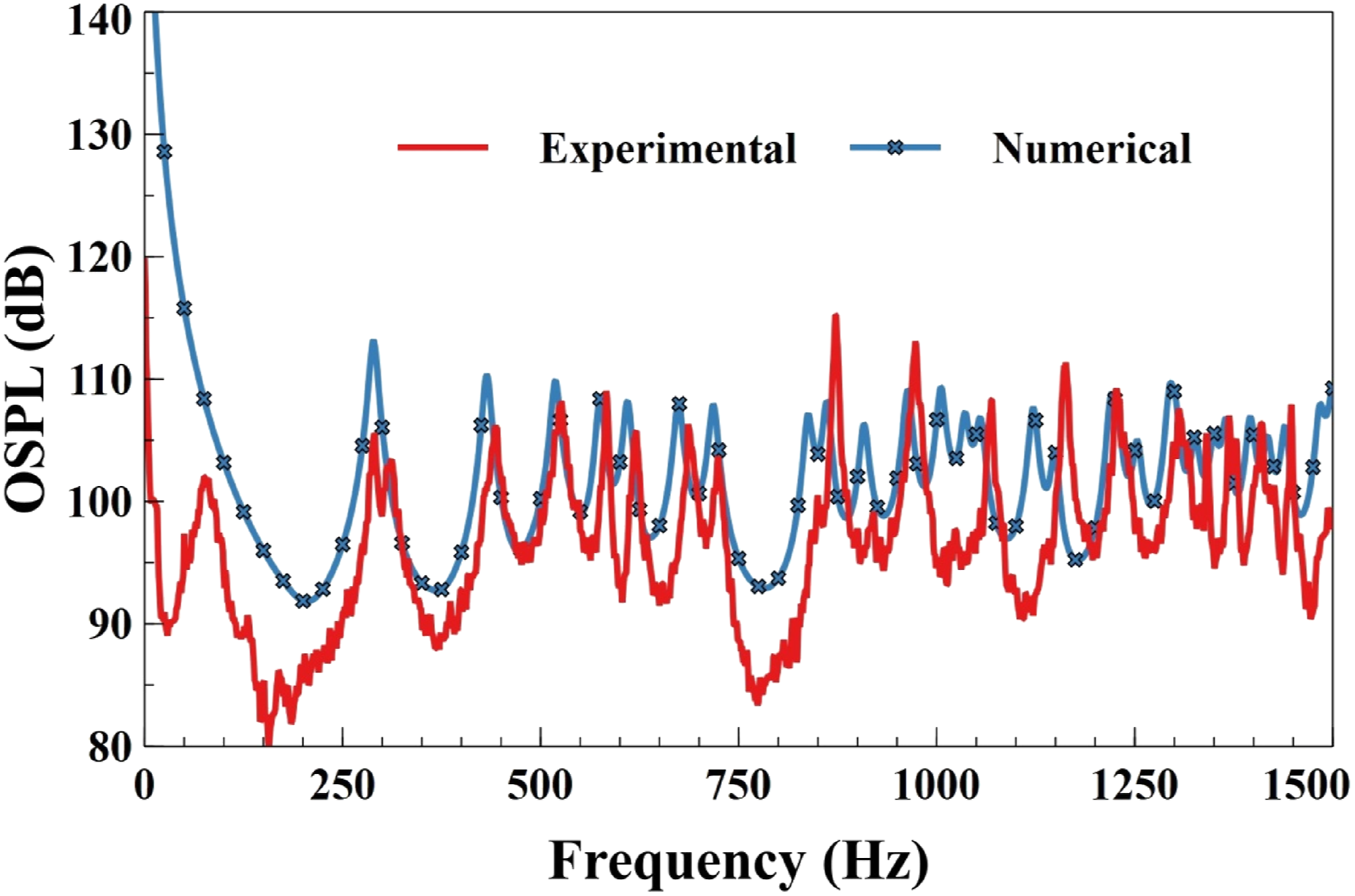
Once the validation is done, the proposed passive elements, as depicted in Figure 6, were coupled to the rectangular cavity in an array of 3 by 3, total nine numbers of IPEs were used for real-time testing. Also, the usage of a total 9 numbers of IPE equals the 1% volume of passive materials to the cavity volume, which gives adequate attenuation at cavity modes.
19
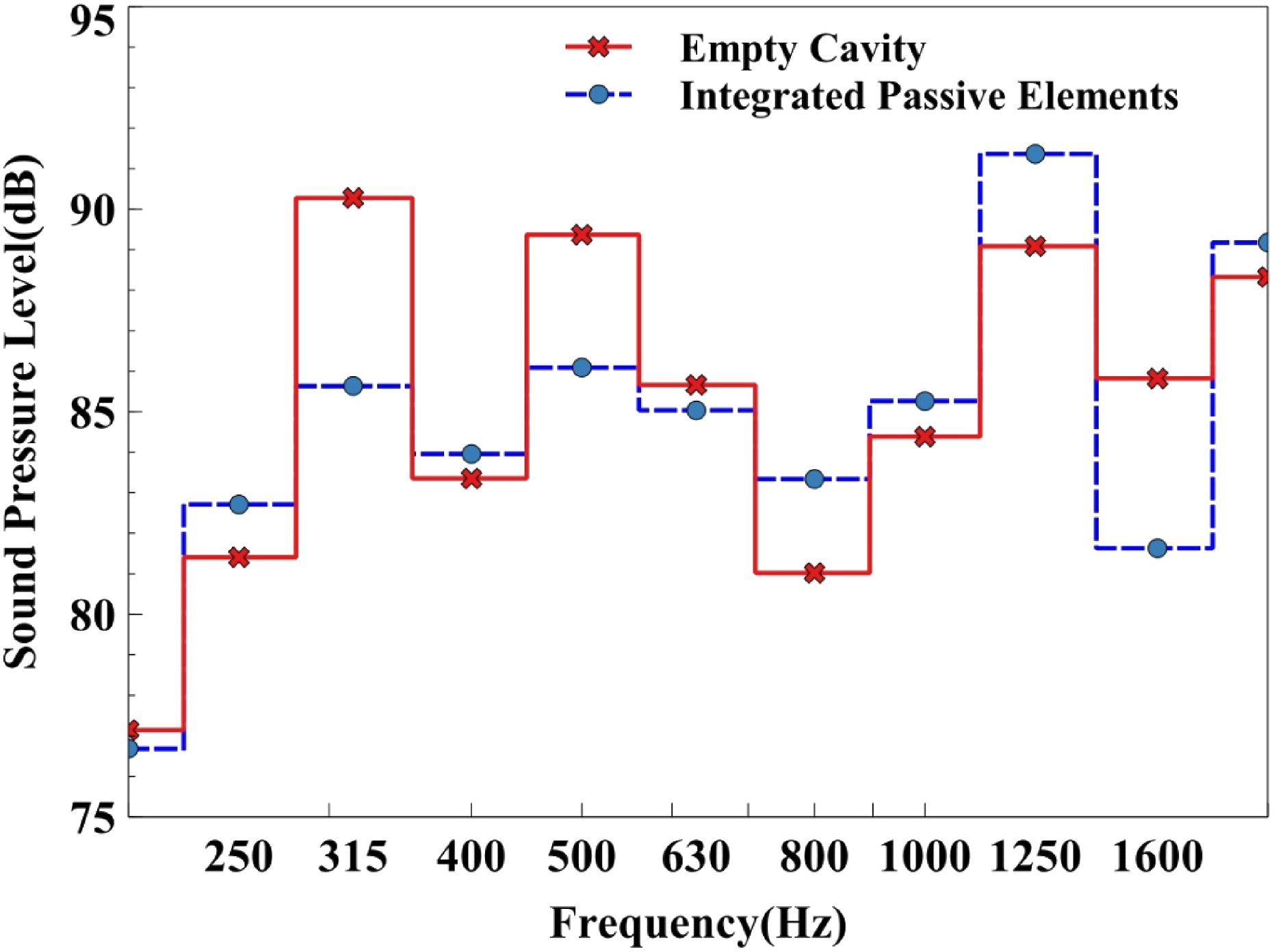
Figure 12 depicts the comparison of experimental OSPL results for empty cavity and cavity coupled with integrated passive elements. The measurements are taken at different locations to obtain OSPL in the chosen frequency range of 200 Hz–1000 Hz. The coupled-cavity results indicate that noise suppression occurs not only in the dominant region but also in the wide range of frequencies. Implementation of 40 mm thickness IPE acts as a broadband absorber, and the results confirm the noise suppression in primary dominant frequencies. Further OSPL of the empty cavity and IPE coupled-cavity results are plotted in the 1/3
rd
octave band depicted in Figure 13. Overall, 4–6 dB noise was noticed in 1/3
rd
octave frequency band. Experimental OSPL results of empty cavity and cavity coupled with IPE. Comparison of experimental OSPL of empty cavity and IPE in 1/3 octave band.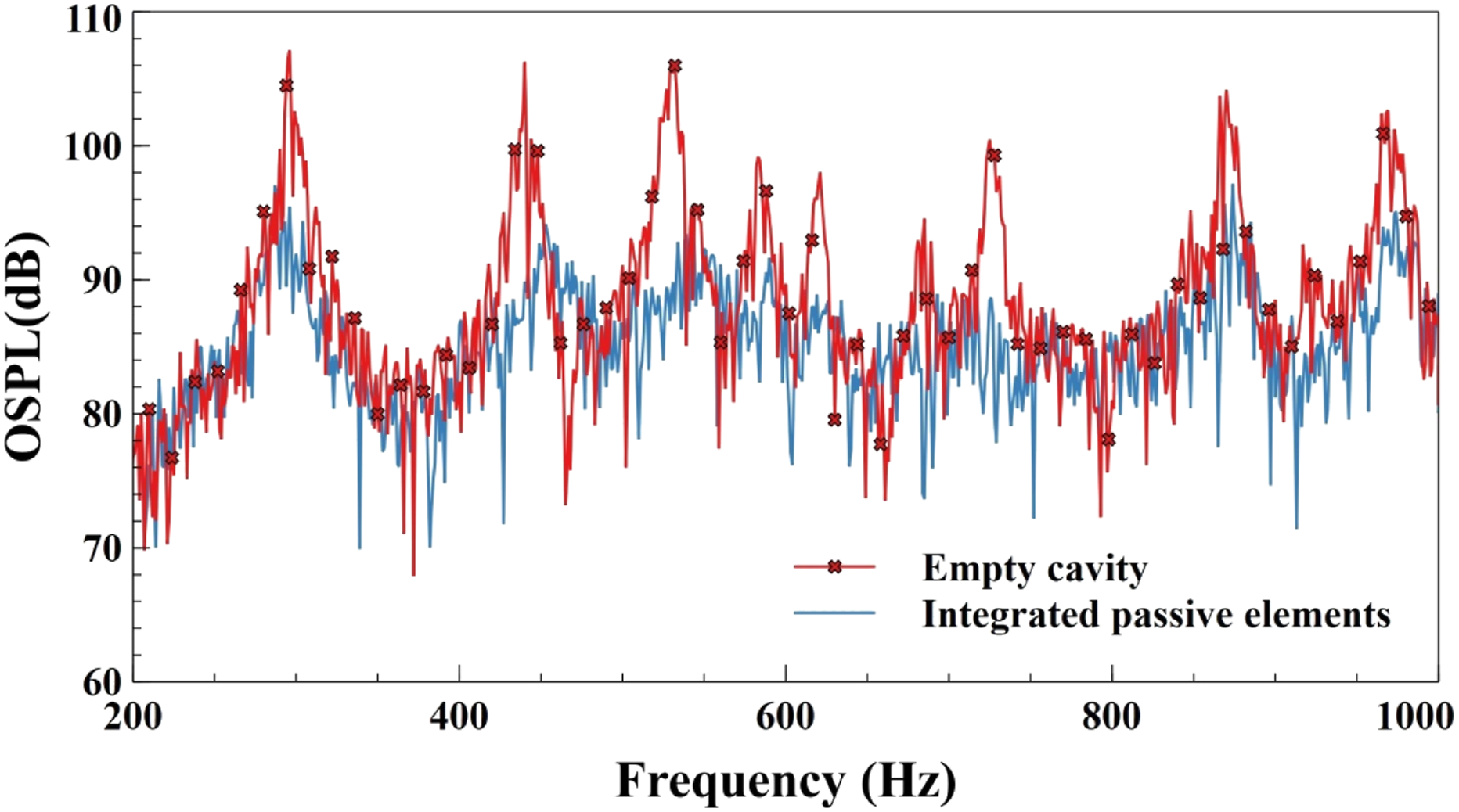
Conclusion
In this study, the potential of IPE printed using the FDM technique is tested in the rectangular cavity of dimension Individual characterization of passive elements was performed to tune the HR and MPP in order to suppress the cavity mode frequencies. The proposed 3D-printed integrated passive elements exhibit a wide range of sound absorption and are validated by theoretical results. Additionally, the empty cavity was analyzed numerically, and its results were validated with the experiment. Similarly, in real-time experimental testing, an empty cavity and cavity coupled with an array of IPE are investigated. As a result, OSPL is obtained, and it indicates a 4–6 dB reduction in 1/3
rd
octave frequency band. Thus, the proposed system works well in all dominant frequencies and also acts as a broadband absorber. It is also noted that a minimum of 1% volume fraction of resonator to cavity volume is essential for better noise attenuation in the dominating frequency.
Footnotes
Declaration of Conflicting Interests
The author(s) declared no potential conflicts of interest with respect to the research, authorship, and/or publication of this article.
Funding
The author(s) received no financial support for the research, authorship, and/or publication of this article.