
Abstract
A new method of removing waste chips is proposed by focusing on the key factors affecting the processing quality and efficiency of high energy beams. Firstly, a mathematical model has been established to provide the theoretical basis for the separation of solid–liquid suspension under ultrasonic standing wave. Secondly, the distribution of sound field with and without droplet has been simulated. Thirdly, the deformation and movement of droplets are simulated and tested. It is found that the sound pressure around the droplet is greater than the sound pressure in the droplet, which can promote the separation of droplets and provide theoretical support for the ultrasonic suspension separation of droplet; under the interaction of acoustic radiation force, surface tension, adhesion, and static pressure, the droplet is deformed so that the gas fluid around the droplet is concentrated in the center to achieve droplet separation, and the droplet just as a flat ball with a central sag is stably suspended in the acoustic wave node.
Keywords
Introduction
In internal processing, the processing tool, namely, high energy beam, is directly used in the interior of the material to be processed to change the designated position structure or physical and chemical properties, complete the material microstructure change or performance modification, and realize the hollow microstructure manufacturing.1–8 It is complementary to the traditional “external processing” method and plays a role in combination, which is conducive to breaking through the constraints of traditional design methods and processing technology, solving the problems of slow processing speed, many processing procedures, low product success rate and difficult to realize complex spatial structure in the preparation of three-dimensional hollow microstructure, and has broad application prospects.
However, how to discharge the scraps smoothly is the bottleneck in the development of internal processing technology. Li et al. 9 studied the interaction mechanism between the three-dimensional spiral microchannel femtosecond laser and the material and discussed the influence of waste discharge on the processing quality and efficiency; Hwang et al. 10 studied the processing mechanism of different cross-section shape and aspect ratio assisted by different liquids and the effect of viscosity of auxiliary liquid on chip removal. Li et al. 11 studied the problem of the difficult discharge of EDM deep small hole machining chips and studied the effect of super-hydrophobic surface electrode on the replacement rate of the bottom working fluid under the same process conditions. Ke et al.12,13 studied the dynamic process of chip removal in the low power femtosecond laser processing spiral channel. Through the literature analysis, we can draw the following conclusions: (1) the internal processing is concentrated in the field of transparent materials, and the research on the internal processing of metal materials is less; (2) chip removal is the key factor affecting the processing quality and efficiency, most of the previous research focuses on the liquid assisted chip removal, and there is no systematic report on the ultrasonic assisted chip removal. For ultrasound assistance, it can penetrate nontransparent materials, and it is easy to obtain concentrated sound energy, which is beneficial to the internal processing of metal materials.
Based on this, this article is devoted to the study of the discharge process of molten metal materials under the condition of acoustic suspension. 14 As a prospective study, ultrasonic technology is used to simplify the discharge process into the separation and desorption process of droplets and solids under the condition of acoustic suspension.
Numerical method
Mathematical modeling
The simplified solid–liquid desorption model under the condition of acoustic suspension is shown in Figure 1(a). The droplets on the flat wall are loaded with an ultrasonic standing wave. Under the coupling effect of acoustic flow, the liquid surface shrinks and the boundary is separated, and then the suspension is stable at the standing wave node (Figure 1(b)). The wetting angle of the solid–liquid interface is shown in Figure 1(c), which represents the relationship between the interfacial tension among solid phase boundary, gas phase boundary, and liquid phase boundary; the radius of solid–liquid contact surface is set as λ. Taking the radiating end and the reflection end as the calculation domain, the relevant mathematical model is established as follows: 1. Continuity equation
15
2. Bernoulli equation
16
Solid–liquid desorption model: (a) solid–liquid desorption model; (b) droplet stabilization model in standing wave nodes; (c) schematic diagram of solid–liquid contact surface; and (d) cylindrical coordinate system.
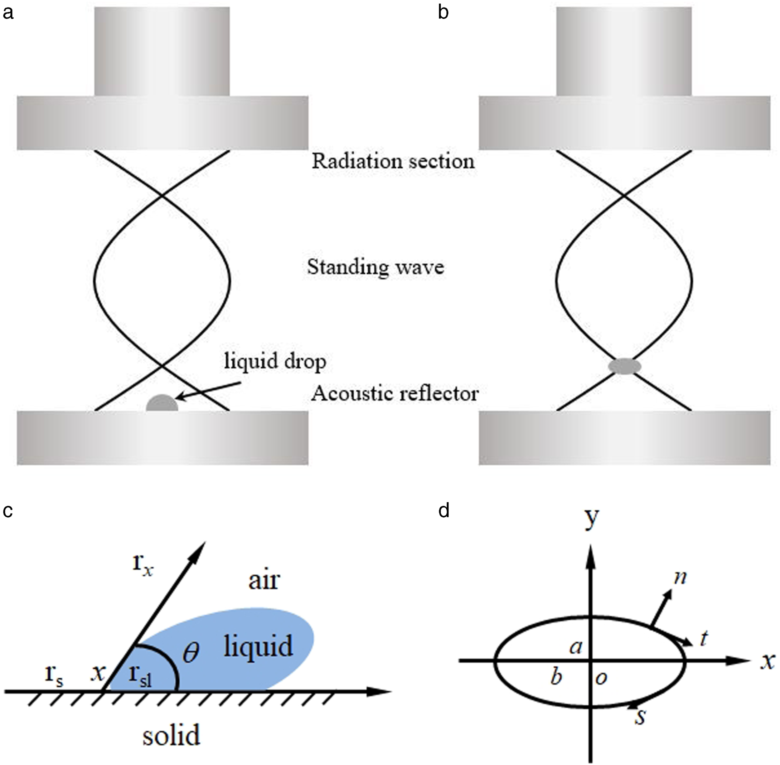


Because the quadratic terms of u and βu are small, the combined equation (2) can be converted into 3. Kinematic equation
16

Considering the motion speed and process of the droplets, the droplets are incompressible, and assuming that the droplets are inviscid and irrotational, the velocity u can be described as a gradient of potential energy Φ
L
:

The kinematic conditions of the droplet surface can be defined by the Bernoulli equation


To simplify the calculation, a cylindrical coordinate system is used, as shown in Figure 1(d), where s is the arc length of the bus along the droplet surface. The characteristic length a0 is defined as the radius of the droplet equivalent sphere, the surface tension produced by the droplet with characteristic pressure p0 being the radius a0, and the characteristic velocity potential Φ0 is the velocity potential amplitude of the incident sound field; then, the mathematical description of the droplet surface evolution can be expressed as the velocity field amplitude of the incident sound field


So far, the droplet surface boundary integral equation can be obtained and solved by the boundary element method

Computing method
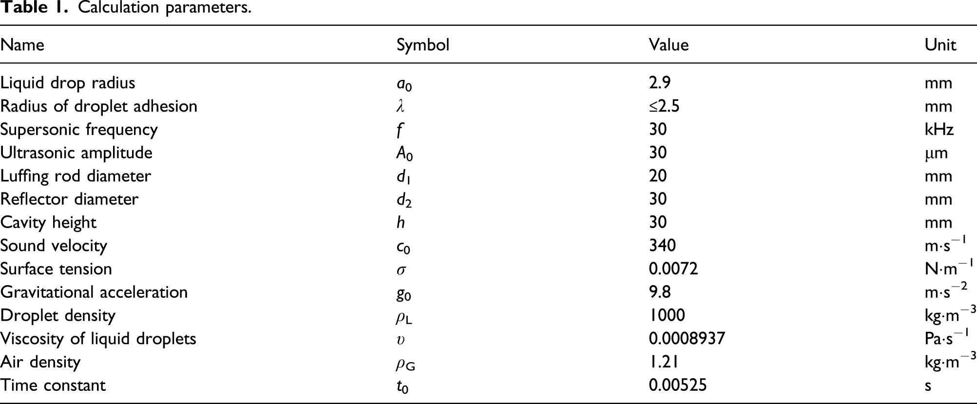
Equations (10)–(12) is a first-order differential equation describing the motion of the droplet surface over time. Assuming that the initial condition droplet surface velocity is zero, the fourth-order Runge–Kutta method is used to solve the problem and record the droplet surface shape and velocity. To speed up the calculation process and stability, firstly, the sound pressure distribution is simulated as the initial condition, and the droplet shape and motion state under the ultrasonic standing wave are simulated by two-phase flow-moving grid technology. The computational domain of COMSOL Multiphysics simulation software is shown in Figure 2 and the calculation parameters are shown in Table 1. Computational domain and boundary conditions. Calculation parameters.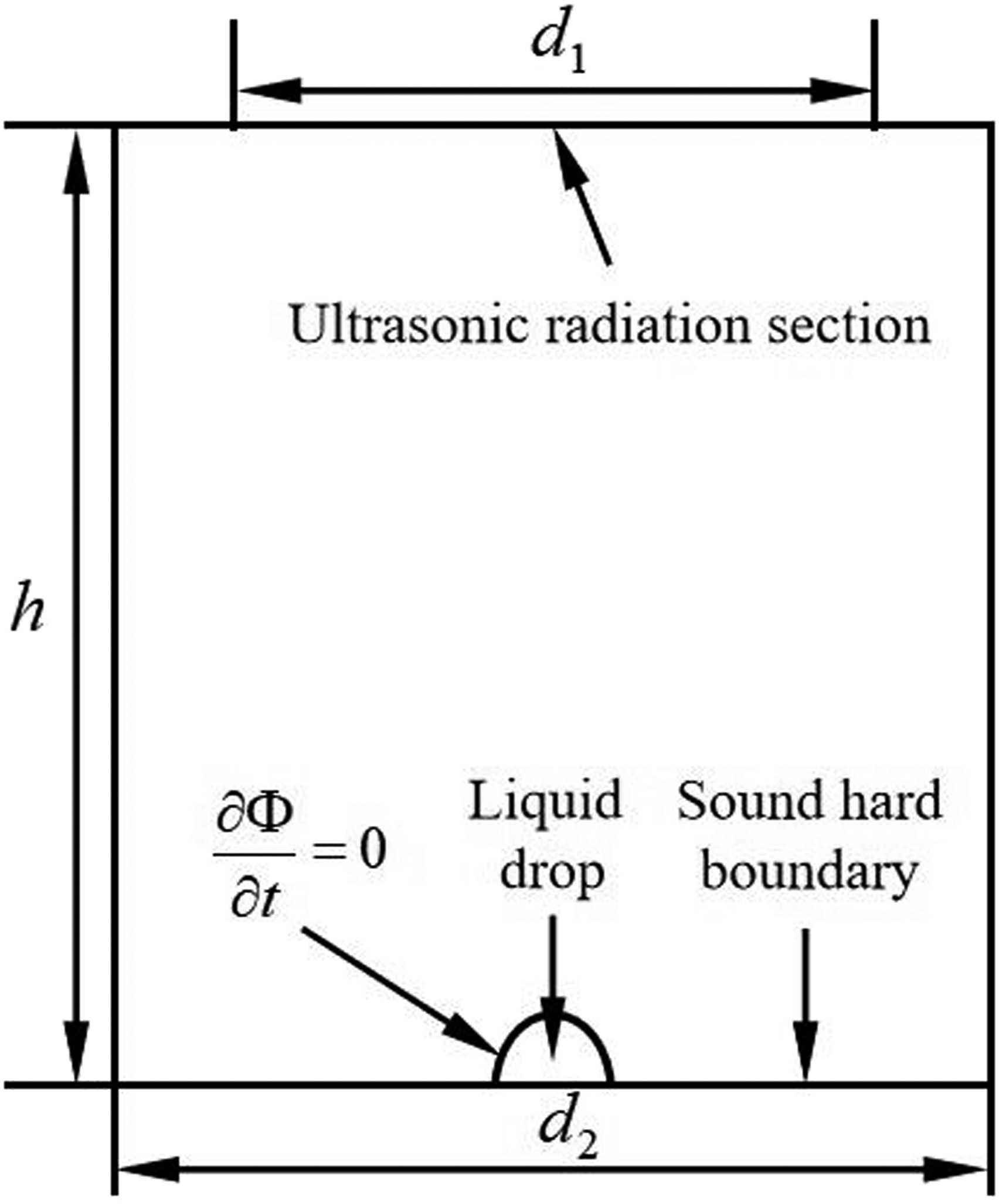
The third-order B-spline difference function is used to calculate the surface tension pressure and hydrostatic pressure. Meanwhile, the boundary element method is used to solve the sound scattering problem to obtain the sound field velocity potential on the surface of the droplets, and then, the objective function is obtained.
Experimental methods
Experimental setup
According to the corresponding simplified model and theoretical analysis, a droplet suspension separation test rig (Figure 3) is built.
19
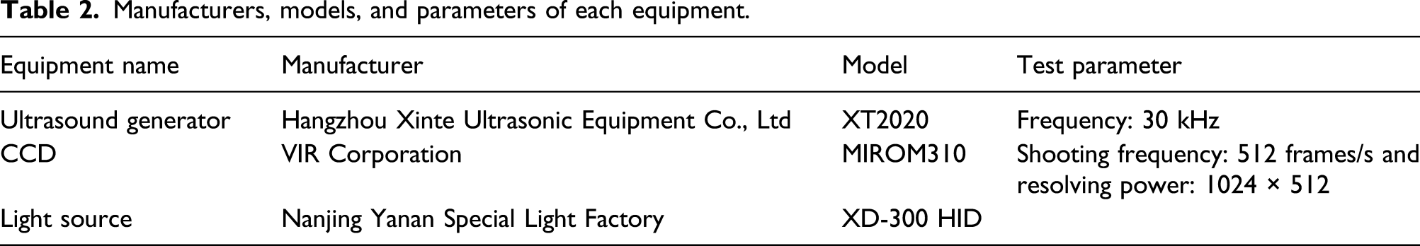
The main equipment and instruments include ultrasound generator, ultrasonic radiation section, acoustic reflector, CCD, and light source and accessory equipment such as motion control equipment. The manufacturers and parameters of relevant equipment are shown in Table 2. System diagram of droplet suspension separation test. Manufacturers, models, and parameters of each equipment.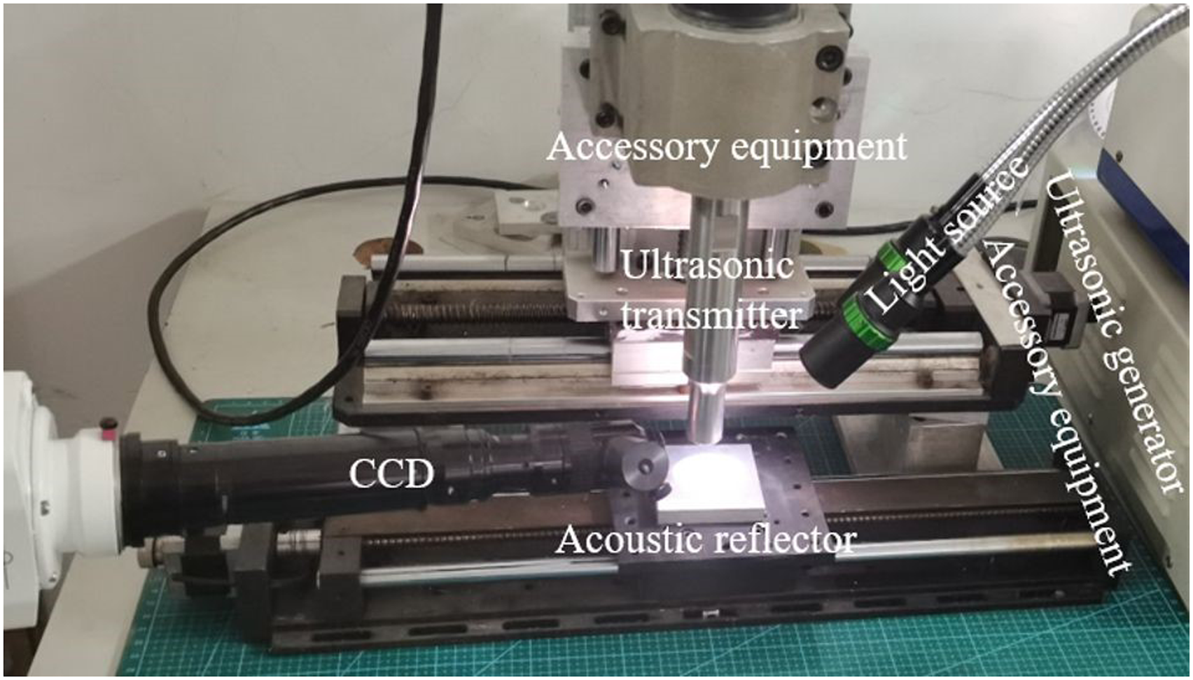
Experimental observation
The shooting light source is used to illuminate the entire flow field and sound field, and the CCD is used to shoot the desorption process. The light source used is white light, the shooting frequency is 512 frames/s, and the resolution is 1024 × 512. Adding red ink to the droplets is more conducive to the observation of the changes in the shape of the droplets. At the same time, it ensures that the solid reflection end, the ultrasonic reflection end, and the liquid drop are on the same central axis.
Results and discussion
Distribution of sound pressure in standing wave field
Sound pressure distribution is shown in Figure 4. When there are no droplets (Figure 4(a)), the sound pressure is basically axially symmetrical and the isobaric surface is a series of closed curved surfaces with regular shapes.
20
Although the sound pressure distribution with droplets (Figure 4(b)) is axially symmetrical, the sound pressure distribution near the reflecting end and radiating end is obviously different from that without droplets (Figure 4(a)). The shape of the isobaric surface changes and some isobaric surfaces are no longer complete.
21
It is totally enclosed in the calculation domain; the sound pressure at the near-reflecting end decreases by 30% compared with that without droplets; the isobaric surface at the reflecting end is divided into two hemispheres symmetrically left and right, which is significantly different from the isobaric surface without droplets (Figure 4(a)). From the distribution of sound pressure on droplets A, B, and C in Figure 4(b), it can be seen that the sound pressure at A and B is higher than that at C inside the droplet, similar to the conclusion of Hong.
16
This mechanical behavior can cause the droplet to shrink and separate, which provides theoretical support for the reliability of ultrasonic suspension separation of droplets. Simulation results of total sound pressure field distribution: (a) no droplets and (b) with droplets.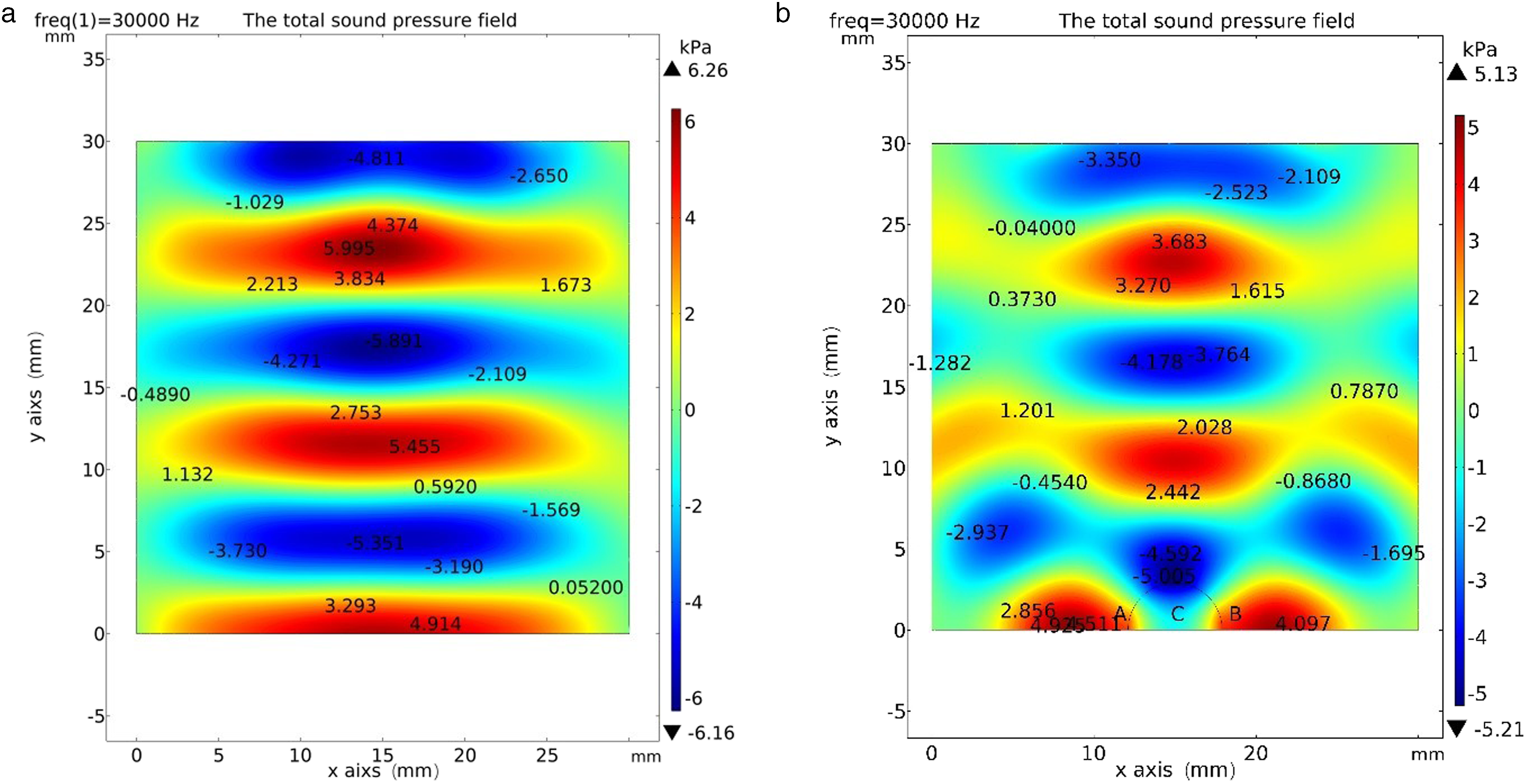
Sound pressure and streamline distribution along longitudinal and transverse axes of droplets
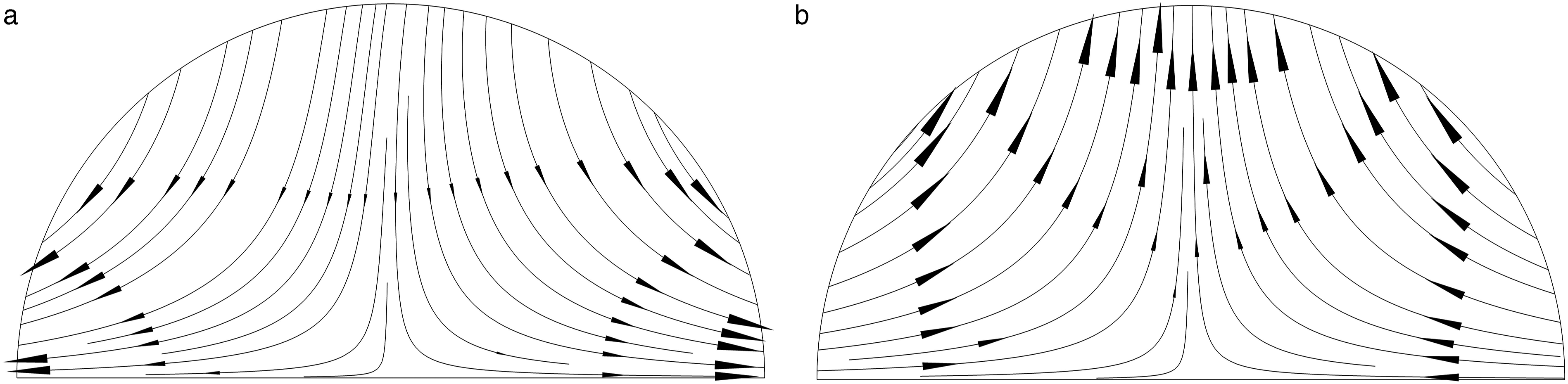
In order to better reflect the sound pressure and streamline distribution on the surface and inside of the droplet, a certain area (12 ≤ x ≤ 18 mm, 0 ≤ y ≤ 3 mm) as shown in Figure 4(b) is selected as the research object. And because this model uses a two-dimensional model, it is necessary to use the two-dimensional cross-section method (x = 15, y = 0; x = 15, y = 3) to process the internal sound pressure of the droplet to obtain data. The simulation results are shown in Figures 5 and 6. Variations of sound pressure along the longitudinal and transverse of droplet: (a) sound pressure of droplet surface along the Y-axis direction, (b) sound pressure inside the droplet along x = 15 mm, and (c) sound pressure along the direction y = 0 mm. Streamline distributions along longitudinal axis and transverse direction of the droplets at t = 5 ms and 10 ms: (a) t = 5 ms and (b) t = 10 ms.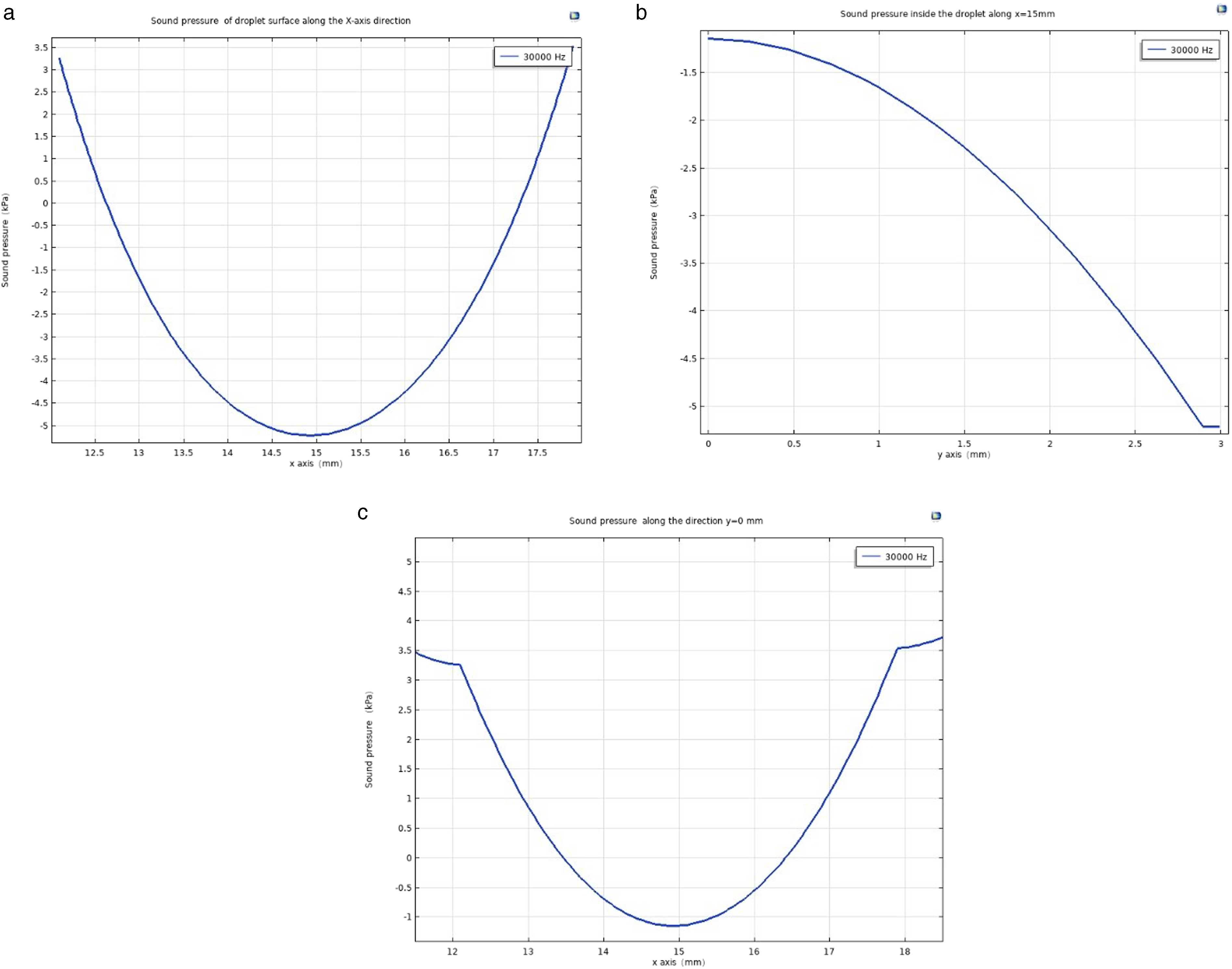
As can be seen from Figure 5(a), the sound pressure on the droplet surface is symmetrically distributed relative to x = 15 mm. The negative value of the sound pressure at the center of the droplet surface gradually increases in the positive value of the sound pressure on both sides of the droplet. The sound pressure curve of the droplet surface shows a parabola shape with opening upward, and the lowest value reaches −5.21 kPa at the highest point of the droplet surface. As can be seen from Figure 5(b), along the direction x = 15 mm, the sound pressure inside the droplet is always negative. With the increase of droplet height, the sound pressure decreases gradually, but the decreasing speed increases gradually, and the sound pressure reaches the minimum value at the liquid level. In Figure 5(c), the change trend of the sound pressure on the contact surface between droplets and the reflection end is consistent with that in Figure 5(a), and the lowest value is −1.142 kPa at the most central position where droplets contact with solids.
As can be seen from Figure 6(a), when t = 5 ms, the droplets rotate clockwise and anticlockwise on the left and right sides, respectively, under the action of sound pressure, and the flow direction extends; when t = 10 ms, the flow lines are counterclockwise and clockwise on the left and right sides, respectively, and the flow direction is upward from the boundary to the center.
Through analysis, it can be seen that the sound pressure on both sides of the droplet is positive, while the sound pressure inside the droplet is negative, which is equivalent to a resultant force to push the droplet upward. At the same time, under the action of radial inward sound pressure, the whole droplet has a tendency to shrink inward, which reduces the contact area between the droplet and the reflection end, and is more conducive to the droplet to leave the solid reflection end and achieve a stable suspension state.
Suspension separation of adhesive droplets under ultrasound standing wave field
In order to accurately describe the droplet shape change and movement process, the numerical simulation and test results of each state evolution in one cycle (0.8 s) are shown in Figure 7. At t = 0 s, the droplet adheres to the surface of aluminum reflecting end under surface tension and adhesion force, and at this time, ultrasonic wave is applied. When t = 0.2–0.3 s, the droplet starts to shrink and deform under the action of sound radiation pressure; the wetting angle gradually increases and the deformation is obvious; when t = 0.45–0.5 s, the coupling of sound radiation force, surface tension, adhesion force, and static pressure drives the fluid on both sides of the droplet shaft section to gather centrally; the wetting angle is greater than 90°, the wetting tension is small, and the droplet is lengthened lengthwise in mushroom shape, showing a separation tendency. When t = 0.75–0.8 s, the droplet is suspended stably at the standing wave joint and deformed under the action of sound pressure, becoming flat spherical and further flattened. The central part of the upper and lower surfaces changes from convex to concave, which is consistent with the conclusion of Xie
22
; when t > 0.8 s, the droplet atomizes at the standing wave joint. Droplet suspension separation process: (a) t = 0 s, (b) t = 0 s, (c) t = 0.2 s, (d) t = 0.3 s, (e) t = 0.45 s, (f) t = 0.5 s, (g) t = 0.75 s, and (h) t = 0.8 s.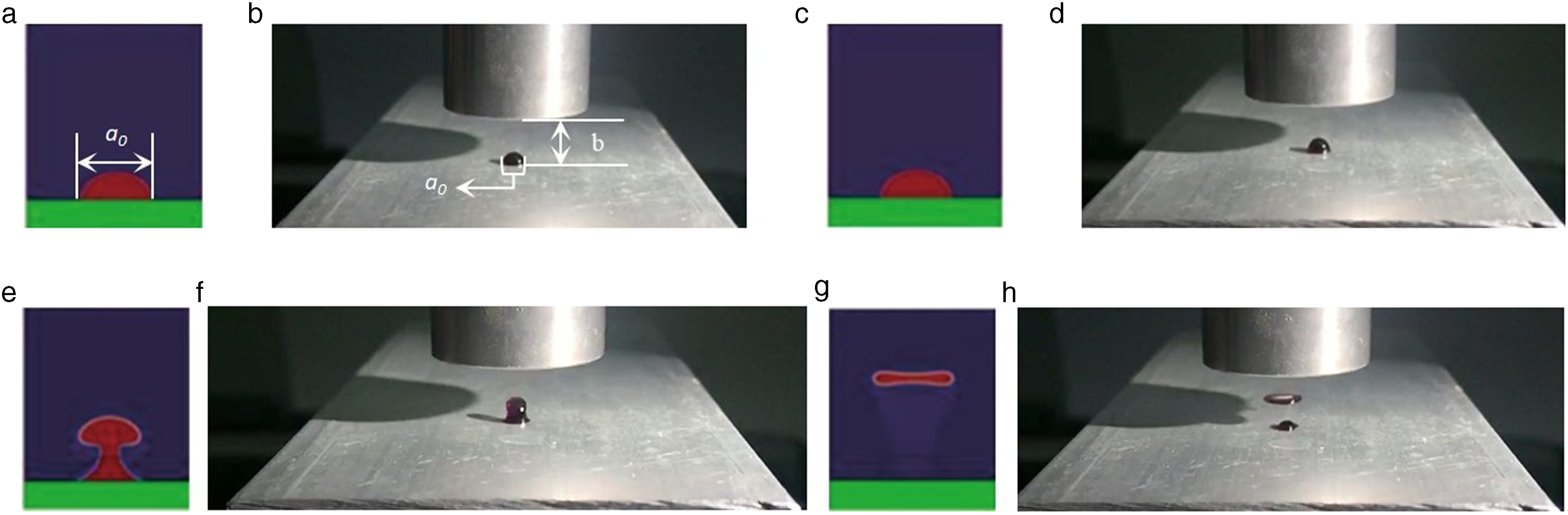
Conclusions
Through the research in this study, the following conclusions can be drawn: The sound pressure on both sides of the droplet profile is higher than the sound pressure inside the droplet, which can cause the droplet to shrink and separate. The deformation and movement process of droplets indicate that under the coupling action of sound radiation force, surface tension, adhesion force, and static pressure, the deformation of droplets drives the fluid on both sides of the axial profile of droplets to gather toward the center, thus achieving separation and suspending stably at the joint with flat spherical shape in the central depression. The sound pressure at the wave node is different from that at the reflecting end, and the droplets are atomized after reaching the wave node. Under the condition of ultrasonic suspension, it contributes to discharge the dandruff.
Footnotes
Declaration of conflicting interests
The author(s) declared no potential conflicts of interest with respect to the research, authorship, and/or publication of this article.
Funding
The author(s) disclosed receipt of the following financial support for the research, authorship, and/or publication of this article: This work is supported by the National Natural Science Foundation of China (51775154).