
Abstract
By studying dynamic characteristics of the leaf spring system, a new elastic component is designed to reduce the working load and to a certain extent to ensure the linearity as well as increase the amplitude in the vertical and horizontal directions in vibration screen. The modal parameters, amplitudes, and amplification factors of the leaf spring system are studied by simulation and experiment. The modal results show that the leaf spring system vibrates in horizontal and vertical directions in first and second mode shapes, respectively. It is conducive to loosening and moving the particles on the vibration screen. In addition, it is found that the maximum amplitude and amplification factor in the horizontal direction appear at 300 r/min (5 Hz) while those in the vertical direction appear at 480 r/min (8 Hz), which are higher than those in the disc spring system. Moreover, the amplitude of the leaf spring system increases proportionally with the increase of exciting force while the amplification factors are basically the same under different exciting forces, indicating the good linearity of the leaf spring system. Furthermore, the minimum exciting force occurs in the leaf spring system under the same amplitude by comparing the exciting force among different elastic components. The above works can provide guidance for the industrial production in vibration screen.
Introduction
Vibrating screen is a kind of common large-scale mechanical equipment used for screening or size measurement of rock and ore in mining engineering. 1 At present, there are many kinds of vibrating screens in industry such as linear vibration screen, 2 resonance screen, 3 circular vibration screen, 4 and banana screen. 5 Among them, due to simple structure, stable work, and easy control, traditional circle and linear vibration screen are extensively used in production. However, the vibration amplitude cannot be amplified by resonance principle in these screens. Hence, the large external excitation is needed in the traditional circle and linear vibration screen, 6 which is easy to lead to fatigue failure of vibration screen components. Although the resonance screen can obtain lager amplitude by resonance principle, the nonlinear spring is adopted in screen.7,8 It contributes to the unstable working state and poor vibration linearity.9,10 Therefore, it is urgent to find a new type of vibration screen in mineral engineering.
In view of the common shortcomings of the traditional vibrating screen, a new disc spring elastic component was designed in previous research, 11 and it has been used in circle vibration screen. With the vertical stiffness increasing in the device, the amplitude is amplified by resonance principle in the main vibration direction. The larger amplitude is obtained by less exciting force. 12 It not only saves energy but also improves the service life of the vibrating screen.13–15 Meanwhile, this new elastic component has excellent mechanical property and stable working state. To a certain extent, the major drawbacks 16 of traditional vibration screen are avoided in the disc spring vibration screen.
Although the disc spring vibration screen has many advantages mentioned above, there are some other problems in this system. The vertical stiffness of the disc spring system is far greater than horizontal stiffness, 17 which is impossible to resonate in vertical and horizontal directions at the same or close frequency. In addition, due to the influence of the structural characteristics of the disc spring, 18 the amplitude and amplification factor is small in the horizontal direction. However, the motion of particles on the screen surface can be increased by properly improving the amplitude in the horizontal direction, 19 which is more conducive to segregation of particles in the screening process.20,21 Furthermore, from the perspective of engineering projects, high cost of disc spring will greatly increase the total price of vibration screen. 22 It brings challenges to mass production of disc spring vibration screen.
Similar to disc spring, leaf spring is also an excellent elastic element with the advantages of good reliability, simple structure, short manufacturing process, and low cost. 23 Nowadays, the research and application of leaf spring is growing mature.24,25 The mechanical properties of the leaf spring system have been analyzed in many applications. 26 However, the application of the leaf spring system as the main vibration element in vibration screen has rarely been reported. Moreover, the dynamic characteristics of the leaf spring system in vibration screen have not been researched.
In order to obtain a relatively large amplification factor in the horizontal direction as well as in vertical direction, a new leaf spring elastic component was designed in this study. The natural frequency and mode shapes of the leaf spring system are obtained by the modal test in simulation and experiment. Then, the amplitudes and amplification factors of the leaf spring system under different working frequency are investigated. Furthermore, the influence of exciting forces on amplitudes and amplification factors is also studied. Eventually, the dynamic characteristics in the disc spring system and leaf spring system under same amplitude are compared.
Method and methodology
Object description and mechanics analysis
The elastic vibration element is the important component of vibration screen. The experimental picture and diagrammatic sketch of the leaf spring system is shown in Figure 1. The leaf spring system consists of three parts: the left and right leaf springs, lower leaf spring, and the center mass system. The left and right springs are fixed on the left and right trapezoidal supports, respectively. The lower leaf spring and two trapezoidal supports are fixed on the workbench. Meanwhile, three leaf springs are connected with the middle mass block by bolts. The thickness of left and right leaf springs is 4 mm while that of lower leaf spring is 5 mm. And the size and mass of the left and right leaf spring are the same. The total mass of the mass block and connecting board is 426.15 kg. Leaf spring system: (a) experimental picture; (b) diagrammatic sketch.
Linear analysis
It can be seen from Figure 1(b) that the external excitation is provided by the rotation of the eccentric block. Based on the dynamic principle,
27
equation (1) shows the vibration equations of the leaf spring system

In equation (1), the total mass of the three leaf springs and mass block is denoted by m while that of the eccentric block is m0. The damping of the leaf spring system in X and Y directions are C
x
and C
y
, respectively. K
y
and K
x
represent the stiffness of the leaf spring system in X and Y directions. The damping and stiffness of the left leaf spring are C1 and K1 while those of the lower leaf spring are C2 and K2, respectively. The damping and stiffness in the X direction are mainly produced by the left and right leaf spring while those in the Y direction are mainly produced by the lower leaf spring. The system damping C
x
and C
y
in X and Y directions can be expressed as equation (2), and the system stiffness K
x
and K
y
in X and Y directions are shown in equation (3)


Equation (4) shows the centrifugal force of the leaf spring system along X and Y directions. The rotational angular velocity and eccentricity of the eccentric block are ω and r, respectively

Equation (5) is obtained by substituting equations (2)–(4) into equation (1), which shows the horizontal, vertical, and shaking vibration equations of the system
28
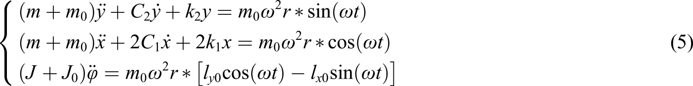
Rotational inertias of the leaf spring system and eccentric mass are J and J0. lx0 and ly0 are the projection distance on X and Y axes between centroid of the leaf spring system and centroid of the eccentric block.
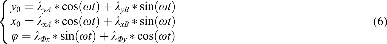
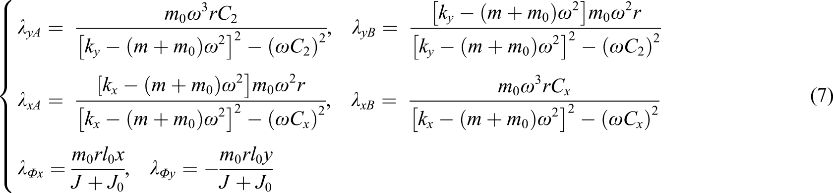
The kinematical equations of the leaf spring system at any position are shown in the following equation

Nonlinear analysis
In general, the movement of the leaf spring system in certain amplitude can be regarded as a linear vibration process. However, in rare cases, there are still some nonlinear vibrations in the leaf spring system. Here, the nonlinear vibration is discussed briefly in the leaf spring system.
Due to the variation of the stiffness and damping in the movement of the leaf spring system, there are damping force and elastic force with nonlinear characteristics in the system. At present, the homotopy perturbation method30–32 is popular for solving nonlinear oscillator, which does not need ε as a small parameter33,34 and can effectively solve the high-order approximate solution. 35 Meanwhile, frequency–amplitude relationship is solved in nonlinear vibration by He’s frequency formulation.36,37 All of the above methods contribute to the solution of nonlinear.
However, the leaf spring system is a standard nonlinear oscillator under sinusoidal force. Therefore, the nonlinear standard form equations of the leaf spring system can be solved directly by the function expansion method
38
as shown in the following equation

As the working frequency of the leaf spring system is basically consistent with its natural frequency, the resonance case of the nonlinear vibration system is only discussed in this work.
The natural frequency

Bringing equation (10) into equation (9), it can get equation (11)

The solution of equation (11) can be regarded as equation (12)


Nonlinear vibration equation (9) under sinusoidal force can be transformed into the following equation

According to the progressive approach of the nonlinear vibration theory,
39
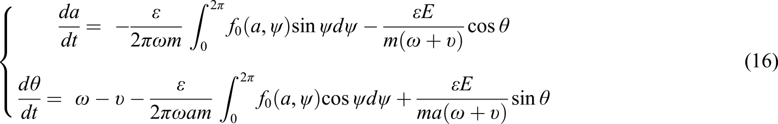
the first approximate solution of equation (14) with the main resonance case (p = 1, q = 1) is shown in the following equation

The a and θ will be determined by the following equation
Modal simulation and experiment
Considering less proportion of nonlinear vibration in the leaf spring system, the subsequent simulation and experiment are based on the linear mechanical analysis of the leaf spring system.
The modal testing method is generally recognized as a powerful method for evaluating the dynamic response of the linear structural systems.40,41 Meanwhile, finite element analysis is extensively used in modal analysis,
42
which can simulate various test schemes as well as time-saving of design and analysis.
43
Figure 2 shows the finite element model meshed by element type Solid 185.
44
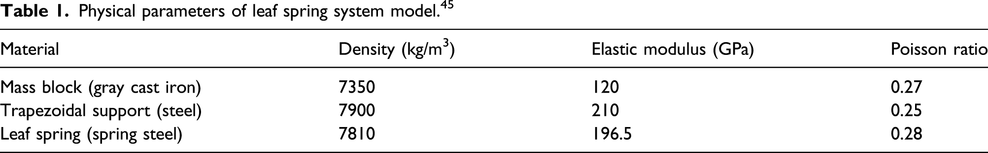
The physical parameters of the model are shown in Table 1. Finite element model of leaf spring system. Physical parameters of leaf spring system model.
45
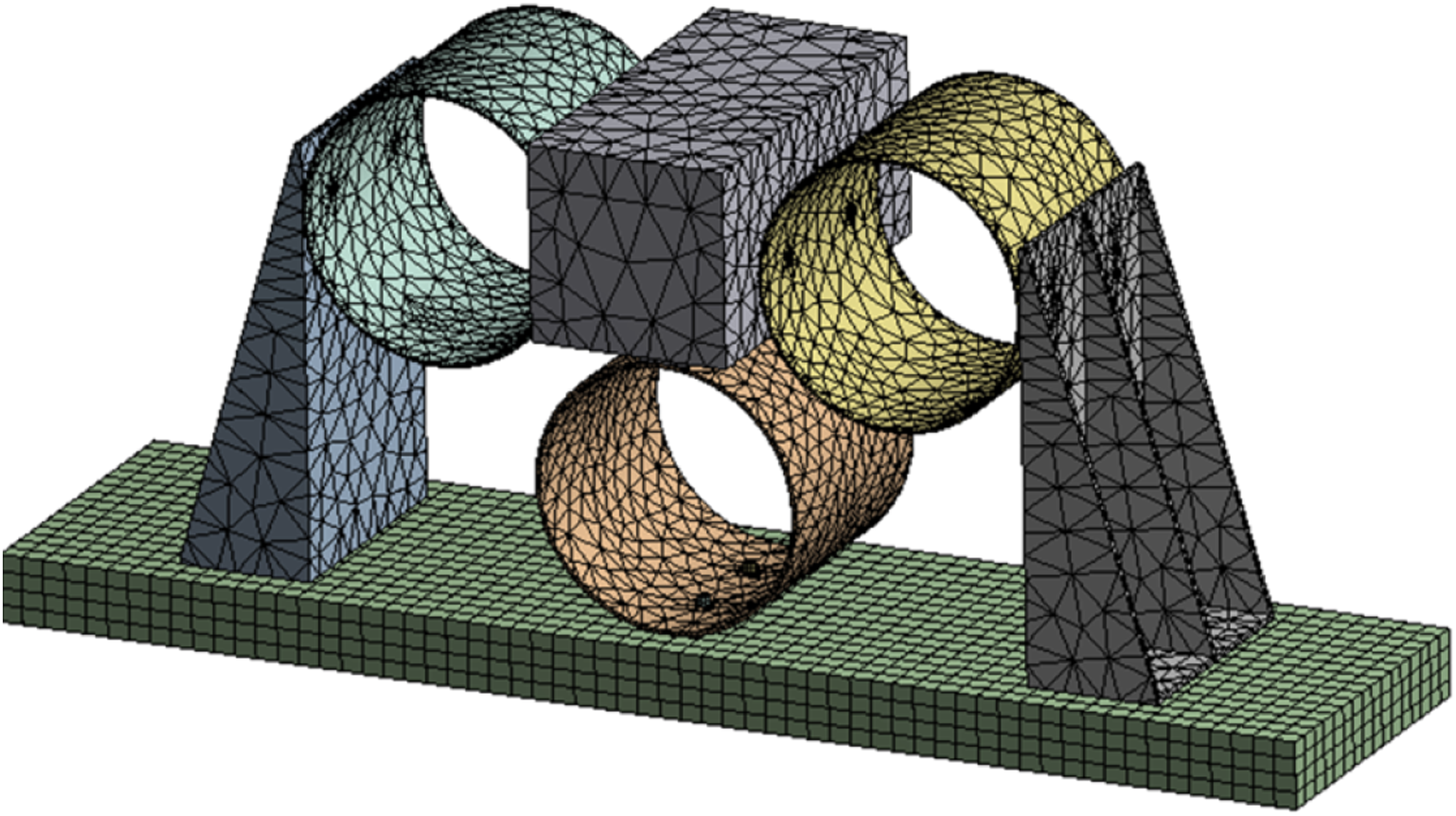
The proper boundary constraints are imposed in the model according to the assembly and fixation of the leaf spring system. All components of the leaf spring system are connected by bolts. There are no other constraint settings except for fixing on the bottom of the workbench. In order to prevent large displacement of the whole system, the weak spring setting is enabled. The solver of the modal module
46
is adopted in simulation after preprocessing of the model. Then, the modal test is carried out after the modal analysis in simulation. The impact test method is adopted in modal experiment. Figure 3(a) shows the experimental equipment and scenarios of the modal test.
47
Impacting excitations are generated in horizontal and vertical directions by heavy hammer. The acceleration signals at different geometric model nodes are gained by six acceleration sensors and analyzed by the data acquisition system of Leuven Measurement & System (LMS).
48
The mode shapes at different natural frequencies are subsequently obtained. Experimental equipment and scenarios: (a) modal test; (b) amplitude test.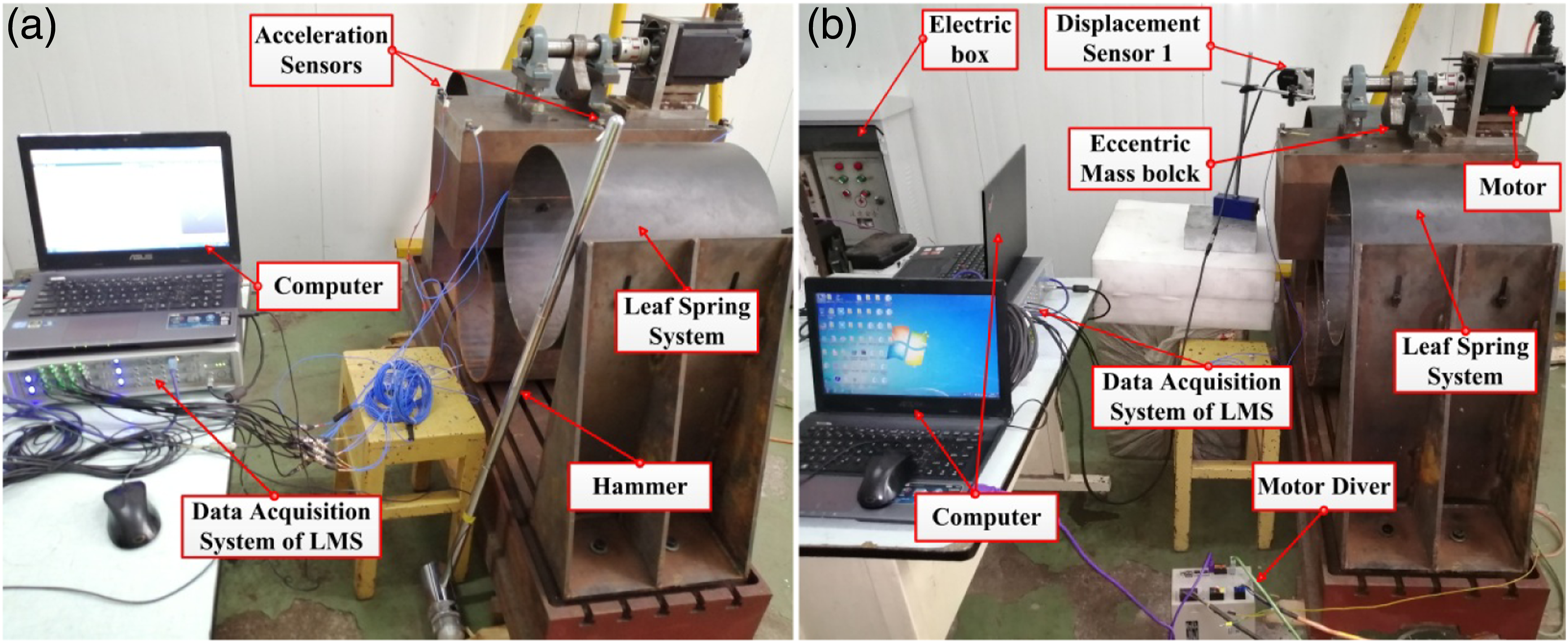
Amplitude simulation and experiment
The purpose of amplitude experiment and simulation is to find the amplitude of the leaf spring system under different working frequencies. The working frequency of the leaf spring system would be adjusted by changing the speed of the driving motor in experiment. The vibrational behavior of the leaf spring system is simulated by the transient analysis module.
49
The amplitude simulation model is same as that in modal simulation. The sinusoidal periodic excitation is applied to the upper surface of the leaf spring system by replacing the excitation load provided by the eccentric block. Equation (17) shows the dynamic force of the leaf spring system
F0 is the excitation force provided by the eccentric block, and F is the real-time dynamic force in the leaf spring system. f denotes the working frequency in the vibration system. And T is time of duration in transient analysis.50,51 m and r represent the mass and eccentricity distance of the eccentric block, respectively. Figure 3(b) shows the experimental scenarios of the amplitude test. The dynamic force is produced by the rotation of the eccentric block. The horizontal and vertical amplitudes of the leaf spring system are measured by two laser displacement sensors. The time history of amplitude is recorded by the data acquisition system of LMS.
Results and discussion
Modal analysis
The first to fourth mode shapes of the leaf spring system are shown in Figure 4(a)–(d), respectively. It can be seen in Figure 4(a) that the leaf spring system sways along the Y direction in first mode shape, which indicates there is obvious tensile and compressive deformation in the left and right leaf springs. As can be seen from Figure 4(b), the system vibrates along the Z direction in second mode shape. Meanwhile, the model shakes along the X direction in third mode shape in Figure 4(c), and the center mass of the system is twisted in fourth mode shape in Figure 4(d). Previous four mode shapes and natural frequencies of leaf spring system in simulation.
To further verify the accuracy of modal simulation, the modal test experiment is carried out. The whole vibration mode shape of the leaf spring system is characterized by change of acceleration signals of measuring points. The square section is used to represent the circular section of leaf spring in mode shape to simplify the measuring process and improve the efficiency. Figure 5 shows the previous four natural frequencies and mode shapes of the leaf spring system in experiment. The white wireframe denotes the static position of the leaf spring system while the colorized wireframe represents the maximum deformation position of the leaf spring system during excitation. It can be seen from Figure 5 that the leaf spring system vibrates along the Y, Z, and X directions in the previous third mode shapes, and the center mass block in the model is twisted in the fourth mode shape, which is the same as that in simulation. Meanwhile, the values of previous four natural frequencies obtained in experiment are slightly lower than that in simulation. This is due to the simplified settings in simulation and energy loss during transmission and test system error in experiment. Previous four mode shapes and natural frequencies of leaf spring system in experiment.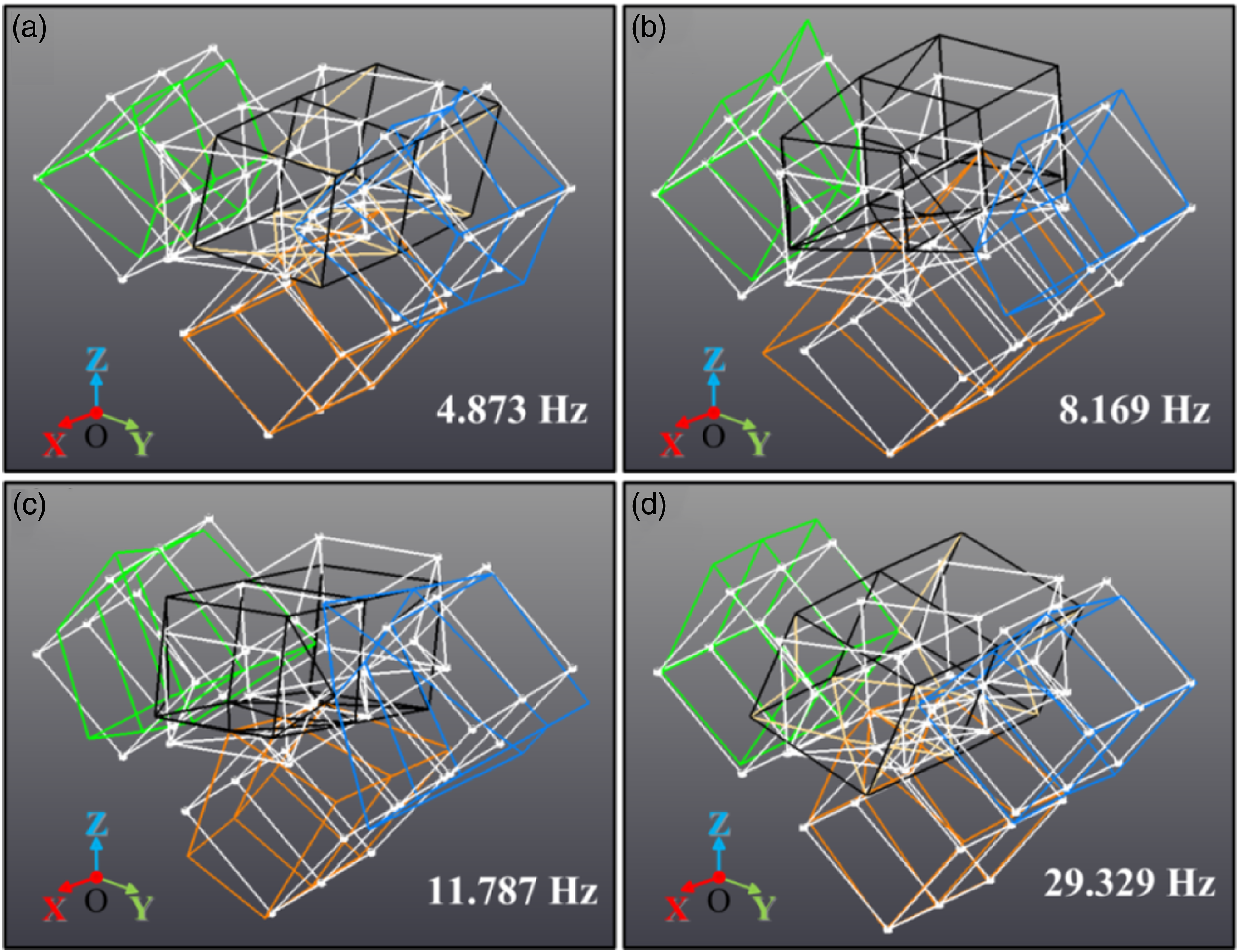
In general, the natural frequency in simulation is basically consistent with that in experiment. Comparing Figures 4 and 5, it can be seen that the mode shapes and frequencies in experiment are in good agreement with those in simulation.
It can be seen in Figures 4 and 5 that the leaf spring system has clear deformation in the horizontal and vertical directions at first and second natural frequency, which are conducive to loosening and moving the particles on the vibration screen. The vibration along the X direction in third mode shape and twist of the center mass block in fourth mode shape are unfavorable for screening. When vibration screen works at these frequencies for long time, the components in vibration screen can be easily damaged, and the screening efficiency is reduced. Therefore, the third and fourth mode shapes should be avoided when screening.
Amplitude and amplification factor analysis
The amplitudes of the leaf spring system in the Z direction under different rotation speeds in simulation are shown in Figure 6. It can be seen from Figure 6 that the whole amplitude waves are stable under different rotation speeds. Meanwhile, the amplitude of the leaf spring system first increases and then decreases with the increase of rotation speed, and the maximum amplitudes of the leaf spring system are 0.23 mm, 1.05 mm, 10.5 mm, and 1.72 mm at the rotation speeds of 180, 360, 540, and 720 r/min, respectively. Amplitude of leaf spring system under four rotation speeds in simulation: (a) 180 r/min; (b) 360 r/min; (c) 540 r/min; (d) 720 r/min.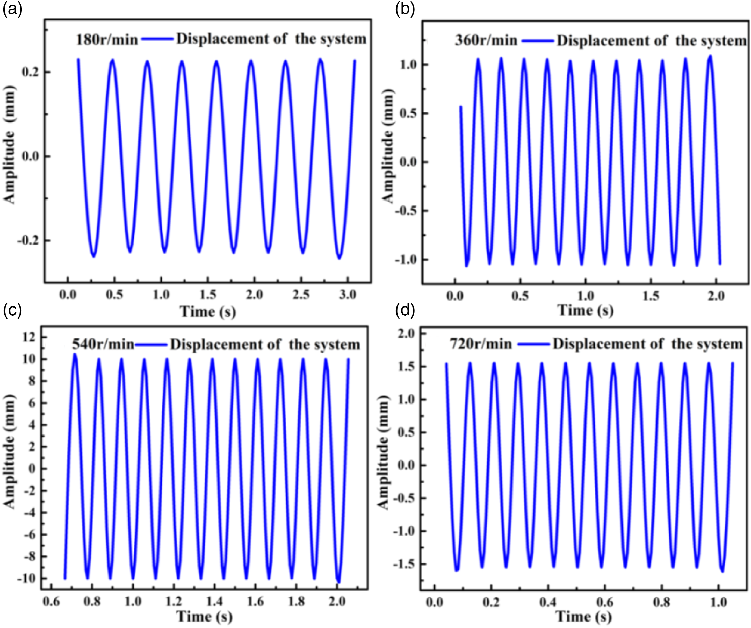
The amplitudes of the leaf spring system in the Z direction under different rotation speeds are further investigated in experiment as shown in Figure 7. The same trend in Figure 7 can be seen as in Figure 6, and the maximum amplitudes of the leaf spring system are 0.17 mm, 0.875 mm, 3.83 mm, and 1.4 mm at the rotation speeds of 180, 360, 540, and 720 r/min, respectively. In general, the maximum amplitudes under different rotation speeds obtained in experiment are slightly lower than those in simulation. Amplitude of leaf spring system under four rotation speeds in experiment: (a) 180 r/min; (b) 360 r/min; (c) 540 r/min; (d) 720 r/min.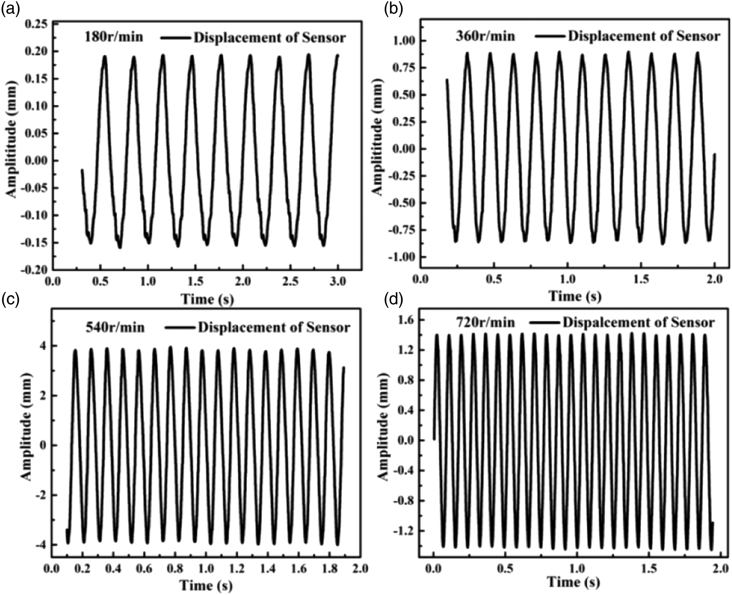
To compare the amplitudes of the leaf spring system in simulation and experiment more specifically, the amplitudes of the leaf spring system in X and Z directions under different rotation speeds are shown in Figure 8. The red and black curves represent the amplitudes of the leaf spring system in the Z direction in simulation and experiment, respectively. Meanwhile, the green and blue curves refer to the amplitudes of the leaf spring system in the X direction in simulation and experiment, respectively. By observing the trend of the curves, it can be found that the amplitudes of the leaf spring system in X and Z directions increase first and then decrease with the increase of rotation speed both in simulation and experiment. The maximum values of amplitude in the X direction in simulation (4.35 mm) and experiment (3.7 mm) appear at 360 r/min (6 Hz) and 300 r/min (5 Hz), respectively. The corresponding frequencies at the maximum amplitude in the X direction are consistent with the first mode frequencies in simulation (6.143 Hz) and experiment (4.873 Hz). Meanwhile, the maximum values of amplitude in simulation (10.02 mm) and experiment (8.83 mm) appear at 540 r/min (9 Hz) and 480 r/min (8 Hz), respectively. The corresponding frequencies at the maximum amplitude in the Z direction are consistent with the second mode frequencies in simulation (9.351 Hz) and experiment (8.169 Hz). Maximum amplitudes under different rotation speed in X and Z directions.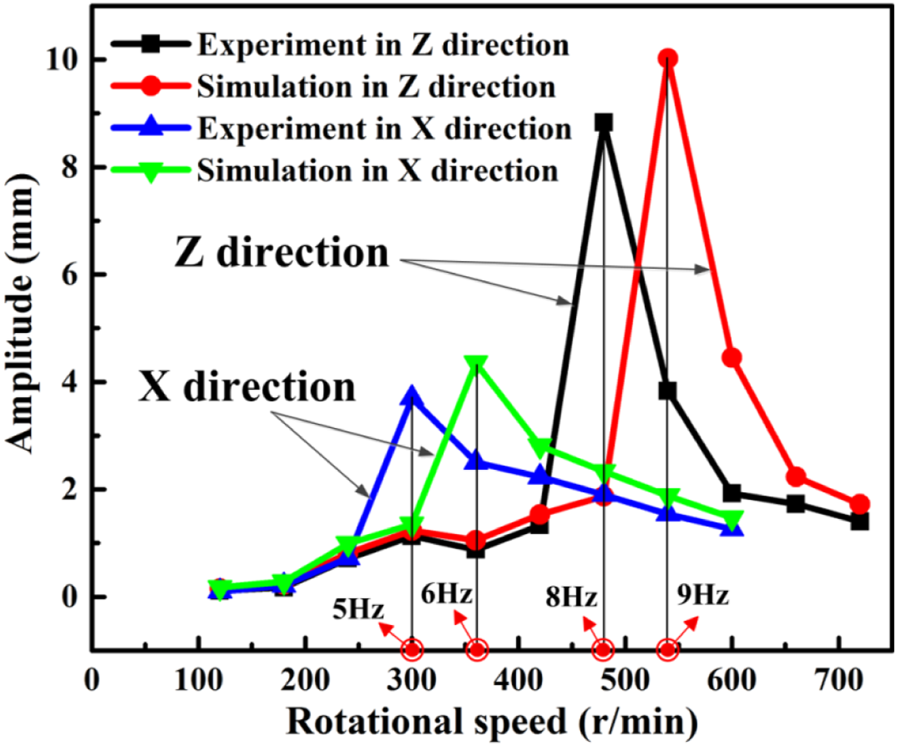
Generally, the trend of the curves in simulation and experiment is consistent, and the values of amplitude in simulation and experiment are very close. However, it can be seen that the amplitude values in simulation are slightly larger than that in experiment. There are two reasons for this phenomenon. First, the natural frequency in simulation is higher than that in experiment. According to formula (9), the higher frequency means larger exciting force, and larger exciting force leads to larger amplitude. Therefore, the amplitude at higher frequency is larger. In addition, experimental interfering factors, such as energy loss during transmission, inefficiency of motor working, and test system error, will lead to less amplitude in experiment than that in simulation.
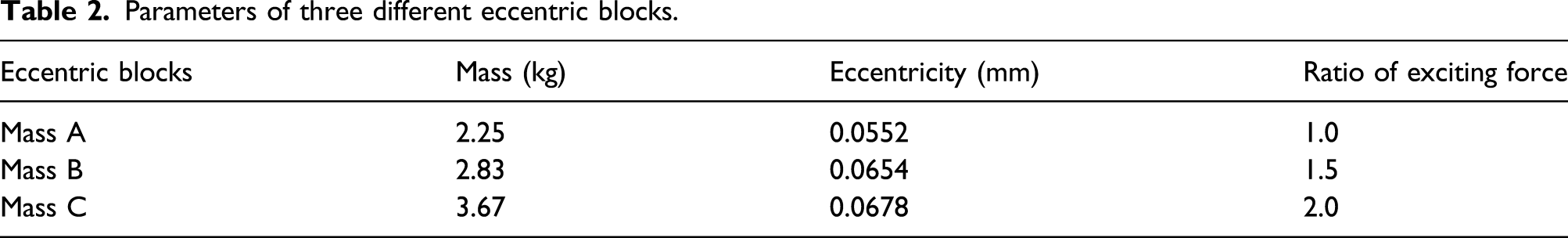
The vibration of the leaf spring system in X and Z directions is beneficial to the screening and moving of particles when screening. To further explore the relationship between the amplitude and exciting force, Figure 9 shows the amplitude curves in X and Z directions under different exciting forces in experiment. By changing the mass and eccentricity in eccentric blocks, the external excitations are adjusted. Three different shapes of eccentric mass A, B, and C are shown in upper right corner in Figure 9. Table 2 shows the parameters of three eccentric blocks. The ratios of exciting force produced by mass A, B, and C are 1, 1.5, and 2, respectively. It can be seen from Figure 9 that the amplitude curve in X and Z directions presents the similar trend of rising and falling. The maximum amplitudes of the leaf spring system in the X direction all appear at 5 Hz under different exciting forces, which indicate the frequency at the maximum amplitude has good stability as the exciting force changes. And with the increase of the exciting force, the amplitude of the leaf spring system increases proportionally. Similarly, the maximum amplitudes of the leaf spring system in the Z direction all appear at 8 Hz under different exciting forces, and the amplitude of the leaf spring system increases as the exciting force increases. Amplitudes of leaf spring system under different exciting forces. Parameters of three different eccentric blocks.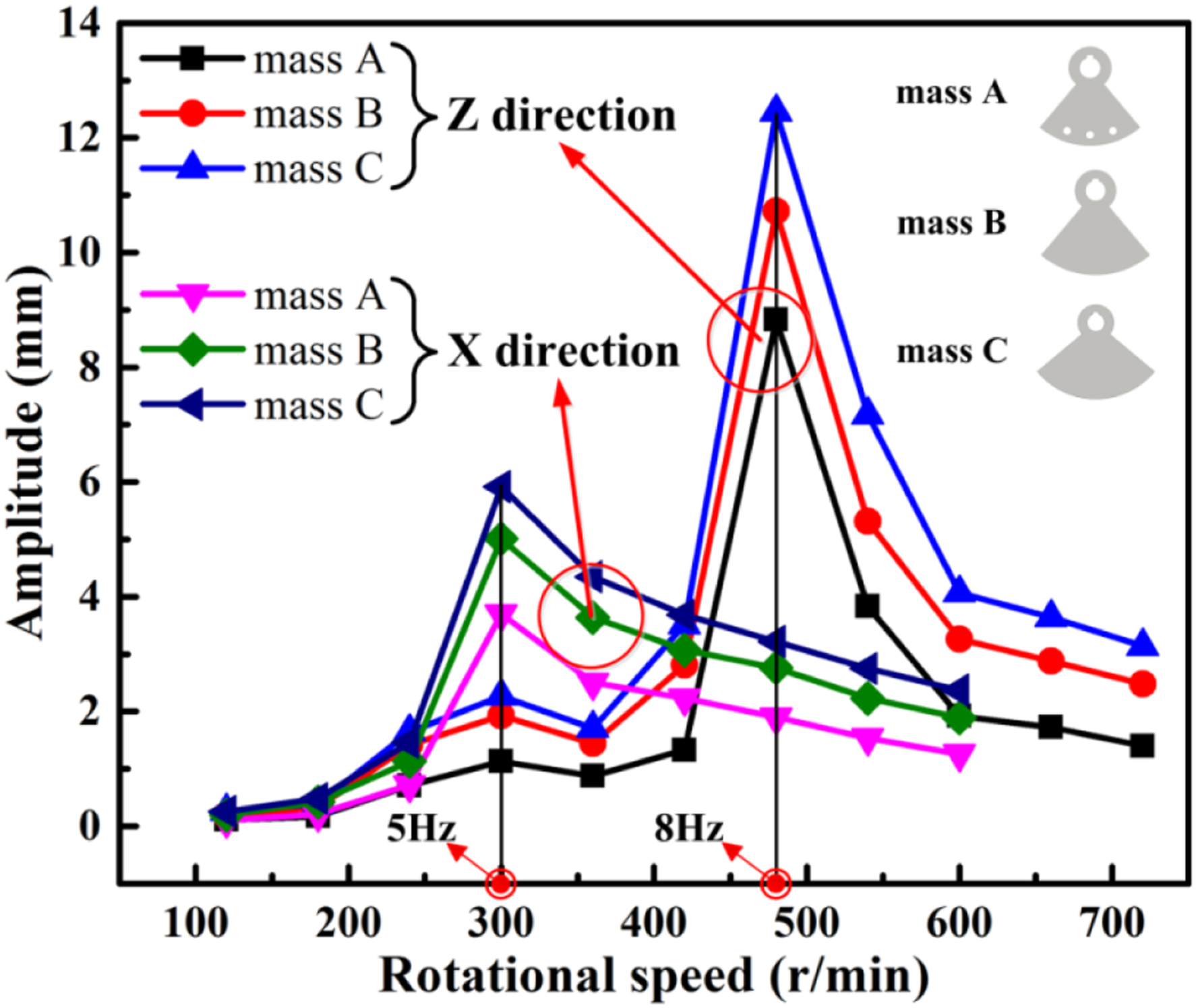
The vibration amplification factor is the ratio of output variation to input variation.
52
The larger amplification factor means the greater influence of input variables on output variables. Therefore, the amplification factor is an important index to evaluate the quality of the elastic system. The relationship among the amplitude X, static displacement A, and amplification factor 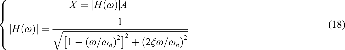
The amplification factors of the leaf spring system in X and Z directions under three different exciting forces are researched as shown in Figure 10. Amplification factor of leaf spring system under different eccentric masses.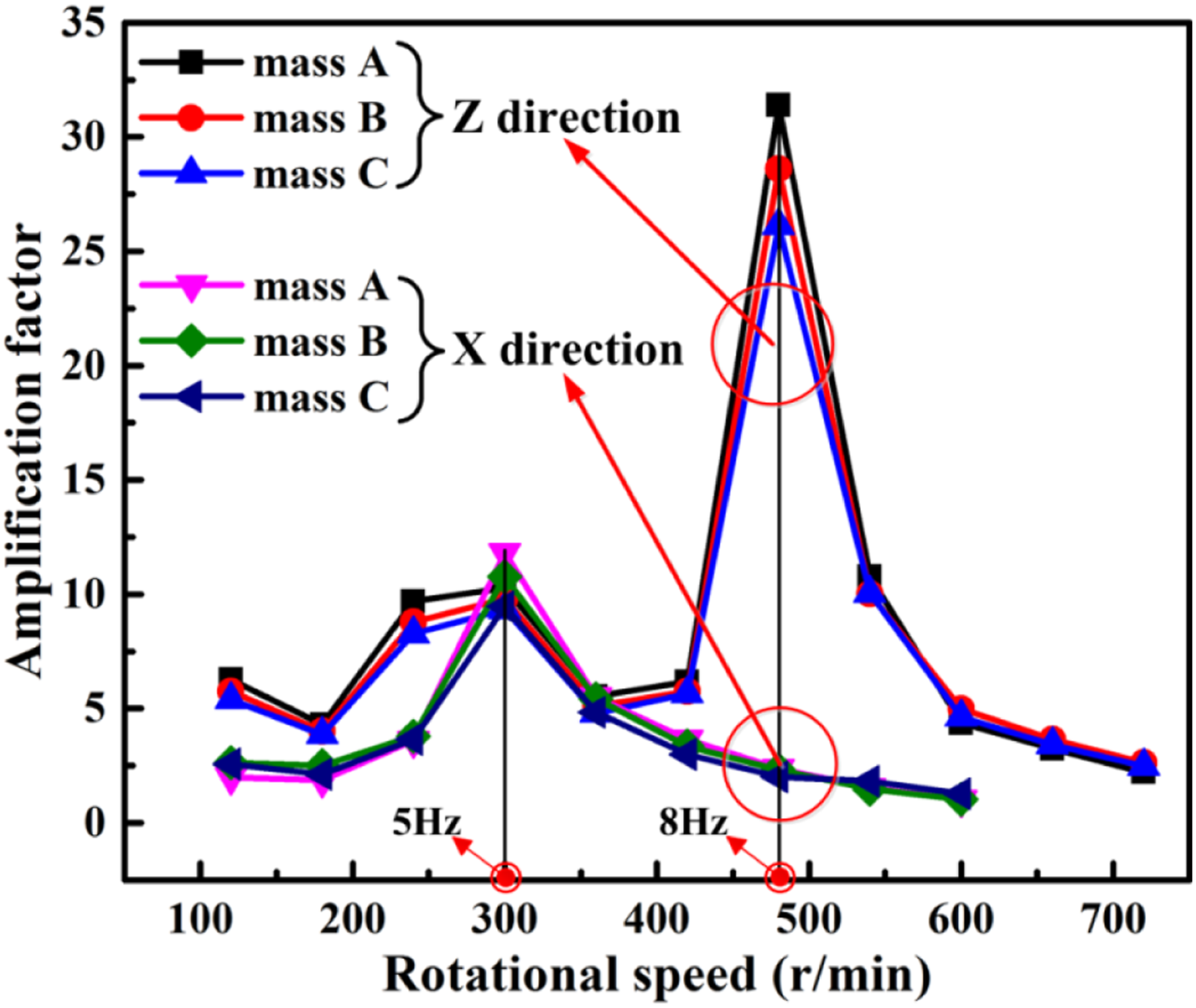
It can be seen from Figure 10 that the variation trend of amplification factors is basically consistent with that of amplitude. The maximum amplification factors in the X direction and Z direction occur at 5 Hz (300 r/min) and 8 Hz (480 r/min), respectively. The amplification factors under different exciting forces are essentially the same both in X and Z directions which follow the law of vibration amplification. 53
Dynamic characteristics comparison among different elastic systems
In order to compare the elastic characteristics of the leaf spring system and disc spring system, the amplitudes and amplification factors of the leaf spring system and disc spring system in X and Z directions are shown in Figure 11. It can be seen from Figure 11 that the amplitude in the Z direction of the leaf spring system is 8.83 mm while that of the disc spring system is 3.3 mm. The amplitude of the leaf spring system is 2.67 times of that of the disc spring system in the Z direction. Similarly, the amplitude in the X direction of the leaf spring system is 3.7 mm while that of the disc spring system is 0.63 mm. The amplitude of the leaf spring system is 5.87 times of that of the disc spring system in the X direction. Furthermore, the amplification factor of the leaf spring system is obviously larger than that of the disc spring system, especially in the X direction. The larger amplitude and amplification factor of the leaf spring system than the disc spring system indicates better dynamic characteristics in the leaf spring system than in the disc spring system. Amplitude and amplification factor of leaf spring system and disc spring system
11
in X and Z directions.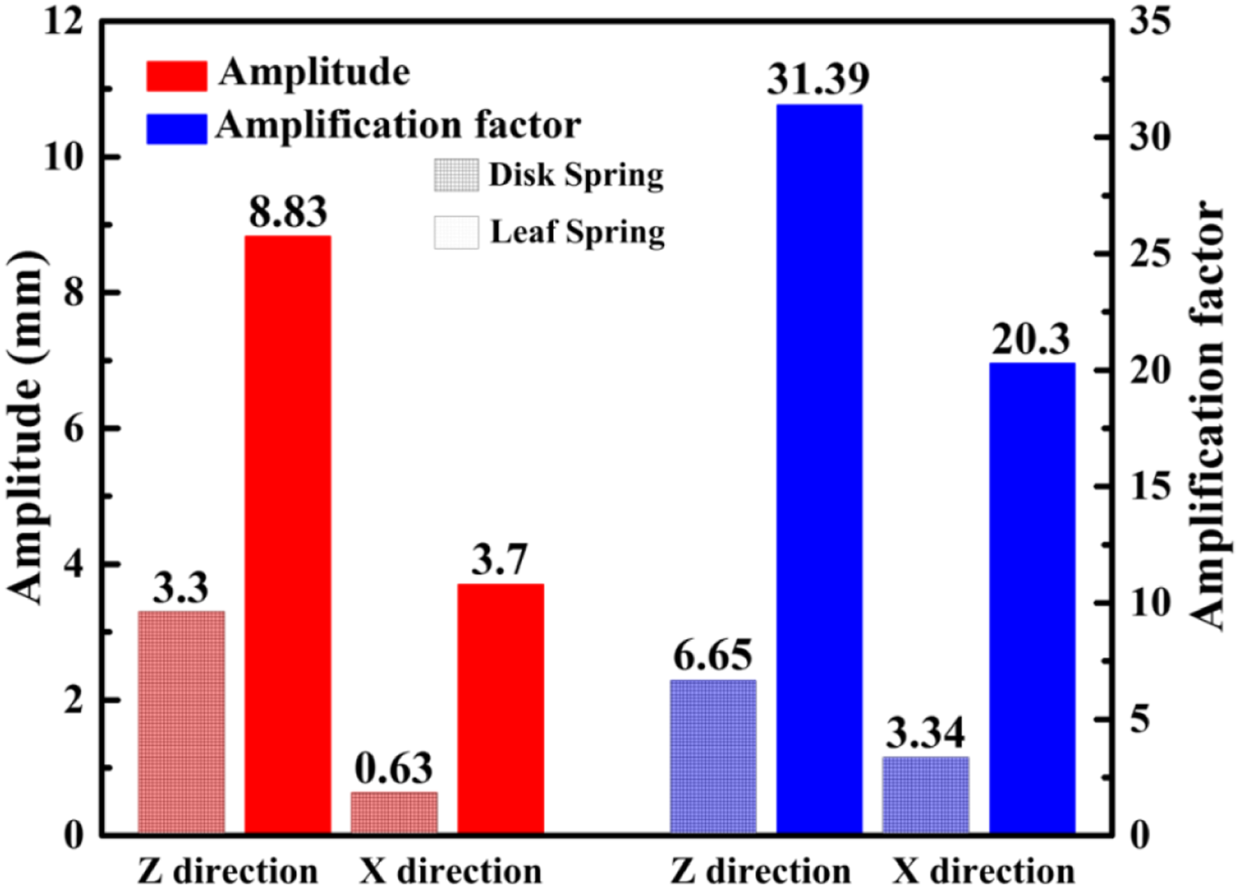
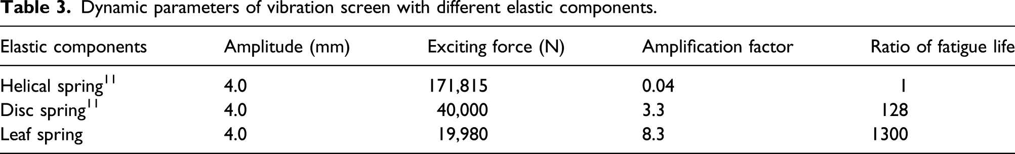
Dynamic parameters of vibration screen with different elastic components.
Conclusion
A new elastic component is designed to reduce the working load, ensure the linearity, and increase the amplitude in the vertical and horizontal directions in vibration screen by studying dynamic characteristics of the leaf spring system. First of all, the modal results show that the leaf spring system vibrates in horizontal and vertical directions in first and second mode shapes, respectively. It is conducive to loosening and moving the particles on the vibration screen. Meanwhile, the stiffness of the leaf spring system in horizontal and vertical directions can be adjusted more easily than the disc spring system, which brings the frequency in horizontal and vertical directions closer. In addition, the results of the amplitude test and analysis show the amplitude and amplification factor of the leaf spring system increases first and then decreases both in horizontal and vertical directions with the increase of rotation speed. The maximum amplitude and amplification factor in the horizontal direction appear at 300 r/min (5 Hz) while those in the vertical direction appear at 480 r/min (8 Hz), which are higher than those in the disc spring system. Moreover, the amplitude of the leaf spring system increases proportionally with the increase of exciting force, indicating the excellent linearity of the leaf spring system with a certain range. Furthermore, the exciting force of the leaf spring system is only 11.6% of that in the traditional helical spring system and around 50% of that in the disc spring system under the same amplitude, which means more energy-saving. Thus, the fatigue life of the key component in the leaf spring system is 1300 times that in the helical spring system and 10 times that in the disc spring system, which indicates the outstanding reliability of the leaf spring system in vibration screen. The above conclusions illustrate the excellent dynamic characteristics in the leaf spring system and provide guidance for vibration screening.
Footnotes
Acknowledgements
The authors are grateful to other participants in the project for their cooperation.
Authors contributions
Jiacheng Zhou designed and conducted the simulation and experiment and wrote the first draft of the article. Hu Chao conducted experimental analyses. Ziqiu Wang and Zhengfa Ren contributed to the systematic review of the literature and data retrieval and extraction. Kuanmin Mao conceived and analyzed the data and drafted the article. Xiaoyu Wang funded this research and provided all the experimental devices.
Declaration of conflicting interests
The author(s) declared no potential conflicts of interest with respect to the research, authorship, and/or publication of this article.
Funding
The author(s) disclosed receipt of the following financial support for the research, authorship, and/or publication of this article: This study was partially supported by the National Natural Science Foundation of China under grant no.U19A2072.
Data availability statement
Some or all data, models, or code that support the findings of this study are available from the corresponding author upon reasonable request.