
Abstract
In the present work, a new dynamical model with a single rigid frame driven by two pairs of vibrators, of which each pair of vibrators is engaged with each other by gear mechanism, is proposed to explore the composite synchronization of the system. The motion differential equations and vibration responses of the system are given first. The theory condition for achieving composite synchronization of the system is obtained, by using the average method to deduce the average torque balance equations of the two pairs of vibrators. According to the Hamilton’s theory, the system stability condition is presented, and it is mainly determined by the structural parameters of the system. The synchronous stable regions and stability ability versus the key parameters of the system are qualitatively discussed in numeric, and further quantitatively verified by simulations. It is shown that, in engineering, the reasonable working points of the system, should be selected in the region where the stable phase difference of the two pairs of vibrators is stabilized in the vicinity of zero. Only in this way, can the exciting forces of the two pairs of vibrators be positively superposed, and the linear motion of the system in the vertical direction be realized.
Introduction
There are many vibration problems in engineering and technology fields, and they are mainly referred to vibration suppression, vibration control, and vibration utilization. For the first two aspects, which are related to the vibration isolations; while for the third aspect, one of the most important representatives is the synchronization of vibrators (generally unbalanced rotors driven by motors), based on which many new vibrating machines are invented, designed, and manufactured, and more and more researchers are inspired to study it.
In connection with the synchronization of vibrators, we should date back to the findings by Blekhman,1–3 who gave the theoretical investigation of synchronization of two identical vibrators firstly by using Poincare small parameter method, followed by which he developed this method to be so-called the method of direct motion separation and led to the registrations of many patents. Inoue et al.
4
gave the synchronization of a mechanical system with multiple cycles by using the perturbation method, including the synchronization problem with two (or three) times frequency. Considering the effects of damping of the system, Wen et al.5,6 not only developed the synchronization theory of vibrators and studied the synchronization with n (n
The great engineering applicable prospects of synchronization theory have attracted more and more scholars and engineers to pay their attentions to investigate it. Such as Balthazar et al.7,8 discussed the synchronization problem of two or four non-ideal sources on a flexible portal frame structure by using a numerical method, of which a particular phenomenon called as Sommerfeld effect was revealed. Fang and Hou 9 studied the synchronization characteristics of the rotor-pendulum system and also revealed the synchronous behavior of the system which is determined by the geometry parameters. 10 The synchronization of the two vibrators with a common rotational axis in a far-resonant vibrating system is presented by Chen et al., 11 where the stability of the system for different key parameters is discussed in detail. Zhang et al. 12 studied the synchronization problem of a far-resonant vibrating system with three rollers driven by two vibrators considering the dry friction effect as well as the stability of a vibrating system driven by two vibrators with Sommerfeld effect. 13 Kong et al. 14 revealed the phase and speed synchronization control of four eccentric rotors driven by induction motors in a linear vibratory feeder using the adaptive sliding mode control algorithm, and also studied the composite synchronization (including vibration synchronization and control synchronization) of three eccentric rotors 15 as well as the composite synchronization of a vibrating system with a mass-spring rigid base driven by four vibrators. 16 For the synchronization problem of vibrators, one of the difficulties lies in the mathematical modeling and the corresponding solutions. For the mathematical modeling, Lagrange’s equation method is commonly used, and some new variational principles and the semi-inverse method can also easily overcome the Lagrange crisis. 17 In light of solving the motion differential equations of the system, there are generally transfer function method and amplitude-frequency response method for linear systems and solving the nonlinear differential equations by the variational iteration method. 18
Generally speaking, the synchronization problem combining with more than one type of synchronization manner, is called as the composite synchronization of vibrators. In the above literatures, most researches are focused on vibratory synchronization or composite synchronization consisting of controlled synchronization and vibratory synchronization. However, there is an another synchronization manner, i.e., the composite synchronization combining forced synchronization with vibratory synchronization is less considered, and this is just the aim of the present work.
In this paper, we restrict our attentions to a far super-resonant vibrating system (i.e., the operating frequency of the system is about 2–10 times of its natural frequency), and a new dynamical model characterized by combining forced synchronization with vibratory synchronization is proposed to study the composite synchronization of the system in detail.
The organization of this paper is as follows. The dynamic model of the system and the motion differential equations are given first, which are followed by giving the theory conditions on composite synchronization and stability. Some numerical qualitative analyses are provided in “Numerical qualitative analyses based on the above theoretical results” section. Next, simulations are carried out to further quantitatively examine the validity of the theoretical and numerical qualitative results. Finally, the conclusions are stressed.
Dynamical model and motion differential equations of the system
As shown in Figure 1, a new dynamical model consists of a rigid frame (RF) (mass m) and two pairs of vibrators; the latter is symmetrically distributed on the left and right sides of the RF. Each pair of vibrators is engaged with each other by the gear mechanisms (reference radius is denoted by D) and driven by one induction motor; in this case, their forced synchronization is implemented; while the two pairs of vibrators can implement vibratory synchronization. The total system is driven by two induction motors and embodies a composite synchronization manner consisting of forced synchronization and vibratory synchronization.
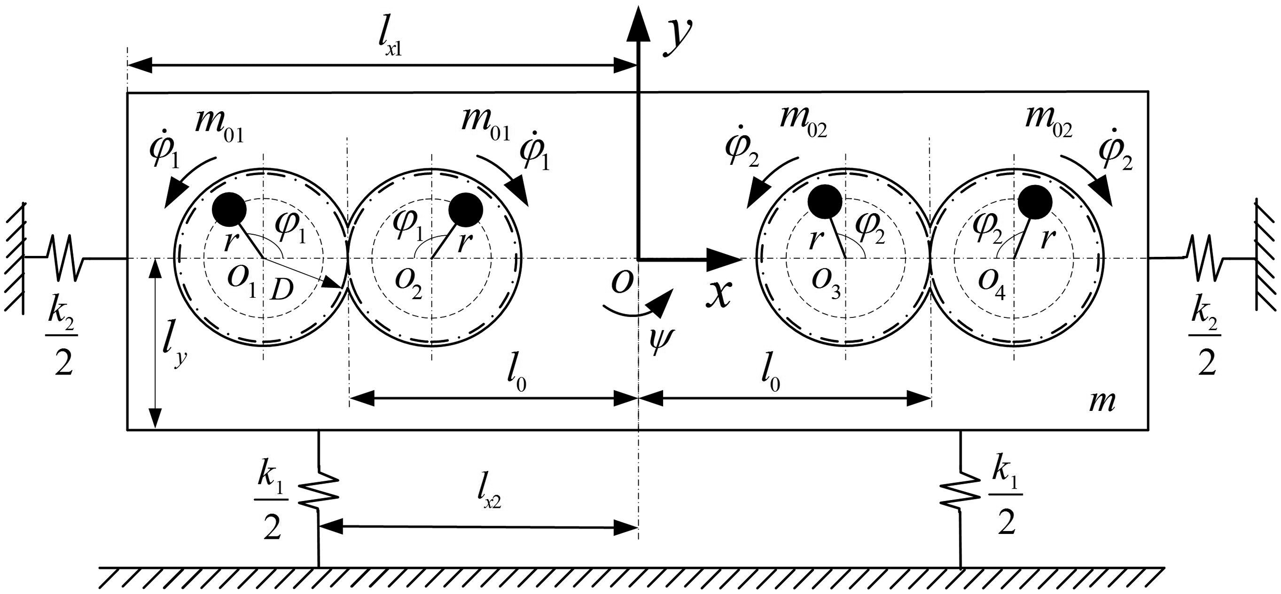
Dynamical model of a considered vibrating system with two pairs of vibrators driven by two motors.
The RF is connected with the foundation by springs with stiffness (see k1 and k2), each vibrator rotates around its own axis Oi (i = 1, 2, 3, 4), their rotating phases are denoted by φ1 and φ2, and the other parameters can be seen in Figure 1. The total system exhibits three degrees of freedom: displacements in x-and y-directions and swing angle about its centroid O, denoted by x, y, and
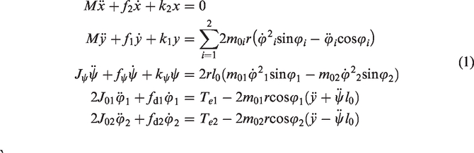
Substituting the kinetic energy, the potential energy, and the energy dissipation functions of the system into Lagrange’s equations, the motion differential equations of the system are presented directly as
Theory conditions on composite synchronization and stability of the system
Since the two unbalanced rotors of each pair of vibrators connected with each other by the gear mechanism are identical, we can set as
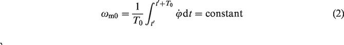
Because the vibration excited by the two pairs of vibrators is periodic, which results in the periodic change of the average angular velocity
It is assumed that the average phase of the two pairs of vibrators is

From equation (3), we have

If the two pairs of vibrators can implement synchronous operation in the steady state, we set as


For equations (5) and (6), using the Transfer Function method,
19
the responses of equations (5) and (6) are presented in form


Theoretical condition of implementing composite synchronization of the system
Differentiating equations (7) and (8) and inserting the results into the last two formulae of equation (1), then integrating them over
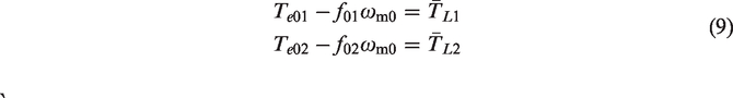


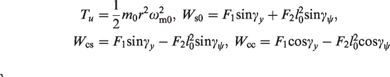
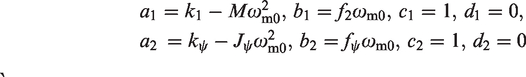
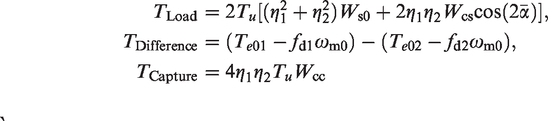
In equations (9) to (11),
The sum and subtraction of the two formulae in equation (9), and after the rearrangement, yields to

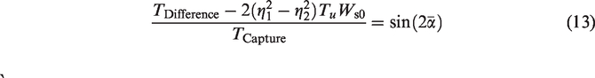
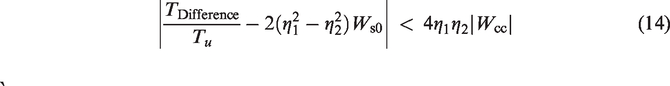
From equation (13) and due to the fact of
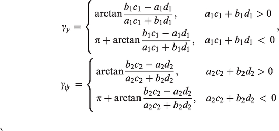
Besides, from equation (13), one can know that, under the precondition of satisfying the composite synchronization, the expression of the phase difference between the two pairs of vibrators,
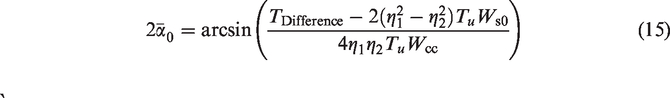
In equation (15), generally speaking,
The ratio between the frequency capture torque and the total load torque of the system is here defined as the composite synchronization ability coefficient of the two pairs of vibrators, denoted by
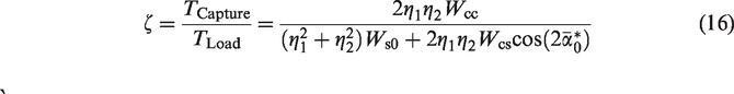
The greater the value of
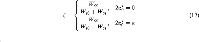
When the two pairs of vibrators are identical, i.e.
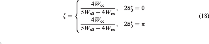
Under the condition that the two pairs of vibrators are not identical, for example, when
Theoretical condition on stability of the composite synchronous states
Since not all the synchronous solutions in equation (15) are stable, so it is very necessary to further investigate the stability of solutions of the system. According to Blekhman et al.,1,5 the stable solutions of the phase difference for the composite synchronous states should correspond to the minimum point of Hamilton’s average action amplitude.
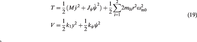
The kinetic energy (T) and the potential energy (V) of the system are obtained by
Thus, the average kinetic energy (
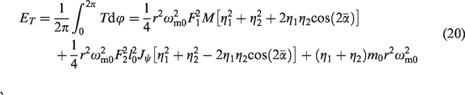
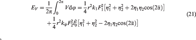
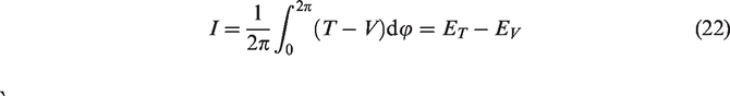
Based on equations (19) to (21), the Hamilton’s average action amplitude of the system over one period, denoted by I, is deduced by
From Blekhman et al.,1,5 we know that the stable phase difference (SPD) between two pairs of vibrators should satisfy the Hamilton’s theory condition of stability of the system. In other words, the second-order derivative of I with respect to
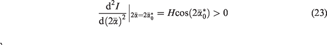
Hence, equation (23) is the stability condition of the composite synchronous states of the system. The SPD
For equation (23), the greater the absolute value of H, the stronger stability of the composite synchronization states of the system, i.e., the stronger the anti-interference capability of the composite synchronization system.
In the next sections, we will additionally present some numerical qualitative analyses and simulations to support the above theoretical results. It should be pointed out that the theoretical results in “Theory conditions on composite synchronization and stability of the system” section are deduced by using the average method, and the numerical qualitative analyses in “Numerical qualitative analyses based on the above theoretical results” section are given by the theoretical results of “Theory conditions on composite synchronization and stability of the system” section, which aims at further qualitatively reveal stability characteristics of the system; while simulations in “Simulations” section are carried out to quantitatively verify the feasibility of the previous theoretical and numerical qualitative results, by an another numerical method called the Runge–Kutta method which is directly applied to motion differential equation of the system (i.e., equation (1)).
Numerical qualitative analyses based on the above theoretical results
According to the above theory results, in this section, some numerical qualitative discussions are given to further reveal the stability characteristics of the system. The two driving induction motors are selected to be the same: model is three-phase squirrel-cage (50 Hz, 380 V, 6-pole, 0.75 kW, rated speed 980 r/min); the rotor resistance
It should be noted that the natural frequency of the system in x-direction does not need to be considered due to that the exciting forces of the two pairs of vibrators in x-direction are counteracted with each other. So, based on the above given values of parameters, the main natural frequencies of the system are calculated as
Stable regions of the system
Based on the stability criterion in equation (22) and considering the parameters of the system, the synchronous and stable regions of the system are shown in
Synchronous and stable regions of the system for
From Figure 2(a), one can obviously see that, under the precondition of the two pairs of identical vibrators (i.e.,
According to the above discussions, in engineering, the ideal working point of vibrating machines should be selected in the gray area (I) of Figure 2(b), which can be satisfied by adjusting the values of
Stability ability of the system
The given parameters of the system are inserted into equation (23), we can plot the stability ability coefficient of the system, see Figure 3, in which the greater the absolute value of the stability ability coefficient, the stronger the stability of the system.
Coefficient of stability ability of the system for
Figure 3 is the contour map of the stability ability, which is divided into five regions according to the value of coefficient of stability ability: regions I, II, III, IV, and V. These areas are distinguished by different colors, and each of them shows different ranges of values of the coefficient of stability ability in Figure 3. For example, the area with royal blue in region V indicates that the stability ability coefficient is in the range of 687.5–1522. Compared with Figure 2(b), in Figure 3, the regions I and II correspond to the fact of
In a word, by the overall comparisons of the synchronous and stable regions, and the stability ability of the system, see Figures 2 and 3, in engineering, we should select the greater value of
Simulations
In order to further verify the feasibility of results of the previous theory and numerical qualitative analyses, another numerical method called the fourth-order Runge–Kutta routine is directly applied to equation (1). Here, taking
In this section, the total operational process of the system can be divided into four stages: (i) the first stage is the starting stage of the transient process of the system; (ii) the second stage is the synchronous and stable operational stage of the vibrators (i.e., convergence state of the system); (iii) the third stage is the transient stage of the system when adding a disturbance to the motor 2 at 40 s; (iv) the fourth stage is the synchronous and stable operational stage of after adding a disturbance (i.e., convergence state of the system). The above four stages are described in detail as follows.
Simulation results in Region (I) of Figure 2
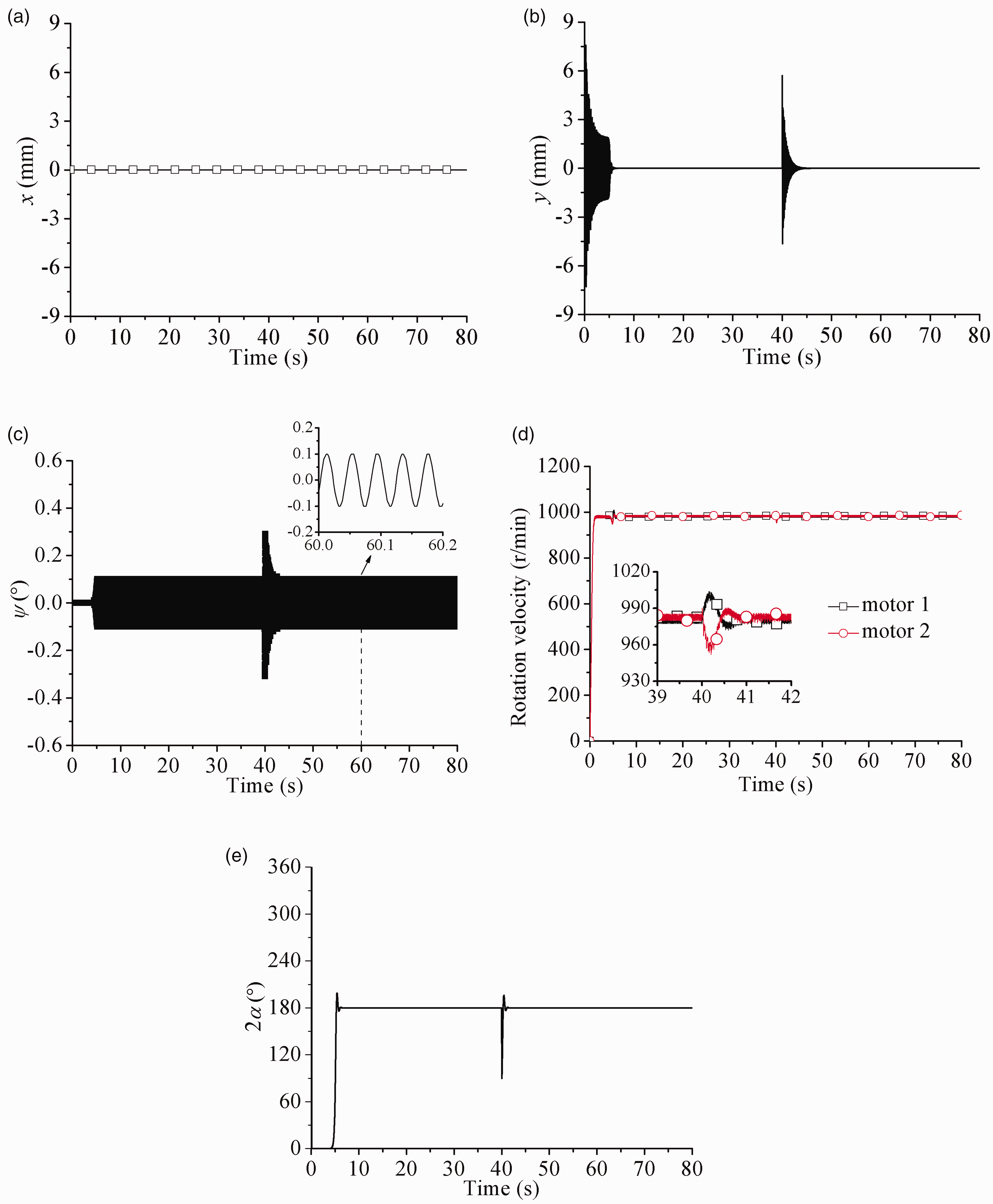
We set as
Simulation results in region (I) for
From Figure 4(d), one can see that the synchronous rotational velocity of the system is 980 r/min (i.e.,
In the first stage of Figure 4, the two motors begin to operate at the same time when supplied with power, during this transient process, the operating frequencies of the two pairs of vibrators pass through the resonant region of the system and excite the corresponding resonant responses in y-direction, see Figure 4(b). With the continuously increasing rotational velocities of the two motors, as shown in Figure 4(d), they reach their rated values, and with the help of the coupling torques, the system is stabilized rapidly, i.e., the system enters the second stage. In other words, after the starting transitional period about 4 s, the system begins to be in the convergence state; in this case, the system reaches composite synchronization and ensures a stable operation state and the corresponding synchronous and stable state: the synchronous and stable rotational velocity is 980 r/min, the SPD
Besides, the motion types, phase relationships, and displacements of the system in the steady state are as follows: In x-direction: the response is zero, see Figure 4(a). For y-direction, since In the starting process, the resonant response with respect to
The above facts on synchronous and stable states and displacements of the system are all well coincidence with what are illustrated in Region (I) of Figure 2(a) and (b).
Simulation results in Region (II) of Figure 2
Here, the spring stiffness:
Simulation results in Region II for
Since the two pairs of vibrators are identical, as well as the two driving motors, they reach their rated speed at the same time during the starting process, and the system implements composite synchronization and ensures a certain stable operating state in the steady state. At the first stage of the system, with the increasing rotational velocities of the two motors, as shown in Figures 5(d) and (e), the phase difference between the two motors changes from 0° to 180° and their rotational velocities reach the rated values. In the second stage, the coupling torques among the two pairs of vibrators increases, which make the system quickly reach a stable state (i.e., convergence state), at this time, the stable state of the system: the synchronous rotational velocity is 980 r/min, the SPD of the two motors
In engineering, the working point of the system should be selected in Region (I) of Figure 2(b); in this case, the greater vibration amplitude in the vertical direction can be realized, while the vibrations in x-direction are exactly compensated with each other. Utilizing the characteristics in Region (I) of Figure 2(b), a new type of vibrating machines with high vibration strength can be designed.
Conclusions
The following conclusions are stressed: The theoretical condition of implementing composite synchronization of the two pairs of vibrators is obtained as well as the stability condition of the composite synchronous states. The former is mainly determined by the characteristics of the driving motors, while the latter is dependent on the structural parameters of the system. The composite synchronization ability The stable regions of the system are divided into two main areas by the key structural parameter In engineering, the value of Based on the present work, a new type of vibrating machines with high power, such as vibrating compactors, and vibrating screens, can be designed. In engineering, the ideal working point of composite synchronous vibrating machines is often considered to be in a far super-resonant state due to the fact of its strong stability, just like the model discussed in present work. In the future researches, the synchronization and stability characteristics in the near-resonant state should be further analyzed.
Footnotes
Declaration of conflicting interests
The author(s) declared no potential conflicts of interest with respect to the research, authorship, and/or publication of this article.
Funding
The author(s) disclosed receipt of the following financial support for the research, authorship, and/or publication of this article: This work was supported in part by the National Natural Science Foundations of China [52075085] and the Fundamental Research Funds for the Central Universities [N2103019].