
Abstract
In this paper, a synchronous vibration control method was proposed to avoid the high-cycle fatigue fracture of aeroengine rotor blade. Firstly. The harmonic force, causing synchronous vibration, was derived by Fourier series expansion by the mean of simplifying the aerodynamic exciting forces into the periodic rectangular pulse wave forces. It was found that the synchronous vibration can be controlled by adjusting the primary excitation forces parameters. Based on this, the additional secondary excitation forces were introduced to control the synchronous vibration caused by primary excitation forces. Secondly, the influences of the number, position, direction, duration of additional secondary excitation forces and the phase difference between additional secondary excitation forces and primary excitation forces on the synchronous vibration control were obtained through theoretical analysis, which was simulated and verified by a single-degree-of-freedom model. Thirdly, a high-speed straight blade test bench was established, and the feasibility of the method in controlling synchronous vibration of rotor blade was proved by adding additional magnet excitation forces on the basis of fixed magnet excitation forces. Finally, the suppression strategy of synchronous vibration of rotor blade by introducing additional secondary excitation forces was given. It can provide theoretical and technical support for effectively controlling the synchronous vibration amplitude and avoiding the high-cycle fatigue fracture of rotor blade in engineering practice.
Introduction
According to literature statistics on rotor blade failures, high-cycle fatigue (HCF) is a common failure mode of rotor blade in aero-engines. The reason of HCF is that the frequency or harmonic frequency of excitation forces is consistent with the vibration frequency of blade, and synchronous vibration of rotor blade occurs. As the speed of modern aero-engine is faster and faster, the centrifugal load and aerodynamic load in the working condition is also increasing. When the rotor blade resonates, the rotor blade will endure relatively large alternating load on the basis of the above two kinds of loads. The vibration frequency of the resonant blade is very large, which is from hundreds of Hertz to thousands of Hertz. The number of alternating vibrations of rotor blade will be more than 106 in an hour. This resonance is very harmful to the blade, which often leads to cracks or even fracture of the blade.
The damage of synchronous vibration can be avoided by modifying blade shape in the design phase, but this method is difficult to avoid all synchronous vibration points. So some available methods are needed to suppress the synchronous vibration when the synchronous vibration that occurs is harmful to the blade.
For example, the blade vibration suppression method based on piezoelectric shunt damping technology was study.1,2 The piezoelectric material is attached to the vibrating structure to convert the mechanical energy of the vibration into electrical energy, which is consumed by the dissipation circuit to suppress structural vibration. It can be known that piezoelectric shunt damping technology is a passive vibration suppression technology. In the application of aero-engine rotor blade vibration suppression, it can be divided into two types according to the different sticking position: the blade surface and the blade disk.
The piezoelectric shunt damping technology distributed on the rotor blade is an intrusion method, which will inevitably affect the flow field, affects the aerodynamic performance.3,4 The mounting position of the piezoelectric material also has a greater influence on the vibration suppression effect. When the mounting position is in a small stress area, the vibration suppression effect will be reduced. In order to avoid the influence on the aerodynamic performance, the piezoelectric plates are mounting on the blisk, and the vibration suppression is realized by the coupled vibration of the blade and the blisk.5,6 As stated in the paper, 7 the distribution of the piezoelectric materials on the blisk can only bring greater damping to the dominant mode of the blisk and the coupled vibration mode of the blisk and blade, while the damping of the dominant mode of the blade is smaller. The introduction of piezoelectric materials will inevitably lead to an increase in the total mass of the wheel, and will be restricted in the high-speed and high-performance engine rotor blade. Recently, piezoelectric damping technology has mainly focused on how to optimize layout schemes and improve circuit technology in order to increase the efficiency of vibration suppression.8,9
The resonance of rotor blade is caused by the instability of air flow, so how to reduce the unevenness of the air flow caused by the front stage stator is the key to reducing the blade synchronous vibration. Rao et al. 10 proposed to open blow holes on the trialing edge of the four stators to reduce the unevenness of the air flow, and control the air flow velocity of each blow hole through independent micro-electro-mechanical system, so as to achieve noise reduction and vibration suppression. Flotow et al. 11 proposed to insert flow obstructions and/or gas injections upstream of vibrating blades, and the power flow into blades is reduced by means of cancellation within a modal power integral. Both of the above methods have adverse effects on aerodynamic performance. Maldonado et al. 12 used synthetic jet to control the vibration of wind turbine blade. These methods are similar.
There are also some active control methods for blade vibration by placing electromagnetic excitation on the casing, but only in the structure and strategy are described, and the specific vibration control method is not mentioned.13–15 In addition to the above control methods, there are also dry friction damping to achieve blade vibration suppression.16–18 But the rotor blade design with a friction damper is an engineering challenge. 19
In this paper, starting from the adjustment of the parameters of the aerodynamic excitation forces that induces the synchronous vibration of rotor blade, a method of introducing additional secondary excitation forces (ASEF) to achieve the synchronous vibration control is proposed.
Firstly, the harmonic force amplitude formula of the synchronous vibration of rotor blade is derived by Fourier series expansion (FSE) with simplifying the aerodynamic excitation forces into the form of periodic rectangular pulse wave forces (PRPWF). The definition of ASEF is given, and the harmonic amplitude of synchronous vibration of rotor blade after introducing ASEF is derived. Three control laws are summarized to control the harmonic force amplitude of blade synchronous vibration by introducing ASEF, and the simulation results are verified. Combined with the instability of the force amplitude and the position angle error of the excitation force in the engineering practice, the feasibility and reliability of synchronous vibration control of rotor blade with ASEF are verified by simulation. The experiment of introducing six ASEF on the basis of six uniformly distributed magnet excitation forces verifies the feasibility of the blade synchronous vibration control method proposed in this paper. Finally, the synchronous vibration suppression strategy based on the introduction of ASEF is given.
The relationship between excitation forces and synchronous vibration of rotor blade
When the frequency or harmonic frequency of excitation forces is the same as a certain order vibration frequency of rotor blade, the rotor blade will vibrate synchronously. The excitation forces on rotor blade mainly come from the airflow disturbance caused by the upstream support plates, stator blades, and nozzles. The change of flow velocity and static pressure of the airflow after passing through the stator blades is as shown in Figure 1. The exciting forces caused by the airflow velocity change can be approximately rectangular pulse wave forces. And the static pressure change is smaller than change of the airflow velocity, so the disturbance force on the rotor blade can be simplified as a PRPWF.20 In fields of other rotating machinery, flow and pressure instability caused by blade rotation are also very common.21,22
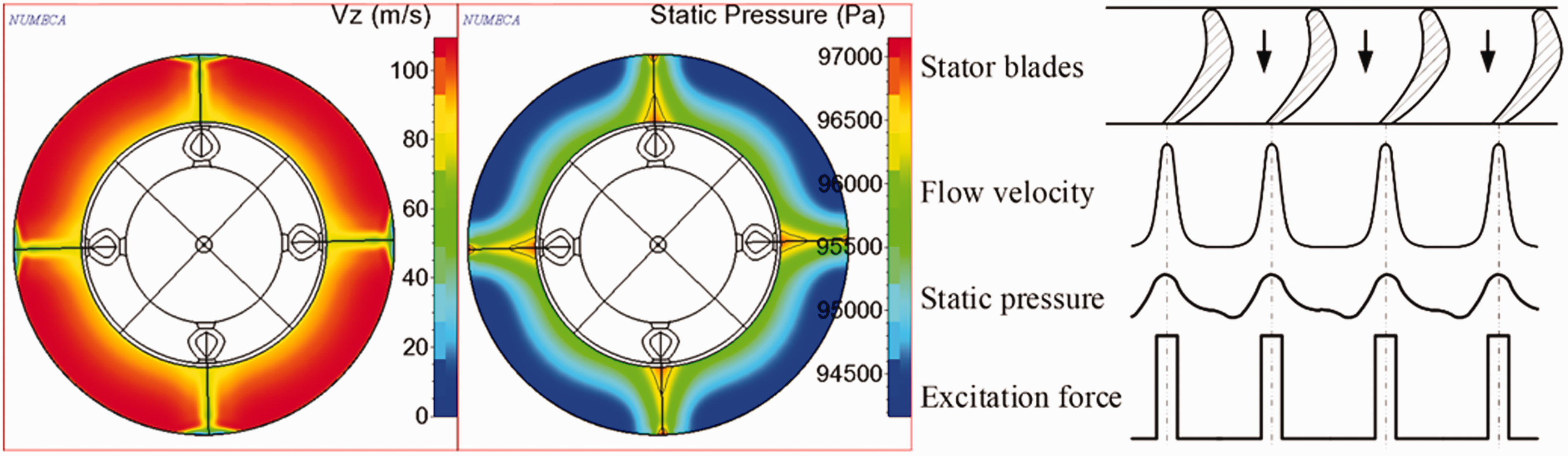
Velocity and pressure distribution behind stator blades and simplified excitation force.
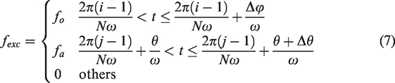
The PRPWF can be expressed as
From the knowledge of vibration mechanics,
23
the forced vibration equation of a SDOF rotor blade can be simplified as

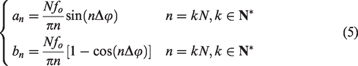
For synchronous vibration of rotor blade, equation (2) can be written as follows
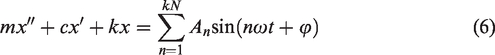

It is clear that there is no direct relationship between the harmonic force amplitude An of PRPWF and the rotation angular frequency. However, it is related to the number of excitation forces N, the force amplitude fo of PRPWF, the EO n, and the duration of excitation forces Δφ. When the parameters of excitation forces generated by the incoming flow disturbance are fixed, the harmonic amplitude of excitation forces is only determined by the EO of synchronous vibration of rotor blade. Nfo determines the magnitude of harmonic force amplitude, Δφ affects the zero-crossing point of harmonic force amplitude, and the overall trend of the harmonic force amplitude decreases with the increase of the EO n. Figure 2 shows the variation trend of harmonic force amplitude obtained by equation (2) with excitation forces duration (indicated by the duty cycle in the figure) and EO. In order to eliminate the influence of Nfo, normalization amplitude is adopted.
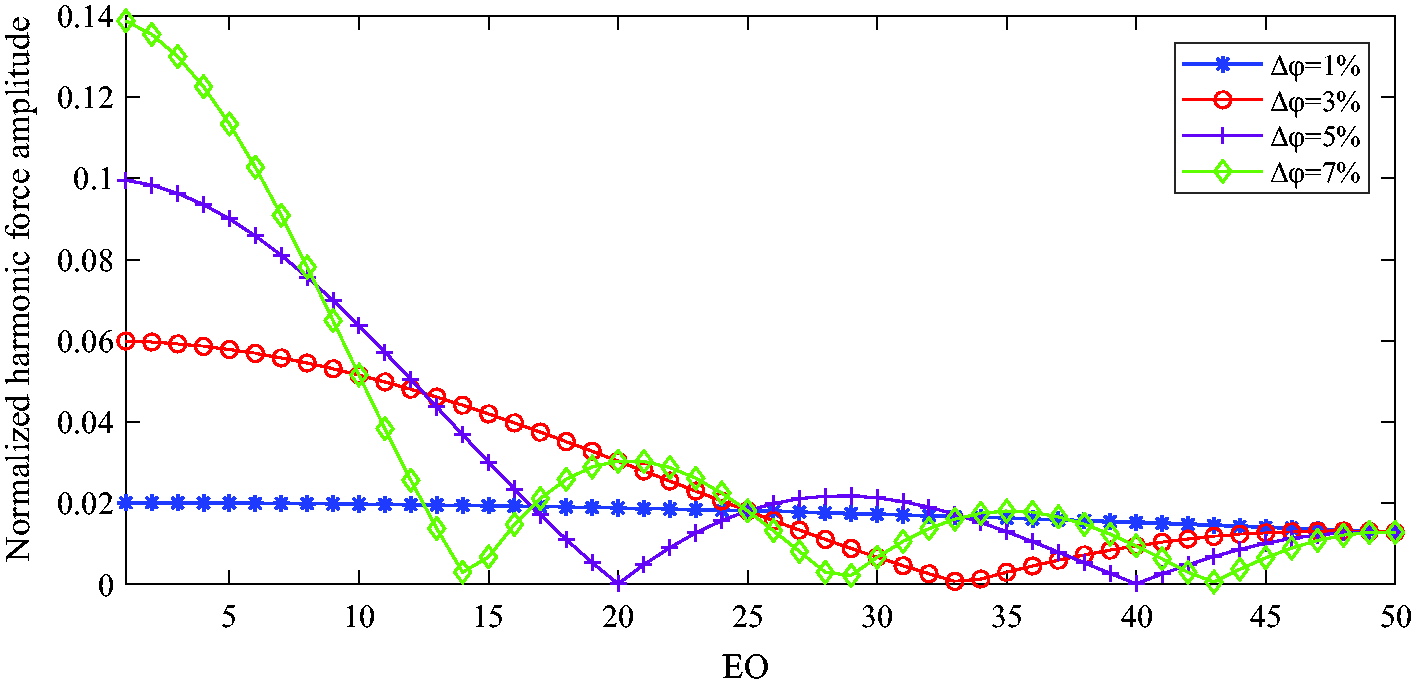
The trend of harmonic force amplitude with EO and excitation force duration under PRPWF.
It can be seen from Figure 2 that when the duration of excitation forces is fixed, the component of harmonic force amplitude of excitation forces under certain EO will be very small, and the synchronous vibration of rotor blade at this EO will not be obvious or even not occur. Due to the EO of synchronous vibration is also related to the number of excitation forces, the synchronous vibration points shown in the figure do not necessarily occur for all the EO.
From the above analysis, it can be known that the harmonic component of excitation forces affects the occurrence of synchronous vibration of rotor blade. When the PEF cannot be changed, it can be considered to change the harmonic component of the excitation forces by introducing a suitable ASEF at specific EO. If the ASEF are also periodic, the harmonic component of ASEF at a specific EO can be obtained by FSE and can be controlled by changing the parameters of ASEF so as to control the synchronous vibration of rotor blade.
The effect of introducing ASEF on the occurrence of synchronous vibration of rotor blade
Derivation of synchronous vibration harmonic force amplitude when ASEF are introduced
This paper proposes a method of introducing ASEF to control the synchronous vibration of rotor blade by changing the force amplitude of specific order harmonic component. The ASEF introduced are regulated as follows: The number of ASEF introduced cannot be more than the number of PEF; All ASEF parameters introduced are the same, including force amplitude, duty cycle, direction of ASEF; The position of the introduced ASEF is arranged after different PEF circumferential positions, and the phase difference between ASEF and corresponding PEF is the same.
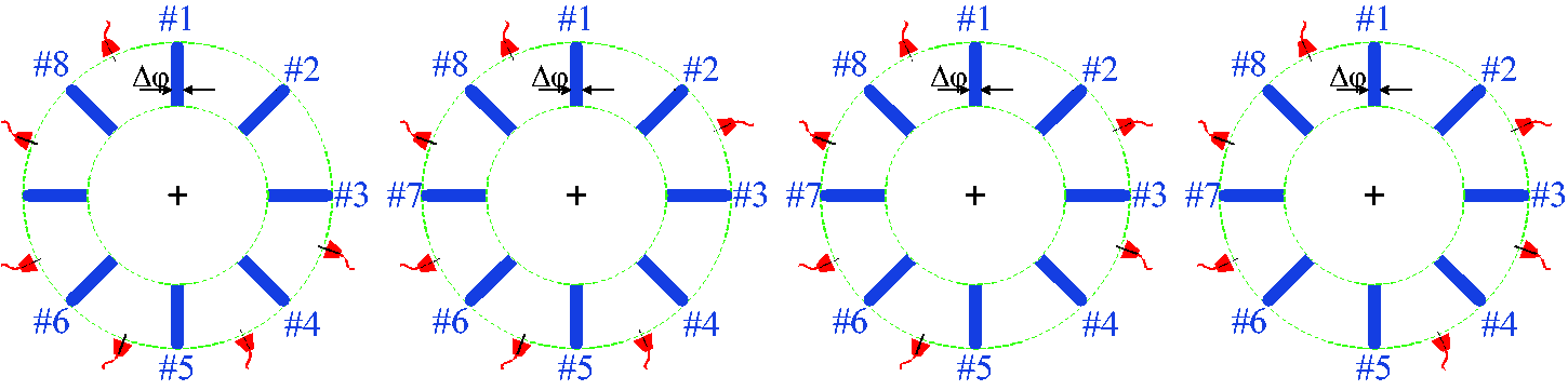
The schematic distribution of PEF and the arrangement of ASEF are as shown in Figure 3. The number of PEF distributed is eight in the figure, and the number of ASEF is four. Meanwhile, the position θ and duration Δθ (in radians) of ASEF are expressed.
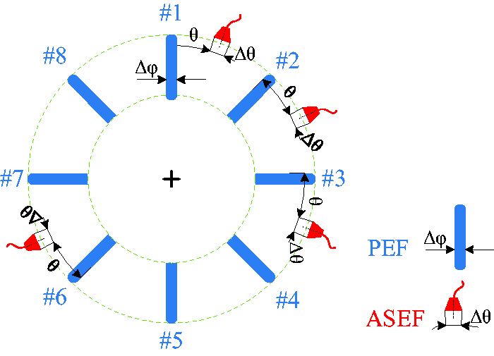
Schematic diagram of uniform distribution of PEF and introduction of ASEF.
Note that the ASEF are also PRPWF, its amplitude is fa, and the mounting position θ represents the phase difference with the corresponding PEF. In the same way, the harmonic component after the introduction of ASEF can be calculated according to FSE. The equation of excitation forces can be expressed as
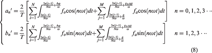
Introducing Mfa=λNfo, the harmonic component of the original synchronous vibration point (n/N∈
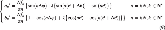
Noting:
Calculate the partial derivative of

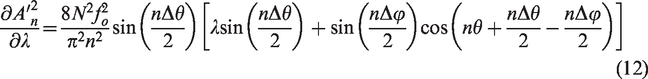
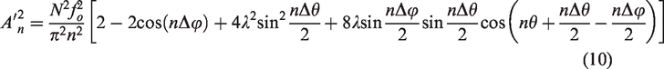
Comparing the harmonic force amplitude An in equation (6) with the harmonic force amplitude
The following introduces some effects of synchronous vibration control by introducing ASEF, including the influence of mounting position, number, and application direction of ASEF.
The effects of the parameters of ASEF on synchronous vibration control
The influence of different distribution position on the control effect when the number of ASEF is fixed
When the number of ASEF is not equal to the number of PEF, there will be a variety of distribution positions of ASEF. For example, when the number of PEF and the number of ASEF are both eight, each ASEF corresponds to the relative position of PEF one by one. When the number of ASEF is six, there are four distribution modes of ASEF, as shown in Figure 4.
Uncertainty of mounting position of ASEF.
According to equations (8) and (9), when the relative position between the ASEF and the PEF, and the parameters of ASEF are the same, the harmonic amplitude of synchronous vibration of rotor blade is shown in equation (10). That is, when the number of ASEF is determined, the distribution position of ASEF can be arbitrary, but the relative position with the PEF is required to be determined.
From this conclusion, if the phase difference between the ASEF and the corresponding PEF exceeds the uniformly distributed interval phase of PEF, it can be regarded as the phase difference between the ASEF and the next PEF. In other words, the valid distribution position of ASEF is the uniformly distributed interval phase of PEF, which is periodic. 2. Periodicity of the installation position of ASEF
As shown in Figure 5, when the ASEF exceeds the interval phase of PEF, the ASEF can be regarded as in the next interval phase. Combined with the conclusion given in the previous summary that the distribution position of ASEF is independent of PEF, it can be seen that the effect of ASEF in the interval phase is the same as that in the original interval phase.
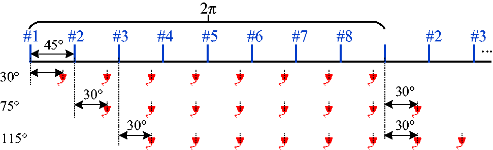
Periodic relationship between ASEF and PEF.
From the derivation equation (10) of harmonic force amplitude to the mounting position θ of ASEF, it can be known that when the value range of θ is (0, 2π), the value of nθ is (0, 2πn). And the number of cycles that θ affects harmonic force amplitude is n, which is consistent with the EO of synchronous vibration of rotor blade. According to the validity of the mounting position, the availability range of θ is (0, 2π/N), then the value of nθ is (0, 2πn/N), and n/N∈ 3. The influence of the direction of ASEF on synchronous vibration control
Taking a cantilever beam as an example, when the original load is fixed, the ASEF can be applied in two directions relative to the original load, in the same direction and in the opposite direction with the original load, as shown in Figure 6.
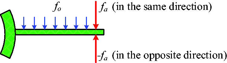
Schematic diagram of introducing ASEF in the same direction or the opposite direction.
Only the loading direction of ASEF changes. According to equation (10), it can be known that when the mounting position of fa moves half a period π/n, its application effect is consistent with −fa. This also means that the ASEF introduced in the same direction and in the opposite direction can achieve the same control effect of the harmonic amplitude of synchronous vibration. 4. The influence of position and magnitude of ASEF on synchronous vibration control
It can be seen from equation (11) that when
And the value of the mounting position θ of ASEF is
The maximum and minimum values of
According to Mfa=λNfo defined above, and λ is defined as the total force coefficient of excitation forces, which is determined by the number and amplitude of ASEF. The extreme value of the total force coefficient to synchronous vibration amplitude is analyzed as follows:
When the other parameters are fixed and λ takes the value in equation (15), 5. The influence of the number of ASEF on other synchronous vibration points
According to the definition of ASEF, the number of ASEF should not be more than the number of PEF. Therefore, there are two cases: (1) the number of ASEF is equal to the number of PEF; (2) the number of ASEF is less than the number of PEF. The following discusses the influence of different number of ASEF on the original synchronous vibration points and other synchronous vibration points: The number of ASEF is equal to the number of PEF
The number of ASEF is equal to the number of PEF, that is, N = M. For n/N∉
Combining with the previous derivation, it can be known that the force amplitude of each ASEF can be reduced when the maximum number of ASEF is applied. Therefore, the number of ASEF which are consistent with the number of PEF can be optimized. 2. The number of ASEF is less than the number of PEF
In this case, M < N, for n/N∉
Summary of synchronous vibration control laws by introducing ASEF
The method is proposed to achieve synchronous vibration control of rotor blade by introducing ASEF. The harmonic force amplitude at the synchronous vibration point after mounting ASEF is deduced by FSE, which proves the feasibility of the method. Three control laws for introducing ASEF method are obtained: When the number of ASEF is fixed, and the phase difference with PEF remains unchanged, the different distribution positions of ASEF do not affect the control effect. On the contrary, when the number of ASEF is determined, the distribution position can be arbitrary. The phase difference between the ASEF and the PEF has a periodic relationship with the vibration control effect, and the number of the cycles is the value of EO of the synchronous vibration. Furthermore, the number of control cycles between the PEF is the ratio of the value of EO to the number of PEF. The same control effect can be achieved by applying in the same direction and in the opposite direction, but there is a half cycle difference between them.
Simulation to verify the control effects with the ASEF
Introduction of simulation model
In order to simplify the analysis, the simulation model adopts a SDOF vibration model. And the vibration equation has been given in equation (2). The excitation forces are represented by PRPWF. The duration of the excitation forces of rotor blade is expressed by the duty cycle of PRPWF. In order to correspond with the instability of force amplitude under actual working situation, it can be simulated by adding noise to the PRPWF. The parameters of the simulation model are shown in Table 1. The data in the table does not match the actual situation and is only used for simulation.
Parameters of simulation model.
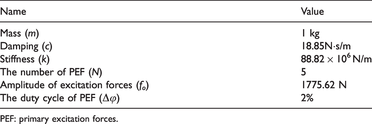
PEF: primary excitation forces.
The natural frequency of simulation blade is 1500 Hz. The vibration displacement of the blade under the above model parameters as shown in Figure 7, which shows all the synchronous vibration points that occur when the rotation frequency is 0–160Hz. Figure 8 shows the harmonic force amplitudes are calculated by equation (6) at all EO points, and the synchronous vibration points are a multiple of five uniformly distributed excitation forces.
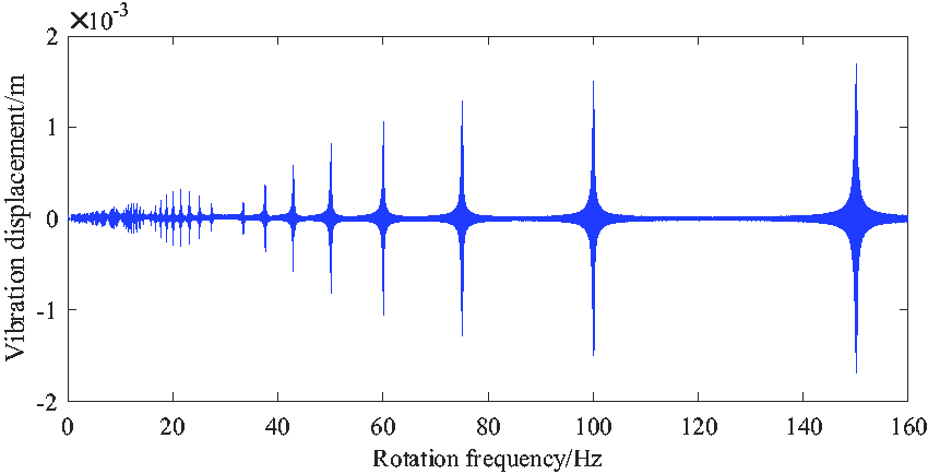
The blade vibration under 5 uniformly distributed excitation forces with duty cycle of 2%.
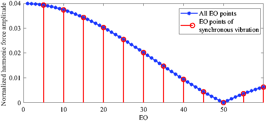
Variation of harmonic force amplitudes when synchronous vibration points occur.
By comparing Figures 7 and 8, it can be seen that the amplitudes of synchronous vibration decrease gradually when the value of EO is 5–60, which is consistent with the variation of the derived harmonic force amplitudes. The harmonic force amplitude of the synchronous vibration with the EO value of 50 in Figure 8 is 0. The changing trend of the harmonic force amplitudes when the value of EO is from 50 to 60 can also correspond to the synchronous vibration of rotor blade. This verifies that the derived equation of harmonic force amplitude is correct. In the following, the ASEF are introduced to control the synchronous vibration of rotor blade, and three control laws summarized in the section “Summary of synchronous vibration control laws by introducing ASEF” are verified.
Verification of the effect of ASEF on the original synchronous vibration of rotor blade
The influence of the number and position of ASEF on synchronous vibration control
On the basis of the above-mentioned PEF distribution, the introduction of ASEF parameters is shown in Table 2. When the number of ASEF is 3, there are two distribution modes as shown in Figure 9.
Parameters of ASEF.
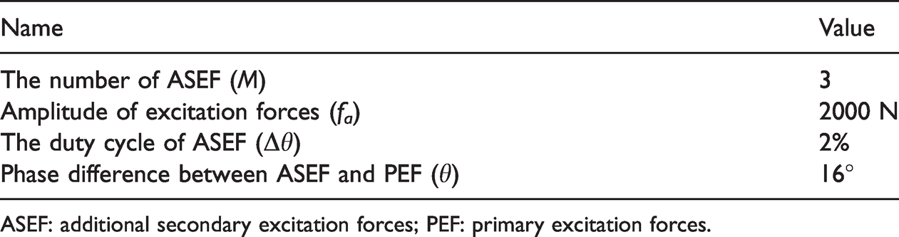
ASEF: additional secondary excitation forces; PEF: primary excitation forces.
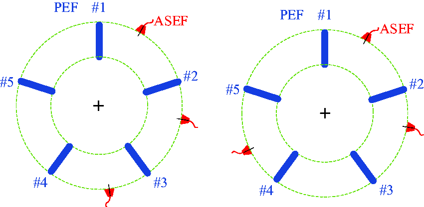
Two distribution modes.
The range of rotation frequency is from 145 Hz to 155 Hz to cover 150 Hz synchronous vibration point with the EO value of 10. Figure 10 shows the comparison of vibrations in the two distribution modes. For facilitate comparison, the envelope of vibration displacement is used. Through comparison, it can be known that different distribution position of ASEF will not affect the control effect of synchronous vibration when the number of ASEF is determined. Of course, this is an ideal state, but it’s applicable in general.
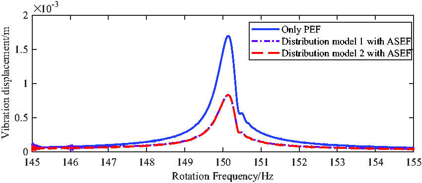
The blade vibration when the number of ASEF is the same and the distribution position is difference.
2. Periodic verification of ASEF for synchronous vibration control
In order to easy analysis, the peak-to-peak value of synchronous vibration displacement is used to evaluate the effect of vibration control. The number of ASEF introduced in the simulation is 4. Since the number of PEF is 5, the available position range of ASEF can be arranged is 0–72°.
It can be seen from Figure 11 that, after adding ASEF, the peak-to-peak value of blade at the synchronous vibration point changes periodically, and the number of cycles is 2. Combined with the periodicity of PEF distribution position, it can be known that the period number controlled by ASEF is consistent with the EO value of the synchronous vibration. The position of ASEF has a greater impact on the peak-to-peak value of the synchronous vibration of blade rotor, as shown in Figure 11. Choosing a suitable position can suppress the synchronous vibration. On the contrary, the vibration will be intensified when the position is not suitable.
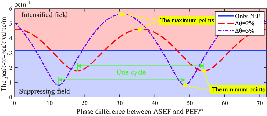
The influence of ASEF with different duty cycle on synchronous vibration amplitude of blade (EO = 10).
3. Verification of the effect of the direction of ASEF on synchronous vibration control
The number of ASEF is 4. The peak-to-peak value of synchronous vibration with the change of phase difference when the ASEF is added in the same direction and in the opposite direction.
The influence of ASEF in the same direction and in the opposite direction on the synchronous vibration of rotor blade is different in half a period, as shown in Figure 12. Therefore, the ASEF can be introduced in the same direction or in the opposite direction, which can achieve the same synchronous vibration control effect.
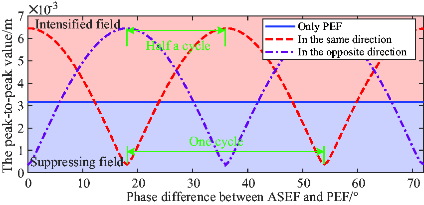
Effect of adding ASEF in the same direction and opposite direction on synchronous vibration control of blade (EO = 10).
The influence on synchronous vibration control when the excitation forces have amplitude and angle error
A certain amount of white noise is added to the PRPWF to simulate the instability of the force amplitude in simulation model. The phase difference between ASEF and PEF has no error when simulating the effect of force amplitude fluctuation on synchronous vibration control. Figure 13 shows a comparison of synchronous vibration with and without noise, where the signal-to-noise ratio (SNR) of the amplitude of PEF and ASEF are both 1.
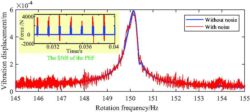
Synchronous vibration of blade with or without noise.
It can be concluded from Figure 13 that the influence on the vibration amplitude and the control effect at the synchronous vibration point is small when the SNR of PEF and ASEF are both 1. That is to say, the PRPWF can be used to approximately analyze the synchronous vibration and achieve the synchronous vibration control of rotor blade.
Monte Carlo method has been used to simulate the influence of excitation forces angle error on synchronous vibration control. Since the simulation results are relatively close, three representative examples are selected to show. The angle errors of excitation forces include those caused by the nonuniformity of PEF, and measurement and installation between ASEF and PEF. Figure 14 shows the vibration at the synchronous vibration point with the same ASEF parameters under three kinds of the angle error. Figure 14(a) shows the PEF installation angle errors with the same sign, which are respectively 0°, 2°, 4°, 5°, 7°. Figure 14(b) shows the fluctuation of the installation angle errors of PEF, respectively 0°, 2°, −4°, −3°, −1°. Figure 14(c) shows when the installation angle errors of PEF and ASEF are both fluctuating.
Vibration comparison of PEF and ASEF with or without installation angle error.(a) The PEF installation angle errors with the same sign (b) The fluctuation of the installation angle errors of PEF (c) The installation angle errors of PEF and ASEF are both fluctuating.
From the analysis in Figure 14, it can be seen, when the installation angle errors of excitation forces are the same sign, that it will have a great impact on the mounting position of ASEF which suppresses the synchronous vibration, but will have a small impact on the amplitude of synchronous vibration control. When the installation angel errors fluctuate around the accurate value, the influence on synchronous vibration is small. Therefore, a slight installation angle error can be allowed in the actual synchronous vibration control of rotor blade, which will not lead to the opposite control result of the synchronous vibration.
Experimental analysis
The synchronous vibration control experiment of rotor blade was carried out on the high-speed straight blade test bench.24,25 The excitation forces are generated by permanent magnets uniformly mounted on the cover, as shown in Figure 15. In the experiment, the ASEF are added to fixed PEF to explore the influence on the original synchronous vibration.
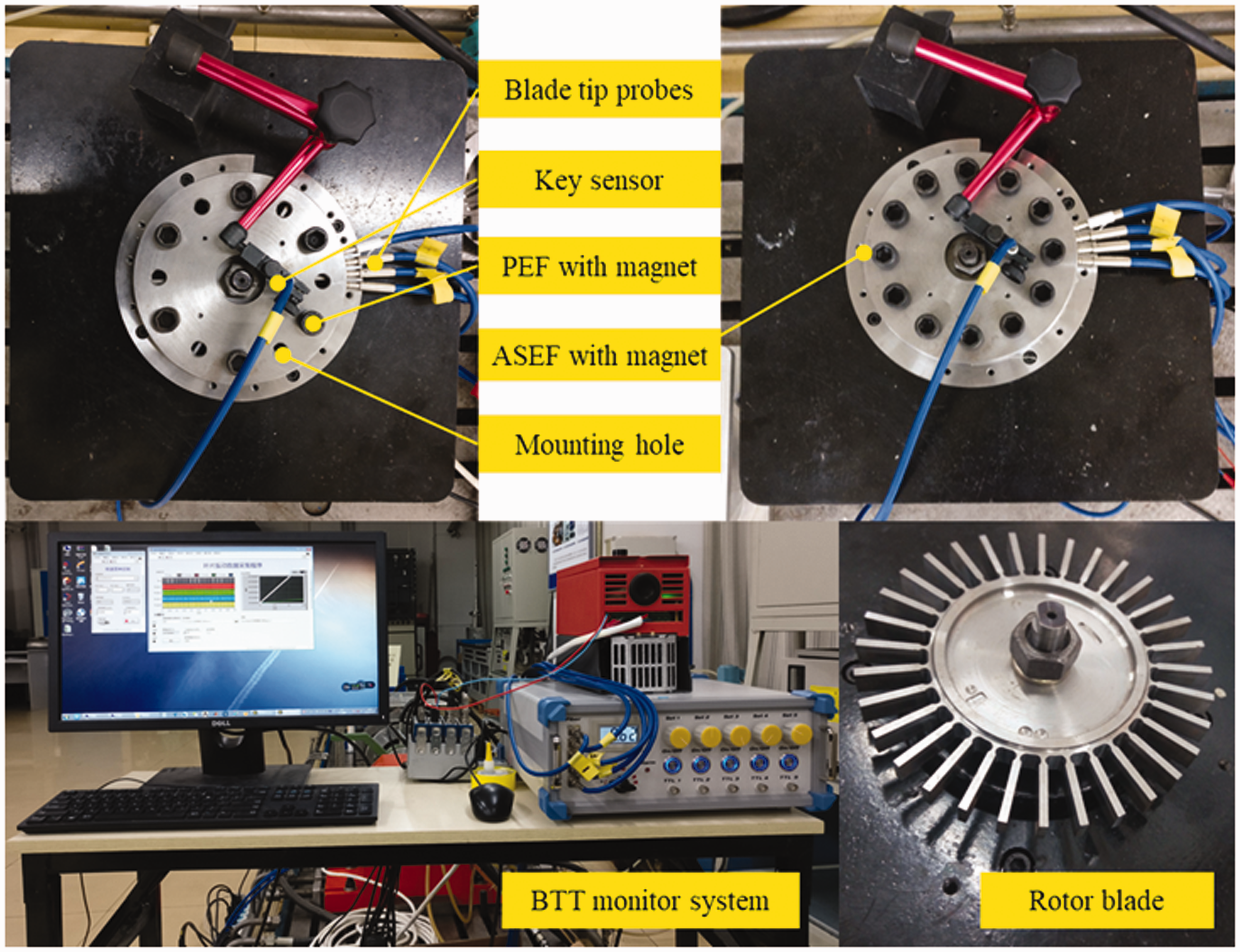
High-speed straight blade test bench with 6 PEF and 6 ASEF.
Figure 16 shows the vibration displacement of one blade measured by blade tip-timing (BTT) system when the number of PEF is 6, and the blade vibration displacement after adding 6 ASEF to the 6 PEF. The phase difference between the ASEF and PEF is 30°, and other parameters of ASEF are the same as the PEF. When there are only 6 PEF, there are four obvious synchronous vibration points, which are marked with circles, as shown in Figure 16. After adding 6 ASEF, the synchronous vibration of the same blade has changed. For example, the vibration amplitudes at the rotation frequency 63.01 Hz and 94.59 Hz increase significantly, and the vibration amplitudes at the rotation frequency 75.63 Hz and 126.3 Hz weaken, even disappear. It can be seen that the introduction of ASEF can increase some synchronous vibration points, and can also suppress some synchronous vibration points, which depend on the mounting position of ASEF. It simply proves that the control of synchronous vibration can be achieved by adding ASEF.
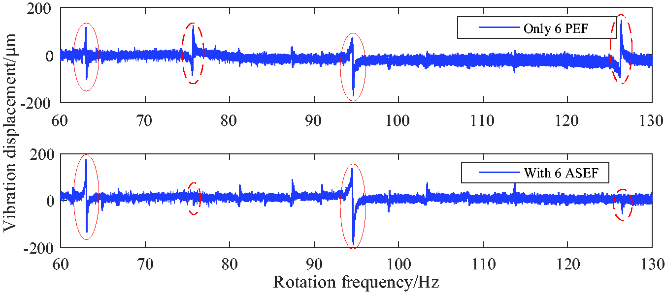
Comparison of vibration displacement with 6 ASEF on the basis of 6 PEF.
Combining with the previously explored knowledge of the blade synchronous vibration parameter identification, 24 the obvious synchronous vibration points in Figure 16 can be analyzed to obtain the vibration parameters, as shown in Table 3.
Synchronous vibration parameters of blade before and after introducing ASEF.
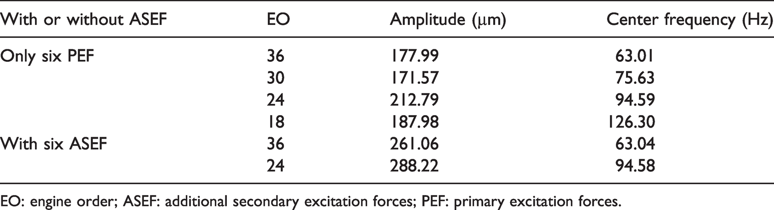
EO: engine order; ASEF: additional secondary excitation forces; PEF: primary excitation forces.
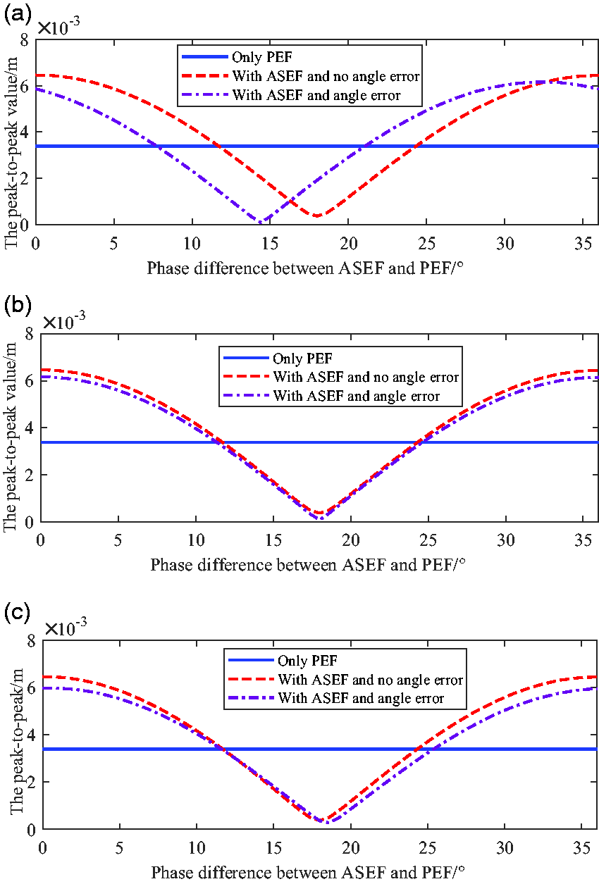
Using equations (11) and (12) in the theoretical derivation can analysis the vibration in the case of only 6 PEF and adding 6 ASEF, as shown in Figure 17. When the phase difference between the ASEF and PEF is 30°, the vibration amplitudes of the blade are close 0 when the values of EO are 18 and 30, and the synchronous vibration is completely suppressed. When the values of EO are 24 and 36, the peak-to-peak values of the synchronous vibration of the blade are doubled.
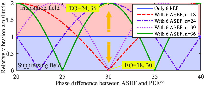
The synchronous vibration amplitudes of PEF and ASEF with different EO and different interval phase under the simulation.
It can be seen from Figure 17 that the vibration amplitudes of synchronous vibration with the EO value at 24 and 36 after the introduction of 6 ASEF should be twice as much as that of 6 PEF. But the vibration amplitudes obtained through parameter analysis in Table 3 are not doubled, which shows that the vibration amplitude increases more after adding ASEF, and the trend conforms to the theoretical derivation. This may be due to a certain error in the amplitude of synchronous vibration obtained by curve fitting. Due to the nonuniformity of excitation forces, error caused by installation, etc. may also lead to a nonstrict double relationship.
The experimental data verifies the correctness of the theoretical deduction and analysis, and the synchronous vibration control of rotor blade can be achieved by introducing ASEF. The disadvantage is that due to the design limitation of the test bench, only the excitation force at a fixed point can be added. In the follow-up work, a test bench can be built with an adjustable installation angle of excitation force to achieve continuous control of the synchronous vibration of rotor blade. And it is used to further explore the vibration suppression of rotor blade synchronous vibration.
Active suppression strategy for synchronous vibration of rotor blade
According to equation (11), the harmonic force amplitude of the synchronous vibration of rotor blade is determined by the parameters of PEF and ASEF, and the value of EO. In general, the PEF on rotor blade are unknown and changeable in the whole operation condition, but the parameters of PEF are fixed at a certain synchronous vibration point. How to introduce and control ASEF is very important to the blade synchronous vibration control. By analyzing the controllable parameters of ASEF, in can be known that control effect is determined by the total force coefficient of the excitation forces, the duration and the position of ASEF. Generally, the duration of ASEF is unknown, so the controllable parameters of ASEF are only the total force coefficient of the excitation forces and the mounting position. Equations (12) and (13) provide us with the idea of synchronous vibration suppression strategy.
It can be seen from equation (12) that for unknown PEF, changing the mounting position of ASEF can find the optimal position with the smallest amplitude of the synchronous vibration. According to equation (13), when the optimal mounting position is known, the optimal value of the total force coefficient of the excitation forces can be found by changing the amplitude of ASEF to find the optimal force.
The flow chart of active suppression of synchronous vibration by adding ASEF is as shown in Figure 18. According to equation (12), in order to obtain the optimal position, the amplitude of ASEF cannot be 0. So a certain value of ASEF should be given to judge the optimal position and make the vibration change obviously. Then, the amplitude of ASEF is gradually increased on the basis of determining the optimal position to seek the optimal amplitude of ASEF.
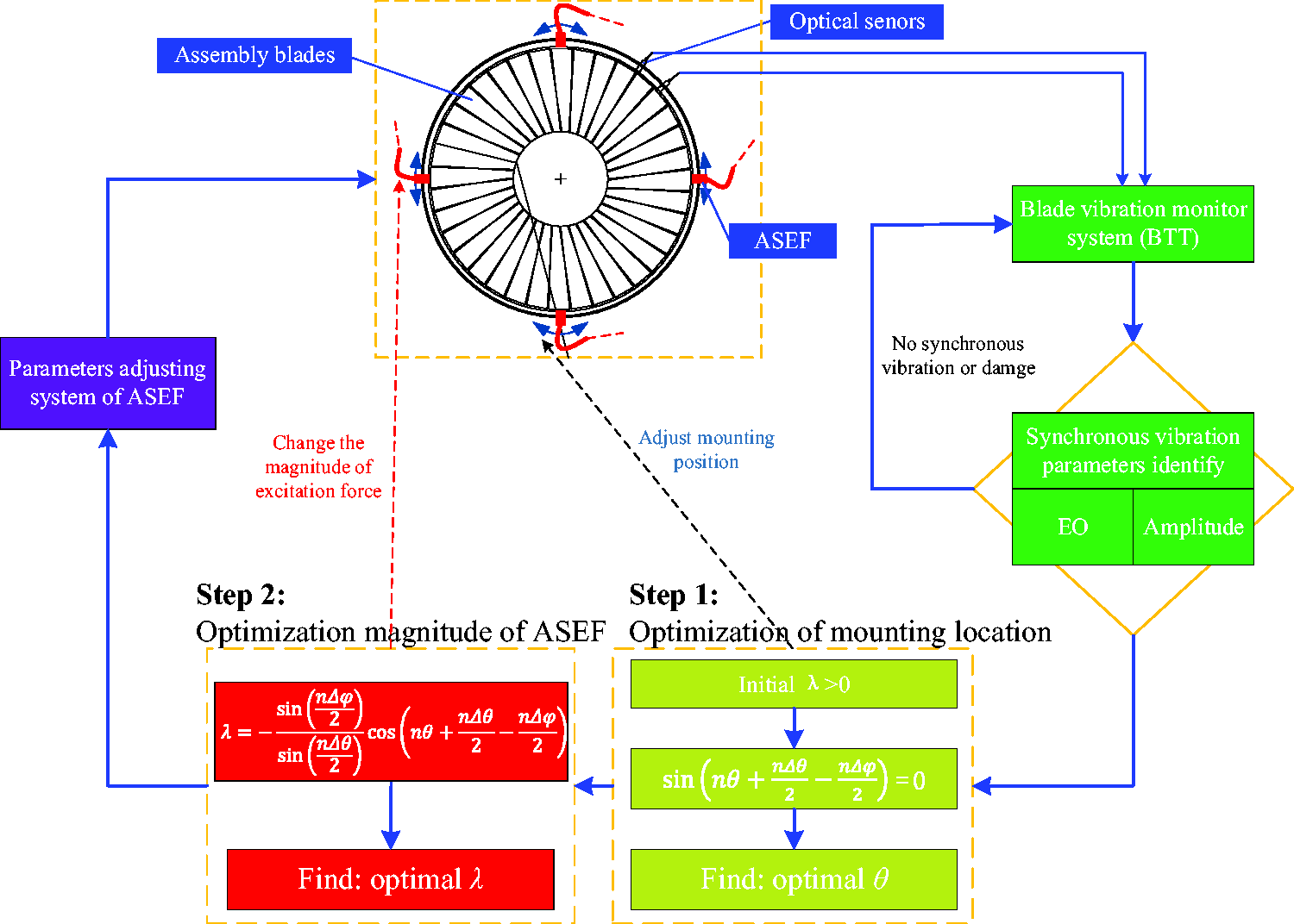
Flow chart of suppression strategy of synchronous vibration of rotor blade based on ASEF.
In the process of implementation, it is necessary to judge whether the synchronous vibration occurs or not through the blade vibration monitoring system. At the same time, it is necessary to judge whether the synchronous vibration will harm the rotor blade. If it is harmful, the suppression strategy needs to be activated.
Conclusions
This paper analyzes the excitation forces that cause synchronous vibration of rotor blade, and derives the synchronous vibration laws of rotor blade under the condition of uniform excitation forces by simplifying it into the form of PRPWF. The method of introducing ASEF is proposed to control the synchronous vibration of rotor blade caused by PEF. The ASEF are defined, and the detailed derivation and control laws are given. The control laws of synchronous vibration of rotor blade by introducing ASEF are as follows: When the number of ASEF is fixed, the different distribution positions of ASEF will not affect the control effect of synchronous vibration. The phase difference between ASEF and PEF has a periodic relationship with the peak-to-peak value of the synchronous vibration after controlling, and the number of cycles is the value of EO of the synchronous vibration. When the ASEF are used to control the synchronous vibration of rotor blade, the same control effect can be achieved by applying ASEF in the same direction or in the opposite direction with PEF, but the difference between them is half a cycle. The amplitude error of the excitation forces has a small influence on the synchronous vibration control of rotor blade. When the installation angle and the duration of the excitation force are fluctuating, the effect of the synchronous vibration control is also small.
Through the above control laws, the synchronous vibration control of rotor blade can be realized by introducing ASEF.
On the straight blade test bench, 6 ASEF are introduced on the basis of 6 uniformly distributed PEF, which achieves vibration suppression at the EO values of 18 and 30, and the vibration increases at the EO value of 24 and 36. The experiment results are consistent with the theoretical derivation.
Finally, the suppression strategy of synchronous vibration of rotor blade by introducing ASEF is given.
Footnotes
Declaration of conflicting interests
The author(s) declared no potential conflicts of interest with respect to the research, authorship, and/or publication of this article.
Funding
The author(s) disclosed receipt of the following financial support for the research, authorship, and/or publication of this article:This work has been carried out with the supports of the National Key Research and Development Program of China (No.2016YFB0901402) and the Major Program of National Natural Science Foundation of China (Grant No. 51790513). The author(s) would like to thank them for funding it and their permission to publish the paper.