
Abstract
The paper aims at evaluating the sliding mode control parameters used to tune a dynamic damper in the vibration reduction system. The effectiveness of the presented vibration reduction system and the power of the controlled voltage source supplying an electrodynamic linear motor have been analysed. The classical sliding mode control algorithm has been modified based on the analyses of results of calculation. The operation of the modified algorithm has been checked during a simulation. The proposed vibration reduction system was implemented on a laboratory stand. The measurement results have confirmed the effectiveness of the considered system.
Introduction
The antiresonance phenomenon in mechanical systems was used to design mass dampers. Such a damper was proposed by Den Hartog in the 1920s. Many damper types have appeared since then, both simple1–4 naturally introducing the antiresonance to vibroisolated systems, and with control subsystems.5–7 Vibration reduction systems with mass dampers are used in building structures such as tall buildings, masts, towers, bridges, sport arenas and in various machines to reduce the vibration of their subsystems. Many building structures have mass damper systems to protect them against seismic actions and strong winds. One of the best known examples of use of such a system is the vibration reduction system in a high-rise building in Taipei in Taiwan.
The effectiveness of classic mass dampers is significantly limited. The dampers require a precise tuning which involves a suitable determination of the spring stiffness coefficient and the viscous damping coefficient in relation to the damper mass. The design of the damper should be preceded by the modal analysis of structure and the spectral analysis of excitation. The structure parameters can, however, change during the structure operation, and then the damping effectiveness is reduced even at small changes. Therefore, in many cases it is desirable to use more complex vibration reduction systems which, based on the mass damper design, can adjust the damper force acting on the vibroisolated substructure depending on change of the excitation and possible changes of the structure parameters. The use of an additional control system can have a beneficial influence on the vibration reduction effectiveness and, as a result, such effectiveness will be much higher than for classic mass dampers.8–10
The effectiveness of a reduction system with a controlled mass damper depends on the proposed algorithm and possibilities of its technical application in the construction of a reduction system. The literature includes descriptions of a number of control algorithms used to reduce vibration. Some of them are generally known control methods, and others are dedicated especially for vibration reduction systems. The aim of the paper is to propose new methodologies based on sliding mode control for control vibration reduction systems designed with the use of mass dampers.
Literature in the field of sliding mode control contains a number of complex algorithms.11–15 In general, the authors of these articles present theoretical considerations and computer simulations. It can be observed that the correct operation of the proposed methods depends on a precise description of the object’s state, immediate reaction of the actuators and often relatively large values of the control signal, which is associated with a significant increase in energy consumption. The energy consumption is not generally the subject of the authors’ considerations. In vibration reduction systems using mass dampers, the control signal is the force acting on the protected system and simultaneously on the mass of the damper. The mass movement must be taken into account at any time during the operation of the vibration reduction system, which is an additional limitation for the operation of the sliding control algorithm.
The proposed active vibration reduction system (AVRD) considerably extends the possibilities of classic mass dampers. This was possible due to the use of a modified sliding mode control algorithm. Bearing in mind the nature of the mass damper operation, a component limiting the displacement of the damper mass was introduced into the control algorithm. In addition, the original method of gain adaptation was proposed; the method ensures a special adaptation of the gain in such a way that its value is as small as possible and sufficient to counteract the perturbation. Thanks to the algorithm used, the level of chattering and energy consumption have been reduced. The proposed active reduction system has been tested in a laboratory stand. The results of numerical simulations and the results of the experiments were compared.
Laboratory facility
In civil engineering, dynamic dampers have found application in slender structures such as towers, masts, chimneys and high-rise buildings, for which vibrations are particularly dangerous. A laboratory stand was designed to analyse the vibrations of such structures and test the proposed vibration reduction systems. The main part of the laboratory station is a model of a telecommunication mast (Figure 1). The tests performed on the station can be generalised for most slender structures, both qualitatively and in many cases also quantitatively. 21
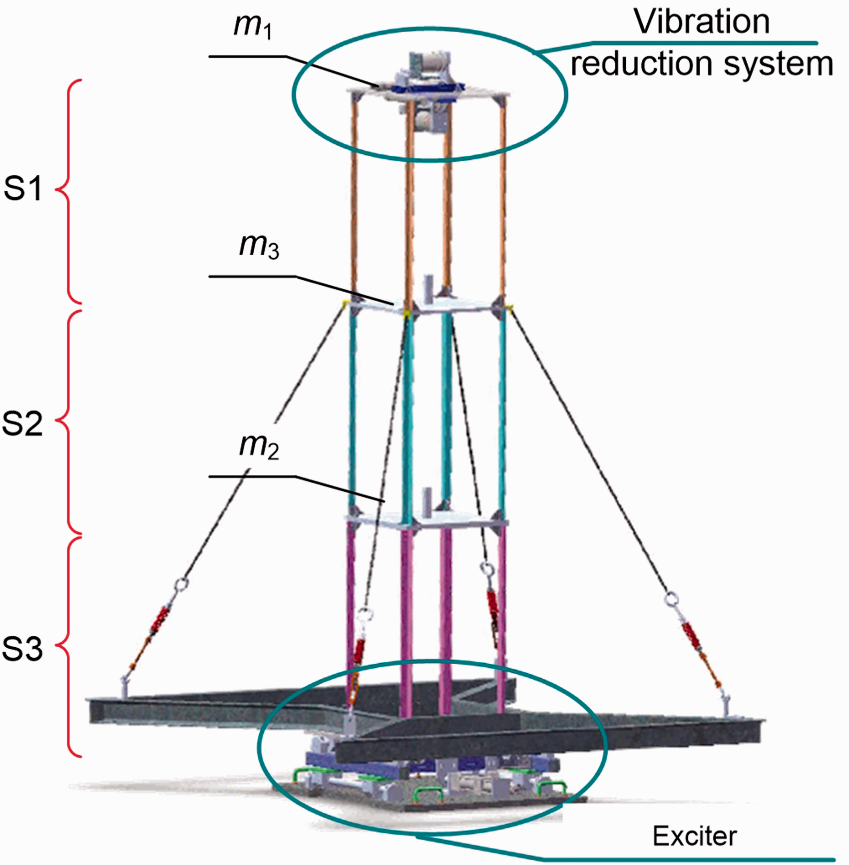
Laboratory mast model.
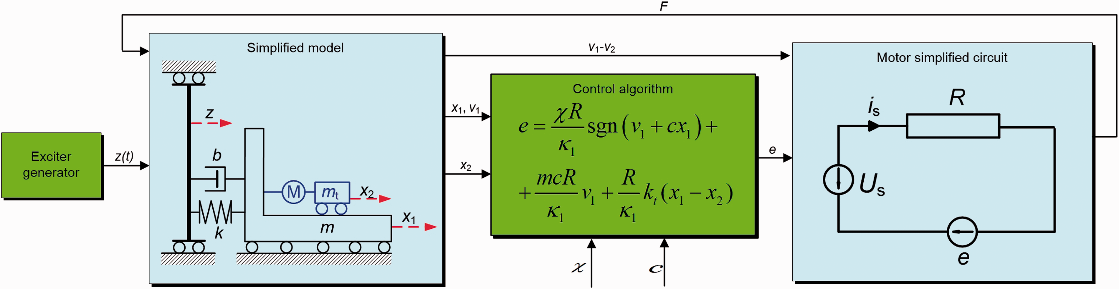
The laboratory mast model shown in Figure 1 consists of three segments S1, S2 and S3. As in the real system, the model has three platforms of mass m1, m2 and m3. In the model they are connected with aluminium elements. The structure is reinforced with four, symmetrically placed stays.16,17 The slender structure model is fastened to the moving part of an electrohydraulic exciter. The vibration reduction system is placed on the platform of mass m1. The design of the system is typical for mass dampers. 17 The mass of the damper is connected with a vibroisolated subsystem by means of an electrodynamic motor. The control subsystem controls the motor in such a manner as to minimise the top platform vibration at an acceptable increase of the damper mass displacement. The vibration reduction system is presented in Figure 2(a). The electrical circuit of the vibration reduction system that includes the power supply system of an electrodynamic linear motor is shown in Figure 2(b). The calculations and measurements were limited to displacements of vibroisolated platform x1 and the damper mass x2. The motion of the remaining structure part was simplified, modelling it by means of kinematic excitation z(t) acting on the vibroisolated platform through an elastic-damping connection.
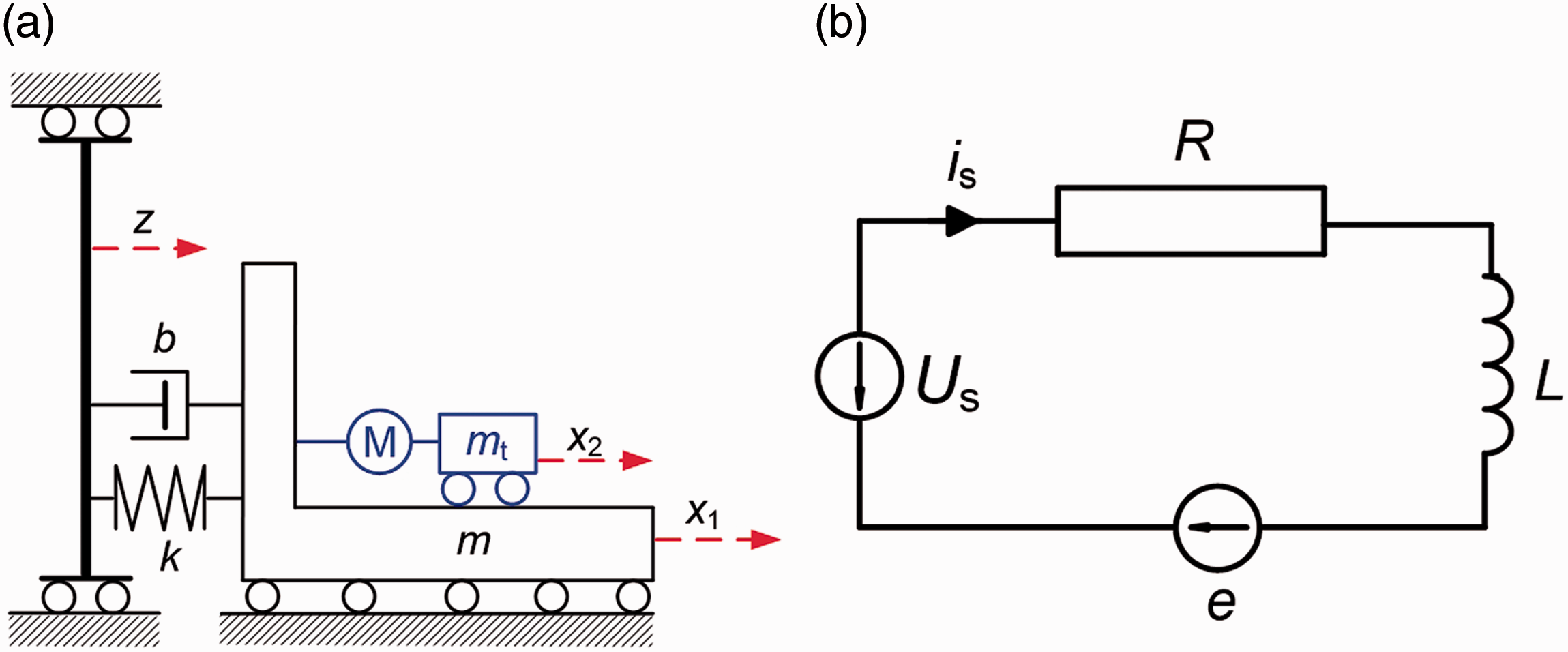
(a) Mechanical system diagram and (b) linear motor electrical circuit.
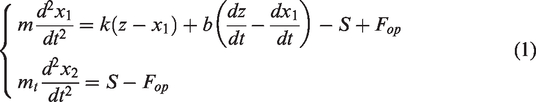
The motion equations of the vibroisolated platform and the damper mass are as follows
Application of the sliding mode control algorithm
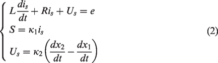
The aim of the vibration reduction system is to reduce the platform displacement amplitude. The forces generated by the vibration reduction system should compensate for the forces applied by the mast to the platform. Taking into account that inductance L is small, the state equations of a vibroisolated platform can be written as
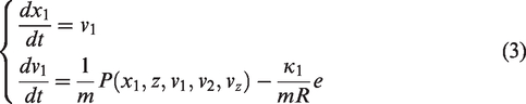
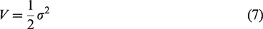
In the system of equation (3), P is the force disturbing the equilibrium position of the platform

According to the principles regarding the sliding mode control algorithm,18 the sliding variable σ was defined as a linear combination of state variables

Equating the sliding variable to zero, one can obtain an equation that describes the sliding surface in the state space

The measure of distance of actual state trajectory to the sliding surface is the Lyapunov function
The state trajectory will approach the sliding surface if the Lyapunov function derivative along the state trajectory is negative (
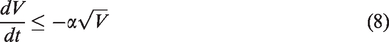
The basis for the control signal determination is an inequality limiting the Lyapunov function derivative along the state trajectory

In the calculations the following substitution was used


The influence of the control algorithm parameters on the efficiency of the vibration reduction system
The control algorithm proposed in the previous section was analysed and subjected to simulation tests in order to determine if the values of parameters
The following data obtained based on the identification of the studied system were used in the calculations:
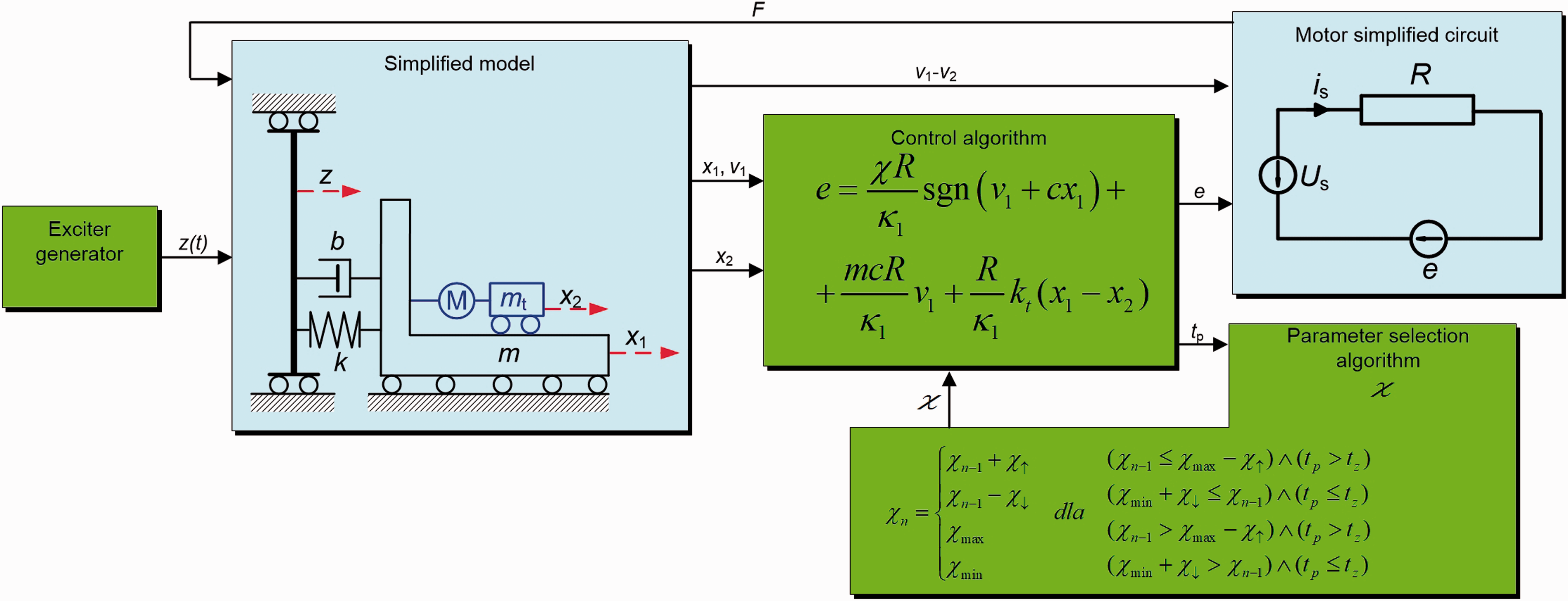
Block diagram with the control algorithm.
The first simulation was performed for a passive model obtained as a result of a short circuit in the motor circuit and disconnecting an external source. Assuming a sinusoidal-changing excitation z(t) of a constant amplitude Az and slowly increasing frequency, the characteristics described by coefficients w1=A1/Az and w2= A2/Az (Figure 4) were determined. Symbols A1, A2 and Az denote amplitudes of displacement signals x1, x2 and z.
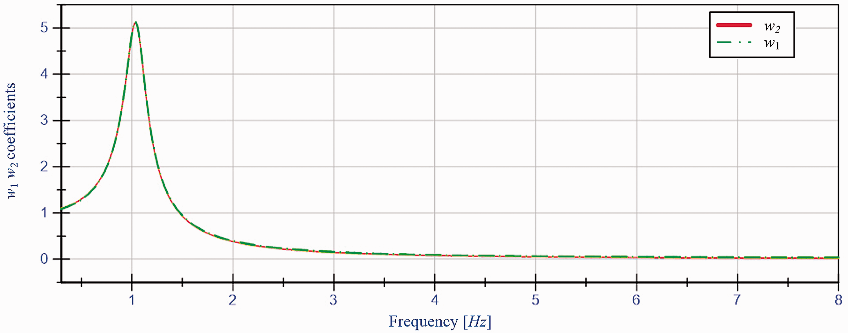
Vibration transmission coefficients w1, w2 for a passive system.
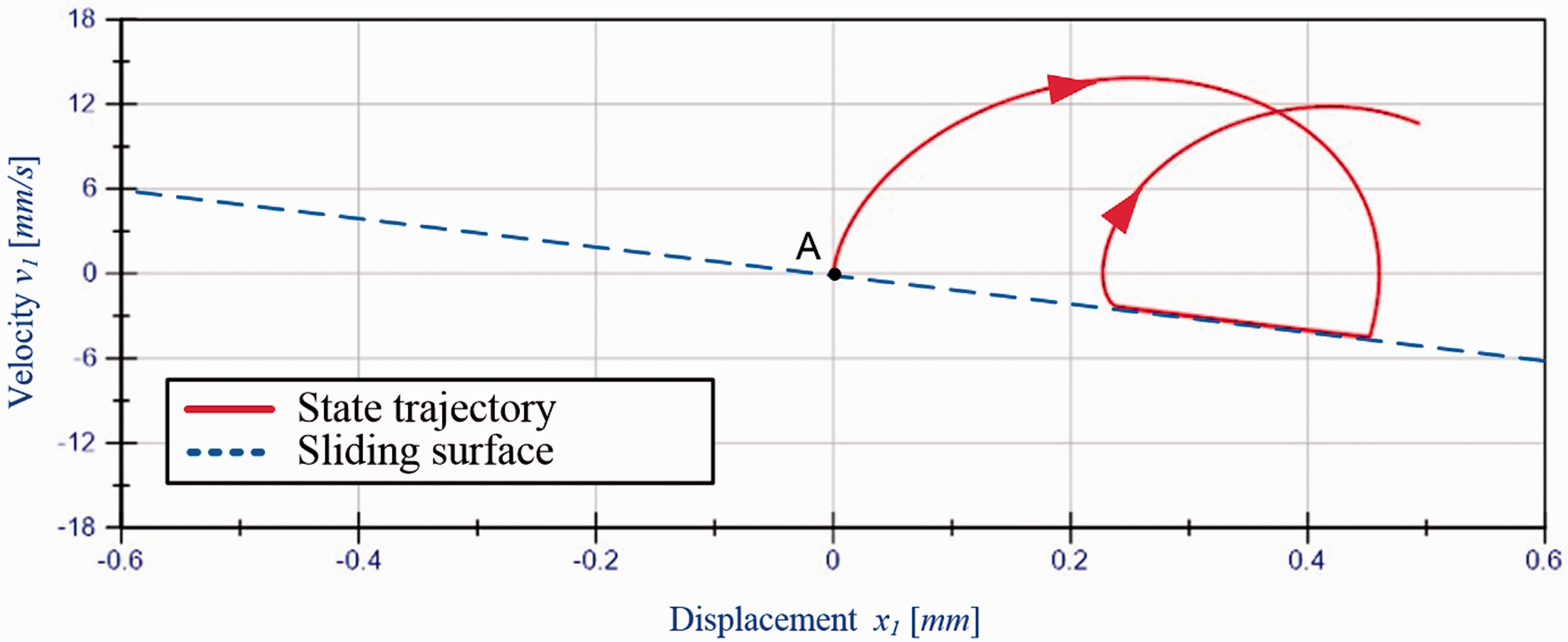
The correct action of the proposed sliding mode control algorithm can be verified by analysing the state trajectories of a platform after it has been knocked out from the equilibrium position. The simulation results for parameters c = 10 s−1 and χ = 30 N are presented in Figure 5. The simulations were performed for a sinusoidal-changing excitation z(t) of an amplitude equal to 1 mm and frequency of 8 Hz.
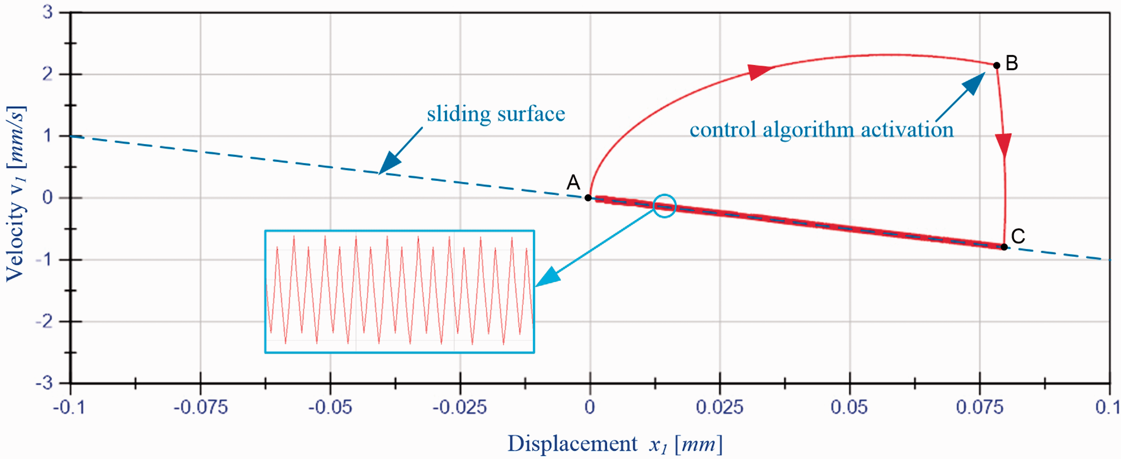
Platform state trajectory.
The AB part of the state trajectory represents the platform motion when the vibration reduction system is off. When the system is activated (point B), the platform trajectory is changed according to the sliding mode control. In the first phase of control, the trajectory (BC part) approaches the assumed sliding surface. In the intersection point of the trajectory and the sliding surface, the sign of the sliding variable
The simulations indicate that the algorithm performs correctly for all the analysed excitation frequencies. The algorithm effectiveness depends on the motor displacement limit and on the assumed parameters
The studies of the influence of the reduction system parameters on the coefficients
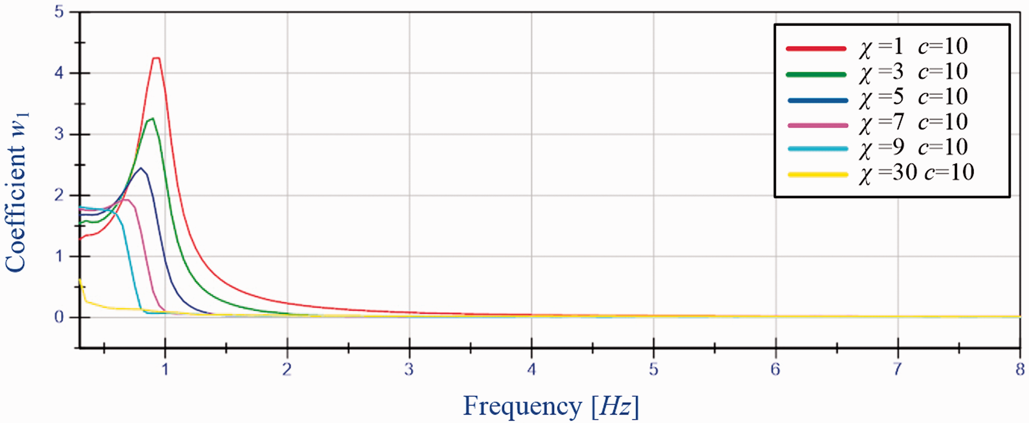
Coefficient w1 as a function of excitation frequency at constant c = 10 s−1 and for various χ.
The simulation results were elaborated for a sinusoidal-changing excitation of amplitude 1 mm and parameter c = 10 s−1. A comparison of the received results and the results presented in Figure 4 indicates that the proposed algorithm allows the substantial reduction of vibration for all used values of
A result of the change of parameter
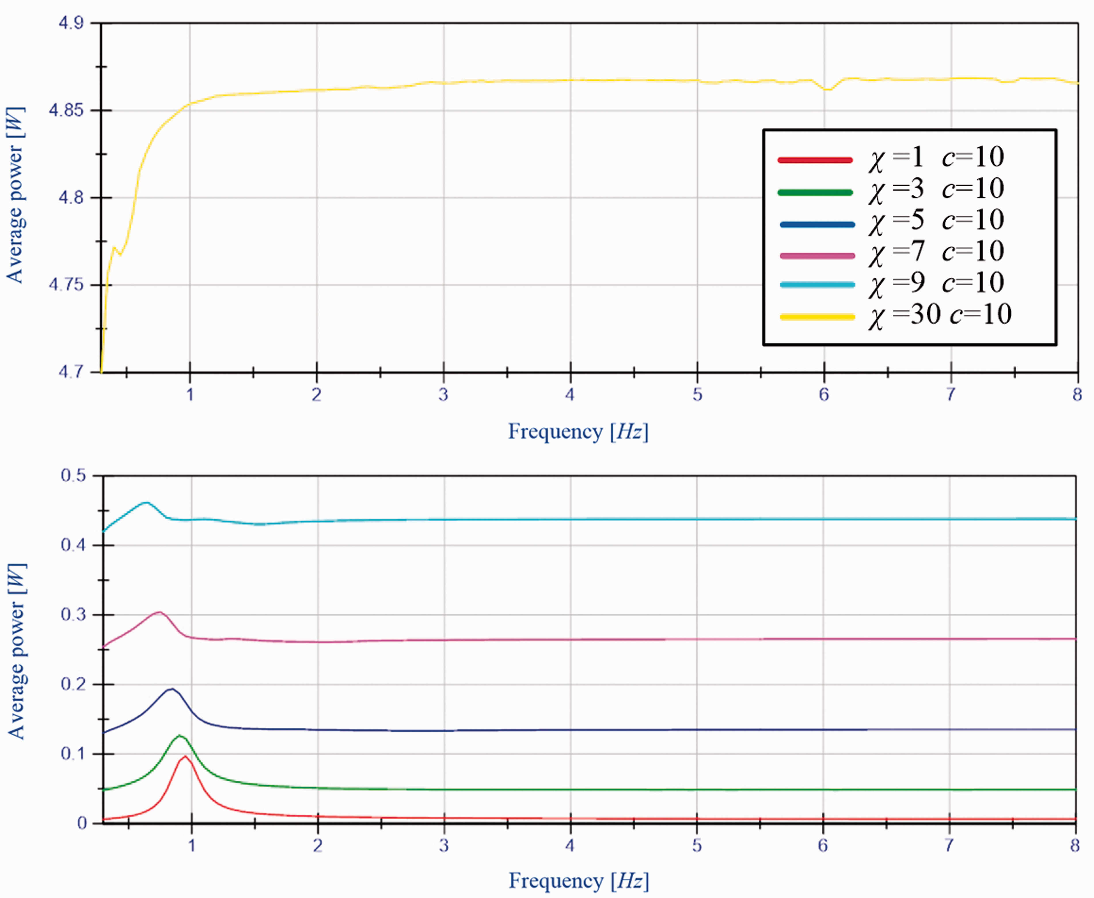
Average power as a function of excitation frequency at constant c = 10 s−1 and for various values of χ.
The determined average power depends significantly on the values of coefficient
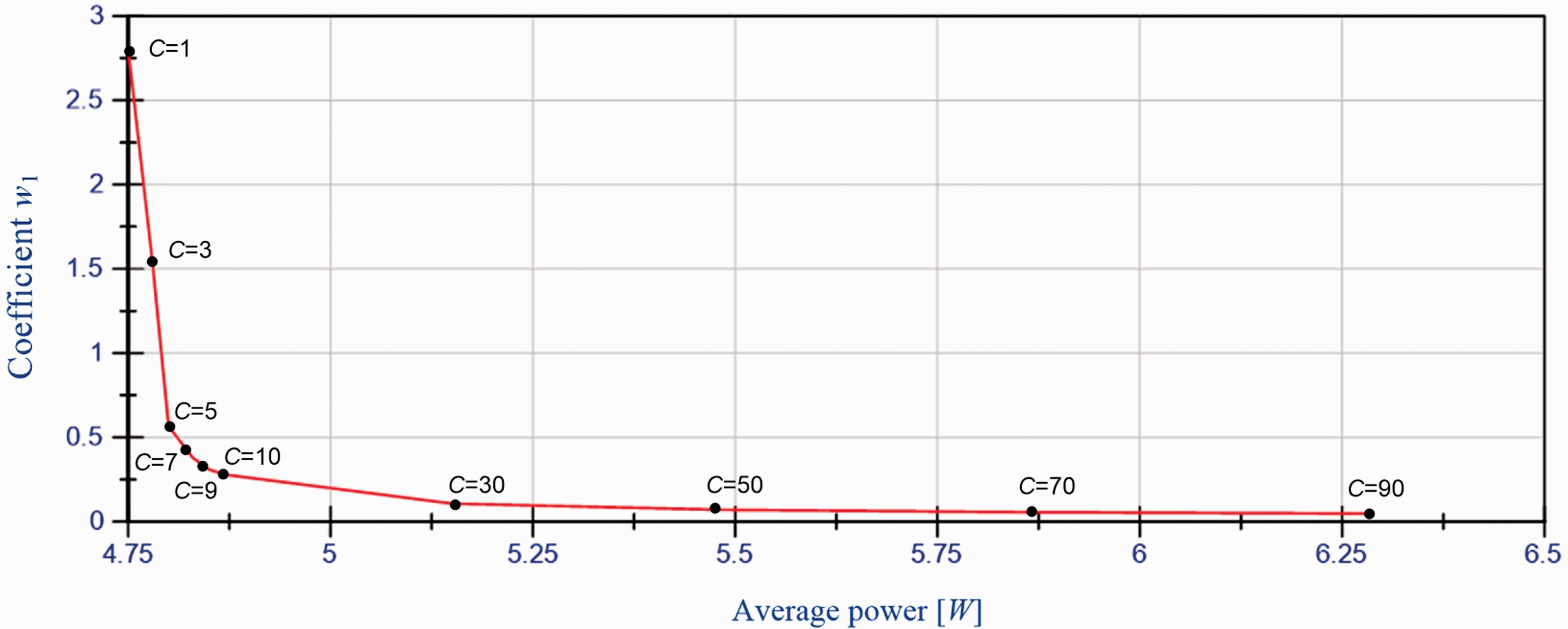
The relation between the maximum value of coefficient
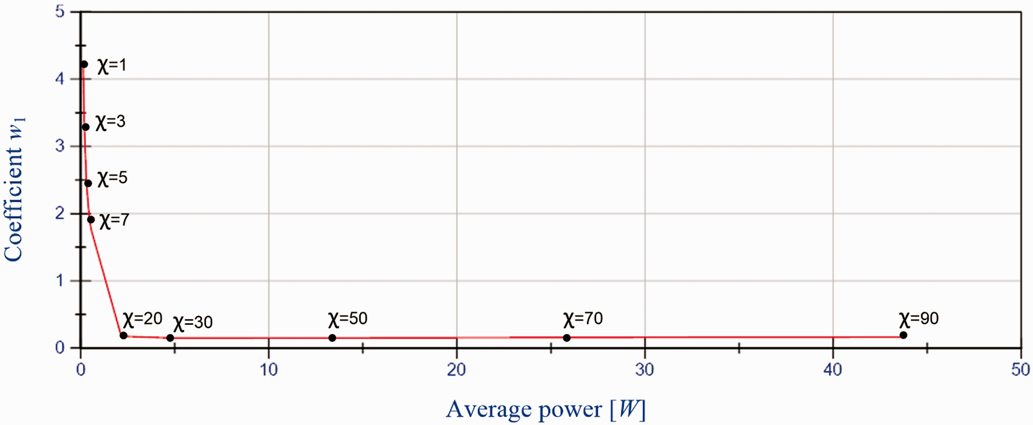
Maximum value of the coefficient w1 in relation to maximum average power determined for various parameters χ at constant c = 10 s−1.
The influence of the sliding surface inclination c on the coefficient
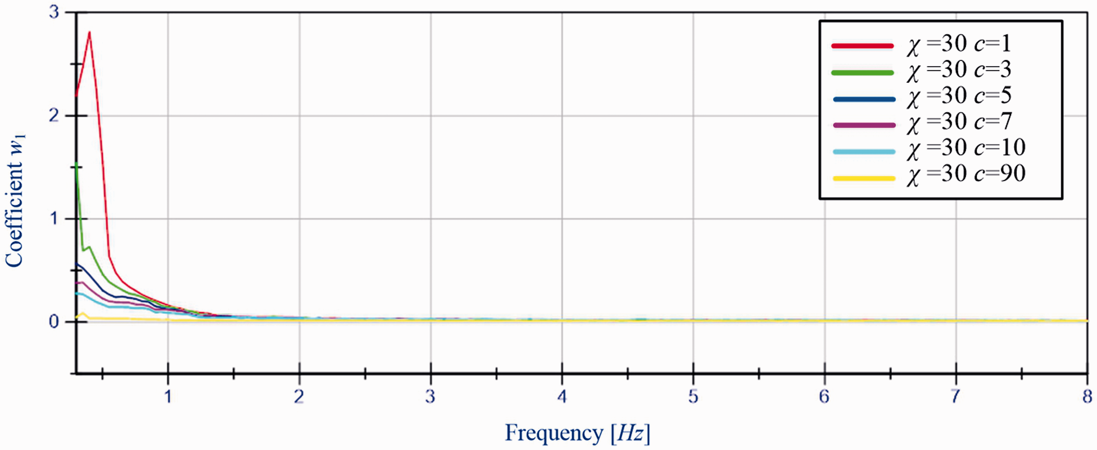
Coefficient w1 as a function of excitation frequency at constant χ = 30 N and various c.
The analysis of the simulation results indicates that an increase of the sliding surface inclination for low excitation frequencies has a favourable influence on the reduction of vibration of the platform. For higher excitation frequencies, the change of parameter c does not significantly affect coefficient w1.
The influence of changing the parameter c on the electric power is shown in Figure 10.
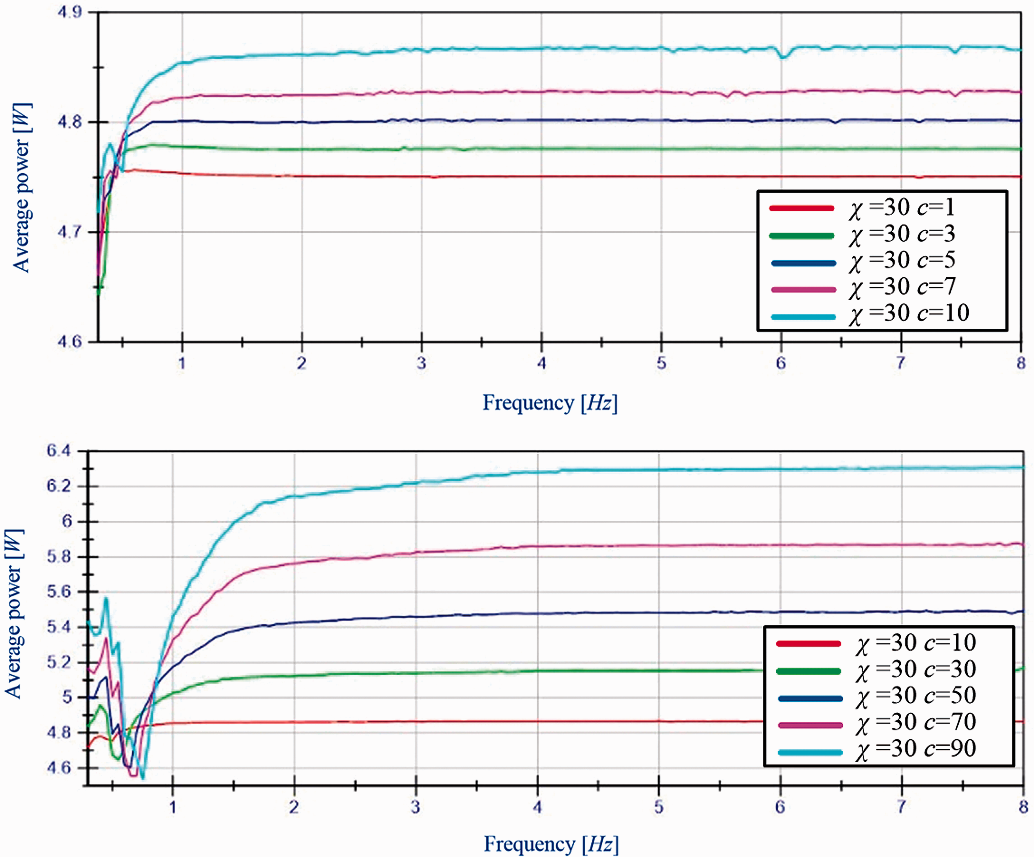
Average power as a function of excitation frequency at constant χ = 30 N and various c.
The analysis of the results indicates that an increase of parameter c increases the average power for excitation frequencies above and below the resonance frequency. In addition, while comparing the results for other combinations of parameters c and
An analysis of the dependence between the coefficient w1 and the average energy consumption was carried out in order to evaluate the influence of changing the sliding surface inclination on the effectiveness of the vibration reduction system (Figure 11). The results are presented for various c, at constant χ = 30 N and for sinusoidal-changing excitation signal of frequency 0.3 Hz and amplitude Az=1 mm.
Maximum value of the coefficient w1 in relation to average power, determined for various c at constant χ = 30 N.
The analysis of the results indicates that the recommended effectiveness is achieved at c ≈ 10 s−1. A further increase of c raises the average power and not significantly improves the efficiency of the vibration reduction system.
The studies indicate that the proposed sliding mode control algorithm is correct for any combinations of parameters
Choice of gain
Modification of the classical sliding mode control algorithm
The simulations presented in previous section indicate that from an effectiveness perspective, it is important to choose the proper gain
Platform state trajectory.
For t < 0.1 s, the platform state trajectory is in a small vicinity of point A, the gain is correctly chosen. When the disturbance amplitude increases, the platform state trajectory moves away from the vicinity of point A. The control algorithm is not able to supply a sufficient amount of energy at each moment, hence the result of its operation is only a temporary maintenance of the trajectory within the vicinity of the sliding surface, after which the trajectory again moves away from the sliding surface.
Chattering is a result of frequent change of sign described by the expression
The proposed modification of the sliding mode control algorithm involves dynamical adaptation of the coefficient
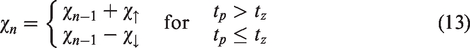
Equation (13) describes the gain coefficient in recursive form. Indexes
A practical implementation of the algorithm requires the introduction of limitations of the coefficient
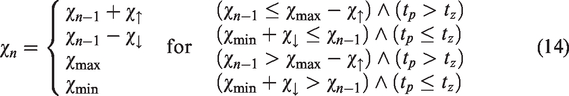
The control algorithm presented in Figure 3 was supplemented with determination of the parameter
Block diagram with the modified control algorithm.
In simulations, the disturbance was assumed in the form of a sinusoidal signal with a frequency of 2 Hz. The signal, as shown in Figure 14(a), was generated for two values of amplitude: 1 mm in time interval 0 ≤ t < 15 s, and 2 mm for t ≥ 15 s.
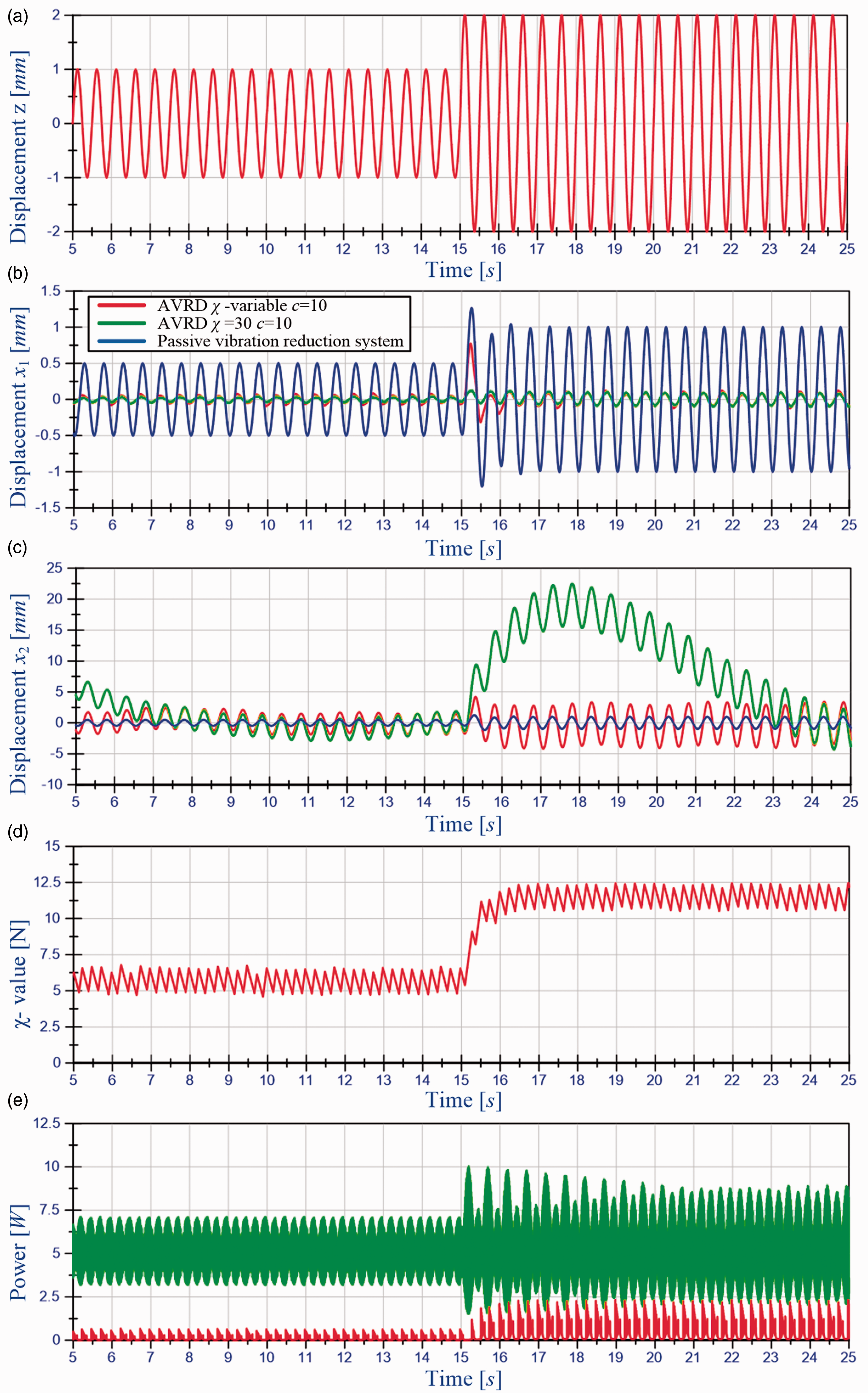
Time waveforms (a) excitation z(t), (b) platform displacement x1(t), (c) damper mass displacement x2(t), (d) χ-value and (e) power.
The generated disturbance signal was used to test the proposed algorithm. The parameters of the tested algorithm were as follows:
The analysis of the obtained results indicates that the operation of the proposed AVRD causes a significant reduction of the platform vibrations in relation to the passive reduction system. The comparison of AVRD controlled by the constant-parameters algorithm and the AVRD controlled by adaptive algorithm indicates that the first of them shows higher energy consumption and it is slightly more effective in reducing of platform displacement x1.
The difference in the operation of two active reduction systems is evident when the amplitude of the disturbance increases to 2 mm. The system with fixed parameters reacts faster, preventing a significant increase in displacement of the vibroisolated platform. Such a reaction of the vibration reduction system is associated with an increase of force, which causes an increase in the damper mass displacement. The vibration reduction system with adaptive algorithm reduces the displacement of the vibroisolated platform less effectively because the adaptation to the disturbance with smaller amplitude (1 mm) caused a reduction of the gain coefficient to 6 N. Of course, the lower force exerted by the vibration reduction system does not significantly change the movement of damper mass. After several periods, both vibration reduction systems determine the displacement of the vibroisolated platform at a similar level. The adaptive algorithm increases the gain coefficient to 12 N.
Taking into account the energy consumption and speed of adaptation to varying excitation conditions, the modified algorithm allows for a more effective and economical operation of the vibration reduction system.
Verification test
The proposed control algorithm was tested on the laboratory station shown in Figure 15 and described in Górski et al. 20 The station consists of a frame with elements to install the measuring instruments (4), three platforms (2, 6, 10) and a set of springs (5). The exciter of the platform balance disturbance was realised as an electrodynamic linear motor (1). The force resulting from the proposed algorithm was provided by an electrodynamic linear motor (8). The measuring part of the station is a set of incremental encoders (3, 7, 9) and the controller (11).
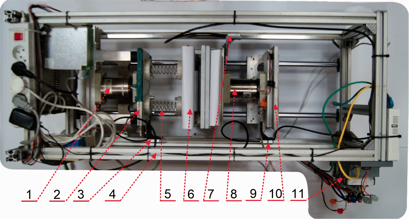
View of the laboratory stand used for testing the vibration reduction system.
The simulations were carried out with the assumption that disturbance displacement z(t) is realised by displacement of platform 2. The displacements x1(t), x2(t) of the vibroisolated subsystem and the damper mass mt are represented by displacements of platform 6 and platform 10. The measuring system was designed to implement the modified algorithm shown in the diagram (Figure 13) as green blocks. A controller with the FPGA allowed for obtaining the sampling frequency of 1 kHz.
Parameters of the disturbance signal were assumed to be the same as in the simulation calculations so that the quantitative comparison of results was possible. In the first part of the test, the disturbance signal z(t) was a sinusoidal of amplitude 1 mm and frequency 2 Hz, while in the second part, the amplitude was equal to 2 mm at the same frequency. The reduction system was configured before the test. The results of the measurements are presented in Figure 16. The upper figure shows the displacement of the vibroisolated plane and the assumed disturbance signal. The lower figure shows the power of the source placed in the motor circuit. The power of the source is a product of the source voltage and the current flowing in the linear motor supply circuit.
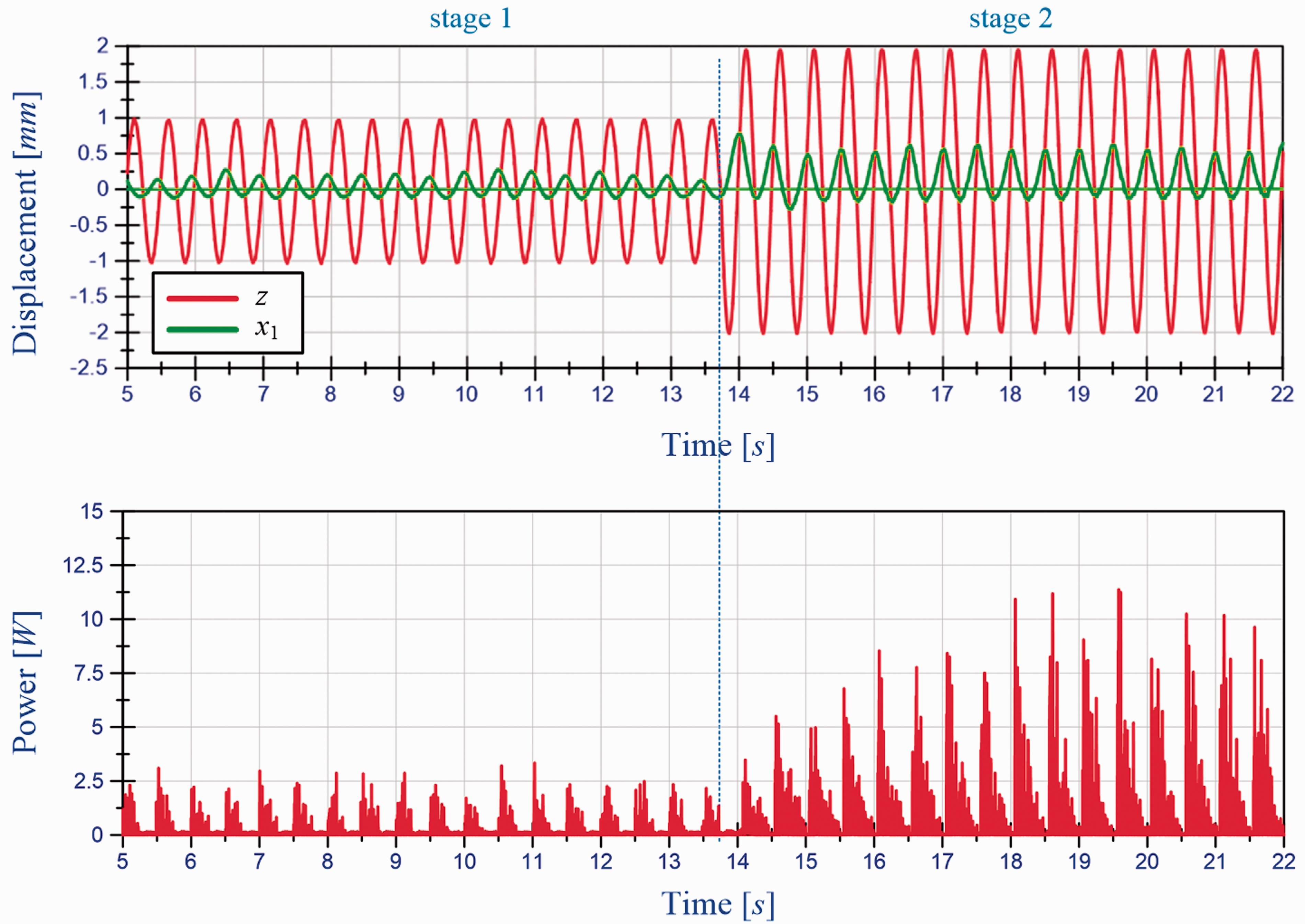
Time history of displacement of selected platforms and power.
Analysing the obtained results of measurement, it was noted that at fixed amplitude of the disturbance signal, the vibration reduction system operates with the smallest possible gain factor
Comparison of the average power graphs drawn on the basis of calculations and laboratory measurements indicates similarity of theoretical and experimental results. The graphs are not identical and the differences occur primarily in the time interval immediately following the change in the amplitude of kinematic excitation. After the disappearance of the transient components, the power values are similar. The differences are related to the fact that a number of properties of laboratory control system are not included in the calculations. Real subsystems used in laboratory have their own dynamics and they introduce among others additional delays and hysteresis in the whole system. As a result, the reduction of vibrations is less effective and additional phase shifts appear between the signals. Of course, the calculations can be extended with models covering disadvantageous phenomena – then the differences in results will be smaller. This was not done, to be able to assess the impact of different types of practical subsystems on the effectiveness of the vibration reduction system.
Summary
The proposed AVRD with a dynamic damper tuned with a sliding mode control algorithm is theoretically very effective. In a relatively short time after activation of this system, the vibroisolated subsystem reaches the position close to its equilibrium. There are, however, some difficulties with the practical implementation of the algorithm. The difficulties can be reduced by the optimum choice of the parameters of the sliding mode control algorithm depending on the current level of disturbances.
The paper includes an analysis of the influence of the choice of control parameters on transmission coefficients which are a measure of the vibration reduction effectiveness. The influence of the parameters on the electric power of the controlled voltage source supplying the electrodynamic linear motor was also analysed. The optimum parameters were determined. As a result of the analysis of the influence of the control parameters on the efficiency of the vibration reduction system, an algorithm of adaptive selection of the gain factor was proposed.
The operation of the vibration reduction system using the algorithms considered in the work was tested on a specially built laboratory stand. The results of the measurements confirmed the correctness of the computational analyses presented in the paper.
The proposed vibration reduction system ensures the low vibration level of the vibroisolated system in the broad frequency range, including resonance frequencies. Taking into account low energy consumption, the system can be classified as an effective and economical vibration reduction system.
The equilibrium position of the vibroisolated subsystem should be stable. In the literature on slide mode control stability,22,23 we can find a number of mathematical tools for analysing the stability of practical implementations of systems based on sliding mode control, but the proposed formulas (associated mainly with the creation of Lyapunov’s functions) use a number of coefficients and signal values limitation difficult to assess in practice. The authors considered the problem of stability in a less formal and not quite exact way from the mathematical point of view. 24 The concept assumes that the system reaches the sliding surface in finite time and then, in ideal case, the equivalent control keeping the system on the sliding surface. Taking into account the equation of the sliding surface, the equilibrium position of the platform is asymptotically stable in this case. Practical control law ‘is kept close’ to equivalent control but it introduces a number of negative phenomena from the stability point of view. For this reason, in practical realisation, the equilibrium position of the platform will not be asymptotically stable, but it remains stable. The presented intuitive approach to stability is confirmed by the measurement results.
Footnotes
Declaration of conflicting interests
The author(s) declared no potential conflicts of interest with respect to the research, authorship, and/or publication of this article.
Funding
The author(s) disclosed receipt of the following financial support for the research, authorship, and/or publication of this article: Research work 16.16.130.942.