
Abstract
This study aims to optimize the acoustic performance of a silencer with baffles having extension tubes. It considers the position, the number and the extension geometry of the baffles as design variables and sound transmission loss as the response variable to be optimized. The finite element analysis software ABAQUS is used to compute the response values for different combinations of design variables. The statistical design of the experiments provides a mathematical framework for such computer design optimization studies with multiple design variables. Yet, it has not been used for design optimization of silencers in the literature. In this study, simplex centroid mixture designs, a type of response surface method, are used in the statistical design of experiments. They can provide faster convergence on the optimization problem. The design involves one, two and three baffles with different positions and extension tube lengths. The outcome of this study indicates that obtaining ABAQUS software solutions at design points for each baffle number allows constructing nonlinear regression equations expressing the response variable as a function of the design variables. The equations obtained are then used to compute optimal values. Further evaluation of these equations indicates that better sound transmission loss values are obtained when the baffle number is increased, and the lengths of the extension tubes are set at high values. Moreover, it is possible to use the statistical experimental design approach implemented in this study for other types of silencers with different baffle geometries and design variables.
Introduction
Studies on sound reduction always attract the attention of researchers due to the negative effects of sound and noise on human health. Silencers are equipment used to reduce the volume of sound and noise. They reduce the sound pressure generated by sound-generating sources such as motors, fans, weapons by using intertwined perforated pipes, expansion chambers or various sound insulation materials. 1
Silencers are generally classified as reactive, dissipative and hybrid type according to designs and requirements. Reactive silencers generate dissipative sound waves caused by geometric discontinuity by means of acoustic impedance difference. Dissipative silencers transform sound energy to heat energy and thus decrease acoustic pressure fluctuations. Hybrid silencers are composed of reactive and dissipative silencers. The selection of the silencer type and the internal design depends on the frequency band of the sound and conditions of use. Reactive type silencers are commonly used as exhaust mufflers. This study proposes a new statistical experimental design approach for reactive silencers.
Early studies on silencer design began in 1950s. The attenuation characteristics of several acoustical elements were studied theoretically and experimentally by Igarashi and Toyama, 2 and four-pole matrices for evaluating muffler acoustics were developed by Miwa and Igarashi. 3 Also, the transfer matrix method (TMM) was improved to demonstrate the insertion loss prediction of acoustical elements by Sreenath and Munjal. 4 Most of the developments in the silencer theory have occurred after the application of the TMM,5,6 which was based on the calculation of the sound transmission loss (STL) curve with the help of the transfer matrices. These transfer matrices are based on one-dimensional linear wave propagation of the silencer elements. 7
In the past 20 years, researchers studied the acoustic performance of expansion-chamber type reactive silencers using analytical, numerical and experimental techniques. Ovidiu 8 investigated the acoustic performance of a reactive silencer with three expansion chambers using numerical and experimental techniques. Ji 9 developed a numerical approach to predict and analyze the acoustic attenuation performance of multi-chamber reactive silencers with inter-connecting tubes using a numerical approach. The effects of internal geometry on acoustic attenuation performance of the silencers were also investigated for optimal design. Selamet et al. 10 investigated the acoustic behavior of a circular dual-chamber muffler by using analytical, numerical and experimental methods. Their investigation included the effects of the presence of a rigid baffle in the chamber, the inner radius of the baffle, the position of the baffle, the extended inlet/outlet and baffle ducts. Selamet and Ji 11 developed a three-dimensional analytical approach to determine the transmission loss of circular expansion chambers with single-inlet and double-outlet mufflers and compared analytical results with boundary element predictions. Zhang et al. 12 used simulation for the analysis of acoustic attenuation performance of an expansion chamber silencer using boundary element method (BEM)-finite element method (FEM) coupled model for different shape, length and diameter. Pujari et al. 13 studied acoustical and engine performance of silencers which was predicted using FEM/BEM and computational fluid dynamics (CFD) techniques; the results were validated by experimental studies. Wu et al. 14 proposed a numerical method for the acoustic performance prediction on single-inlet/double-outlet and double-inlet/single-outlet expansion-chamber mufflers with rectangular sections. Wu et al. 15 proposed a formulation for the acoustic performance prediction on a single-inlet and double-outlet cylindrical expansion-chamber muffler by using the modal meshing approach and the plane wave theory. They were numerically analyzed on mufflers for various cases of length–diameter ratio and were compared with the FEM results.
Recently, many studies focused on the design optimization of silencers based on particular silencer configurations using advanced numerical techniques. Design constraints such a volume limitations and tight equipment layout make the selection of an appropriate acoustical mechanism increasingly more important. Bernhard 16 introduced the shape optimization of simple expansion mufflers by using design sensitivity matrices. Yeh et al. 17 used a shape optimization method for the optimal design of single chamber muffler with inlet/outlet pipe under space constraints. The STL values were obtained for different inlet–outlet pipe diameters, distances between input and output pipes and chamber diameters. STL was calculated theoretically and the results were numerically verified. Three different search algorithms, namely exterior penalty function method, interior penalty function method and feasible direction method, are used in the optimization. Yeh et al. 18 also proposed an optimization approach for the design of a single expansion muffler with an extension tube by changing the extension pipe diameter and lengths at the inlet and outlet. STL was calculated theoretically and using different numerical methods and then the accuracy of the solution is verified. In a similar study, Chang et al. 19 used the genetic algorithm (GA) for the design optimization of a double-chamber muffler by varying pipe diameters and lengths at the inlet and outlet. Another study using the GA was conducted by Yeh et al. 20 for the shape optimization of a double-chamber muffler with an extended tube: a single-chamber muffler with extended tubes is simulated and compared with Wang and Hsieh’s experimental data for the purpose of accuracy check in the mathematical model. The length of the inlet, outlet and middle pipes and the diameter of the middle extension pipe were changed. The STL values were found numerically. Chiu et al. 21 investigated the shape optimization of the single-chamber mufflers considering the flowing affect, combining the gradient methods and the GA under constrained space. They changed the muffler inlet–outlet pipe diameter, distance between the input and output pipes and the muffler chamber diameter. Chiu 22 also studied the shape optimization of multi-chamber plug-inlet mufflers neglecting the maximal back pressure using the GA. The effect of perforated pipe length and extension pipe length on STL was investigated. STL was found numerically for six different back pressure values. He optimized the multi-expansion chamber muffler shape with plug-inlet tube using the GA.
In some other work, Chang et al. 23 presented the shape design of a muffler with extended tubes optimized by the GA. Chang and Chiu 24 worked on the process of optimization single-chamber mufflers using neural network and GA under space constraints. Barbieri and Barbieri 25 described a new optimization methodology for the shape design of a single expansion muffler, which combined the FEA and Zoutendijk’s feasible directions method for mufflers’ shape design. Lima et al. 26 studied the application of shape and parametric optimization techniques in the study of reactive silencers with extended inlet and outlet ducts. Yu et al. 27 presented a systematic approach based on the sub-structuring modeling principle, considering the effects of various internal arrangements to investigate the effects of several typical silencer configurations and provide for possible system optimization. Yu et al. 28 also investigated sub-chamber optimization for three typical sub-chamber configurations using the patch transfer function approach.
In a recent study, 29 different types of silencers were designed, and the effects of the positions, type and the number of the baffles for each silencer was investigated on acoustic performance using theoretical, numerical and experimental methods. Silencers with extension baffle were observed to provide better performance compared to other types of silencers. Motivated by these results in Seçgin, 29 this study tries further to optimize the performance of silencers with extension tubes in order to get the best acoustic results. To this end, first, an assessment of the STL-frequency graphs and STL-root mean square (RMS) values obtained from the FEA is presented for silencers with extension tubes. Then, an optimization study is performed with respect to the number and location of the baffles using STL-RMS values from the FEA in a response surface optimization framework. A mixture design, a type of response surface method used in statistical design of experiments, is employed for this purpose.
The aforementioned search algorithms and GAs used for design optimization of silencers aim at finding an optimum with a minimal number of search points; they may stop at a local optimum before reaching the global optimum. Response surface methodology, on the other hand, aims at modeling the mathematical relationship between input and output parameters (which is simply called the response surface), and hence finding an optimum with a minimal, predetermined number of design points. The response surface also provides insights about global optimality of candidate solution. In this study, the optimization of both the number and position of the baffle in the silencer was carried out by using a minimum number of STL-RMS data with the Simplex Centroid Mixture Design method. Also, using this method, the optimal point can be predicted globally by analyzing the response surface. To our best knowledge, this is the first academic study demonstrating how this methodology can be used for the design of silencers.
Material and method
Acoustical performance of a silencer is measured by one of the insertion loss (IL), TL and noise reduction (NR) parameters. 5 IL is the difference between the acoustic powers radiated with and without the silencer. TL is the difference between the power incident on the silencer and that transmitted downstream into an anechoic termination. NR is the difference in sound pressure levels at two arbitrarily selected points in the inlet and outlet of the silencer. Among these acoustic parameters, TL is the only one that can be easily calculated and measured in this study. ILs and TLs are both used when describing sound reducing measures, although TL is more common and is related more to the sound power which is generally better to use. Both methods are independent of the flow.
The methods used for calculating STL values using both the FEM and BEM are the traditional laboratory methods, the four-pole transfer matrix and the three-point methods. For this study, the STL analyses were carried out based on some assumptions regarding the boundary conditions: The three-point method is used to calculate the STL value of the silencers. 30
Silencer model
Dimensions of existing commercial products were used for the modeling study of the silencer. They were designed with two and three dimensions. Solid models of the baffles and the silencers have been created by the CATIA V5 computer-aided design software, some examples of which are shown in Figures 1 and 2. Using these solid models, the inner acoustic media was modeled with two dimensions. The solid model of a baffle with an extension tube is given in Figure 1. The extension tube has an inlet and an outlet part.
A baffle with extension tubes.
Silencer model with one baffle (a); with two baffles (b); and with three baffles (c).
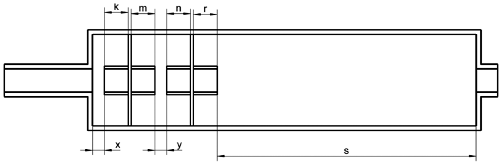
Figure 3 shows a silencer having three baffles with extension tubes. The variables k, m, n, r, t and v in Figure 3 represent the lengths of the inlet and outlet parts of the extension tubes, from left to right, respectively; also the variables x, y, z and s are the distances between consecutive extension tubes as shown in the figure. In a silencer with two baffles, z, t and v do not exist in Figure 3 (or equal to zero). When there is only one baffle, only x, k, m and s can be greater than zero as shown in Figure 4.
Schematic showing the position of variables for three baffles in a silencer model.
The dimensions of silencer model with one baffle extension tube.
The length and the diameter of the expansion chamber for all silencer models have been taken as 165 mm and 40 mm, respectively, as shown in Figure 4. The lengths of inlet and outlet tubes are 37 mm and 7 mm, respectively, and their diameters are 10 mm.
Finite element analysis
The FEA models were created by the ABAQUS software. The acoustic media are assumed to be steady in the FEA models. Plane wave assumption is appropriate when the diameter of the pipe forming the silencer is smaller than half of the sound wave. 31 Therefore, in acoustic analyses up to 3000 Hz, the pipe diameter should be smaller than 56 mm. Plane wave assumption was made because the models created in this study had pipe diameters smaller than 39 mm.
For determining the size of the mesh element, the rule of taking at least two rows of elements on the smallest surface is used. The smallest part of the silencer is the baffle, and its thickness and geometry are effective in determining the element size. Therefore, the element size was first taken as 1 mm, and the analysis model was created and run. Then, the element size was reduced to 0.5 mm and the solution was obtained. Changing the model geometry was an important consideration for determining the element size. In addition, the frequency range of the acoustic analysis was considered in determining the element size. The frequency (Hz)–STL (dB) graphs were obtained from the solution of the silencer FEA models with the element sizes of 0.5 mm and 1 mm. Since the two graphs are compatible with each other, the element size was chosen as 1 mm in order to reduce the solution time. 29
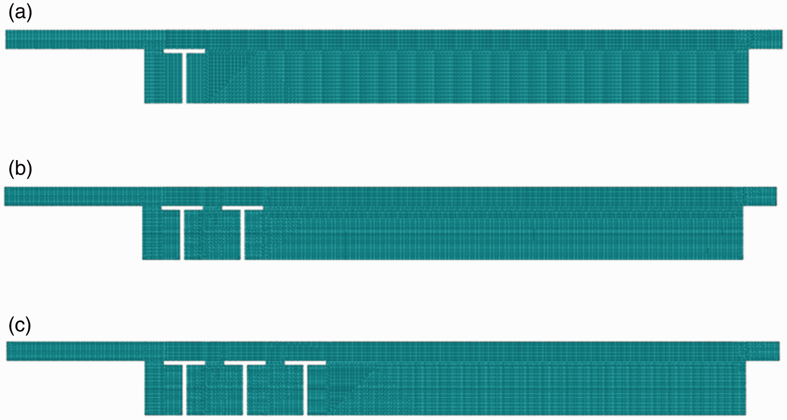
The selection of the element type is also important in the analysis. It is necessary to use triangular elements in some complex geometries. However, a complex geometry is not used in this study; the element size and the acoustic mesh type were 1 mm and ACAX4 four-node linear axisymmetric quadrilateral, respectively. The FEA model consists of 13,316 elements and 13,818 nodes. The material properties of the acoustic media are given in Table 1.
Material properties of acoustic field inside the silencers.
The finite element acoustic analysis model of the silencer was created in 3D and 2D, and the results were compared for the same mesh type and size. The frequency (Hz)–STL (dB) graphs of both models were identical (Figure 5). The two-dimensional and axial symmetrical formation of the finite element model shortens the solution time. In this study, 2D analysis models were used because of the large number of analyses required.

STL graphs of two and three dimensional silencer model for a silencer with no baffle, 2D;  3D.
3D.
Experiments were conducted using silencers without a baffle and with two-chamber silencers with an extension pipe for experimental verification. The simulation results and a comparison of numerical analysis and test results are also shown in Figures 6 and 7. As can be seen from the graph in Figures 6 and 7, the results are compatible with each other.

FEA and experimental STL results of a silencer without a baffle. FEA;  Experimental.
FEA and experimental STL results of a two-chamber silencer with an extension tube, FEA; Experimental.
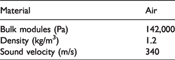
In the FEA evaluations, the outlet surface of the silencer was assumed to be non-reflective, and at the inlet nodes, acoustic pressure was defined as uniform with a magnitude of 1. The FEA is based on continuous audio input. The finite element models of a silencer consisting of one, two, and three extension tubes are shown in Figure 8(a) to (c).
The FEA models of the silencers with extension tubes. (a) With one baffle, (b) with two baffles and (c) with three baffles.
Results and discussion
Investigation of the silencer performance with and without extension tubes
In order to compare the performances of silencers with and without extension tubes (straight baffles), initial values are assigned to the parameters in Figure 3 based on past experience; the values are given in the first column of Table 2. The FEA results of silencers having one baffle with and without extension tubes are given in Figures 9 and 10, respectively.
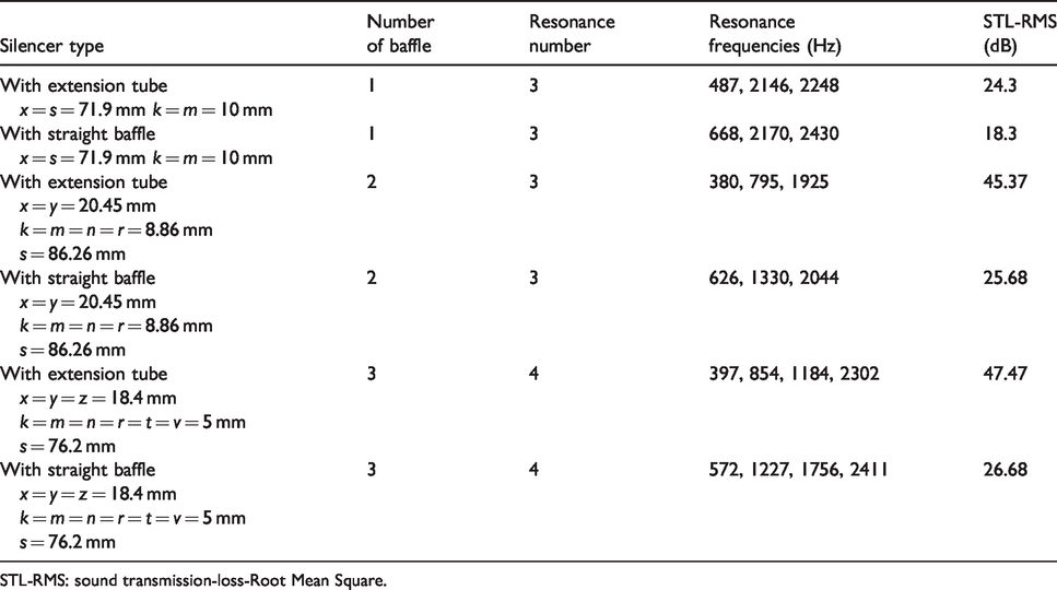
Comparison of the results obtained from the STL-frequency graphs of silencers.
STL-RMS: sound transmission-loss-Root Mean Square.
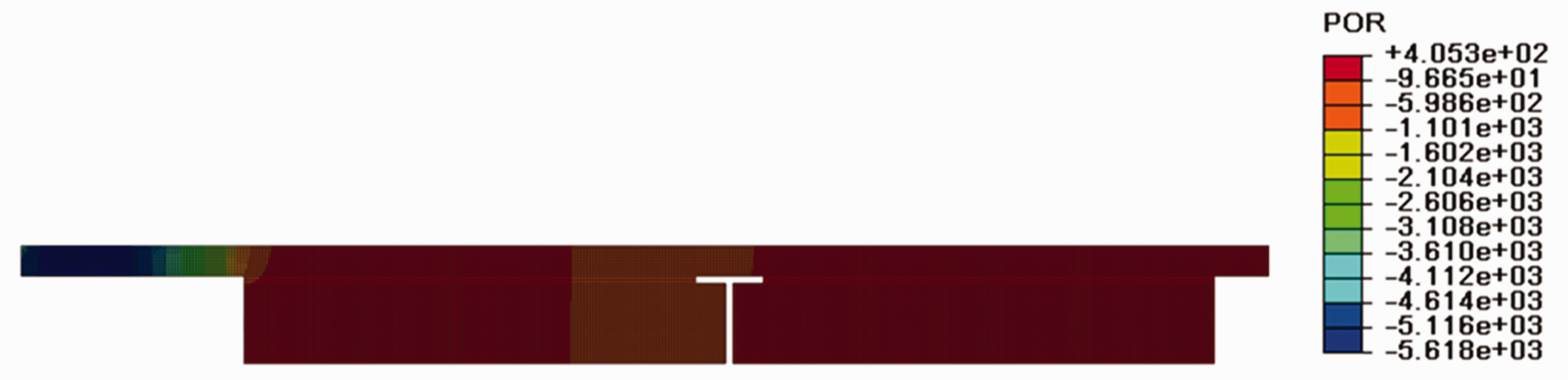
Sound pressure FEA result of the silencer with an extension tube.
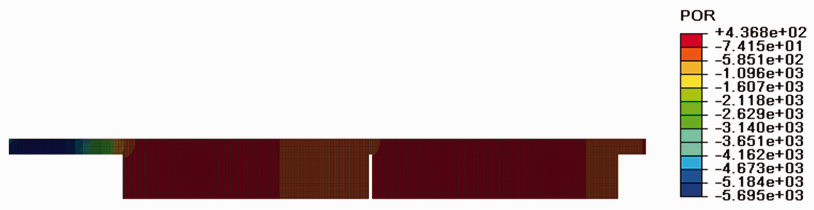
Sound pressure FEA result of the silencer with a straight baffle.
Also given in Figure 11 are the numerical results obtained from the FEA. It shows that the STL values for the silencer with an extension tube are higher for a range of 600 Hz–2000 Hz and for 2300 Hz and above 38 dB.
FEA STL results of the silencer. One baffle with extension tube, one straight baffle.
Similar results have been obtained from the FEA of silencers with two and three baffles. As shown in Figure 12, in a frequency band of 0–3000 Hz, the best STL performance has been obtained from the silencer having three baffles with extension tubes. The second best STL performance has been obtained from the one having two baffles with extension tubes. Details are provided in Table 2. Table 2 shows that the existence of an extension tube for all the investigated silencers has a positive effect on the STL-RMS performance. Also, as it can be observed in Table 2, the resonance numbers and resonance frequencies differ according to the number of baffles and existence of extension tubes.
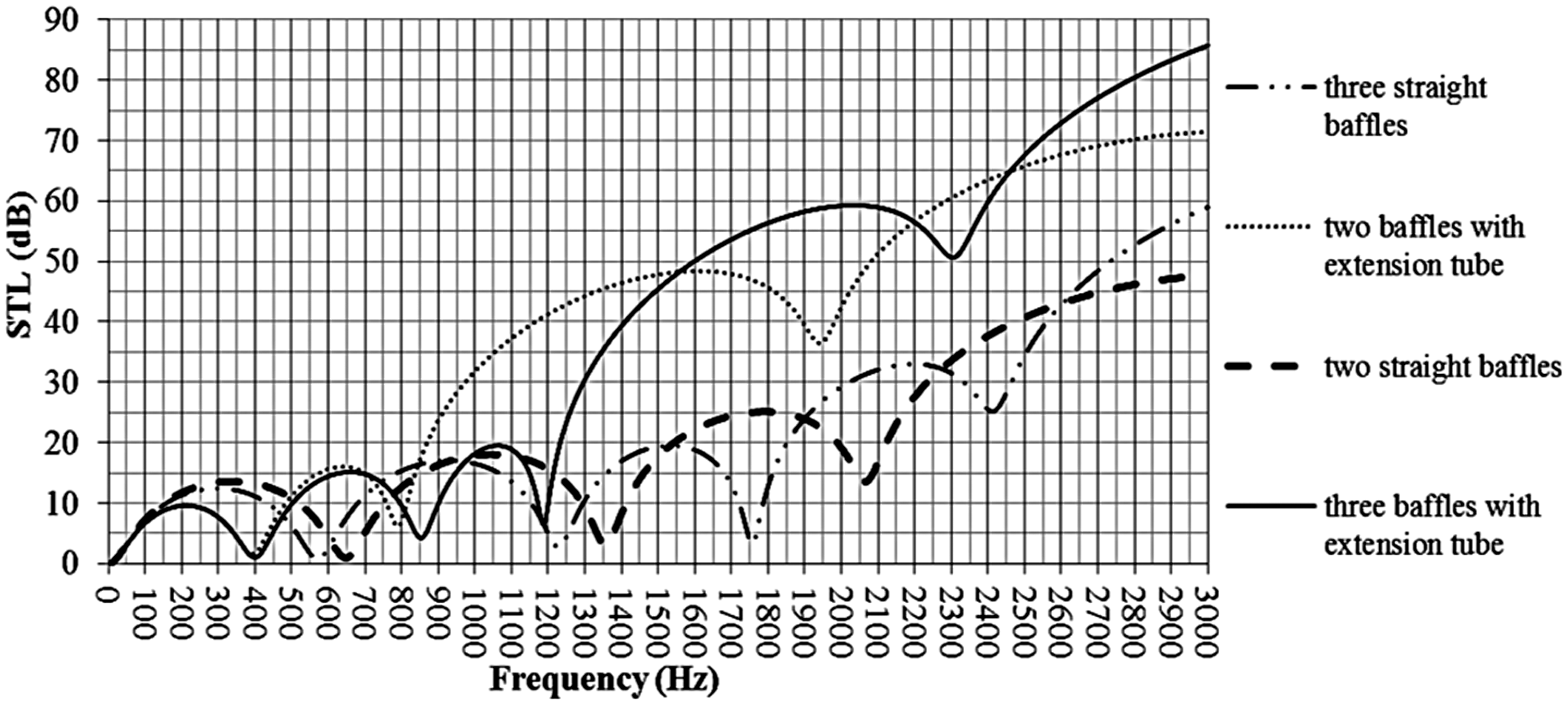
FEA STL results of silencers with two and three baffles.
From the STL-frequency graphs, the performances can be determined only at preferred frequencies of the silencers. However, in order to assess the general performance, STL-RMS values are chosen as a measure of comparison in the following section. It should be kept in mind that the comparisons in this section are only valid for the parameter values specified in Table 2. Therefore, when they are changed, it requires a new analysis to show whether the addition of extension tubes to straight baffles provides better performance or not. While it is quite challenging to prove that the addition of extension tubes is always better, the following section shows that increasing the length of the extension tubes results in higher STL-RMS values according to the fitted response surface equations.
Design optimization
The results of the previous sections are encouraging enough in favor of using extension tubes that an optimization of silencers with extension tubes is worth further examining. In the optimization study, total length and radius of the silencer are kept fixed, and the effects of number of baffles, relative positions of the baffles and the length of the extension tubes are examined. The fact that the total length is fixed makes the mixture designs the most suitable design tool among statistical experimental design methods.
Response surface methodology is a mature field of statistics investigating and modeling the relationships between several design parameters and one or more response variables usually in the form of polynomial functions. The polynomial models are used to optimize the response variables. Some advantages of using a response surface method are as follows: the combinations of design parameters that the experiments will be run at are determined before actually running the experiments; a minimum number of experiments are used, and the statistical framework for analyzing results of the experiments and modeling the relationship is well established. The polynomial models allow finding optimal design parameter values that are different from the ones used in the experimentations.
Simplex centroid mixture designs were chosen in this study, as the response surface method and the designs and analyses were carried out using Minitab® statistical software. Mixture designs allow using very high and low combinations of design parameters, for instance, using combinations of low x and high s, and high x and low s in Figure 4. Therefore, a better coverage of the design space, the multidimensional space that includes all possible parameter value combinations, is achieved. In contrast, other design methods such as factorial designs and central composite designs provide poorer coverage. A good coverage enables better modeling the response surface, i.e. the relationship between design parameters and the response variable, hence, increases the likelihood of estimating the true optimal.
In the following sections, three independent analyses are performed for silencers with one baffle, two baffles and three baffles. As the number of baffles increases, so does the number of parameters; this increases the number of simulation experiments in an exponential fashion. Therefore, more than three baffles are not included in this study. Even this limitation was not enough to obtain a realistic number of simulation experiment runs, since each run takes about 15 min on a 4 CPU and 8 GB Memory workstation computer. As a further constraint, the baffle is positioned at the middle of the extension tubes, hence k = m in Figure 13, for instance.
The model of the silencers with one baffle.
Analysis with one baffle
As shown in Figure 13, there are four parameters, x, k, m and s whose sum is hold fixed; k = m and the sum of k + m is denoted by w32,33


Simplex centroid design for this case is given in Table 3 with STL-RMS values. The minimum parameter values are specified as 5 mm (prescribed minimum distance). Note that the values of k and m are the same; the design is based on three parameters, x, w and s.
Simplex centroid design for one baffle.
STL-RMS: sound transmission loss-root mean square.
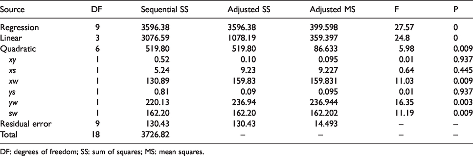
A quadratic mixture model is used for regression analysis. The associated ANOVA table is given in Table 4. At a significance level of α = 0.10, the linear and quadratic term are significant. The fitted regression equation is

ANOVA table for one baffle.
DF: degrees of freedom; SS: sum of squares; MS: mean squares.
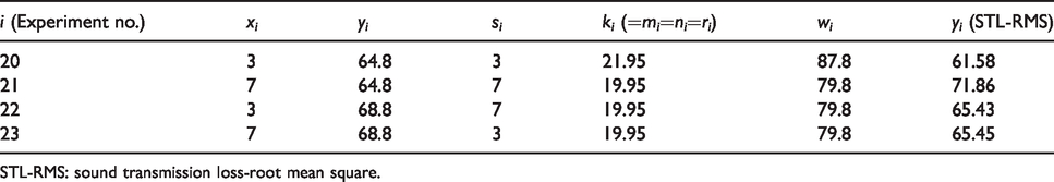
Factorial design around the current optimum for one baffle.
STL-RMS: sound transmission loss-root mean square.
The experiment i = 14 in Table 5 gives the optimum result with x = 7 mm and s = 7 mm. Considering the experiment i = 3 together with the results in Table 5 suggests that when x and s are set at 5 and/or 7 mm, near-optimal results are obtained. On the other hand, experiment i = 7 indicates another alternative with higher x and s, where x and s are equal. Keeping x and s equal at 20, 30, 40 and 50 mm, equation (3) produces STL-RMS values 43.93, 43.82, 42.37 and 39.57, respectively.
Analysis with two baffles
In this case, there are seven parameters, x, k, m, y, n, r and s shown in Figure 14, whose sum is hold fixed; k = m = n = r (the two baffles are kept identical).


The model of the silencers with two baffles.
Simplex centroid design for this case is given in Table 6 with STL-RMS values. The minimum parameter values are specified as 5 mm. Note that the values of k, m, n and r are the same; the design is based on four parameters, x, y, s and w.
Simplex centroid design for two baffles.
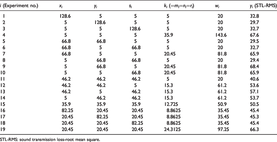
STL-RMS: sound transmission loss-root mean square.
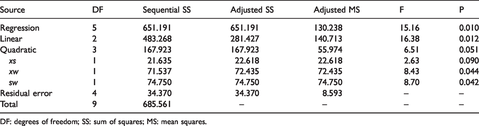
As in the one baffle case, a quadratic mixture model is used for regression analysis. The associated ANOVA table is given in Table 7. At a significance level of α = 0.10, all the linear terms and the quadratic term xw, yw and sw are significant. The fitted regression equation is

ANOVA table for two baffles.
DF: degrees of freedom; SS: sum of squares; MS: mean squares.
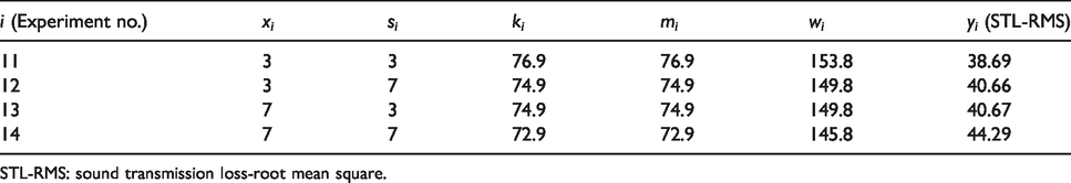
Factorial design around the current optimum for two baffles.
STL-RMS: sound transmission loss-root mean square.
Analysis with three baffles
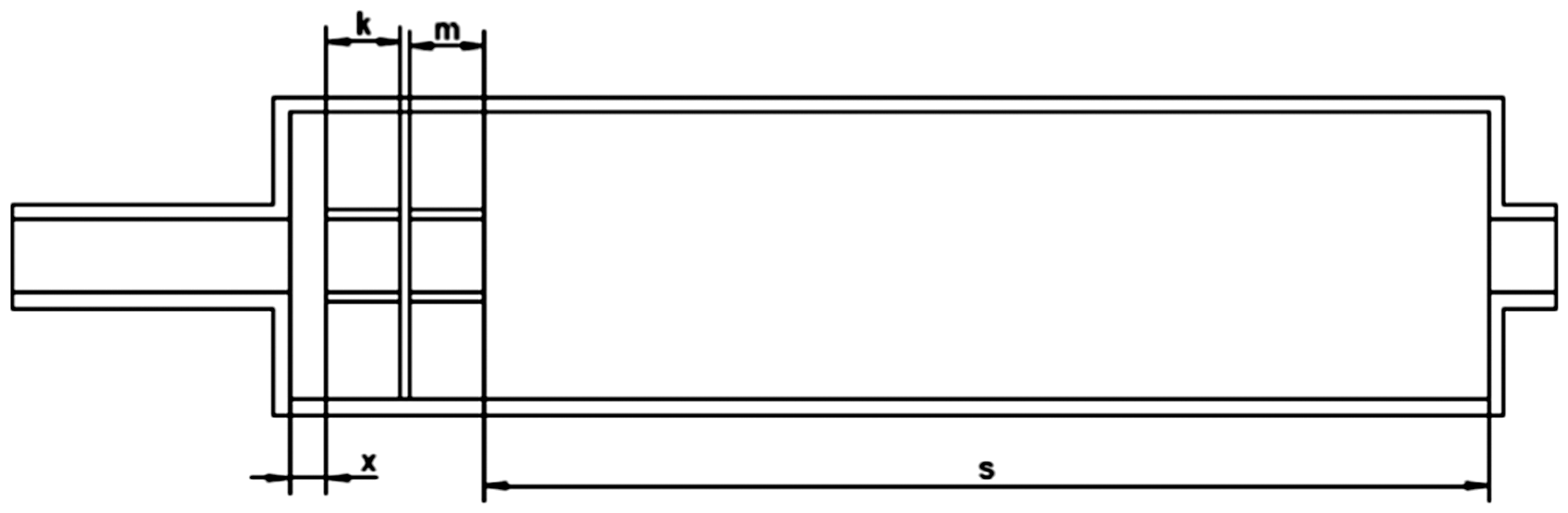
In this case, there are 10 parameters, x, k, m, y, n, r, z, t, v and s as shown in Figure 15, whose sum is hold fixed; k = m = n = r = t = v (the three baffles are kept identical).


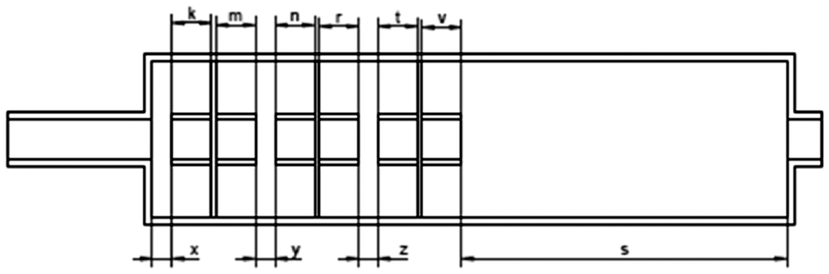
The model of the silencers with three baffles.
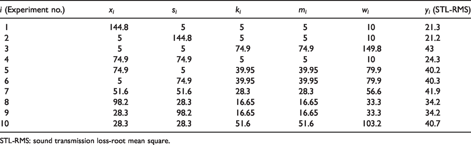
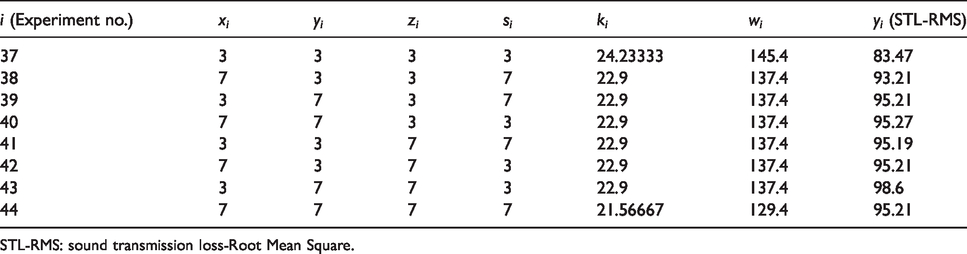
Simplex centroid design for this case is given in Table 9 with STL-RMS values. The minimum parameter values are specified as 5 mm. Note that the values of k, m, n, r, t and v are the same; the design is based on five parameters; x, y, z, s and w.
Simplex centroid design for three baffles.

STL-RMS: sound transmission loss-root mean square.
As in the previous cases, a quadratic mixture model is used for regression analysis. The associated ANOVA table is given in Table 10. At a significance level of α = 0.10, all the linear terms and the quadratic term xw, yw, zw and sw are significant. The fitted regression equation is

ANOVA table for three baffles.
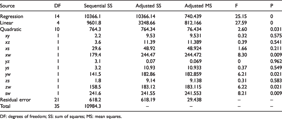
DF: degrees of freedom; SS: sum of squares; MS: mean squares.
Factorial design around the current optimum for three baffles.
STL-RMS: sound transmission loss-Root Mean Square.
Conclusions
In this study, simplex centroid mixture designs were employed for design optimization of multi-chamber reactive type silencers. It considered one, two and three baffles with changing positions and extension tube lengths. The ABAQUS software was used to compute the response values for different combinations of design variable values. The optimal or near-optimal performances are obtained when the distances between the baffles are set at their minimums, 5 mm was taken in this study; hence, the length of the extension tubes was at their maximums. Also, as the number of baffles increases, better results are obtained; the optimal STL-RMS values are 44.29, 71.86 and 99.85 for one, two and three baffles, respectively. Therefore, better values should be expected when the baffle number is increased and the distances between the baffles are kept at their minimums.
Fitted response surface equations (3), (6) and (9) also indicate that increasing lengths of the extension tubes results in higher STL-RMS values, as the equations are increasing functions of the parameter k. While the design space did not include straight baffles (k = 0), assuming that the equations are still valid for k < 5 mm, it can also be concluded that silencers with extension tubes provide higher STL-RMS values than those without extension tubes for up to three baffles.
It was observed that using quadratic mixture models suffices because of the high R2 values, higher order models are not needed. Quadratic models showed that interactions between the baffle length and distances between baffles are all statistically significant (i.e. xw, yw, zw, sw terms in Table 10), but interactions between the distances are not (i.e. xy, xz, yz, etc. in Table 10).
This study showed that simplex centroid mixture designs are suitable tools for design optimization of silencers. They are preferred to other design-of-experiment methods, since they provide a better coverage of the design space, thereby increasing the probability of finding better near-optimal solutions. As the number of baffles increases from one to three, the number of design points increases from 10 to 36. Due to the high computation time, this study limited the number of baffles to three. On the other hand, when there is no extension tube, designs with more baffles can be studied, as the number of parameters will be reduced.
As a final remark, the design-of-experiment methods can also be compared with their alternatives, in a general scheme. A well-known alternative method employed in many engineering designs is changing one-variable at a time while keeping the others fixed; this is shown to be inferior to design of experiment methods, since they lack nonlinear modeling capability. Another method, which was used in silencer design, is GA. It is known to be very efficient in finding optimal solutions; however, it fails to provide an explicit formula relating design variables with the response. Also, it cannot test whether the design variables have a statistically significant impact on the response.
Footnotes
Declaration of conflicting interests
The author(s) declared no potential conflicts of interest with respect to the research, authorship, and/or publication of this article.
Funding
The author(s) received no financial support for the research, authorship, and/or publication of this article.