
Abstract
In this study, the nonlinear dynamic analysis of the hybrid squeeze film damper mounted on a gear-rotor-bearing system is presented. The strong nonlinear oil film force, nonlinear rub-impact force between the rotor and stator, and the gear meshing force are considered in this study. The bifurcation diagrams are plotted using a dimensionless imbalance factor, damping coefficient, and speed ratio as control parameters in this study. The beginning of chaotic motion is identified by phase diagrams, power spectrum, Poincaré maps, bifurcation diagrams, maximum Lyapunov exponent, and the fractal dimension of the system. The numerical results provide useful insights into the design and development of a gear-rotor-bearing system for rotating machinery that operates at high speeds and highly nonlinear conditions. Hybrid squeeze film damper is used to suppress irregular dynamic behaviors and reduce greater amplitude, even if the rotational speed of the rotating machine is higher, which is also confirmed in this study.
Introduction
Gears play an important role in the transmission system, especially for rotor bearing systems and turbomachinery, therefore, the consideration of gears transmission in rotor-bearing systems is needed. The rub-impact effect is a common and important phenomenon that occurs between the rotor and the stator. These effects may cause the rotating system to become instable. The dynamic analysis of the gear-rotor-bearing system with rub-impact effect is therefore important for analyzing rotating machinery. In order to control the dynamic stability of the gear-rotor-bearing system with the shock effect, we take the hybrid squeeze film damper (HSFD) to control this kind of system. The HSFD is actually a useful tool, and has been well developed and used in many fields. A squeeze-film damper bearing is actually a special type of journal bearing with its journal mechanically prevented from rotating, but it is free to vibrate within the clearance space. The squeezing action produces hydrodynamic forces in the fluid film. A squeeze-film damper bearing can be designed such that the journal can statically find its own position within the clearance, or be held centrally within the clearance, by retaining the springs. If the retaining springs are not used, the influence of contact and wear at zero speed will occur and it will add to the complexity of analysis of the squeeze-film damper bearing. In a squeeze-film damper bearing-rotor system, the fluid support pressure is generated entirely by the motion of the journal and depends on the viscosity of the lubricating fluid. However, the hydrodynamic pressure around the bearing is nonlinear, as it may cause fairly large vibrations of the rotor complicating the analysis of this system.
Some literatures have been studying on the subjects about squeeze-film dampers, and have also found many interesting and outstanding results. Morgan and Cameron 1 were the first researchers to focus on the analysis of porous metal bearings under hydrodynamic conditions. Many theoretical and experimental studies have performed on the analysis of the performance. Savoulides and Breuer 2 analyzed the low-order model of a very short hybrid gas bearing. The analysis shows that the best way to run bearings in a hybrid model is by using the bearing-dependent low-speed hydrostatics and high-speed hydrodynamics. Adiletta 3 proposed a study of dynamics of an unbalanced rigid rotor suppored by squeeze film dampers with two-lobe wave bearings. Simulation results showed that two-lobe wave geometry influences the lubricating behaviors of the system and improves some unstable branches and the whirling phenomenon. Faris et al. 4 showed their observation of a rotor-bearing system containing composite and non-composite squeeze film dampers. They found that the performance of squeeze film damper improved with increasing oil pressure and length/diameter ratio within the range tested. Zhang et al. 5 presented the cell mapping method and experimental observations of multiple-objective design optimization of squirrel cage for squeeze film damper. Both the theoretical results and experimental results proved that the multi-objective optimization method offers a novel and promising tool for squirrel cage design in real industries. Hsu et al. 6 discussed the nonlinear dynamic with effects of flywheel eccentricity in a turbine generator with a squeeze film damper. The effect of flywheel eccentricity was proved to be an important factor. Arghir et al. 7 performed experiments on a flexure pivot tilting pad hybrid gas bearings for load-on-pad (LOP) and load-between-pad (LBP) configuration under various imbalanced conditions. San Andrés and Ryu 8 experimented with a curved pivot tilt pad hybrid gas bearing to perform a pad loading and pad load configuration under various unbalanced conditions. San Andrés and Ryu 9 introduced a strategy to employ an inexpensive air pressure regulator to control the supply pressure into the hybrid bearings, and both the theoretical results and experimental results showed that it reduced or even eliminated high amplitudes of rotor motion while crossing the system’s critical speeds. El-Shafei 10 proposed a concept of actively controlling high speed rotating machinery through an experimental and analytical method. The control mechanism composed by a HSFD and found the usage of a HSFD will be able to reduce the amplitude of vibration of the rotating machinery. Li and Chen 11 showed that a HSFD with piezoelectric crystal electrohydraulic active control not only overcomes the bi-stable problem, but also restrains the shock in the rotor supporting system. Chen et al. 12 performed a theoretical analysis of a hybrid squeeze-film damper-mounted rigid rotor with active control and found an abundant amount of HSFD can suppress nonlinear dynamic responses. Amina et al. 13 applied finite difference method to simulate the performance of three- and four-lobe hybrid journal bearings. They proved that the usage of a hydrostatic squeeze film damper loaded between pads is significantly influenced by the flow regimes, and the numerical results presented in this work can be useful to the bearing designers. Recently, Chang-Jian14–16 presented gear dynamic analysis mounted with HSFD combined with turbulent flow effect and rub-impact effect in the bearings, and proved that HSFD can be used to suppress those irregular or undesired vibrations occurring in the rotating machines.
To avoid the undesirable non-synchronous vibrations, hybrid squeeze-film dampers (a combination of hydrostatic and hydrodynamic ranges) with active controls are designed and simulated in this study. Numerical examples are given for a gear-rotor-bearing system supported by HSFD with two pairs of hydraulic actuators with PD controllers. To help the gear-rotor-bearing system to avoid an undesirable non-synchronous vibration, a suitable increased proportional gain is also applied to this system. The reminder of this paper is organized as follows. The Mathematical modeling section derives dynamic models for the gear-rotor-bearing system with the nonlinear suspension effect, nonlinear rub-impact effect, strongly nonlinear gear mesh force, and strongly nonlinear oil-film force under the suspension of HSFD. The Numerical results and discussions section presents the numerical analysis results obtained for the behavior of the gear-rotor-bearing system under various operational conditions. Finally, the Conclusions section presents some brief conclusions.
Mathematical modeling
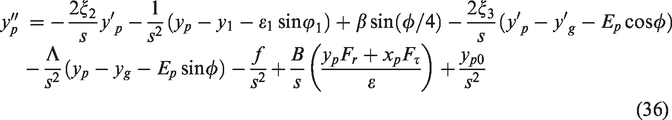
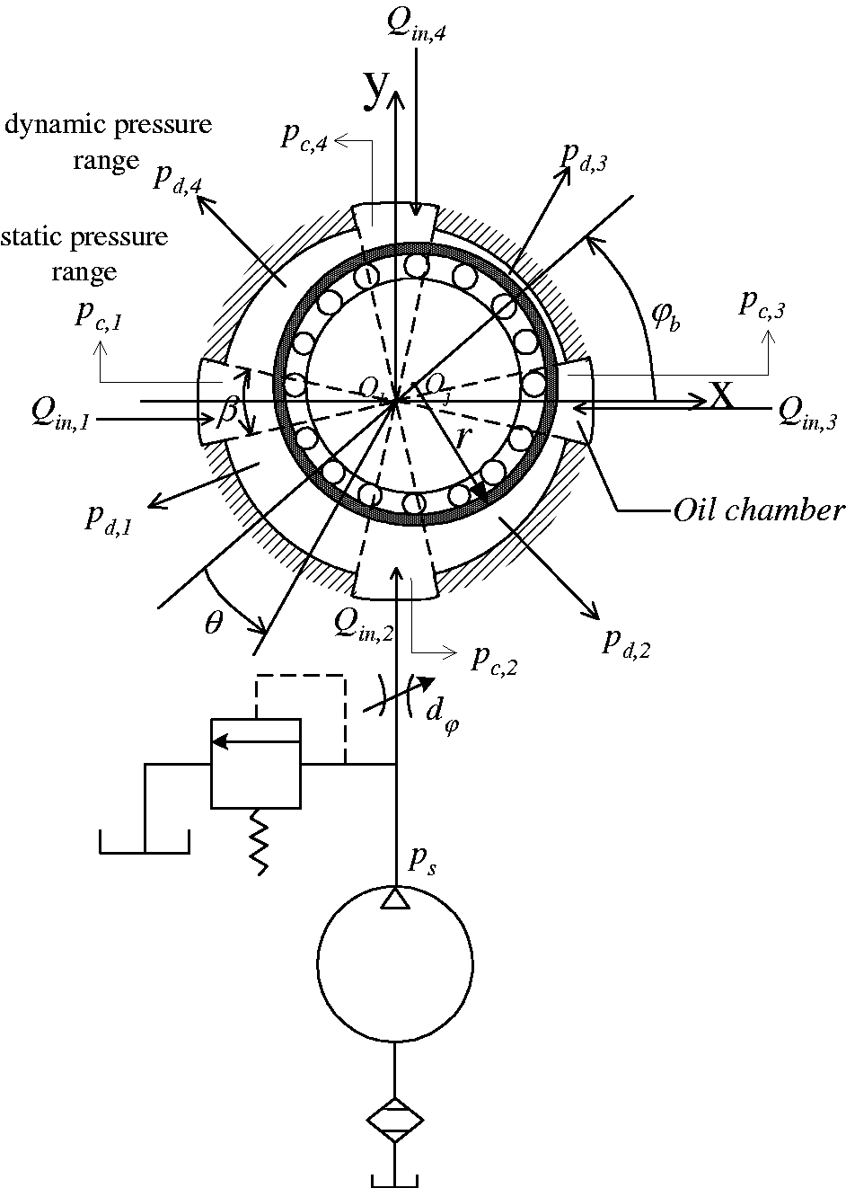
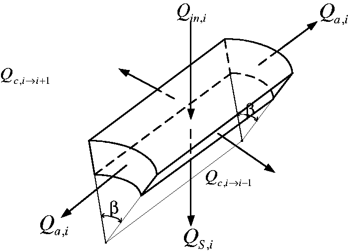
Figure 1 shows a gear-rotor-bearing system equipped with HSFD under the assumptions of nonlinear rub-impact force, nonlinear fluid film force, nonlinear suspension effect, and nonlinear gear meshing force. Nonlinear rub-impact force can be found between the rotor and the stator. The bearing consists of four hydrostatic chambers and four hydrodynamic regions. The structure of this type of bearings should be popularized to consist of 2 N (N = 2, 3, 4…) hydrostatic chambers, and 2 N hydrodynamic regions. In this study, the oil pressure distribution model in HSFD was proposed to integrate the pressure distribution in the dynamic and static pressure regions, as described in Section 2.1.
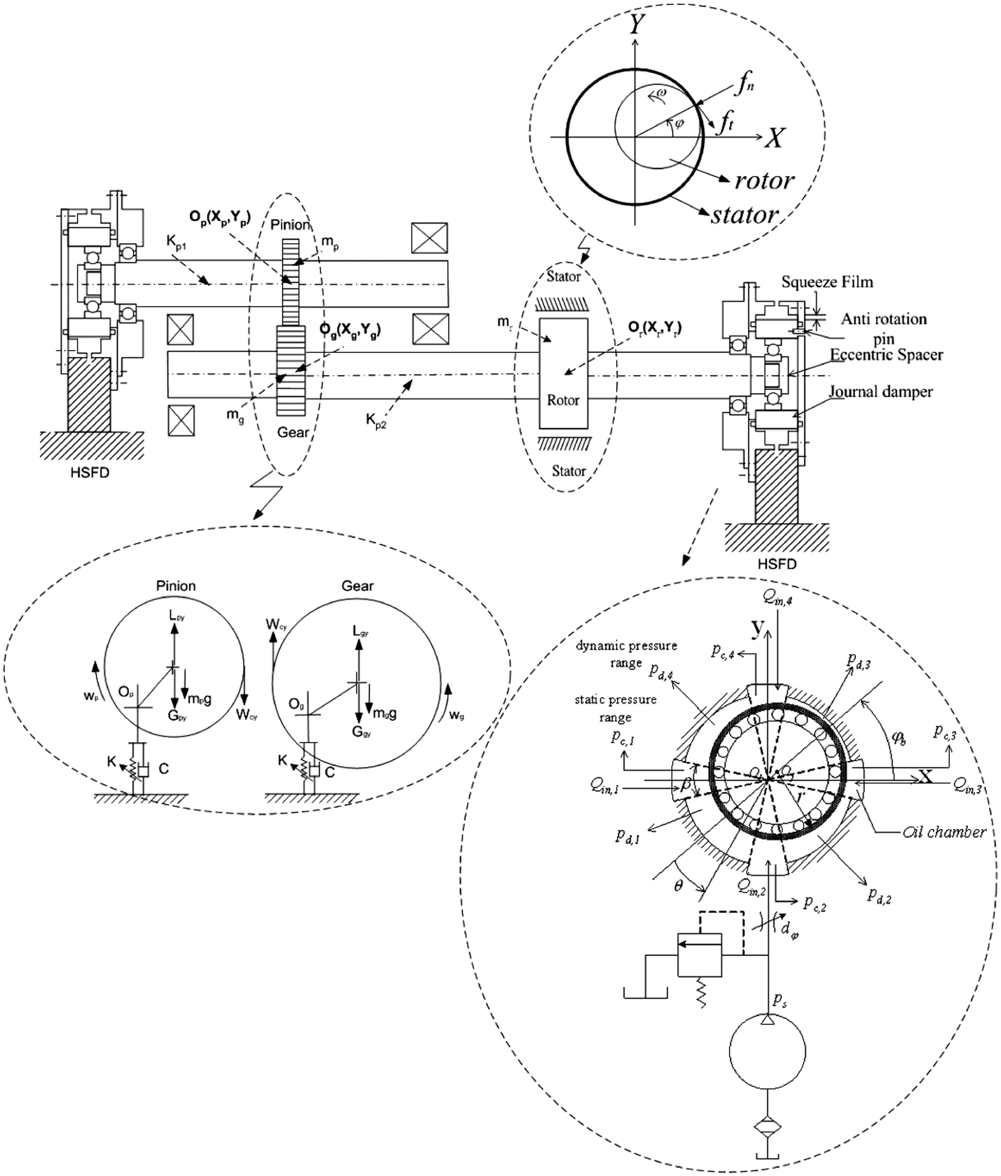
Schematic illustration of hybrid squeeze-film damper mounted on the gear-rotor-bearing system, cross section of HSFD and model of force diagram for pinion and gear.
The instant oil film supporting force for HSFD
In order to analyze the pressure distribution, the Reynolds equation of constant lubricant properties and incompressibility should be assumed, and then the Reynolds equation is as follows
The support area of the HSFD should be divided into three areas: static pressure zone, rotational direction dynamic pressure zone, and axial dynamic pressure zone, as shown in Figure 1. In the part of HSFD with
According to the aforementioned conditions, the instantaneous oil film pressure distribution is as follows.
The instant pressure in rotating direction within the range of
The instant pressure in the axis direction within the range of

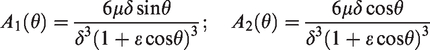
The instantaneous oil film force of the different elements is determined by integrating equations (2) and (4) onto the area of the journal sleeve. In the static pressure zone, the force is shown


In the dynamic pressure region in the direction of rotation, the force is shown
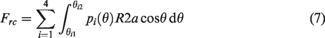
In the axial dynamic pressure region, the force is shown.


The damping forces generated in the radial and tangential directions are determined by summing the above supporting forces. It is shown below.


The gear meshing force


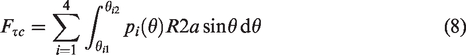
The rub-impact force
From Figure 1, the radial impact force


Then we could acquire the rub-impact forces in the horizontal and vertical directions.


Dynamics equation
Applying the principle of force balance, the force acting on the center of journal 1, i.e. Oj1 (Xj1, Yj1), center of journal 2, i.e. Oj2 (Xj2, Yj2), equations of motion of Og(Xg, Yg) and Op(Xp, Yp) in Cartesian coordinate form and equations of motion of the center of bearing 1 (X1, Y1), the center of bearing 2 (X2, Y2) and the center of the rotor under the assumption of nonlinear suspension are given by


In which fe1 and fφ1 are the viscous damping forces in the radial and tangential directions for the center of journal 1, respectively, and fe2 and fφ2 are the viscous damping forces in the radial and tangential directions for the center of journal 2, respectively, and fe and fφ are the viscous damping forces in the radial and tangential directions, respectively.
The origin of the o-xyz-coordinate system is taken to be the bearing center O
b
. Dividing these two equations by
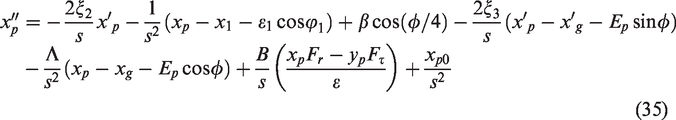


Equations (35) to (40) describe the nonlinear dynamic of the gear-rotor-bearing system. In the current study, the approximate solutions of these coupled nonlinear differential equations are obtained using a fourth-order Runge–Kutta numerical scheme. In order to control the gear-rotor-bearing system, four hydraulic actuators are designed to control the oil flow in each oil chamber to change the pressure of the four oil chambers (for i = 1, 2, 3, 4), as shown in Figure 2 and Figure 3. The kinetic equations in the four oil chambers are discussed and well presented in Chen et al. 12
The flow rate control structure of HSFD (only shows the 2nd oil chamber).
The change of flow rate in ith oil chamber.
Numerical results and discussions
Without hydraulic active control
In the simulations, the system parameters are assigned the following values:
The fourth-order Runge-Kutta method is used to solve the nonlinear dynamic equations in equations (35) to (40) of a gear-rotor-bearing system with strong nonlinear oil film force, nonlinear rub-impact force, and gear meshing force. The time step in the iterative solution procedure was assigned a value of π/300 and the termination criterion was specified as an error tolerance of less than 0.0001. The time series data corresponding to the first 800 revolutions of the two gears were deliberately excluded from the dynamic analysis to ensure that the analyzed data related to the steady-state conditions. The numerical results solved by the fourth-order Runge-Kutta method were used to generate the dynamic trajectories, Poincaré maps and bifurcation diagrams of the system in order to obtain a basic understanding of its dynamic behavior. The maximum Lyapunov exponent and the fractal dimension measure were then used to identify the onset of chaotic motion. For convenience, only the data of the displacements in the vertical direction were used to generate the diagrams. In contrast to the Fourier transform-based techniques and bifurcation diagrams, which provide only a general indication of the change from periodic motion to chaotic behavior, dimensional measures allow chaotic signals to be differentiated from random signals. Although many dimensional measures have been proposed, the most commonly applied measure is the correlation dimension dG defined by Grassberger and Procaccia due to its computational speed and the consistency of its results. However, before the correlation dimension of a dynamic system flow can be evaluated, it is first necessary to generate a time series of one of the system variables using a time-delayed pseudo-phase-plane method. Assume an original time series of xi = {x(iτ); i = 1,2,3, … N}, where τ is the time delay (or sampling time). If the system is acted upon by an excitation force with a frequency of ω, the sampling time, τ, is generally chosen such that it is much smaller than the driving period. The delay coordinates are then used to construct an n-dimensional vector X = (x(jτ), x[(j + 1) τ], x[(j + 2) τ], … ., x[(j + n-1) τ]), where j = 1,2,3, … (N-n + 1). The resulting vector comprises a total of (N−n + 1) vectors, which are then plotted in an n-dimensional embedding space. Importantly, the system flow in the reconstructed n-dimensional phase space retains the dynamic characteristics of the system in the original phase space. Simply stated, if the system flow has the form of a closed orbit in the original phase plane, it also forms a closed path in the n-dimensional embedding space. Similarly, if the system exhibits a chaotic behavior in the original phase plane, its path in the embedding space will also be chaotic. The characteristics of the attractor in the n-dimensional embedding space are generally tested using the function
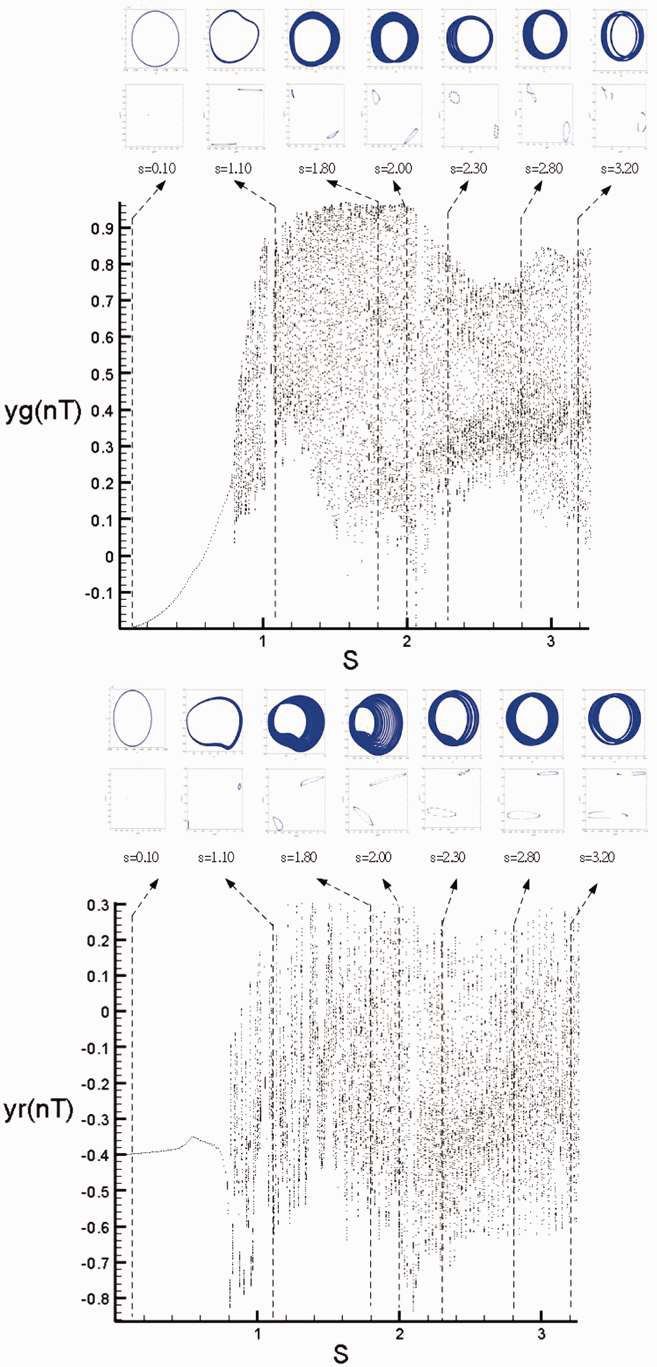
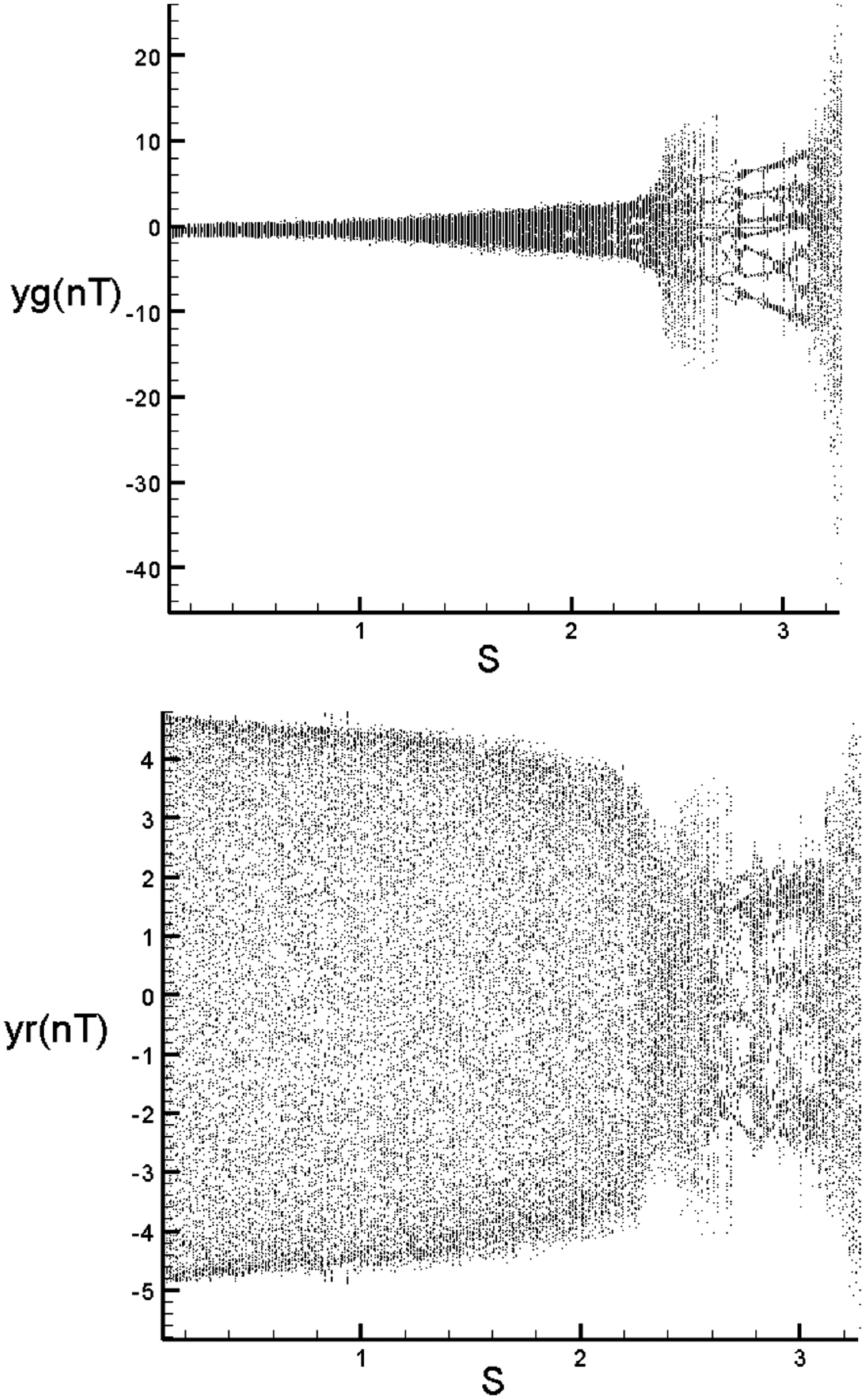
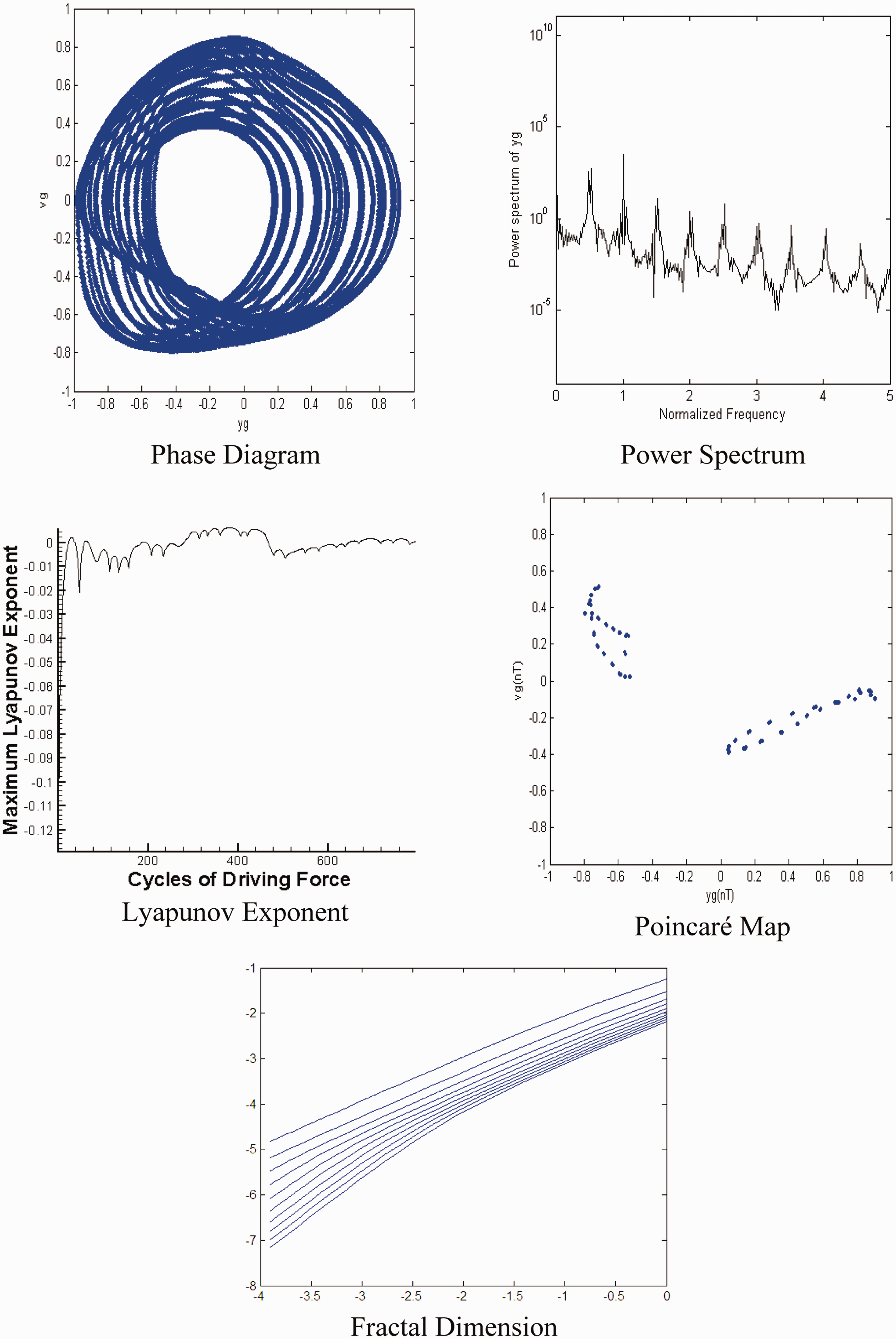
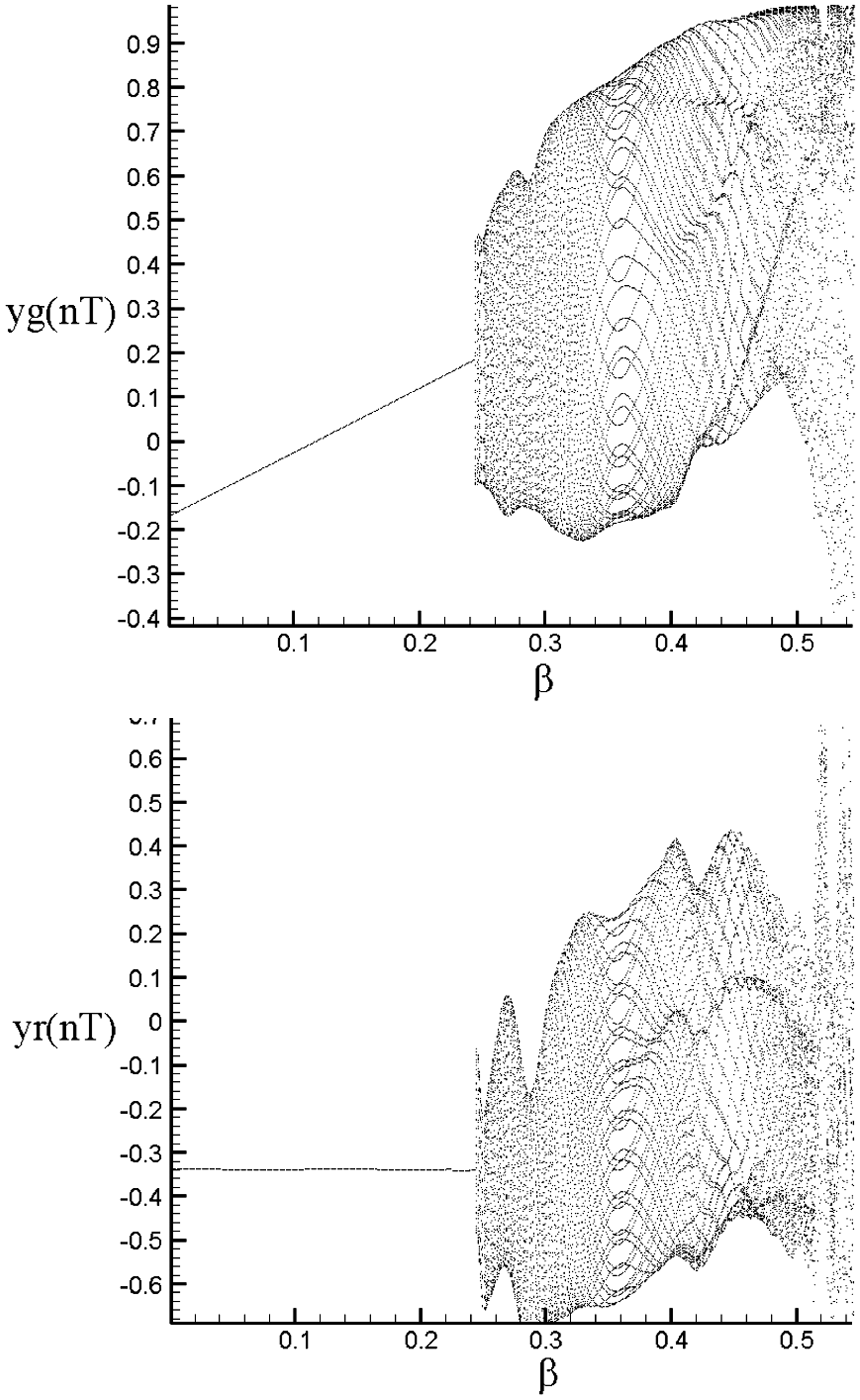
The dimensionless rotating speed ratio s is one of the most important parameters, and is commonly used as a bifurcation control parameter when analyzing the dynamic characteristics of the system. Accordingly, the dynamic behaviors of the current gear-rotor-bearing system were examined using the dimensionless rotating speed ratio s as a bifurcation control parameter. The bifurcation diagrams for the vertical displacement of gear center and rotor center against the dimensionless rotating speed ratio are provided first. Figures 4 and 5 are bifurcation diagrams of a gear-rotor-bearing system with and without HSFD, respectively. According to the simulation results of the bifurcation diagrams, as shown in Figures 4 and 5, they reveal that the dynamic behaviors will perform more regular dynamic behaviors, and the amplitudes are also smaller for the case with HSFD in such strongly nonlinear dynamic systems. The use of HSFD can impressively suppress non-periodic dynamic behaviors and reduce amplitude even at the higher rotational speeds. A bifurcation diagram with a HSFD case (Figure 4) shows that the geometric center of the gear and rotor in the vertical direction performs a synchronous 1 T-periodic motion at low values of the rotating speed ratio, i.e. s < 0.80, and then the non-periodic motion, or the so-called chaotic motion, can be found as the dimensionless rotating speed ratio is increased over s = 0.80. It can be seen that the vibration amplitude is larger for higher rotating speed than low rotating speed. With the increase of the rotating speed, dynamic characteristics are disorderly and behave with non-periodic or even chaotic responses. To illustrate the non-periodic motions more clearly, phase diagrams, power spectra, Poincaré maps, Lyapunov exponents, and the fractal dimension are applied to identify the onset of chaotic motions. We highlight a case from Figure 5 to show the dynamic motion of the geometrical center of the gear and geometrical center of rotor without HSFD, and show in Figure 6. It represents the dynamic behavior shown with phase diagrams, power spectra, Poincaré maps, Lyapunov exponents, and the fractal dimensions of pinion center at s = 1.80. The motions shown in the phase diagrams performed a disordered dynamic behavior; the power spectra reveals numerous excitation frequencies; the returning points in the Poincaré maps is the so-called geometrically fractal structures; the maximum Lyapunov exponent is positive, and the fractal dimensions are also found to be 1.33 for
Bifurcation diagrams of gear-rotor-bearing system with HSFD using dimensionless rotating speed ratio, s, as bifurcation parameter.
Bifurcation diagrams of gear-rotor-bearing system without HSFD using dimensionless rotating speed ratio, s, as bifurcation parameter.
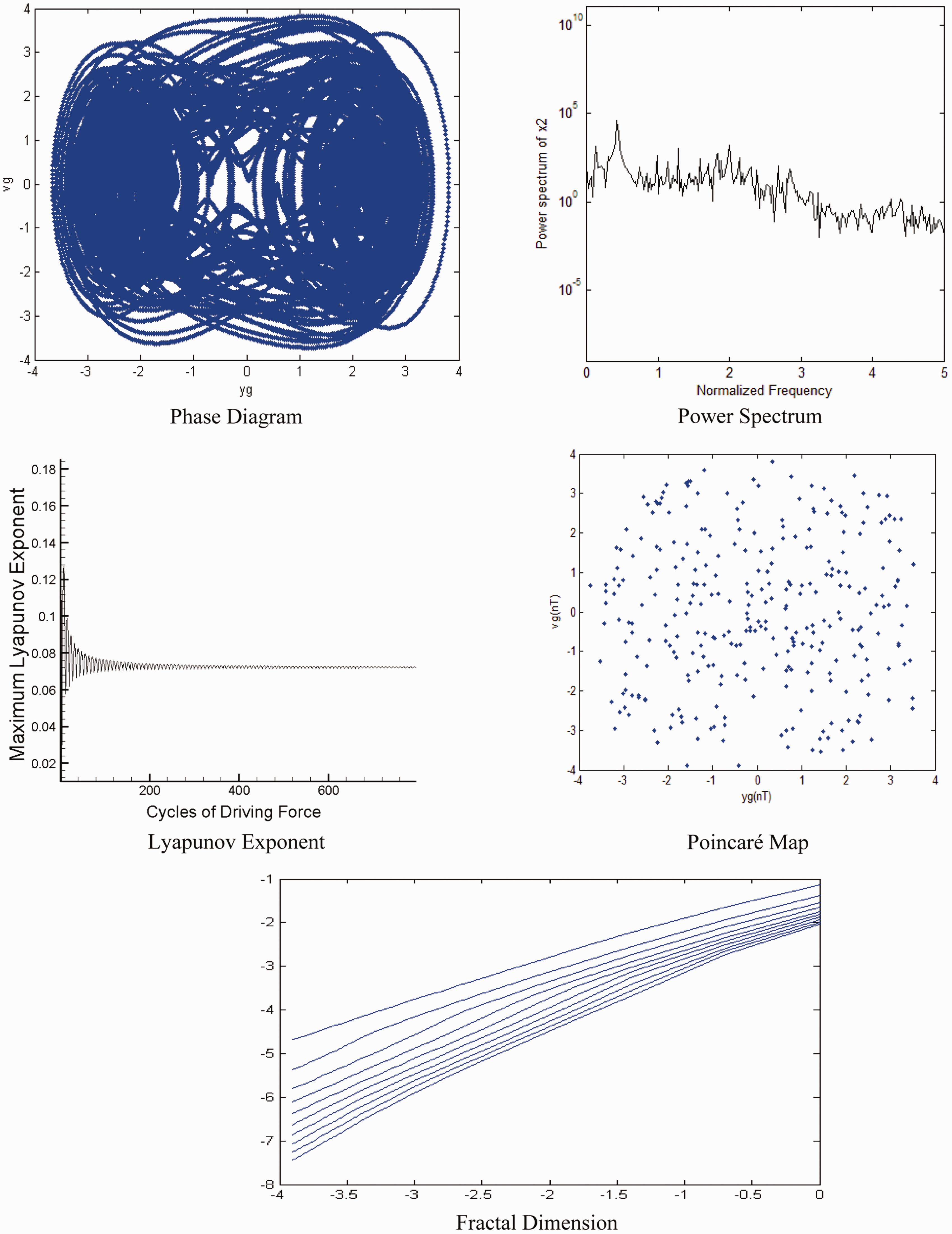
Simulation results obtained for gear-rotor-bearing system without HSFD and s = 1.8
The damping coefficient is also an important control parameter for observing the dynamic responses of the vibration system. From a physical point of view, the presence of damping coefficients in the vibration system will cause them to become a dissipative system. Figure 7 shows the bifurcation diagrams of gear geometric center and rotor geometric center with HSFD using a dimensionless damping coefficient,
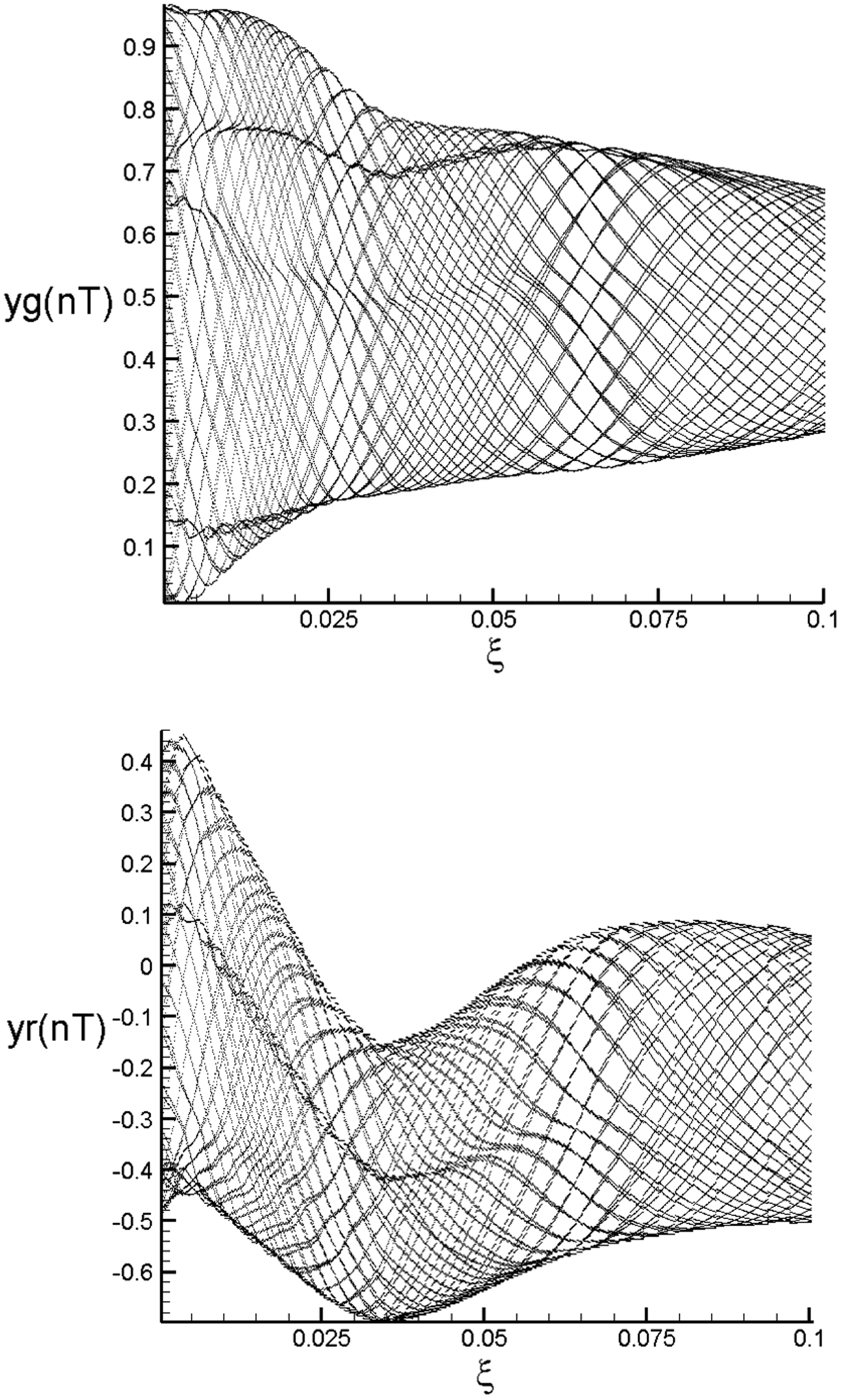
Bifurcation diagrams of gear-rotor-bearing system with HSFD using dimensionless damping coefficient,
Simulation results obtained for gear-rotor-bearing system with HSFD and
The dimensionless unbalance coefficient also plays an important role to study the dynamic response of the many rotating machineries. Therefore, it is valuable to study the various dynamic characteristics of a system for diagnosing some dynamic characteristics and faults by using an unbalance coefficient as the control parameters to plot the bifurcation diagrams. Figure 9 shows the bifurcation diagrams of the geometric center of the gear and rotor with HSFD using the dimensionless unbalance coefficient as a bifurcation parameter. It can be seen that the system response exhibits periodic motion at the interval of
Bifurcation diagrams of gear-rotor-bearing system with HSFD using dimensionless unbalance coefficient,
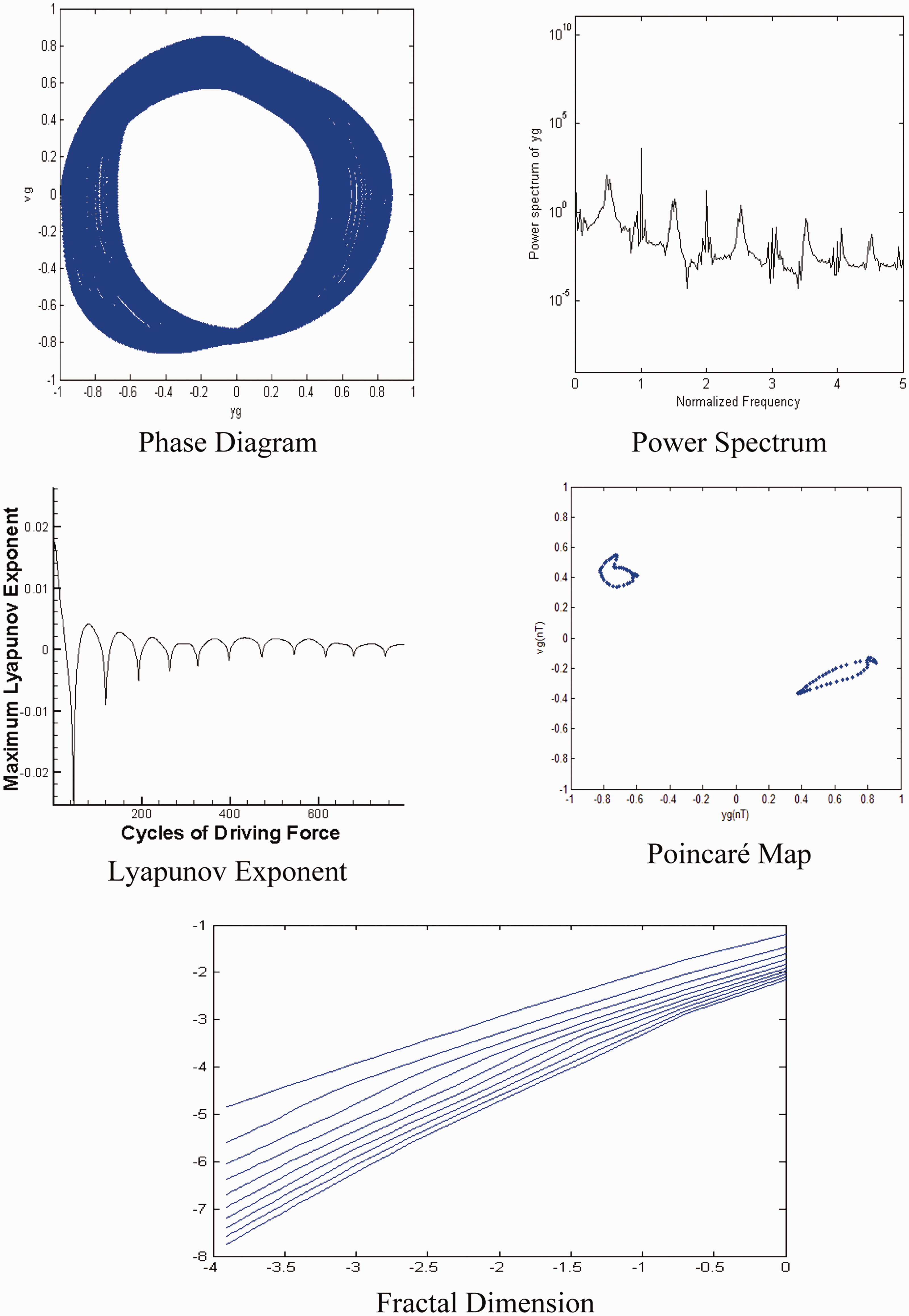
Simulation results obtained for gear-rotor-bearing system with HSFD and
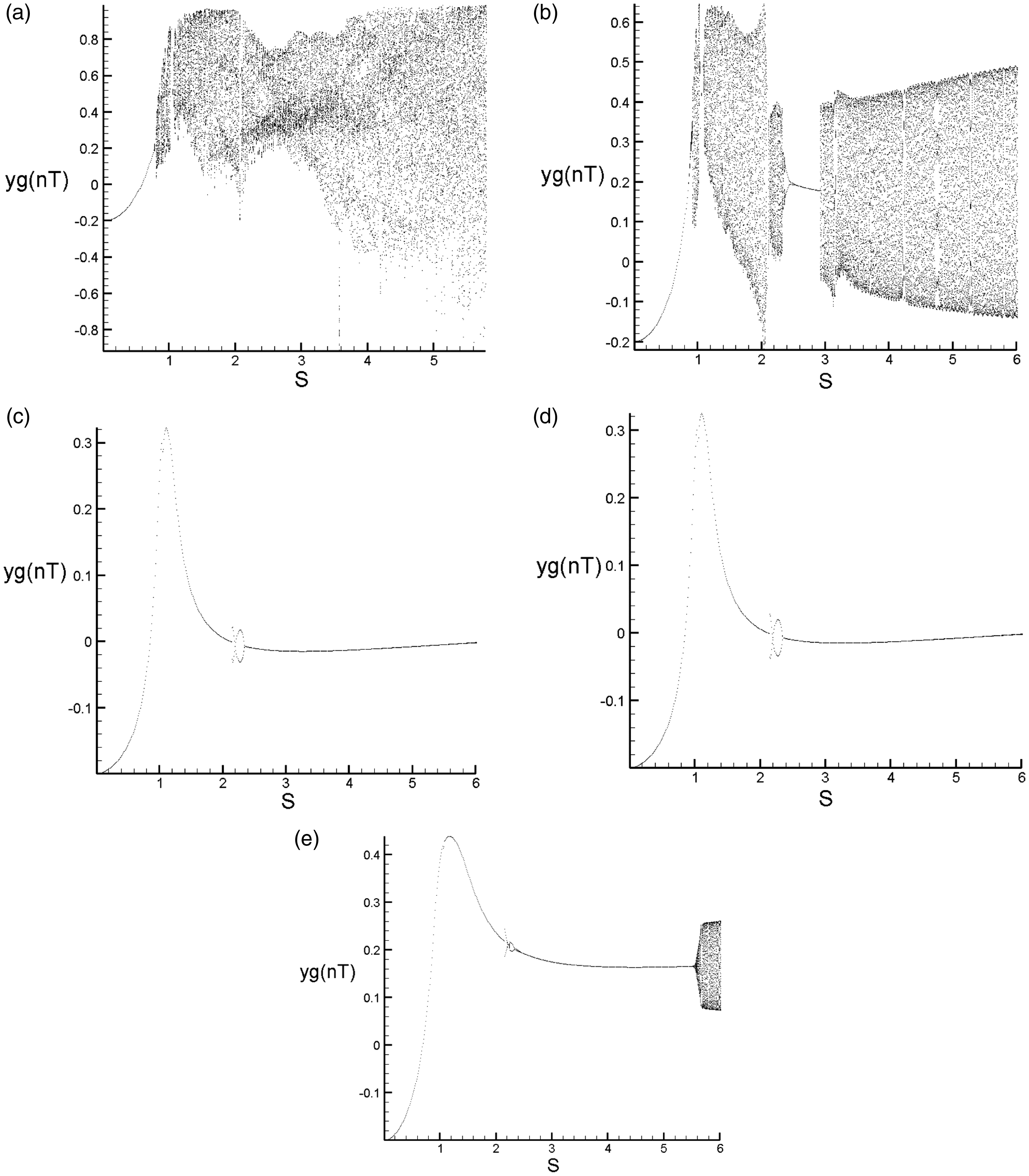
Comparison of bifurcation diagrams of gear geometric center using dimensionless rotating speed ratio, s, as bifurcation parameter with different values of
With hydraulic active control
The initial state of the retaining spring is given to be
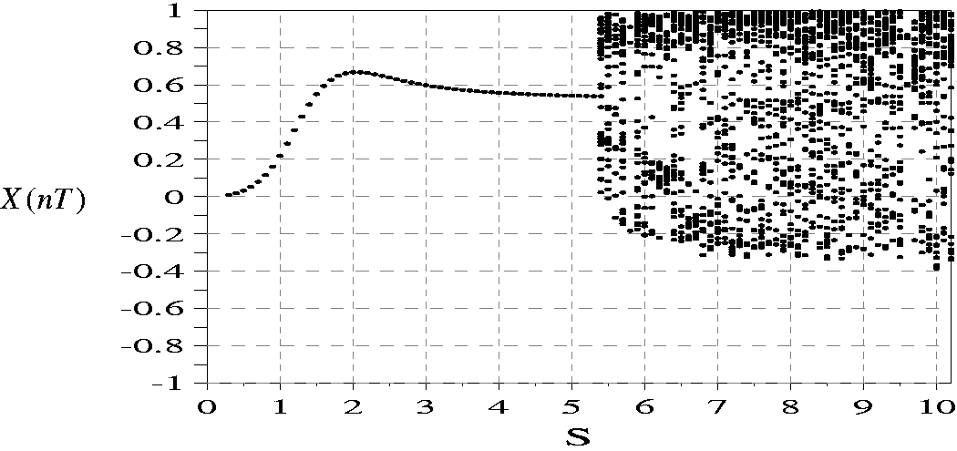
The bifurcation diagram of dynamic trajectory with Kp = 0.01 and Kd = 0.01.
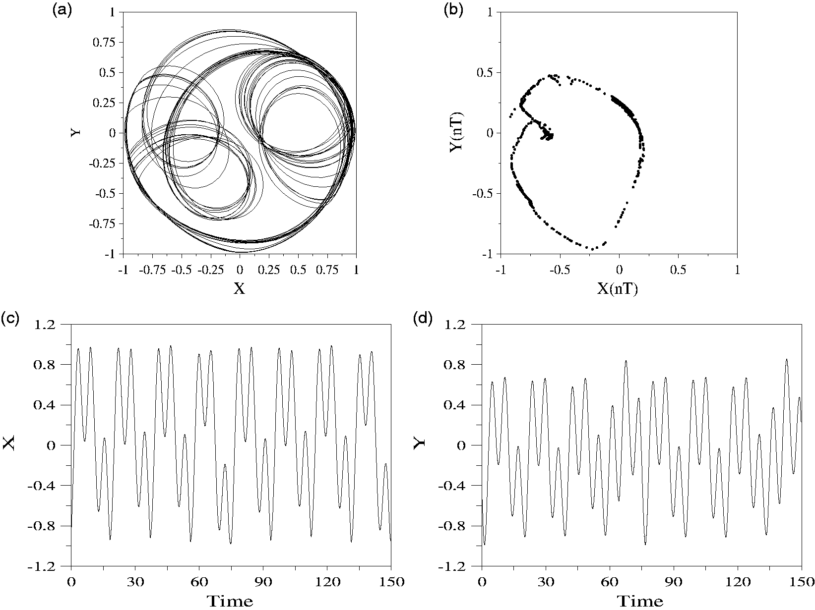
Aperiodic motion of rotor center at s = 6.0 with Kp = 0.01 and Kd = 0.01; (a) Rotor trajectory; (b) Poincare’ map in X(nT)-Y(nT) plane; (c), (d) Time response of rotor trajectory.
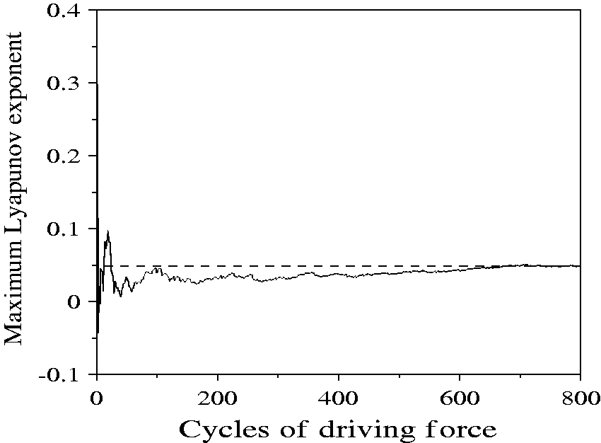
The maximum Lyapunov exponent of rotor trajectory plotted as a function of the number of drive cycles at s = 6.0 with Kp = 0.01 and Kd = 0.01.
The time response of
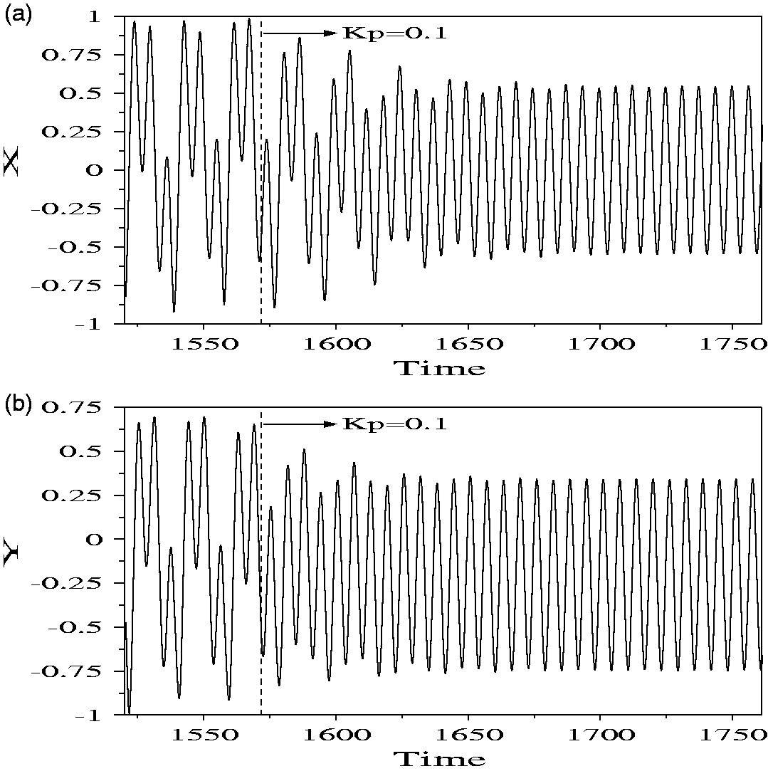
The time responses of rotor trajectories at s = 6.0 with Kp = 0.01 changes to Kp = 0.1 from non-dimensional time
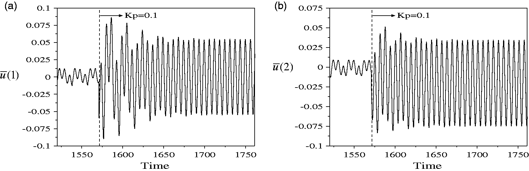
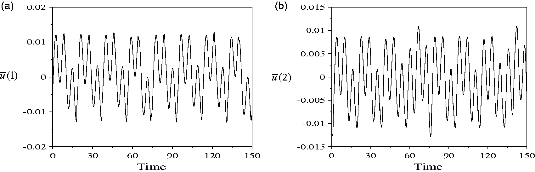
The time responses of
Conclusions
The numerical analysis of the nonlinear dynamic response of a gear-rotor-bearing system with nonlinear oil film force, nonlinear rubbing force, and gear meshing force is proposed in this study. The dynamic responses of the system are analyzed with reference to its dynamic trajectory, power spectrum, Poincaré maps, bifurcation diagram, maximum Lyapunov exponent, and fractal dimension. The bifurcation parameters of the dimensionless rotational speed ratio, the dimensionless unbalance parameter, and the dimensionless damping coefficient are used to study the nonlinear dynamic characteristics of the gear-rotor-bearing system. It can be observed that very rich aperiodic and chaotic motions can be found in the system. In this study, no general way of entering chaos was found (1 T => 2 T => 4 T => 8 T => 16 T => 32 T … => chaos or period => quasi-period => chaos). The authors also demonstrate that HSFD can suppress irregular dynamic behaviors and reduce the amplitude of rotating machines. In summary, the numerical results presented in this study provide a detailed understanding of the nonlinear dynamic responses of a gear-rotor-bearing system with some nonlinear effects. The numerical results will provide some useful viewpoints in designing those types of systems so that the chaotic behavior can be avoided, and thereby reduce the amplitude of vibration within the system, or even extend the life of the system. The authors have also proved that HSFD can be used to suppress the irregular or undesired vibrations found in the rotating machines.
Footnotes
Declaration of conflicting interests
The author(s) declared no potential conflicts of interest with respect to the research, authorship, and/or publication of this article.
Funding
The author(s) received no financial support for the research, authorship, and/or publication of this article.