
Abstract
In the development of automation industry, external force detection/monitoring is essential for the safety of human and machines. To detect or measure these forces easily, a static loading sensor is required. However, commercially available sensors are too bulky and cause installation difficulties in automated machines. A piezoelectric element is an electro-mechanical component wildly used for actuator sensing or harvesting applications. In this paper, a 10 N capacity thin piezoelectric force sensor is designed and tested for external static load detection. This paper considers that larger strain made by an external force on a proposed piezoelectric sensor generates higher voltage, thereby increasing its force estimation accuracy. Meanwhile, in most piezoelectric force sensors, a cantilever beam mechanism is usually adopted for its simple structure; however, large deformations seen in cantilever piezoelectric sensors are not proportional to its measuring accuracy nor force bearing capacity. Therefore, in this paper, an amplified trapezoidal shape mechanism is designed to convert external vertical load into horizontal displacement deformation in order to obtain higher voltage generation. The Taguchi optimization design method is proposed to analyze the key factors that affect the amplified mechanism design of the piezoelectric sensor. Moreover, static loading force applied on a piezoelectric component generates constant voltage that eventually decreases with time. This is because of its internal electric impedance property, which causes difficulty in static loading force estimation. To represent the theoretical model of the static force estimation in this paper, a chain scattering description matrix of a two-port network was proposed to represent the electric impedance in relation to the mechanical properties’ variation. The measured results demonstrate the accuracy of the proposed theoretical method which implies that the external force can be estimated by measuring its electric impedance variation, particularly the shift in resonance frequency Therefore, based on the developed theoretical model, a driving voltage with fixed frequency can measure its electric current in the same time, thereby achieving the external force monitoring technology.
Introduction
With recent trend in automation technology development, the requirement for static force sensors has been on a rapid increase. However, current commercially available sensors were made by a strain gauge, which have the disadvantage of large dimension for its sufficient deformation which will result in difficultly installing on existing automated machines. As a result, a thin loading force sensor using piezoelectric materials is proposed in this paper. Considering that the piezoelectric material is a hard and brittle ceramic material, most of the piezoresistive force sensors are mostly designed as a cantilever beam structure with insufficient deformation space which result to a small force measuring range. In order to achieve a large loading force measurement using a smaller dimension, an amplified trapezoidal shape mechanism is designed to convert external vertical load into horizontal displacement deformation and can produce a sufficient strain on the piezoelectric material without large deformation space. To achieve the suitable amplified mechanism design, Taguchi optimized design method is used to analyze important design parameters that affect sensor performance. The analysis results aided the design of an optimum performance thin piezoelectric sensor for large loading force measurement with limited size constraints. Moreover, the experimental results verify the effectiveness of the proposed sensoring method. According to the amplified mechanism design, the proposed piezoelectric sensor has the advantage of smaller dimension and can be installed on current automated machines easily.
Thin piezoelectric sensor for static loading force
Piezoelectric material
A material with piezoelectric effect is a piezoelectric material, with reversible conversion between mechanical and electrical energy. 1 The direct piezoelectric effect refers to electric polarization produced by mechanical stress and usually used in sensoring application such as force sensors and accelerometers. Inversely, the material can generate strain when an electric field is supplied; this is referred as “converse piezoelectric effect.” It is extensively applied in actuators like ultrasonic motors and piezoelectric stages. 2 Shown in Figure 1 are these two effects.
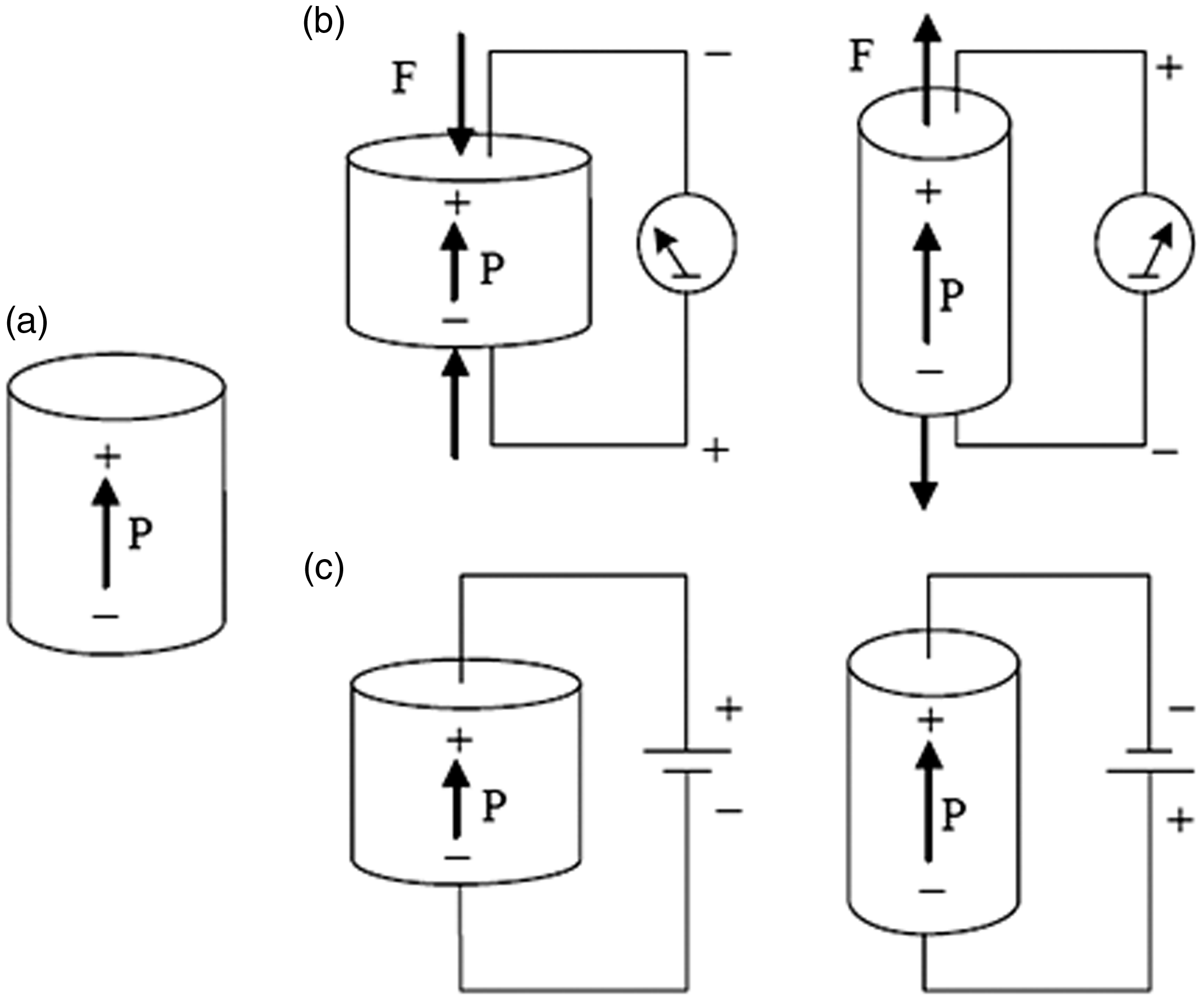
Piezoelectric effect: (a) original dimension, (b) direct piezoelectric effect and (c) converse piezoelectric effect. 1
Proposed piezoelectric sensors
In order to reduce the size of a traditional loading force sensor of 10 N measuring range, this paper proposed a piezoelectric sensor as shown in Figure 2. A piezoelectric plate, which is chosen as PZT-5H piezoelectric ceramic material, is stacked on a steel support plate. To support the large external loading, an amplified trapezoidal shape mechanism is designed to convert the external vertical loading force to a horizontal displacement deformation. Moreover, to achieve the force measurements easily, two amplified mechanisms, the upper and lower metal plates, were connected with the steel support plate to form the proposed loading force sensor. Its construction is illustrated in Figure 2.
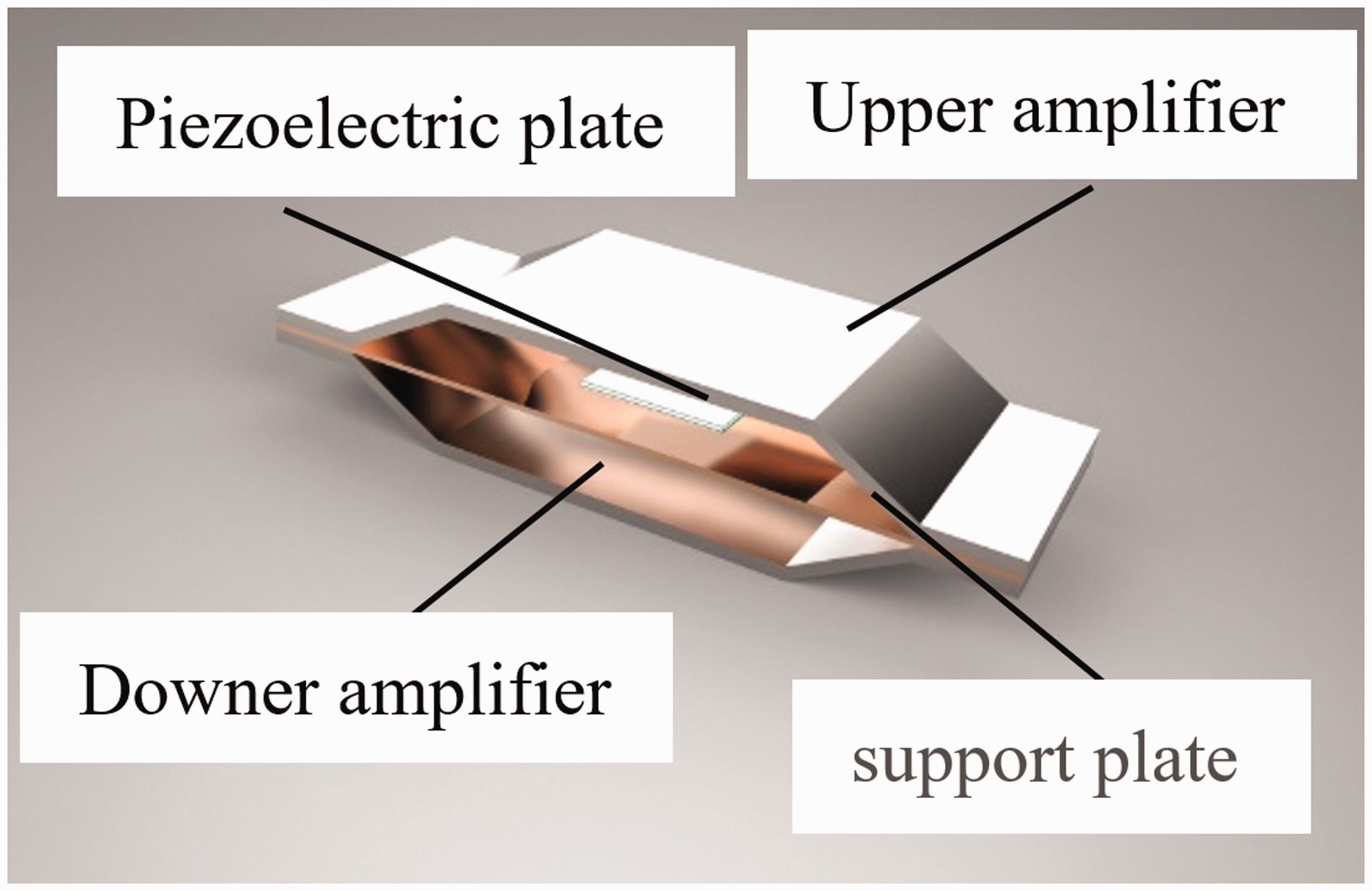
Proposed piezoelectric sensors.
Optimization design and theoretical model of static force estimation
Introduction of Taguchi optimized design method
Taguchi method is a statistical approach to optimize the process parameters and improve the quality of manufactured components. It was developed by Taguchi and Konishi in 1950. 3 To find the main function, a large number of experiments are needed to carry out the full-factorial design requirement, which will require a lot of development time. To overcome this problem, Taguchi suggested a specially designed method called the use of orthogonal array to study the entire parameter space with lesser number of experiments to be conducted. 4 According to the proposed orthogonal array, optimum control factor levels and its performance can be predicted by signal-to-noise (S/N) ratio, and the desired performance target can be achieved.
Optimization design of piezoelectric sensor
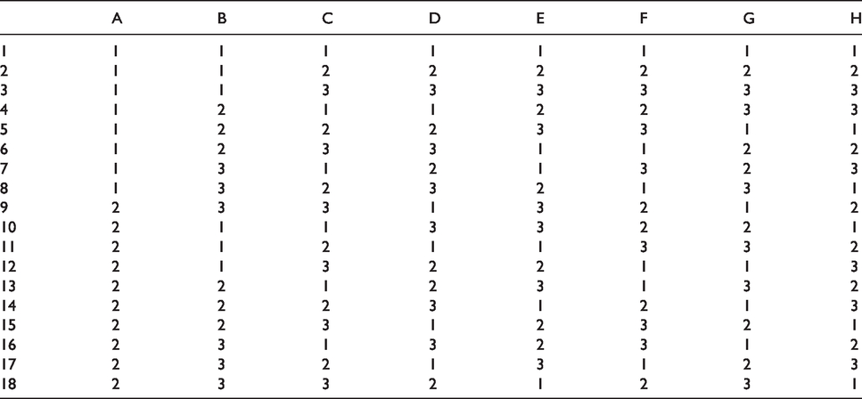
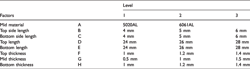
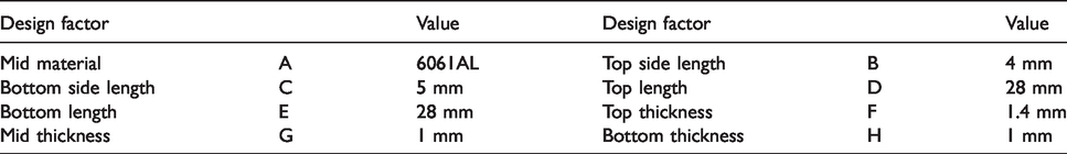
Taguchi method can be used to find performance affect factors with lesser number of experiments. In this paper, Taguchi method is proposed to calculate design factors for the amplified mechanism of the piezoelectric sensor, which can generate large strain in the same external loading and limited size constraints. To demonstrate the performance of the designed sensor and the proposed design method, a 10 mm thickness and 30 mm length of limited dimensions for a 10 N measure range (1 kg) is proposed. At first, an appropriate orthogonal array for conducting the experiments should be chosen to find the design parameters. In this paper, eight of the control factors affecting the piezoelectric sensor is considered, as illustrated in Figure 3. The suitable orthogonal array for experimentation is L18 array as shown in Table 1. According to Table 1, only 18 of experimental combinations were provided to estimate the optimum performance with suitable control factors. According to the proposed design parameter and its suggestion value, as shown in Table 2, each experimental condition can be decided depending on the corresponding row of proposed orthogonal array as shown in Table 1. For example, in the first experiment, the material of support plate is chosen as 5020 Aluminum alloy (A1) and its thickness is 0.5 mm (G1); top side length, top length of upper amplifier, and the thickness are chosen as 4 mm (B1), 24 mm (D1), and 1 mm (F1), respectively. Similarly, the bottom side length, bottom length, and bottom thickness of downer amplifier are 4 mm (C1), 24 mm (E1), and 1 mm (H1), respectively.
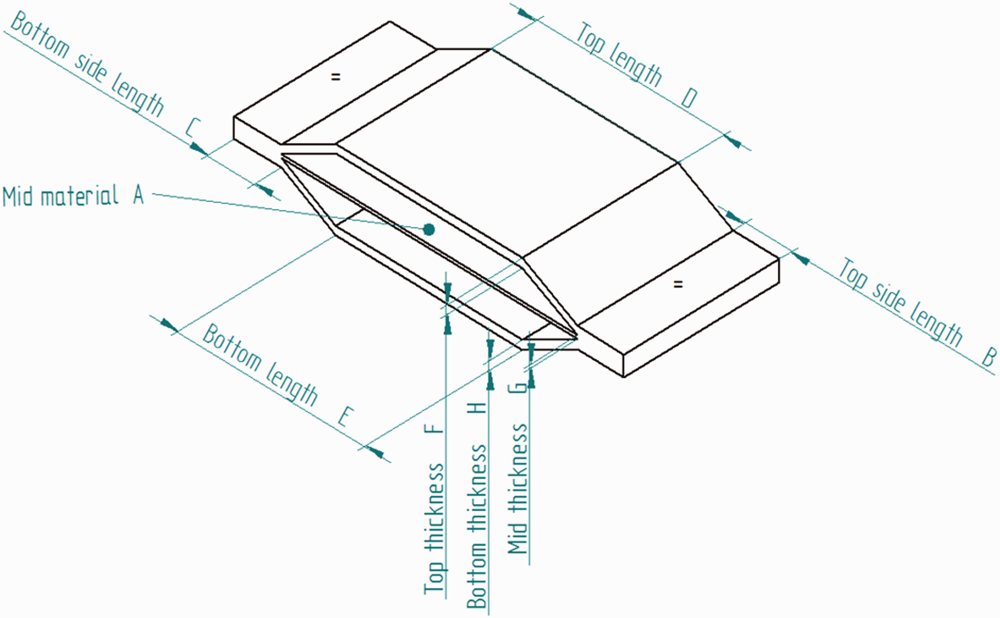
Control factors of the piezoelectric sensor.
Proposed L18 orthogonal array.
Levels of control factors.
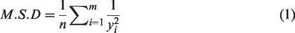
In Taguchi design method, the influence of each control factors represents as noise disturbance in the system. In this paper, the same conditions of external loading force generated larger strain. The design target of the larger-the-better was adopted in this paper, and according to experimental results for orthogonal array, the S/N ratio of each control factors is calculated as

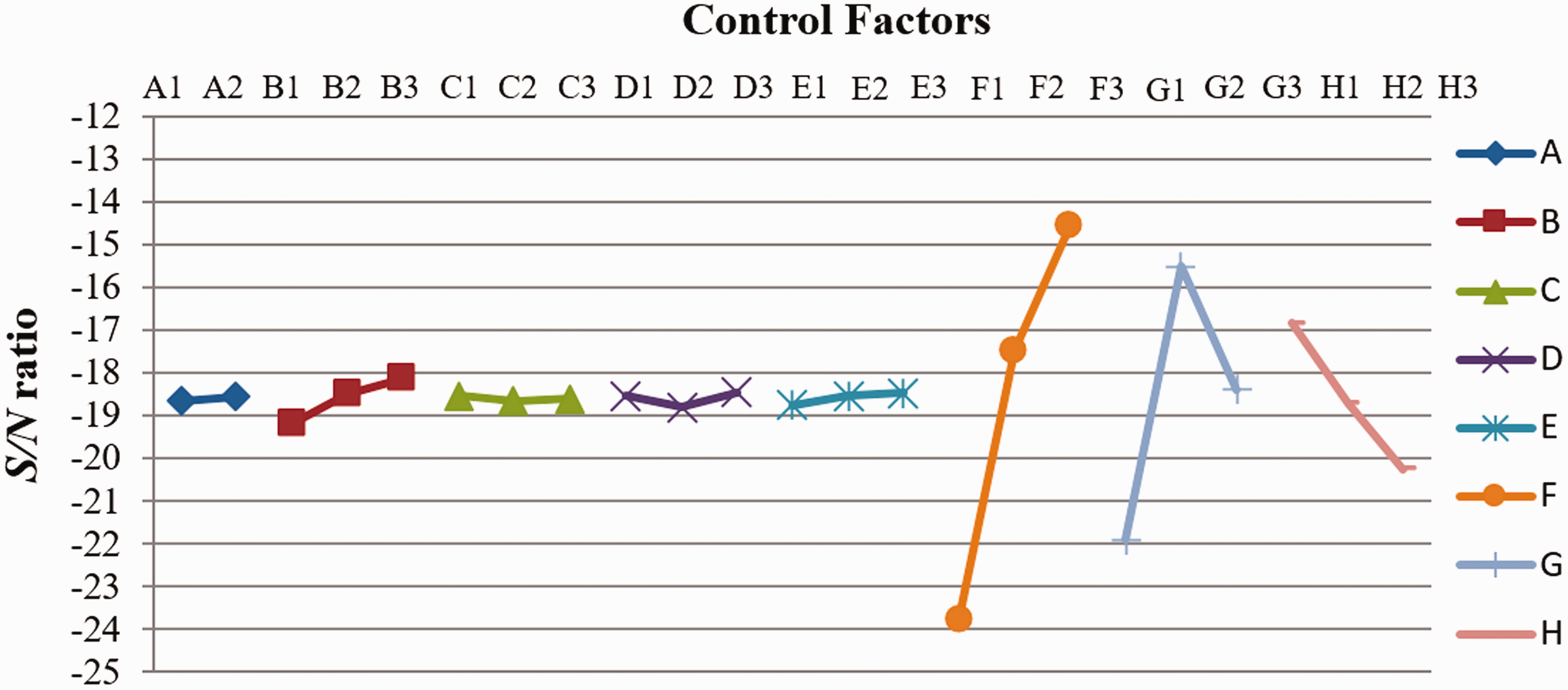
S/N ratio of each control factor.
Based on the Taguchi design method, listed in Table 3 are the optimized design dimensions of the piezoelectric sensor. Figure 5 shows the performance comparison between the first experiment and optimization design of control factors, which represents the strain distribution with 100 N loading force application. It can be found that the maximum deformation from –4 to 4 µm in the optimization design is better than the first experiment’s factor from –0.5 to –3.5 µm.
Optimization value of control factors.
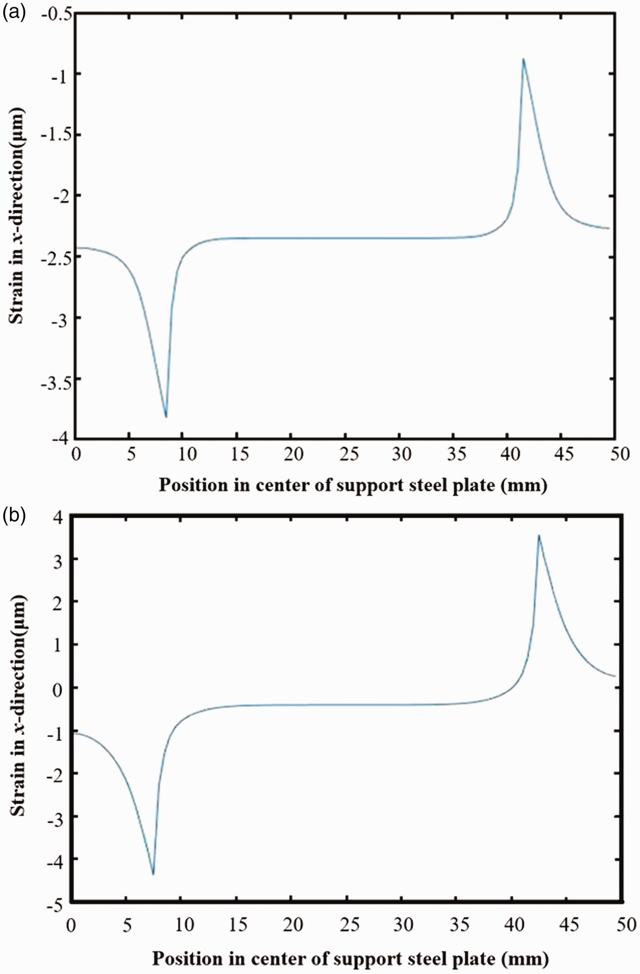
The performance comparison: (a) first experimental condition and (b) optimization design.
Theoretical model of static loading force estimation
According to previous descriptions, the proposed piezoelectric sensor has direct electro-mechanical conversion property of which external force converts into voltage output
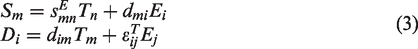
Equation (3) represents the constitutive equation of piezoelectric sensor behaviors. The mechanical and electric inputs are stress T and electric field E, respectively, whereas the generating mechanical and electric output is strain S and electric displacement D, respectively. The variable d is the piezoelectric coefficient;
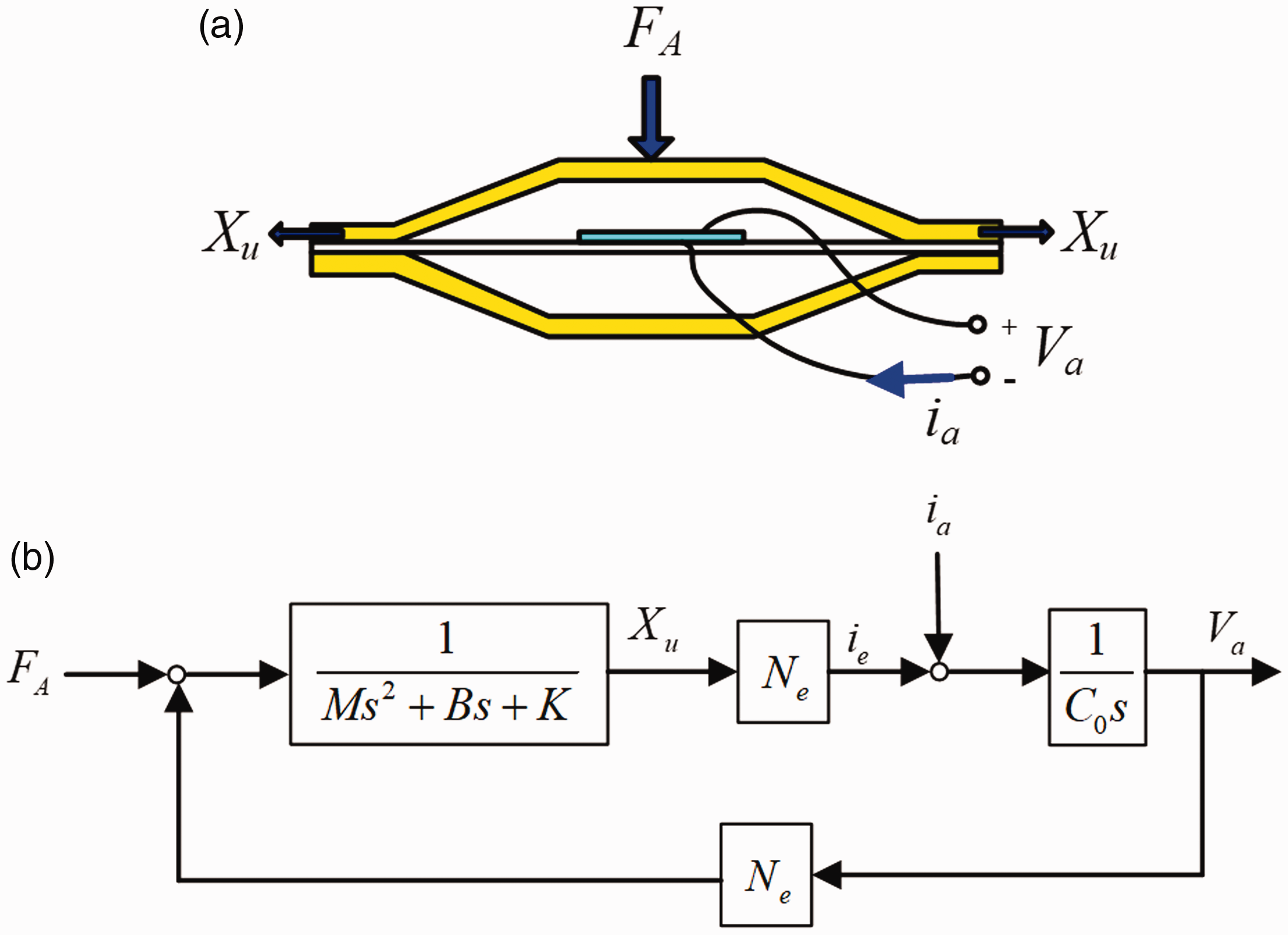
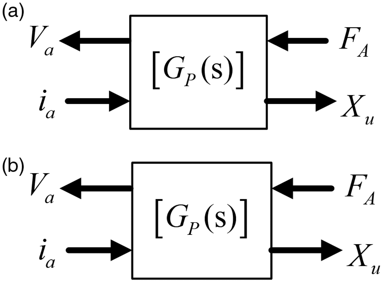
Observing equation (3), it shows that the input and output of the piezoelectric component can be electrical or mechanical signal. Observing the input and output of the proposed piezoelectric sensor in Figure 6(a), a dynamical external force FA applied on the proposed force sensor is the system input, which resulted in the deformation Xu. 5 To analyze the overall input–output behavior, a feedback block diagram representation is used as shown in Figure 6(b). It is found that the system’s mechanical relationship is equivalent to a mass-spring-damper model. In addition, the electric current ie can be converted from the deformation displacement caused by piezoelectric effect Ne to resist the outside electrical inputs ia. According to the internal electric capacitor property (C0), a voltage Va can be equal to the system output, and the generating voltage can also be converted into internal force to affect the system input, i.e. the external loading force by the piezoelectric effect N.
Theoretical representation of piezoelectric force sensor.
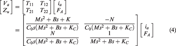
From the theoretical model shown in Figure 6, assume that there is no external force applied, the overall input–output relationships are represented in a transformation matrix [T] as shown in Figure 7(a). In addition, the function matrix with the Laplace form can be obtained by Mason’s rule as
The system input-output representation; (a) Transformation matrix, (b) Chain scattering matrix.
However, in the static loading force measurement, the initial force application generates constant voltage. Afterward, the voltage decreases with time with respect to its internal electric impedance property. This leads to static loading force estimation difficulty. In order to achieve accurate static loading force estimation, assume that the proposed piezoelectric sensor is a flexible mechanism, the external static loading force FA will cause a horizontal displacement deformation Xu, in which the relationship is as follows

From equation (5), the external force can be estimated by measuring the deformation according to the structure elastic modulus. However, the deformation will be feedback to become an internal current based on its electromechanical conversion efficiency. In addition, the deformation is difficult to measure for use in external force estimation. Therefore, in this paper, measured electric properties is used to analyze the mechanical property variation such as the external force. Specifically, the mechanical characteristics can be adjusted by using external electric circuit. In this paper, a chain scattering description (CSD) matrix of a two-port network, which is widely developed in the network circuits by a straightforward interconnection in a cascaded way,
6
is additionally proposed to analyze the external force related with electric characteristics. To analyze the electromechanical characteristic relationship, the electric and mechanical properties is defined as the input and output of the two-port network model, respectively, and represented in the right and left side of the CSD matrix as shown in Figure 7(b) and equation (6)


From equations (7) and (8), the characteristic function in each element of CSD matrix is as follows
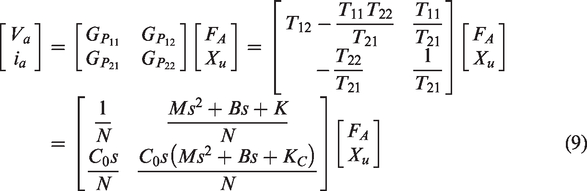
Observing equation (9), the right and left side of Gp individually represents the electrical and mechanical properties. According to the input–output relation of the CSD matrix, it is easier to analyze the electro-mechanical interaction during an external electrical or mechanical loading, applied without changing the original characteristic function of a single piezoelectric sensor using two-port network method, particularly in stability analysis for
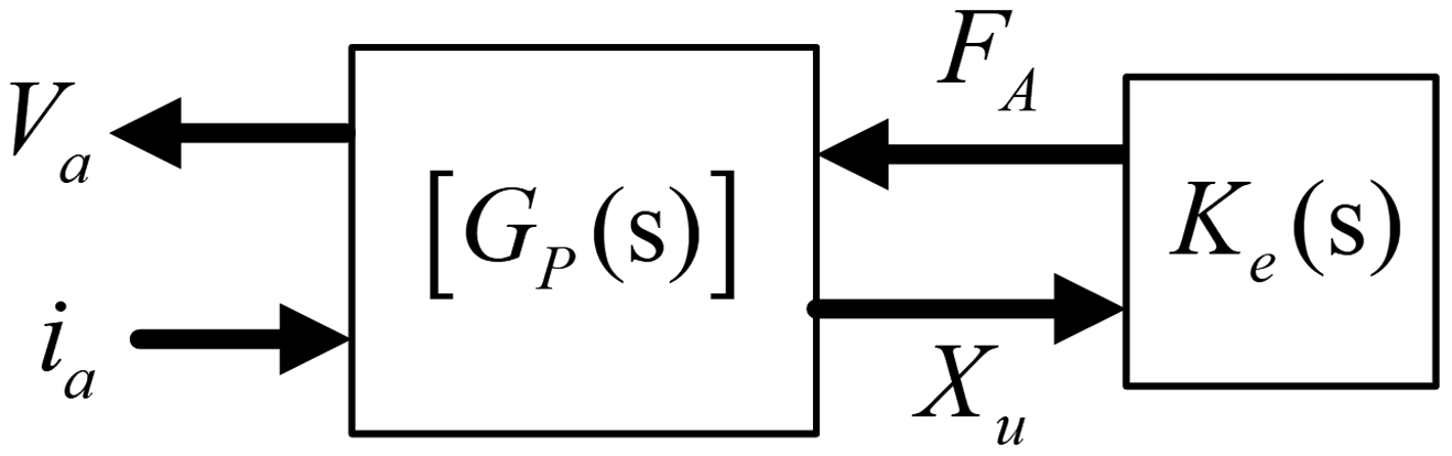
Representation in CSD form with external loading.
Observing Figure 8, the function describing the electro-mechanical interaction is as expressed using the CSD matrix, in which the electrical property function and the mechanical loading are defined below by signal flow in the anti-clockwise direction

Observing Figure 8, the right side of the electric property represents an electric impedance. Then the transfer function of electric impedance from ia to Va is given by CSDr (G, Ke)
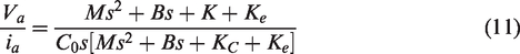
As mentioned previously, the static loading force will cause the variation of the structure stiffness and mechanical impedance, but it is difficult to measure the mechanical impedance in order to estimate the external loading. Observing equation (11), it can be found that the electric impedance is influenced by the mechanical stiffness variation. This is caused by the application of the external static force, which through its functional relationship can therefore be determined by the structure elastic modulus Ke. In order to use the electric impedance to determine the external loading, a resonance frequency 
Therefore, based on equation (12), the equivalent stiffness variation Ke with different external loading force is identified using the measured result, and the static force can then be estimated from the measured resonance frequency.
Measurement result of static loading force
The proposed load sensor manufactured using the optimized control factors is as shown graphically in Figure 9. In order to verify the piezoelectric sensoring principle, some standard test weights, such as 100, 200, and 500 g, were used as the external loading force applied on the proposed piezoelectric sensor. Based on electro-mechanical converted behaviors of piezoelectric component, a strain can convert into electricity. It means that the electric impedance can be changed by the variation of its mechanical properties such as stiffness. Therefore, to observe the electric impedance variation for different external load force, the shift of resonance frequency with lowest impedance value can be measured to verify the effectiveness of the proposed theoretical model. Therefore, in the proposed measurement structure, an external load is vertically applied on the proposed load sensor, and a corresponding electrical impedance is measured using the impedance analyzer. Furthermore, the external loading force can be estimated by observing the resonance frequency movement. Figure 10 represents the electric impedance measurement with different standard test weights from 0 to 800 g, respectively. Compared with the measured result, it is found that the resonance frequency will move from 1.65 to 1.61 kHz when external load weights of 0–800 g are applied on the sensor, and the impedance value of resonance frequency at different loads will not be affected. It shows that the external loading force can only affect the equivalent stiffness of piezoelectric device, but not affect the equivalent mass or damper. This corresponds with the assumed conditions of the proposed theoretical method as expressed in equation (11). In order to understand the piezoelectric sensoring principle, the equivalent stiffness variation Ke related with the resonance frequency is plotted as shown in Figure 11. Higher stiffness variation for heavier external load is observed. Therefore, in order to measure the shift of resonance frequency, a driving voltage with fixed frequency is proposed. The electric current is measured to estimate variation of the electric impedance, and the external force can be identified from the proposed theoretical model.
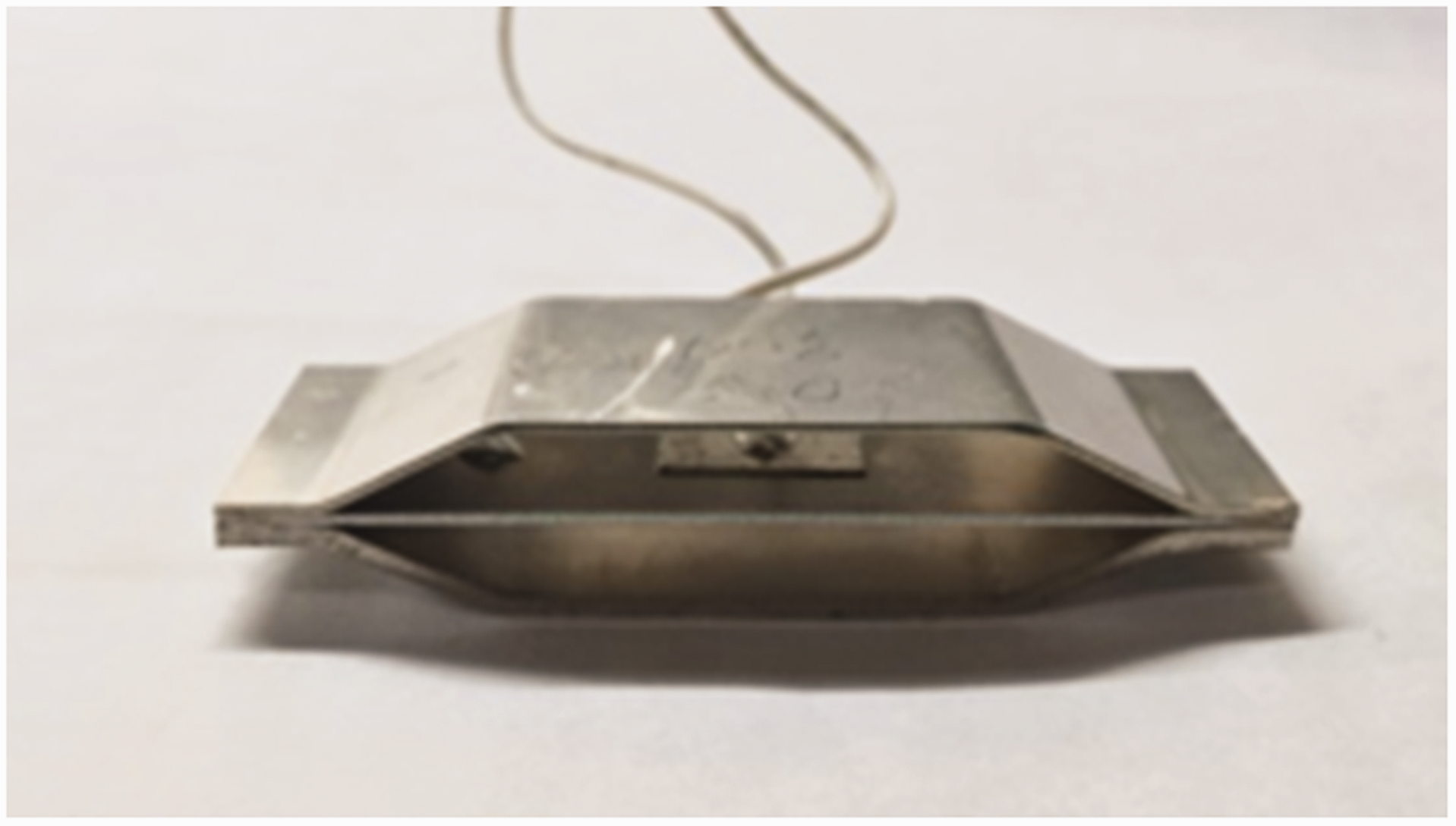
The graphic of piezoelectric force sensor.
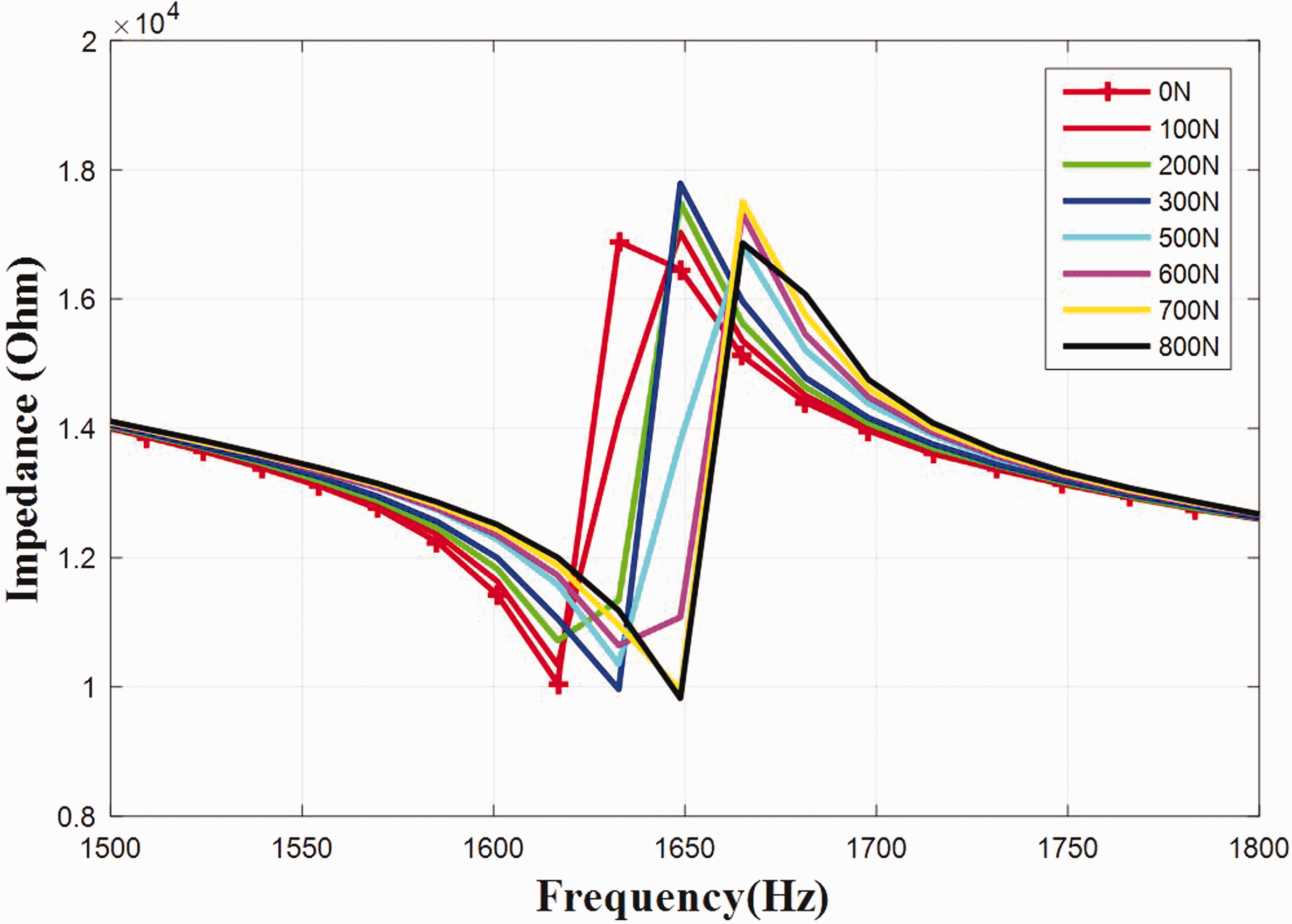
Electric impedance distribution with different loading.
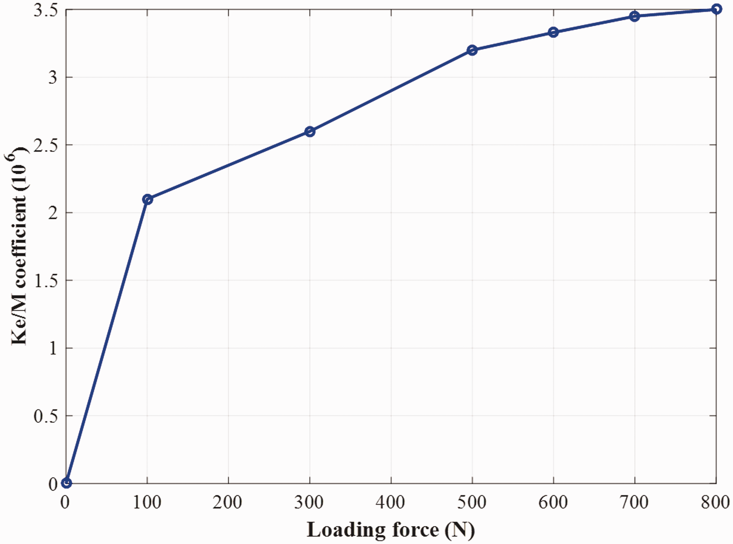
The calculation of equivalent stiffness Ke with different loading.
Conclusions
In this paper, the design of a thin static force sensor is proposed. The design process identified various factors that can affect the experimental results, such as the size, shape, and material of the sensor. In order to find the major control factors, Taguchi method is proposed to understand the design factors for the amplified mechanism of the piezoelectric sensor with lesser number of experiments, thus determining the optimized value of each design factor. Moreover, since the piezoelectric material possesses direct electro-mechanical conversion characteristic, a CSD matrix of a two-port network was evaluated to describe the relationship between the electric and mechanical properties. To verify the piezoelectric sensoring principle, different standard test weights from 0 to 800 g were vertically applied on the designed loading sensor, a corresponding resonance frequency emerged within 1.65 to 1.61 kHz range. Finally, the accuracy of the proposed theoretical method is demonstrated, and the external loading force can be estimated by using a driving voltage with fixed frequency. Also, it is shown that the external static load can be identified from the electric current variation.
Footnotes
Declaration of conflicting interests
The author(s) declared no potential conflicts of interest with respect to the research, authorship, and/or publication of this article.
Funding
The author(s) disclosed receipt of the following financial support for the research, authorship, and/or publication of this article: This research is partially supported by the Ministry of Science and Technology, Taiwan, R.O.C. under Grant no. MOST 106–2218-E-218–006 and MOST 107–2221-E-218–031.