
Abstract
The influence of damping plates on structural vibration, noise and the contribution of the box girder bridge panels was analysed using the model test and numerical calculation methods. In this paper, a 1/10 scale box girder model test system was designed and constructed using a simply supported 32 m box girder from the Beijing–Shanghai high-speed railway as a prototype, and damping plates were laid on the box girder web side after the model was verified as being similar to the prototype by means of a series of model tests. The effects of the damping plates on the reduction of the structural vibration and noise were evaluated according to scaled model acoustic tests. In addition, the influence of the damping plates on the sound contribution of the panel was analysed based on the transient boundary element method. The study shows that the damping plates had an obvious vibration reducing effect on the concrete box girder, though their noise reduction properties were less than ideal. The vibration level reduction and time–history noise level reduction were kept within 10.2–29.5 dB and around 1.0 dB (A), respectively. The noise would decrease to its lowest value at 250 Hz – down to 4.0 dB. The damping plates were helpful in effectively reducing the sound power contribution and the sound pressure contribution of the concrete panel. At the peak frequencies of 17 Hz and 251 Hz, the sound power contributions of the panel on the damper side were reduced by 3.4 dB and 3.7 dB, respectively, compared with the normal side, while the sound pressure contributions on the panel decreased by 4.9 dB and 4.2 dB, respectively.
Introduction
With the continuously increasing density of high-speed railways and urban rail transit networks, as well as their gradually increasing running speeds, the resulting ambient vibrations and associated noise problems have become more and more severe. Large numbers of box girder bridge are found in high-speed railway and urban rail transit networks. When the train passes through the viaduct, it will cause the box girder structure to vibrate, and this vibration energy will be transmitted to the ground, and this vibration will reach the foundation of the building and induce the secondary vibration of the building. In addition, the radiated structural noise from the box girder is characterised by low frequency (LF), slow attenuation and wide influence coverage. To a certain extent, this will cause health problems for those who are working and living in this environment long term. 1 Therefore, the study of reduction of structural vibrations and noise on the railway box girder bridge has an important theoretical value as well as being of great engineering significance.
Noise problem resulting from box girder bridge structures on elevated tracks relates not only to the bridge itself but also to the track/vehicle structures and is therefore a very complicated coupling vibration problem. 2 At present, analysis on vibrations and sound radiation of box girder bridge structures is mostly carried out using analogy methods, numerical analysis, semi-analytical methods and field test methods. Numerical methods are an important way of calculating noise in complicated structures. Common numerical methods include the finite element method, infinite element method, boundary element method and statistical energy analysis method, as well as combined calculations using several different numerical methods. The International Union of Railways (UIC),3–5 Kurzweil 6 and Hardy 7 obtained an empirical equation for predicting bridge noise based on a large number of field tests. Li et al., 8 Zhang, 9 Gao 10 and Liu and Daiyan 11 focused on the noise analysis in a concrete box girder structure based on the finite element and boundary element methods, respectively. Remington and Wittig, 12 Thompson 13 and Poisson and Margiocchif 14 predicted the bridge sound radiation based on the statistical energy analysis method and verified the feasibility of this method in predicting structural noise in bridges. Ngai and Ng 15 measured the structural noise and vibrations of elevated box girders and found that when a train was running at 140 km/h, bridge vibrations and noise occurred mostly in the 20–157 Hz range. Coherence analysis also showed that the structural noise radiation was mainly caused by the local high-frequency bending vibration mode of the box girder.
The control of structural noise in bridges has always been at the forefront of research into structural acoustics and control and is a widely recognised challenge for researchers throughout the world, since no effective solution has been presented to date. Generally, noise can be controlled through three aspects, i.e. the noise source, the propagation route and the receiver. However, for rail transit, vibration and noise reduction measures are always taken considering the noise source. This includes using elastic fasteners or low-stiffness track structures such as elastic supporting blocks, trapezoidal sleepers or floating slab tracks; the working principle of which is that the vibration energy transmitted to a bridge structure when a locomotive is passing by can be decreased through improving the elasticity of the track structure in order to reduce its secondary noise. Nelson, 16 Wang et al. 17 and Harrison et al. 18 analysed the influence of fasteners on the vibration and noise of bridge structures. Gao et al. 19 tested the noise of an elevated bridge on line 5 of the Beijing subway and carried out a contrast analysis on the bridge noise when a train passed the trapezoidal sleeper track and common slab track. The test results showed that the vibration and noise reduction effect of a trapezoidal sleeper track was significantly better than that of a solid bed track. The speed response within the LF range could be decreased by over 70%, and the A-weighted secondary structural noise could be decreased by up to 24 dB (A).
The reduction in structural vibration on a track is helpful in effectively mitigating the transmission of vibration energy to the bottom bridge structure, decreasing the vibration response. 20 However, severe track irregularity might be caused at the same time, resulting in higher vehicle vibrations and wheel-rail noise. Dampers are a new technology that are now being applied to simple structures in cars, ships, submarines, satellites and also in rail transit applications. However, an actual elevated track-box girder is characterised by its complicated structure and wide noise frequency range, making theoretical solutions impractical. Liu 21 studied the influence of a constrained layer damping in controlling the vibration and noise from a composite railway bridge using the modal strain energy and statistical energy analysis methods, and field tests on the vibration and noise from a (32 + 40 + 32)m steel–concrete composite bridge induced by EMUs was carried out before and after constrained layer damping treatment.
Based on the 32 m box girder from the Beijng–Shanghai high-speed railway, a 1/10 box girder model system was established for this paper, and the influence of the damping plate on vibration- and noise-reduction were analysed by contrast test on the small scale model. In addition, the influence of the damping plates on the sound contribution of the panel was analysed based on the finite element and transient boundary element methods.
The model design, build and similarity verification
Based on the similarity theory and the model design analysis, taken the Beijing–Shanghai high-speed railway simply supported box girder structure as the prototype, a 1/10 box girder bridge scale model was designed and constructed for the study of the vibration and noise transmissibility characteristics.
22
The finished production and the dimension of the box girder scale model are shown in Figure 1. The elastic modulus and the density were obtained by the cube strength and density test, the results are
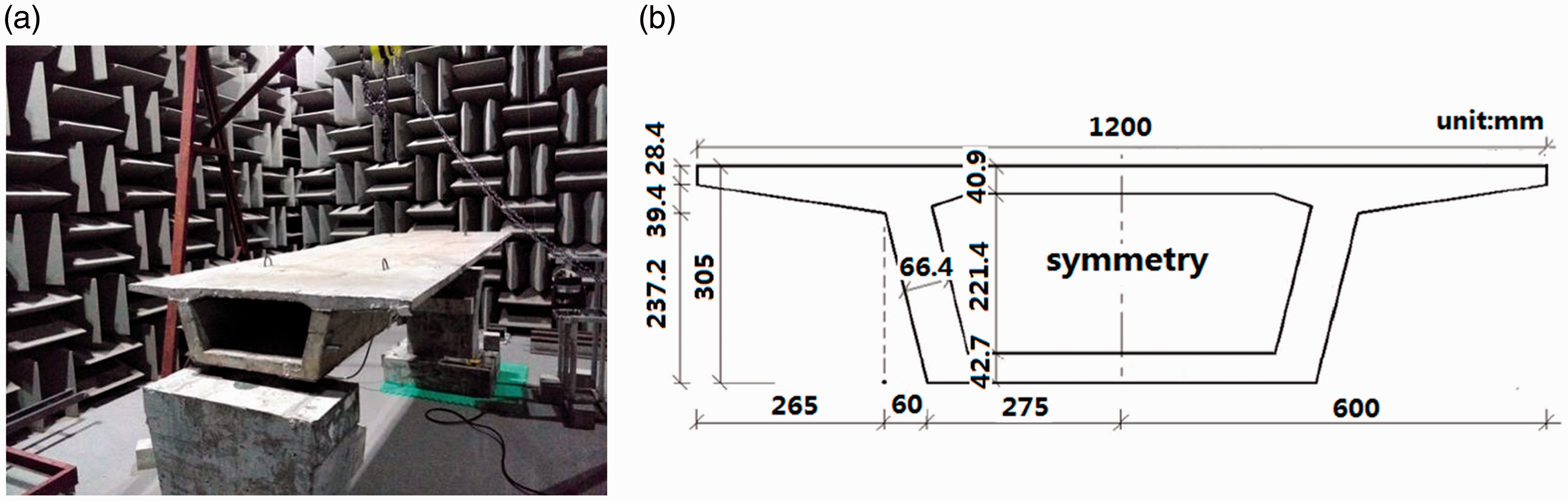
The box girder scale mode: (a) the finished production of the scale model and (b) the dimensions of the scale model.
The dynamic similarity ratio at the elastic stage.
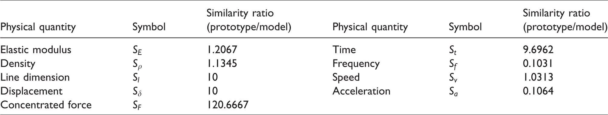
In order to ensure the similarity of vibration and noise between the prototype and the designed scale model, modal test is adopted. During the testing, the 1/10 scale model is fixated on the top of the bridge pier so as to measure the modal frequency of the scale model in the constraint conditions. A random burst signal is adopted as the excitation signal, and the flange of the scale box girder is chosen as the excitation point. The modal testing equipment includes the LMS SCADAS, PCB356A16 three-direction acceleration sensors (sensitivity: 100 mV/g, range: ±50 g, frequency response range: 0.3–6 kHz), the vibration exciter, laptop, and so on (see Figure 2).
Constraint modal experiment: (a) modal test system, (b) locations of collection points and excitation point, (c) data acquisition unit (LMS SCADAS) and (d) acceleration sensor and force sensor.
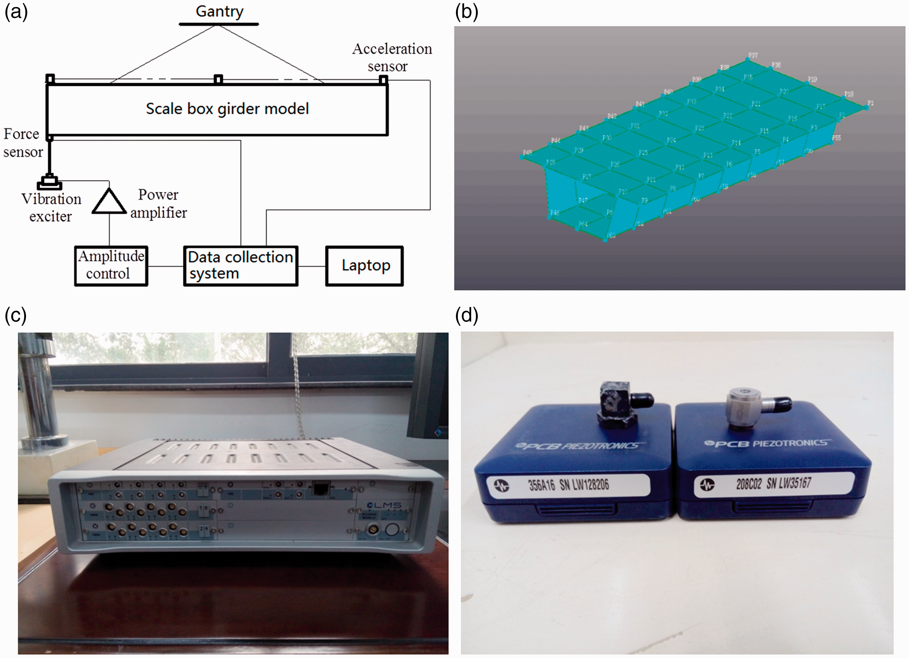
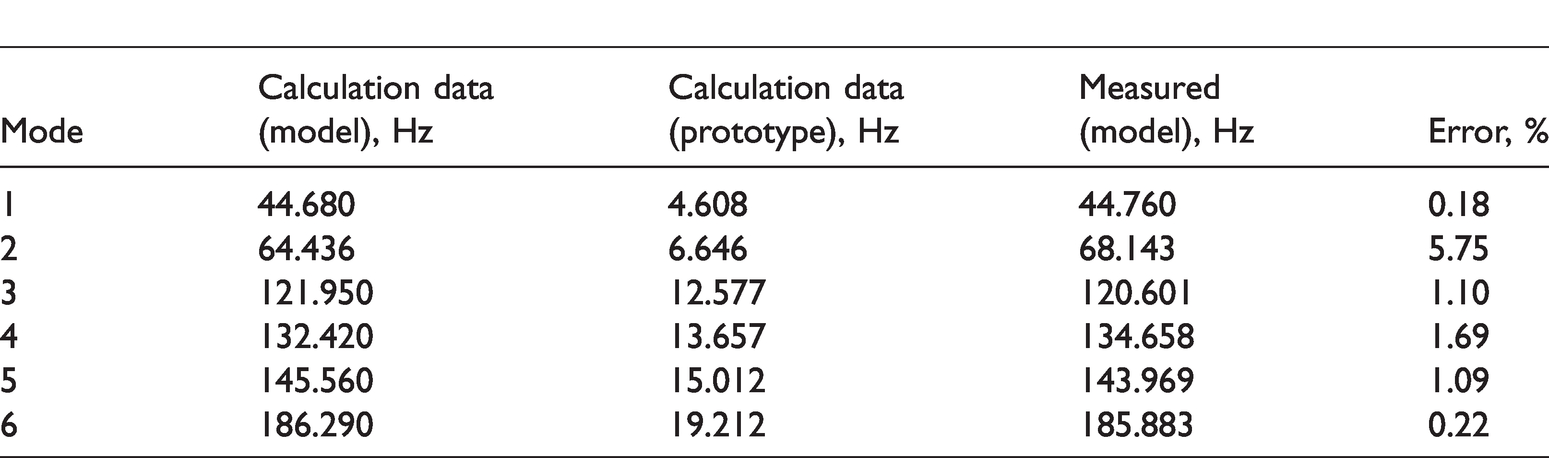
According to the analysis of the testing data, the first six order constraint modal frequencies are 44.76 Hz, 68.143 Hz, 120.601 Hz, 134.658 Hz, 143.969 Hz and 185.883 Hz, respectively. The vibration modes corresponding to the first six orders are shown in Figure 3(b).
Vibration modes of the theoretical and measured results: (a) the finite element calculation results and (b) the measured results.
The finite element computational models are established to calculate the constraint modal frequency for the 1/10 scale model and the prototype box girder by consideration of different geometrical parameters and material properties of the 1/10 scale model and the prototype. The calculated results are compared with the actual tested data, as shown in Table 2. The first three order constraint modal frequencies and corresponding vibration modes based on the testing and finite element calculation are presented in Figure 3. According to comparison and analysis of the results: (1) the error between the testing results and the calculation results for the constraint modal of the 1/10 scale model is within 5.75%, and the vibration mode remains the same at different orders, which means that the testing results and the finite calculation model are correct as long as the parameters of the 1/10 scale model are correct. (2) The constraint modal of the 1/10 scale model and the prototype box girder satisfy the similarity relation of
Comparison of theoretical and measured modal frequencies.
Test analysis on vibration- and noise-reduction in a damping plate
Box beam webs are middle plates with large surface areas that can be connected with the top plate, flange plate and bottom plate; these can cause fairly significant structural vibrations and low-frequency noise in the box girder under dynamic train loads and are therefore selected in this paper for the detailed study.
Introduction to the vibration and noise tests
Damping material
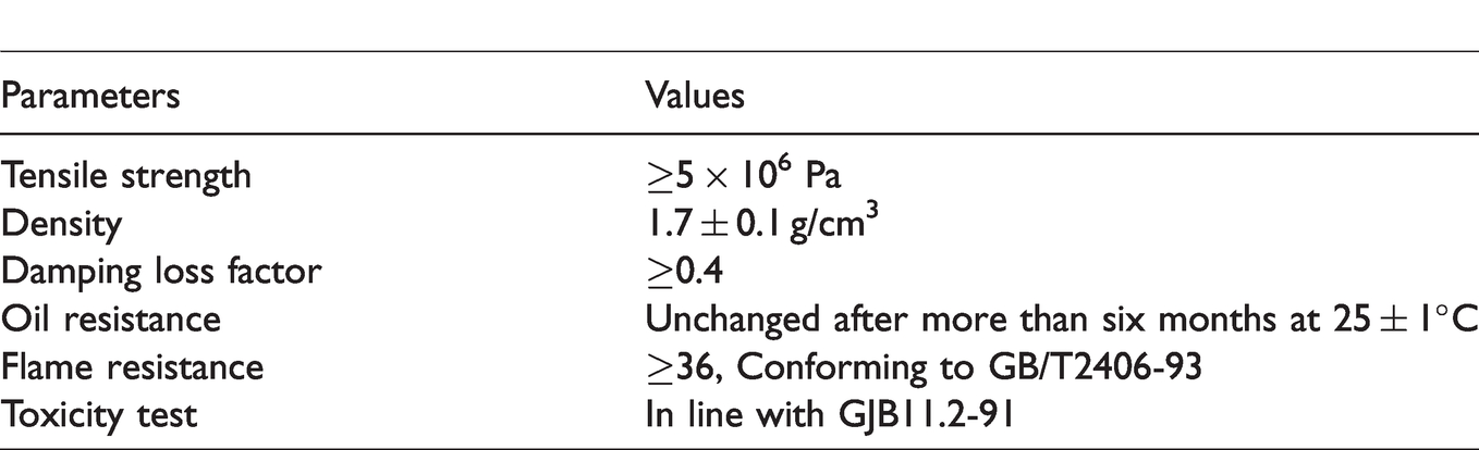
A TD09 high-performance damping plate made of black flat bulk material containing damping glue, damping filler, a cross-linking agent and fire retardant substances. This material shows excellent resistance to fire and ageing, and is comparatively simple to construct. It can be used to restrain structural vibrations and noise, and is suitable for the installation of base materials with flat surfaces, such as the box girder. Table 3 shows the parameters for the TD09 damping material.
Parameters of the TD09 damping material.
Test method
One of the web sides was selected, and the surface fully covered with the damping plate. A contrast analysis on the vibration and noise reduction of the damping plate through hammer and vibration excitation was then carried out. During the test, the excitation point was set at the middle of the top plate of the mid-span section. All six vibration measuring points were set at the mid-span section and located on both sides of the flange plate, at the two web side centres and at the sides of the two bottom plates near the corners. The noise points were set at the mid-span section of the box girder model. The two sides of the webs, Point D and Point D', were 10 cm away from the box girder (see Figure 4). The test was performed in a semi-anechoic chamber at a temperature of 25°C.
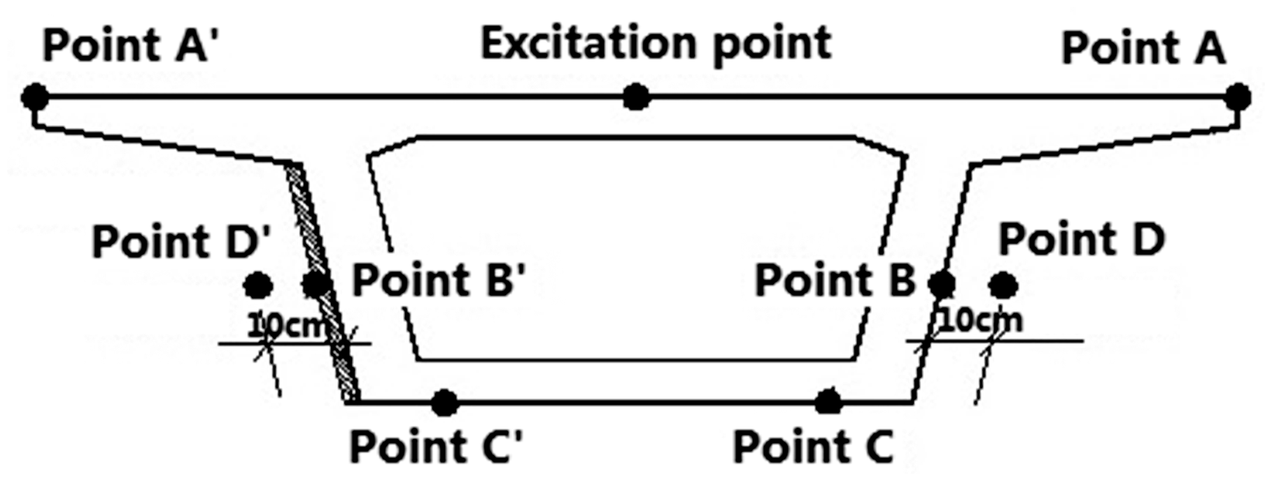
Measuring points.
Vibration test results and analysis
In order to reflect the vibration reduction effect of the damping plate on the prototype box girder more directly, on the basis of the test results and the similarity ratio of the frequency, the test results were inverse calculated to the box girder prototype (see Figure 5). Figure 5 shows the vibration acceleration level and acceleration admittance curves for Points B and B'. Figure 6 shows the acceleration admittance curves for Points A and A' of the flange plate and for Points C and C' of the bottom plate, respectively.
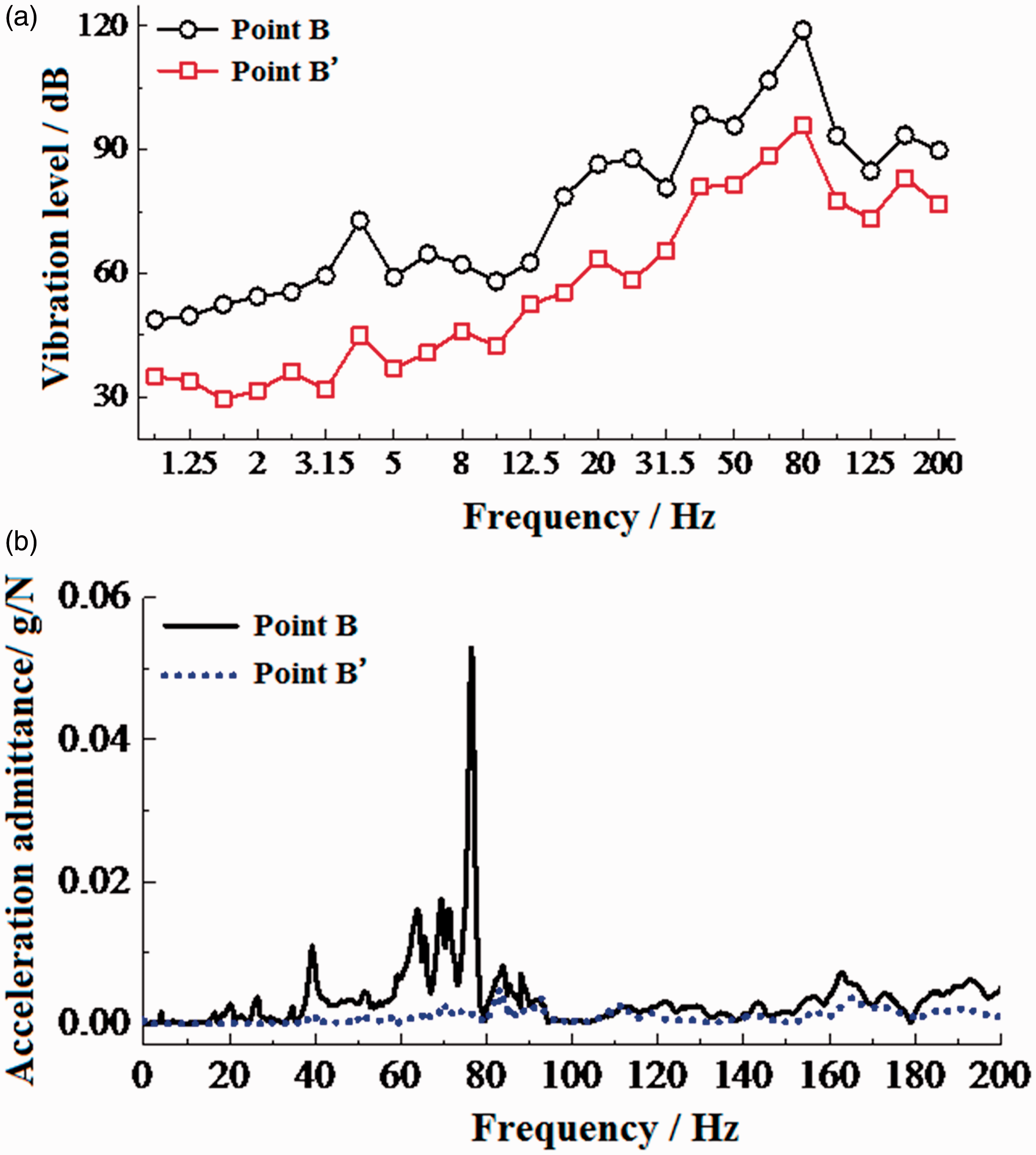
Contrast analysis on the vibration responses measured at B and B': (a) frequency-domain vibration levels and (b) acceleration admittance curves.
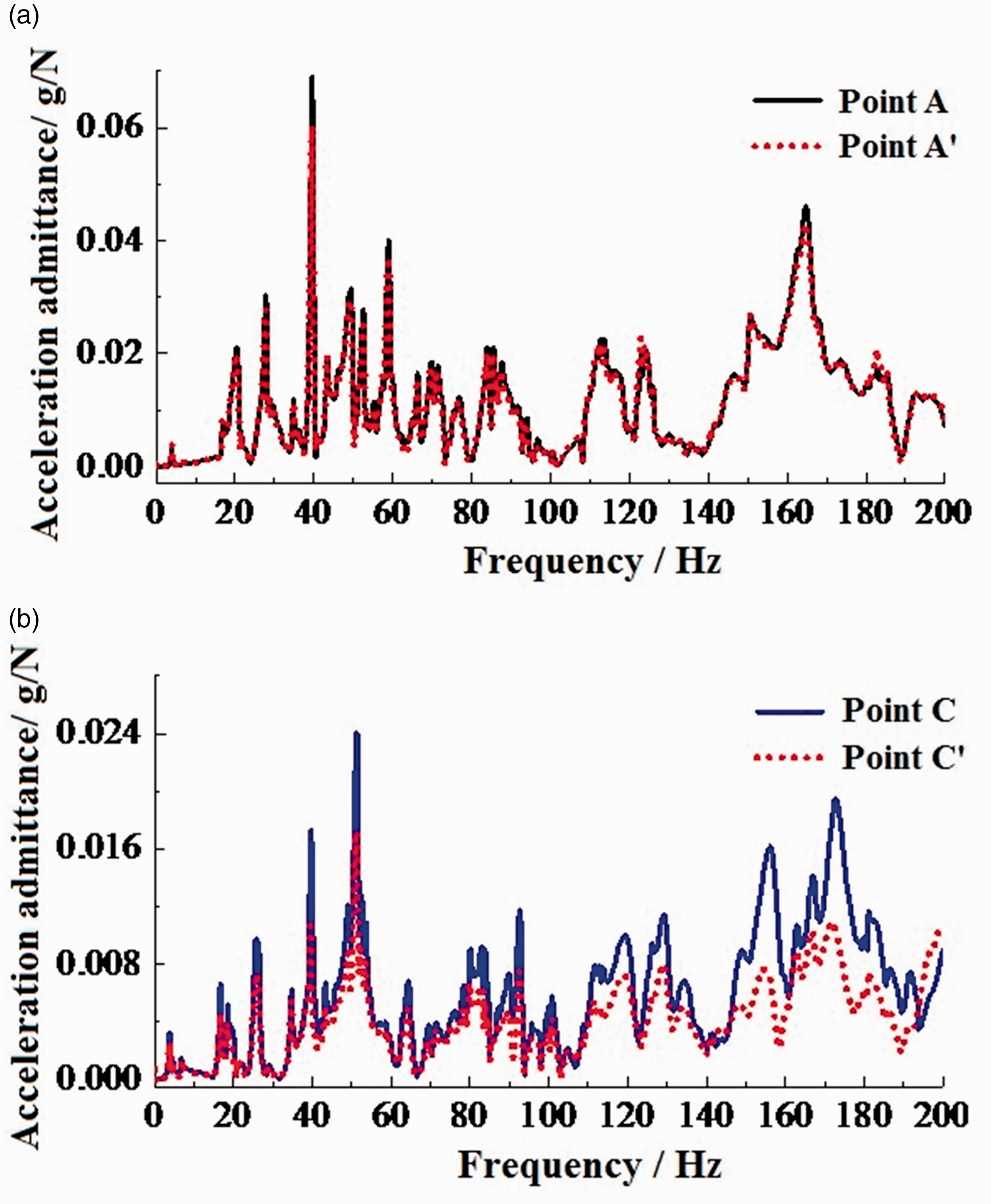
Acceleration admittance curves: (a) Point A and A' and (b) Points C and C'.
As can be seen in Figure 5:
The damping plate is obviously effective in reducing the web vibrations at different frequencies. The difference between the vibration acceleration levels at the laid/unlaid sides was kept within 10.2–29.5 dB; The box girder web vibrations remained mostly within the 20–100 Hz range, and reached a peak in the (70.8–89.1 Hz) frequency band with a centre frequency of 80Hz, indicating that the web was subject to a dense local vibration mode within this frequency band; As shown in Figure 5(b), the vibration reduction effect of the damping plate was very pronounced, and clearly helpful in restraining the local web vibrations caused by the box girder mode.
As shown in Figure 6: (1) the acceleration admittance curves of the flange plate parts at both ends of the mid-span section nearly coincided with each other, except for a few frequencies where slight differences were detected. This would indicate that the web with the damping plate had little influence on the vibration reduction of the flange plate. (2) The acceleration admittance curve of Measuring Point C' at the bottom plate was similar to that of Measuring Point C, except in certain frequency ranges (f = 190 Hz–200 Hz). All the acceleration admittance amplitudes of Measuring Point C' were lower than those of Measuring Point C, indicating that the web with the damping plate could reduce the vibrations at the bottom plate on the same side to a certain extent. The main reason for this was that the webs were middle plates connected to the top and bottom plates, and the vibrations transferred to the box girder webs at different frequency ranges had thus been reduced because of the damping plate.
Noise test results and analysis
The excitation was performed using a vibration exciter. The test consisted of five groups and each part lasted 60 s. See Figure 7 for the test pictures and Figure 8 for the measured results.
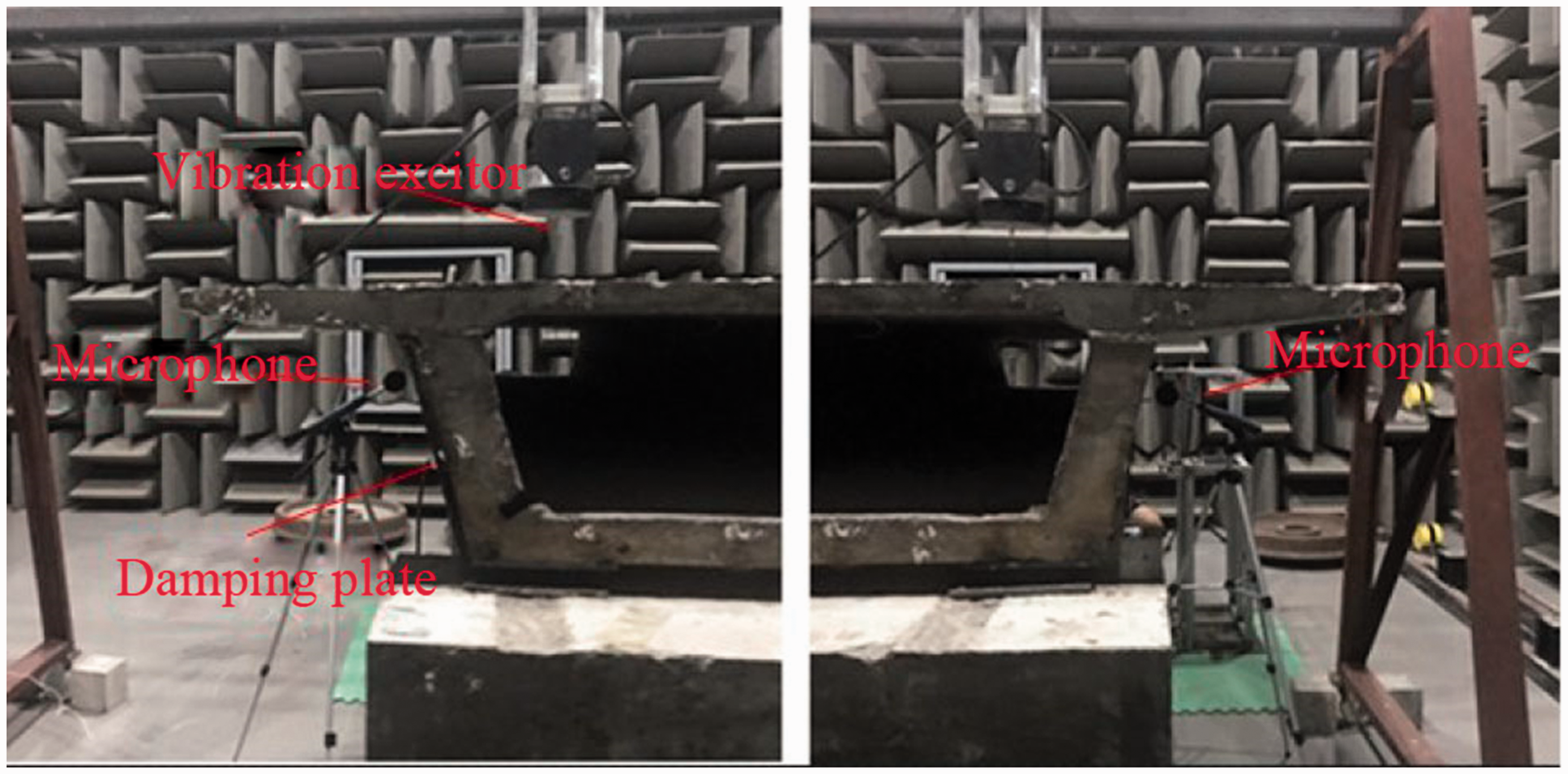
Acoustic test pictures.
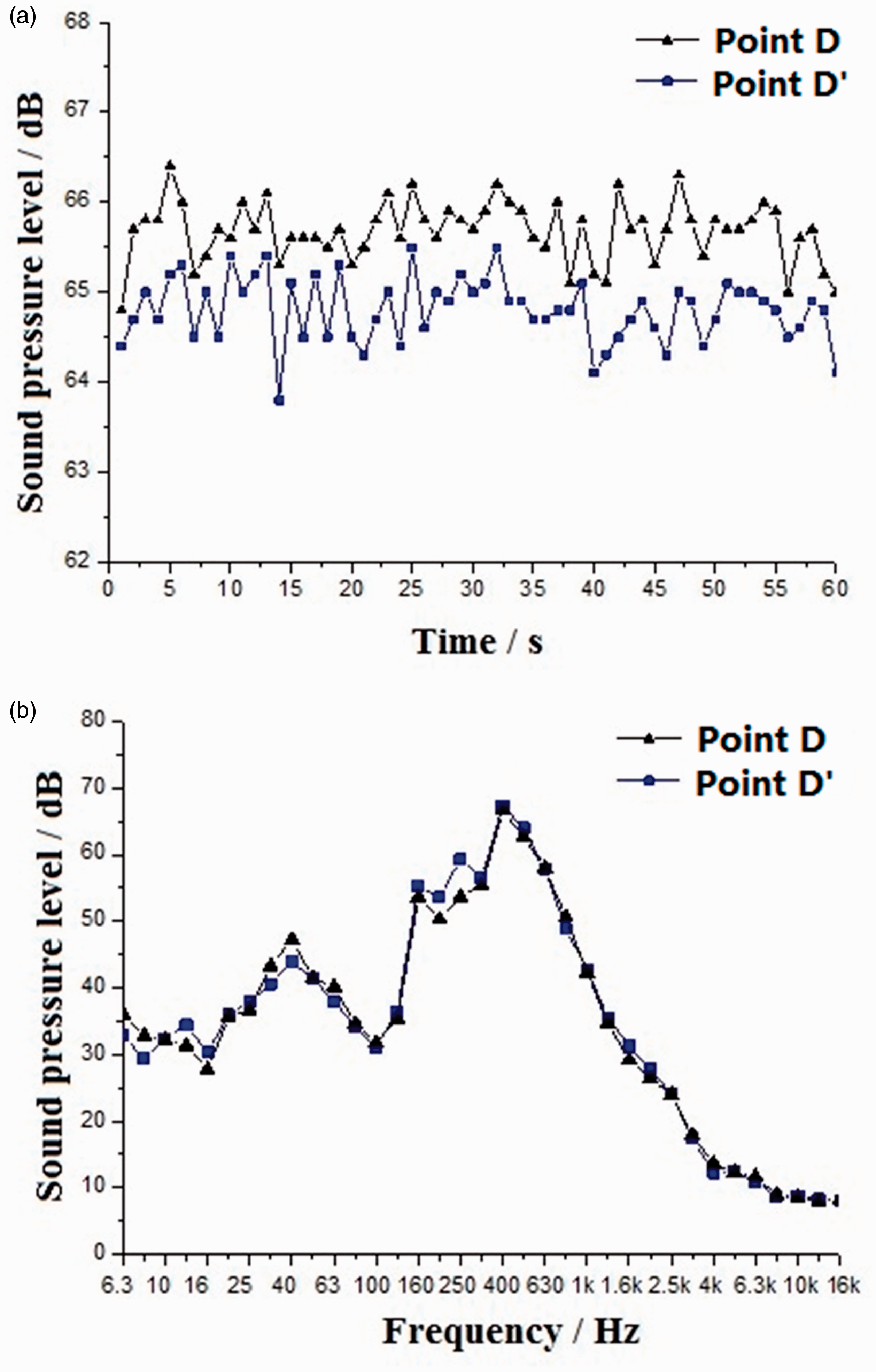
Comparison of measured sound pressure levels: (a) time–history sound pressure levels and (b) 1/3 OCT sound pressure levels.
As shown in Figure 8: (1) the damping plate was helpful in slightly reducing the structural noise of the box girder, with an amplitude of about 1 dB(A). The equivalent sound levels of Points D and D' calculated using the time–history curves of the sound pressure levels were 65.69 dB(A) and 64.28 dB(A), respectively, a difference of 1.41 dB(A); (2) the peak noise value was kept within the 25–1000 Hz range, and the damping plate was helpful in reducing noise at almost all frequencies. The noise reduction effect was best at 250 Hz, getting up to around 4 dB(A).
Influence of damping plate on sound contribution of box girder panel
For the structural noise of a railway box girder, acoustic sensors are often used in field tests. In this paper, the test results on Point D and Point D' included not only the radiated noise of the web but also the noise contribution from other panels such as the flange plate and bottom plate. The acoustic array commonly used in acoustic positioning tests was deemed unsuitable for identifying LF structural noise, and the noise contribution of all concrete panels is difficult to obtain through testing. Therefore, the finite-boundary element methods were used in order to analyse the influence of the damping plate on the sound contributions of the box girder panels.
Numerical calculation method of panel contribution
A finite element model was established based on the geometric parameters of the 1/10 scale box girder model. The vibration response of the box girder was then calculated with a harmonic load applied at the centre of the top plate of the finite element model, and the vibration response was adopted as the sound boundary condition in the numerical calculation. After this, the sound contribution of both sides of webs is calculated by using the boundary element method based on the theory of sound contribution analysis of panels.
For the acoustic test of the 1/10 scale box girder model, the analysis points were chosen at both sides of the mid-span section of the box girder, namely Point D and Point D'. The positions of Points D and D' were 10 cm away from the box girder (see Figure 4), and the corresponding web at the damping side was Panel 1 and that at the other side was Panel 2.
Comparison of sound power contribution
Figure 9 shows the calculated radiated sound power of the box girder. It can be seen from Figure 9 that there are two peaks of radiated sound power level at 17 Hz and 251 Hz, which are analysed as follows.
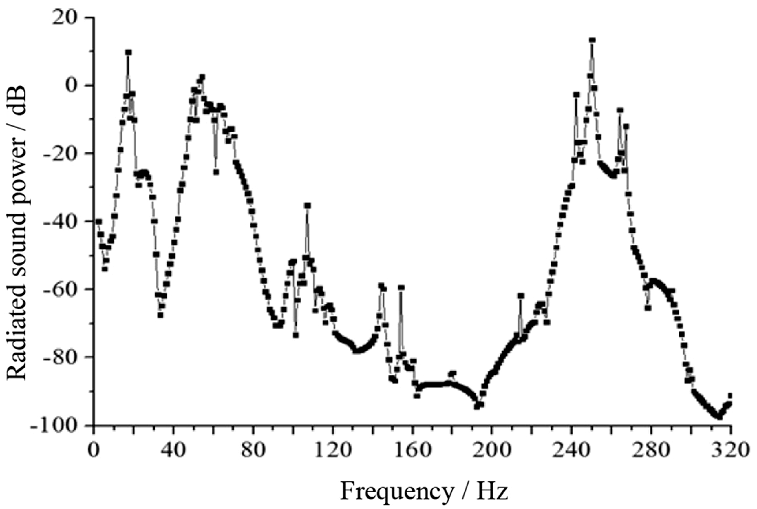
Curve for sound power level.
The analysis on sound power contributions can help to understand the contribution of radiated noise from each box girder panel to environmental noise. Figure 10 shows the sound power contributions of these two webs corresponding to the webs at the two sides of the box girder at 17 Hz and 251 Hz.
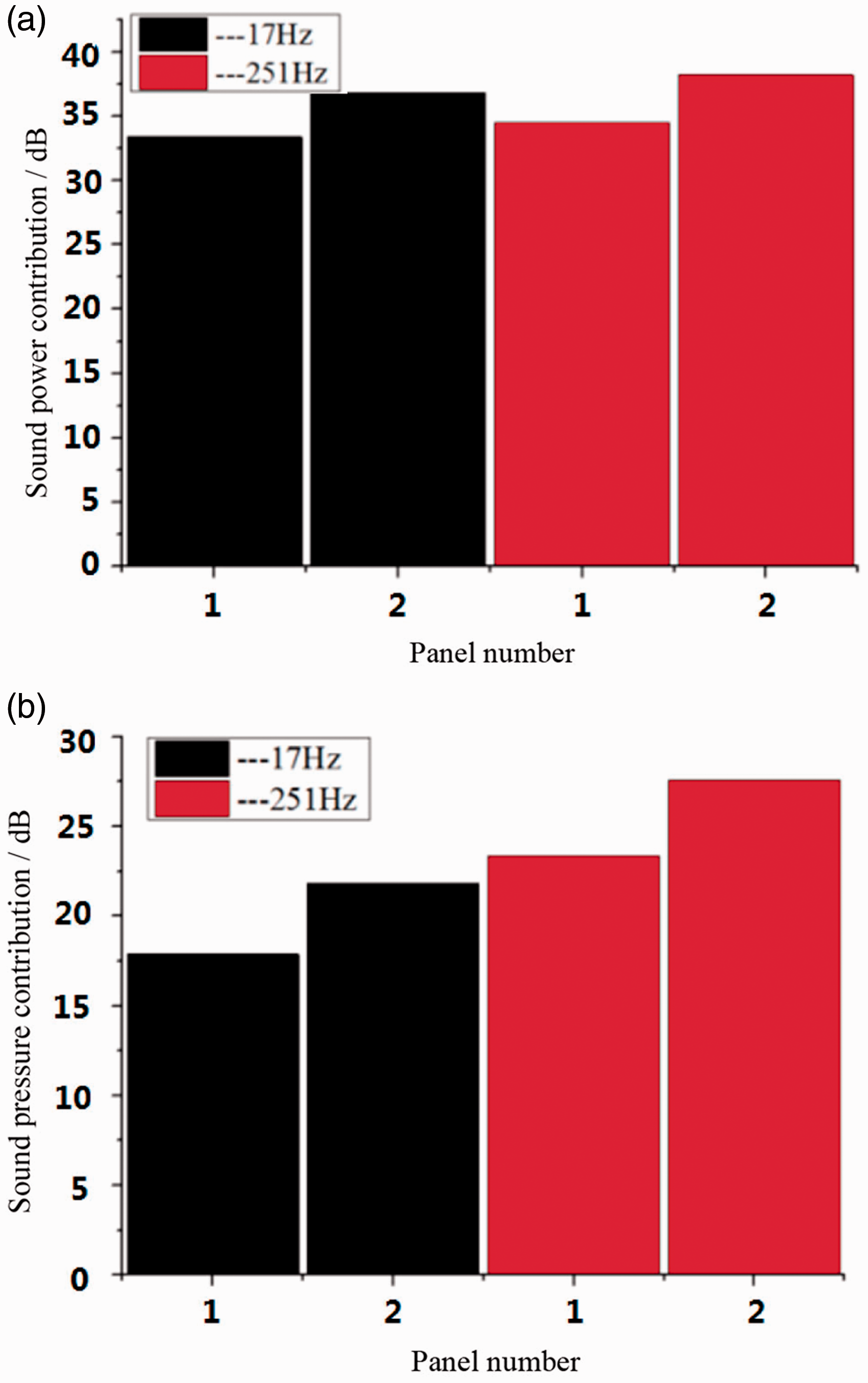
Comparison of panel contributions: (a) sound power contribution and (b) sound pressure contribution.
According to Figure 10(a), at peak frequency, the sound power contribution at the side where a damping plate had been fitted was significantly lower than that at the side with no damping plate. At 17 Hz, the sound power contribution of Panel 1 was 33.4 dB, 3.4 dB less than that of Panel 2 (36.8 dB); At 251 Hz, the sound power contribution of Panel 1 was 34.5 dB, 3.7 dB less than that of Panel 2 (38.2 dB).
Comparison of sound pressure contribution
In order to make a further contrast analysis on the influence of damping on sound pressure contribution, a comparison between the sound pressure contribution of Panel 1 to Point D' and that of Panel 2 to Point D at a peak frequency was carried out; see Figure 10(b) for the result.
According to Figure 10(b), the sound pressure contribution from the panel at the side where a damping plate was fitted was significantly lower than that at the side with no damping plate. At a frequency of 17 Hz, the sound pressure contribution of Panel 1 to Point D' was 17.9 dB, while the sound pressure contribution of Panel 2 to Point D was 22.8 dB, a decrease of 4.9 dB. At a frequency of 251 Hz, the sound pressure contribution of Panel 1 to Point D' was 23.3 dB, while the sound pressure contribution of Panel 2 to Point D was 27.5 dB, a decrease of 4.2 dB.
Conclusions
A 1/10 scale box girder model test system was designed and constructed for this paper by taking the Beijing–Shanghai high-speed railway as a prototype. The influence of a damping plate on the vibrations and noise of the box girder was measured by means of a series of comparison tests, and the influence of the damping plate on sound power and pressure contributions at the corresponding point were analysed. To a certain extent, the results are useful for vibration and noise control in high-speed railways. The main conclusions are as follows:
Obvious vibration reduction effect of the damping plate on the concrete box girder. After the web was laid with a damping plate layer, the vibration acceleration level would decrease by about 10.2–29.5 dB under the dynamic loads, and the vibrations of the bottom plate would also decrease at the same time; According to the sound pressure levels of the field spots corresponding to the two web sides of the box girder measured in a semi-anechoic chamber, the damping plate was helpful in reducing the structural noise of the box girder. The decrease in amplitude was about 1.0 dB, though the functional frequency was not the full frequency domain; noise could be decreased by about 4.0 dB at 250 Hz; At peak frequency, the sound power contribution of the panel on the side where a damping plate had been fitted was significantly lower than that on the side with no damping plate. When the frequencies were 17 Hz and 251 Hz, the sound power contributions on the side with the damping plate decreased by 3.4 dB and 3.7 dB, respectively, compared with the other side, while the sound pressure contributions of the panel decreased by 4.9 dB and 4.2 dB, respectively.
Footnotes
Declaration of conflicting interests
The author(s) declared no potential conflicts of interest with respect to the research, authorship, and/or publication of this article.
Funding
The author(s) disclosed receipt of the following financial support for the research, authorship, and/or publication of this article: The work was supported by the National Natural Science Foundation (51868023 & 51978264) and the Major Project of Ministry of Education of Jiangxi Province (GJJ170357).