
Abstract
Vibrations are usually caused by continuous disturbances with large amplitudes. Different from other control methods, disturbance rejection control is a potential method, which considers the unknown disturbances in the control design. To remedy the shortcomings of the existing disturbance rejection control in the vibration reduction of structures especially under high-frequency periodic disturbances, this paper aims to improve the control ability of the current disturbance rejection control for the vibration suppression of smart structures under any unknown periodic disturbances with high-order frequency or random disturbances varying fast. Afterwards, the refined disturbance rejection control is compared with the previously designed disturbance rejection control with proportional–integral observer and disturbance rejection control with generalized proportional–integral observer on both theoretical and numerical levels.
Introduction
Composite laminated thin-walled structures are widely used in aerospace and automotive engineering owing to their lightweight and relatively high stiffness. However, these kinds of structures have very high sensitivity for vibrations and very low damping ratios. In order to improve the structural performance, composite structures are proposed to be integrated with piezoelectric materials forming smart structures. Because of the sensory and actuation properties, smart structures have great potential in the applications of vibration control, acoustic control, health monitoring, and energy harvesting.
In the area of vibration or acoustic control, the structural performance strongly depends on the control strategy. Therefore, a mathematical model of smart structures for control design is needed, in order to avoid high expenses for experiments. Among the linear modeling techniques for electro-mechanically coupled smart structures, there exist many approaches using solid elements1–3 or plate/shell elements based on various hypotheses, e.g. classical plate hypothesis,4–6 first-order shear deformation (FOSD) hypothesis,7–10 higher-order shear deformation hypothesis,11–13 and zigzag hypothesis.14–16 Additionally, for nonlinear modeling, many researchers developed geometrically nonlinear models, e.g. Mukherjee and Chaudhuri, 17 Lentzen et al., 18 Dash and Singh, 19 Zhang and Schmidt, 20 and Zhang et al. 21 among others, and a few developed electro-elastic materially nonlinear models.22,23
A good vibration suppression ability needs a proper and well-designed control strategy. Based on the mathematical model of smart structures, many control schemes have been applied and developed for vibration suppression. The most frequently used control strategies are e.g. negative velocity/displacement feedback control,7,13,24,25 Lyapunov feedback control,24,26,27 bang-bang control,28,29 and linear quadratic regulator (LQR)/ linear quadratic Gaussian (LQG) control.16,30,31 Furthermore, many other advanced control schemes were developed for smart structures, for example independent modal space control,32,33 model predictive control, 34 sliding mode control,35,36 and robust control.37–39 Furthermore, without using a mathematical model, some intelligent control methods can be applied, like neural network control40–44 and fuzzy logic-based control.45–47
All the control strategies mentioned above only took the displacement or velocity as the measured output, and fed them back to controllers. They did not take into account the disturbances in the control design, due to the difficulty or impossibility of the measurement for unknown disturbances. However, most of the vibrations or acoustics are caused by disturbances, which have relatively large amplitudes compared to noises. In order to provide an effective control for vibration reduction, disturbances might be estimated using an observer, and afterwards the estimated signals are fed back to the controller. Concerning observation systems, several papers developed various observers for the estimation of unknown disturbances or other variables, for example, Hou and Müller, 48 and Darouach et al.48,49 developed full- and reduced-order observers, Söffker et al., 50 Morales and Alvarez-Ramirez, 51 König and Mammar, 52 and Müller 53 developed proportional–integral (PI) observers, and Kalsi et al. 54 and Zhu 55 developed sliding-mode observers.
Based on the estimated signal, the disturbances can be compensated by a control scheme, here called disturbance rejection (DR) control. The very early development of DR control with PI observer (DR-PI) can be found in the literature.56,57 Later, the method was applied to various nonlinear problems by Müller 58 and Söffker and Müller.50,53 Due to limitations of PI observers, the DR-PI control can only estimate and compensate unknown disturbances, which have low frequency or vary slowly. To break through the weakness of PI observers, a generalized proportional–integral (GPI) observer was proposed and developed recently by Zhang et al.9,59 The corresponding DR control with GPI observer (DR-GPI) has excellent performance in estimation and compensation of periodic disturbances with both higher and lower order frequency, in case the frequency is roughly or exactly known. Additionally, the disturbance position and the impact factor should be known in both the DR-PI and DR-GPI control schemes.
The literature survey reveals that the existing DR control strategies have very excellent control ability in some aspect, but they are still weak in applications to structures under periodic disturbances with high frequency. This paper aims to improve the current DR control, such that the refined DR control possesses very good ability in the vibration suppression for smart structures under any unknown periodic disturbances with high frequency or random disturbances varying fast. After that, the refined DR control as well as the DR-PI and DR-GPI control are theoretically analyzed and numerically compared.
Dynamic model of smart structures
With regard to smart structures comprising plates or shells, a two-dimensional FE method can be applied based on the Reissner–Mindlin hypothesis. By using Hamilton’s principle, a linear dynamic FE model can be obtained as


Here,
For the convenience of control design, a state-space model should be derived based on the dynamic FE model. We assume the state variable
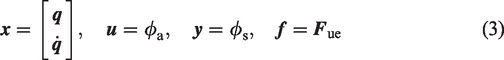
A state-space model can be constructed as


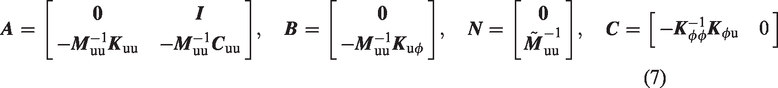
The state-space model in equations (4) to (6) has a disturbance input term
Conventional disturbance rejection control
Observation models
Disturbances applied to smart structures are usually unknown and can be of various types. Further assuming that the unknown disturbance vector is composed of a linear part and a residual error part, it leads to


Here,
Due to various types of disturbances, the components of the disturbance vector can be expressed by many forms of expressions, like Fourier series or high-order polynomial functions.
9
In the simulation part, periodic disturbances are mainly considered. Therefore, the components of the disturbance vector are assumed to be expressed by finite terms of Fourier series


The resulting coefficient matrices

While the coefficient matrices associated with equation (12) lead to the generalized proportional–integral (GPI) observer9,59
Closed-loop models
In the framework of DR control, the estimated disturbances are fed back to the controller like the estimated state variables. Therefore, the control law can be defined as

In the conventional DR control, the disturbance influence matrix
Generalized disturbance rejection control
Refined state-space model
In the conventional DR control, the disturbance influence matrix should be known. Moreover, for higher order frequency disturbances, DR-PI control fails, and DR-GPI control works well but it needs to know the disturbance frequency. To remedy the aforementioned shortcomings, firstly a refined state-space model is proposed, such that the closed-loop system does not contain the disturbance influence matrix
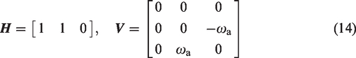
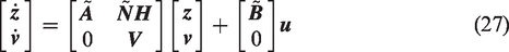
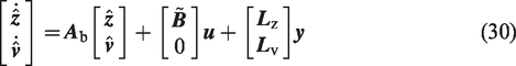
Based on the plant state space model given in equations (4) to (5), introducing a new state variable


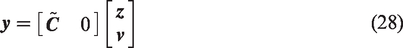
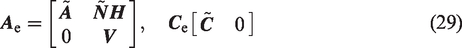
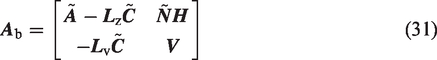
Here, the refined system matrix, control matrix, output matrix, and disturbance influence matrix are respectively

The new disturbance

From the matrix arrangement of

Here, the new disturbance includes the actual disturbance, as well as the plant state variables, which is defined as generalized disturbance. The resulting DR control based on the refined state-space model is called the generalized disturbance rejection (GDR) control.
Proportional–integral observer design
Following the design procedure of conventional PI observer, the generalized disturbance is assumed to be composed of a linear and a residual error part as

Neglecting the residual error and using step function to represent the generalized disturbance, the fictious model can be derived as


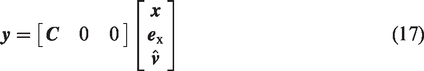
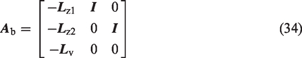
The extended model for the refined state-space model can be derived by introducing a new state variable comprised of
Here, the system matrix and the output matrix of the extended system are defined as
The extended observer system can be constructed as
Observer gain design
The observer gains must be well designed to stabilize the observation system. There are many ways to determine the observer gains
Riccati approach
The observer gains are assumed as


Here, b is a parameter for observer design, larger b produces larger observer gains.
Pole placement method
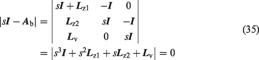
The aim of the observer design is to let the observation system stable, meaning that all the eigenvalues of
The eigenvalues can be derived by solving the following characteristic polynomial function of
Further assume that the observer gains,


Usually, smaller Toi leads to a more robust observer system.
Closed-loop control system
Due to the framework of disturbance rejection control, the control input is modified to

Here, the state variable is measurable and used directly, which is the typical difference compared with the conventional DR control. Usually the state variables are unknown in the conventional DR control, the estimated state variables are used in a feedback loop. The control gain for the dynamic part
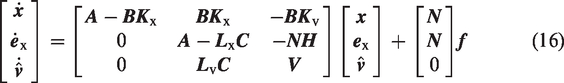
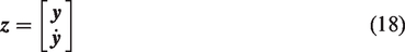
Assuming a new state variable for the closed-loop system as

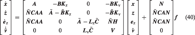
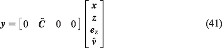
Additionally, the control input can be reconstructed as
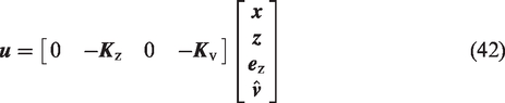
Here, the GDR control with PI observer is denoted as the GDR-PI control.
Active control simulation
Description of piezoelectric plate structure
A cantilevered composite plate structure bonded with two piezoelectric layers at the upper and lower surfaces, proposed by Lam et al.,
4
is shown in Figure 1. The host structure in the middle is made of T300/976 graphite–epoxy composite materials with four uniform thickness substrate layers sequenced as
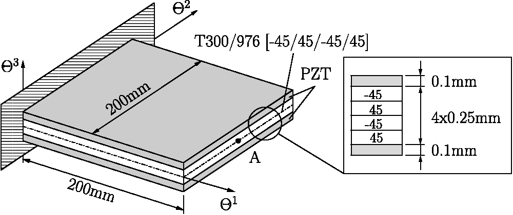
A cantilevered plate with piezoelectric layers.
Material properties of the smart plate.
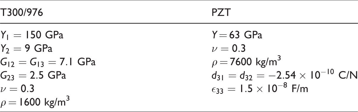
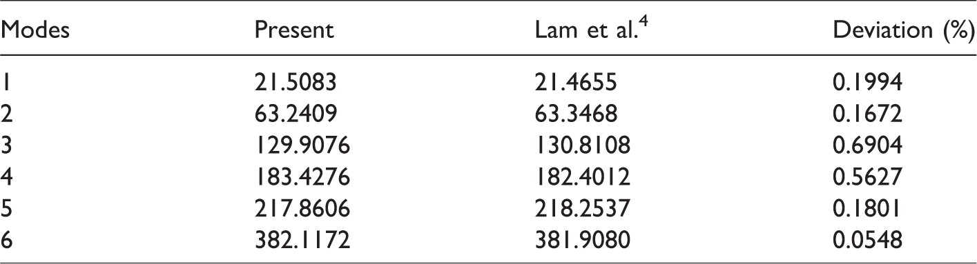
The upper layer of PZT is acting as a sensor, while the lower one is an actuator. An unknown disturbance is applied on tip point A. The dynamic FE model is derived by a discretization of 5 × 5 elements with uniformly reduced integration over the elements. Moreover, the damping matrix is assumed as Rayleigh damping coefficient with the ratio of 0.8% for the first six modes. For validation test, the first six eigenfrequencies are calculated, as shown in Table 2, and compared with those in literature, 4 which shows very excellent agreement.
First six eigenfrequencies of the plate.
Parameter configuration
In the control simulation, three control methods are implemented into vibration suppression of smart structures, namely LQR control, DR control with PI observer (DR-PI), DR control with GPI observer (DR-GPI), GDR control with PI observer (GDR-PI). The control parameters for the control strategies are listed in Table 3. From the parameter configuration in the table, it can be clearly recognized that the frequency of periodic disturbance should be known in DR-GPI control, which is not necessary for other controllers.
Parameters for various control strategies.
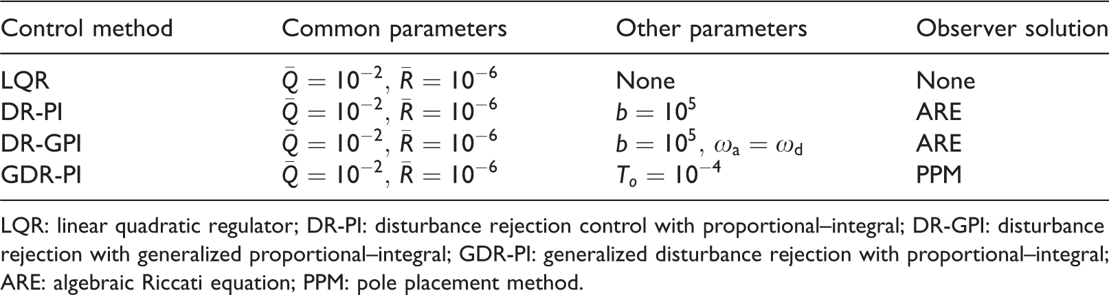
LQR: linear quadratic regulator; DR-PI: disturbance rejection control with proportional–integral; DR-GPI: disturbance rejection with generalized proportional–integral; GDR-PI: generalized disturbance rejection with proportional–integral; ARE: algebraic Riccati equation; PPM: pole placement method.
To analyze the performance of the GDR-PI control, various groups of parameters with changing
Parameters for study of the GDR-PI control.
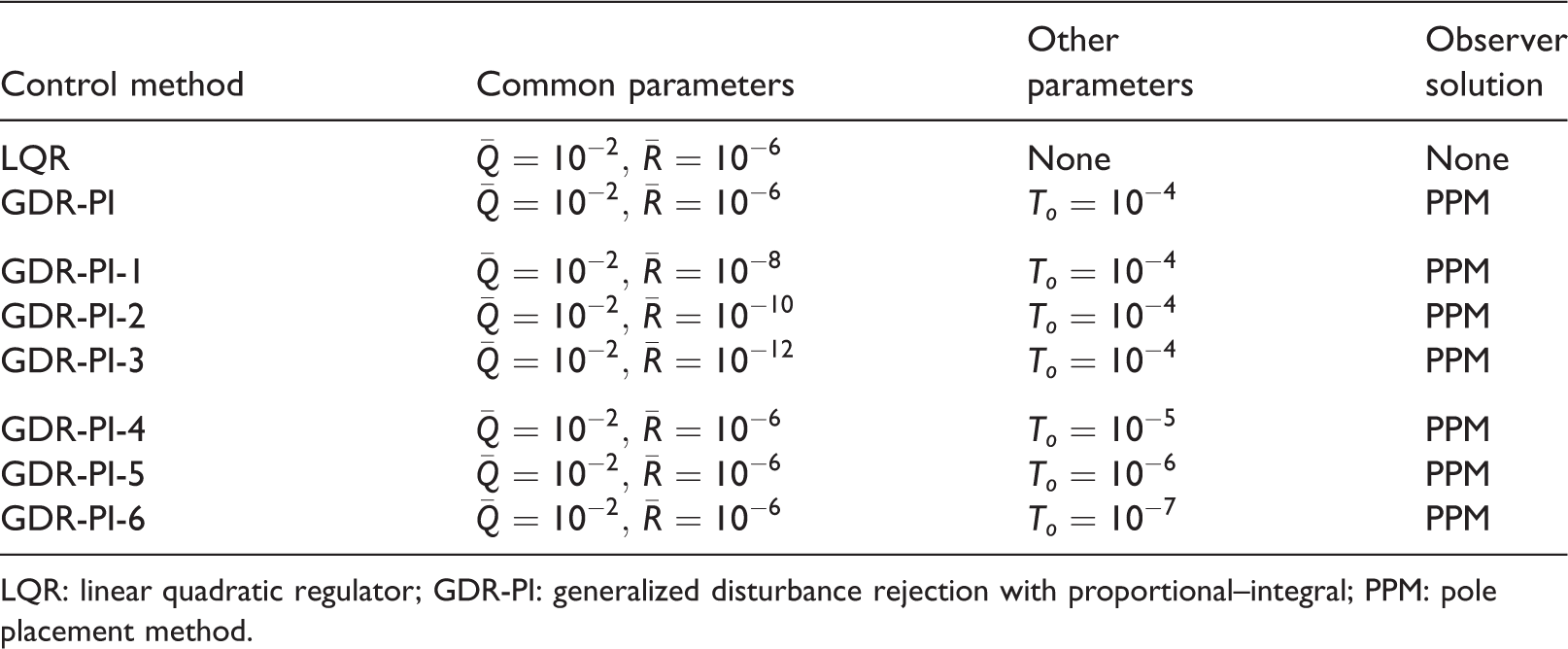
LQR: linear quadratic regulator; GDR-PI: generalized disturbance rejection with proportional–integral; PPM: pole placement method.
Amplitude–frequency response characteristics
Based on the parameters given in Table 3, the frequency response of the uncontrolled system, the closed-loop system of LQR, DR-PI, DR-GPI, and GDR-PI control can be presented by a Bode plot, as shown in Figure 2. The parameter table shows that the common parameters for all control schemes are the same, and the latter three schemes have additional parameters. As discussed in literature,9,59 the parameter b is used to stabilize the observer system, which has very slight influence on the frequency response if it is large enough. Note that the parameter To of GDR-PI significantly affects the frequency response. Generally, the smaller To, the better the characteristics of the frequency response.
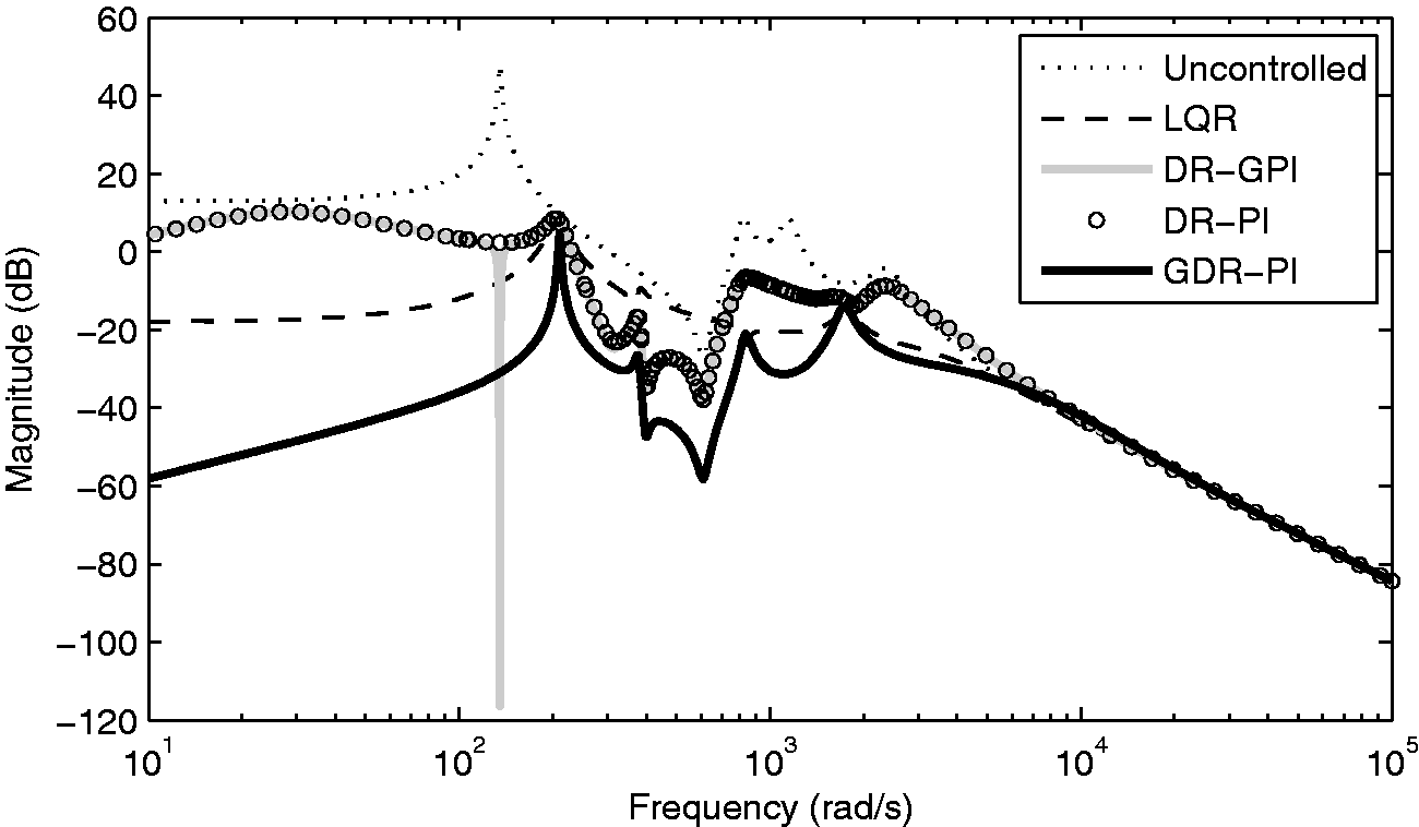
Bode plot of the smart plate.
From Figure 2, it can be seen that the controlled systems (LQR, DR-PI, DR-GPI, GDR-PI) have lower amplitudes than the uncontrolled system. Because LQR is an ideal control scheme, all state variables are fed back to the controller, which is not possible in a real system. In DR-PI and DR-GPI, the estimated state variables are used in the closed-loop system. That is the reason why LQR has smaller amplitudes than DR-PI and DR-GPI control, especially in the lower range of frequency. However, for DR-GPI control, since the frequency of disturbance is assumed to be known, it leads to significant lower amplitudes around the assumed frequency. In GDR-PI control, the mathematical model is absolutely different from conventional DR models. Therefore, it can reach extremely lower amplitudes by setting To or (
To deeply understand the GDR-PI control, several groups of parameters are considered in the following simulations. Decreasing each To by 10 times, the frequency–amplitude characteristics change greatly, as shown in Figure 3. The smaller To generates smaller amplitudes of vibrations. Alternatively, keeping To constant and decreasing each
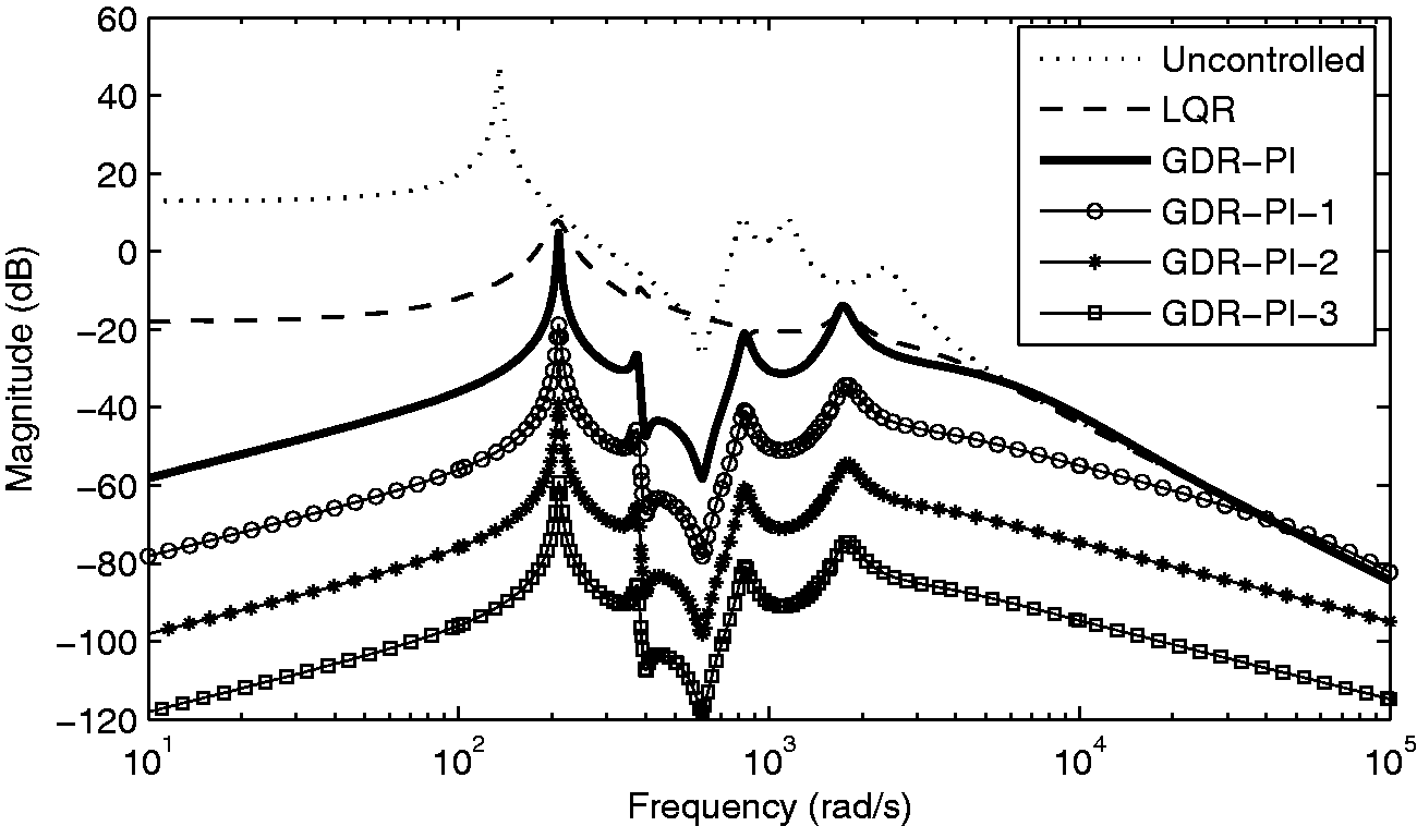
Frequency analysis of GDR-PI with changing To.
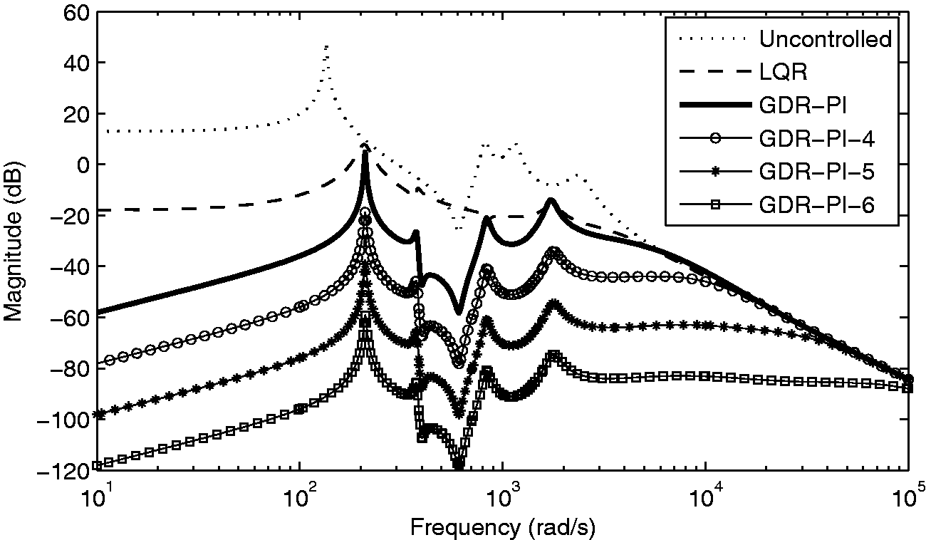
Frequency analysis of GDR-PI with changing
Time response analysis of vibration suppression
Considering a periodic disturbance waving at the first eigenfrequency of the structure,
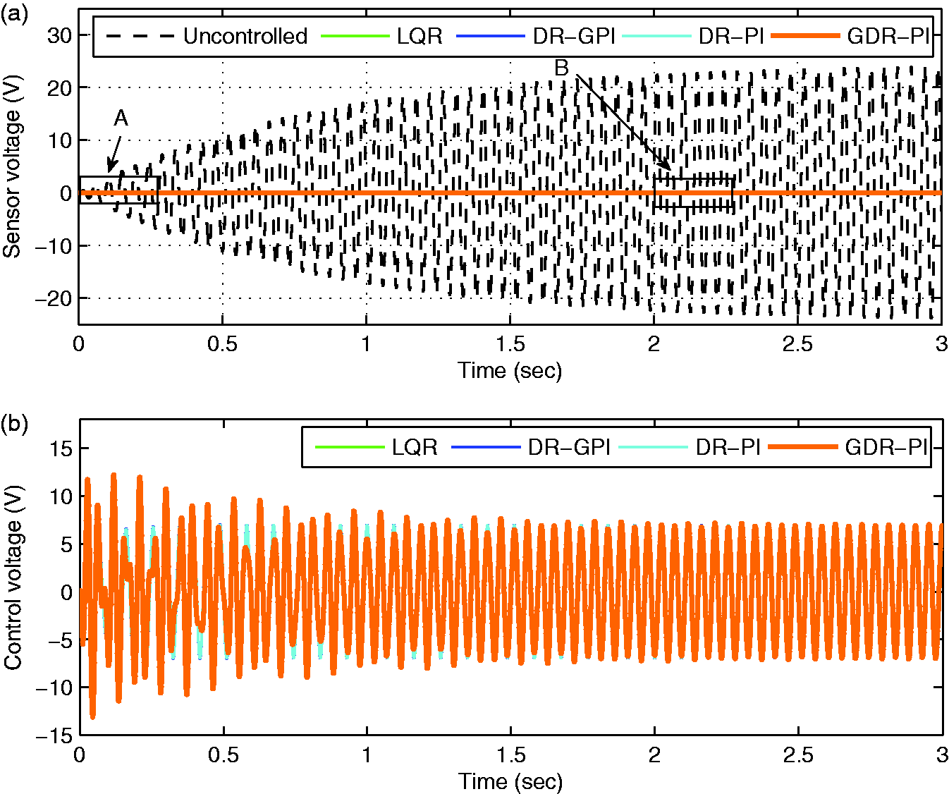
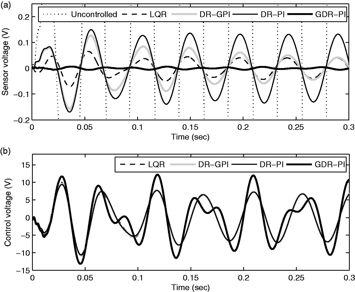
The dynamic behavior of the smart plate under a harmonic disturbance force with the frequency
The dynamic behavior of the smart plate under a harmonic disturbance force with the frequency
The dynamic behavior of the smart plate under a harmonic disturbance force with the frequency
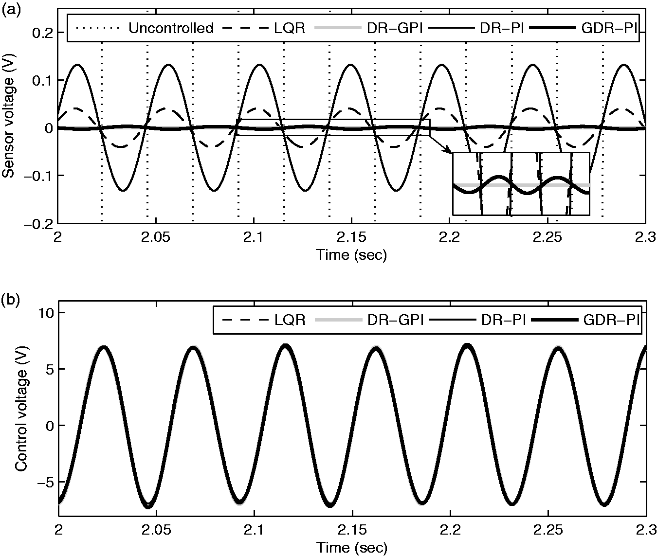
In the first stage, from 0 s to 0.3 s, it shows that GDR-PI performs best in vibration suppression in comparison with others. Due to the fact that the DR-PI control strategy fails to estimate the disturbance with relatively high frequency (first eigenfrequency), it leads to negative effect on vibration control, and only the free vibration is counteracted. Therefore, the DR-PI control cannot be better than the LQG control, and should be worse than the LQR control. Compared with the DR-PI control, a much better control result can be obtained by the DR-GPI control with increase of time. This is because the DR-GPI control can estimate the disturbance very precisely even with higher order frequency. However, the GPI observer needs rising time to follow the real disturbance. This is the reason that at the very beginning the result of DR-GPI is very close to that of DR-PI, and later the former one gets smaller amplitudes of vibration with increasing time. Going into the details of section B given in Figure 7, time from 2 s to 2.3 s, the results of DR-GPI shows excellent performance, since the GPI observer predicts the disturbance perfectly in the stable state.
Conclusions
Based on the conventional DR control, this paper has developed a GDR control with PI observer, for the vibration suppression of smart structures especially in the range of higher order frequency. In comparison to conventional DR control methods, DR-PI control and DR-GPI control, the current GDR-PI possesses very excellent performance.
From the simulation results, it can be seen that the parameters of (
Footnotes
Declaration of conflicting interests
The author(s) declared no potential conflicts of interest with respect to the research, authorship, and/or publication of this article.
Funding
The author(s) disclosed receipt of the following financial support for the research, authorship, and/or publication of this article: This work was partially supported by the National Natural Science Foundation of China (Grant No. 11972020 and 11602193), the Opening Fund of the State Key Laboratory of Mechanics and Control of Mechanical Structures, Nanjing University of Aeronautics and Astronautics, China (Grant No. MCMS-0517G01), the Nature Science Foundation of Shaanxi Province (Grant No. 2017JQ1027), and the Opening Fund of the State Key Laboratory of Structural Analysis for Industrial Equipment, Dalian University of Technology, China (Grant No. GZ1709).