
Abstract
This paper presents investigations into the development of an interval type-2 fuzzy logic control (IT2FLC) mechanism integrated with particle swarm optimization and spiral dynamic algorithm. The particle swarm optimization and spiral dynamic algorithm are used for enhanced performance of the IT2FLC by finding optimised values for input and output controller gains and parameter values of IT2FLC membership function as comparison purpose in order to identify better solution for the system. A new model of triple-link inverted pendulum on two-wheels system, developed within SimWise 4D software environment and integrated with Matlab/Simulink for control purpose. Several tests comprising system stabilization, disturbance rejection and convergence accuracy of the algorithms are carried out to demonstrate the robustness of the control approach. It is shown that the particle swarm optimization-based control mechanism performs better than the spiral dynamic algorithm-based control in terms of system stability, disturbance rejection and reduce noise. Moreover, the particle swarm optimization-based IT2FLC shows better performance in comparison to previous research. It is envisaged that this system and control algorithm can be very useful for the development of a mobile robot with extended functionality.
Introduction
Self-balancing inverted pendulum systems have attracted a lot of interest within the research community. Inverted pendulum is an under actuated system and able to achieve stability after facing a disturbance by obstacles or while moving on a sloped path. The main control challenges are to achieve fast settling time and low state steady error while in the upright position. Inverted pendulum systems vary from single link, double, and triple links.
Recent research in triple-link pendulum has considered pendulum on cart systems. For example, Sharma and Sahu 1 used Lagrange equation to model a triple-link inverted pendulum on cart system and linearized it to design a linear quadratic regulator (LQR) using single output. The system described in Wei et al. 2 used triple-link inverted pendulum on cart system and adaptive neural-fuzzy inference system (ANFIS) for its control. The proposed of this new system of triple links inverted pendulum on two-wheeled is due to the limitation of modelling and control of triple-link pendulum on two wheels system. Triple-link inverted pendulum on two-wheels system has become a significant research topic as it provides more complexity and flexibility in inverted pendulum study. Furthermore, this is a vital research area as there are several current and emerging applications, such as mobile robots, walking robots, and aircraft landing systems, that implement triple-link systems. Moreover, limited work is found on the use of IT2FLC for triple-link inverted pendulum systems, although IT2FLC has been shown as a powerful control technique for non-linear systems. 3
Over the past decades, FLC has been used in many applications for control with promising success. There are several works done on comparing type-1 fuzzy logic control (T1FLC) and IT2FLC and the results show that IT2FLC is far better than T1FLC. 4 IT2FLC has three-dimensional fuzzy membership function including upper boundary, lower boundary, and footprint of uncertainties which offer additional degree of freedom in order to deal with uncertainties that occur in membership functions. Moreover, IT2FLC has introduced one other element; type reduction before deciding the output from the controller. 5 However, designing a IT2FLC mechanism is complex because it has many parameters that need to be defined before it can work properly and there is no mathematical equation or specific method to determine the best parameter for the controller. Thus, optimisation techniques have been used for acquiring the best parameter values in terms of the shape of the membership function, fuzzy rule, rule base and building the fuzzy sets for the system to work properly. 6 Various optimization algorithms have been used to work with IT2FLC. These include spiral dynamic algorithm (SDA),7–9 genetic algorithm (GA),10–16 particle swarm optimization (PSO),17–21 artificial bee colony (ABC),22,23 ant colony optimization (ACO), 24 grey wolf optimizer (GWO)25,26 and hybrid optimization technique.27,28 The optimization algorithm is used to obtain the best parameters for IT2FLC. For example, hybrid genetic algorithm (HGA) has been used to optimize membership function of IT2FLC, building the fuzzy sets based on membership function, and identify the rule base. 13 The system described in Hamza et al. 19 is based on optimization using artificial bee colony to define a new defuzification method, and applied on the left and right points to obtain the best values inside IT2FLC. The grey wolf optimizer has also been used to tune the parameters of Takagi-Sugeno proportional-integral fuzzy controllers and this has been compared with PSO and GSA in a laboratory servo system. 25
SDA was introduced by Tamura and Yasuda in 2011. 42 SDA used logarithmic spiral as the model so that the diversification and search strategy can be fulfilled properly as the spiral movement always converges to the centre of the spiral. 7 SDA has successfully been embedded with fuzzy logic control as reported in Ghani et al., 8 where SDA is used to optimize the input and output scaling factors of a stair climbing wheelchair. The values obtained from SDA have improved the performance of stair climbing in terms of reducing the error of seat and increasing the user’s comfort.
PSO was introduced in 1995 by Kennedy and Eberhart. 41 PSO has a simple structure, and thus less computational time is needed. 29 There are several works done on IT2FLC optimization using PSO. The system described in Hassan 18 was the application of PSO to tune the input and output gains for a twin rotor multi input multi output system that used four IT2FLCs to control yaw and pitch axes with their cross coupling of the system. The result in Hassan 18 shows that the performance using PSO based IT2FLC was improved by 17.1%–33%. 17 discussed optimisation of parameters of primary membership function in IT2FLC using PSO and applied to a flexible-joint robot. The simulation results showed that IT2FLC with PSO was far superior in terms of robustness, accuracy, and interpretability.
The main focus of this paper is to design the robust controller to reduce vibration, cater uncertainties and disturbance rejection for a triple-link inverted pendulum on two-wheels system. The model is developed in Simwise 4 D environment for visualization and evaluation purpose. IT2FLC has been selected to control the system. As there are no specific methods or mathematical approach for obtaining the input and output gains of the system, conventional, trial and error method is commonly used. However, this consumes a lot of time for good performance to be achieved. Moreover, trial and error method is an unreliable method as there is no way to ensure that the values from the method are the best values for the system. Therefore, an optimization method using PSO and SDA is proposed in this work and the system performance is assessed in terms of stability and disturbance rejection.
The rest of the paper is organized as follows: The next section describes the modelling of triple-link inverted pendulum on two-wheels system. Then presents the stability control using IT2FLC. The SDA and PSO are described in the subsequent section, respectively. The results of this investigation are presented and discussed in the penultimate section, and the paper is concluded with conclusions.
Modelling of triple-link inverted pendulum on two-wheels system
Triple-link inverted pendulum on two-wheels system has been modelled in four dimensional design software SimWise 4D. This is to retain the complexity of the system and not rely on simplified mathematical modelling. Moreover, conventional mathematical modelling cannot satisfy human logic and is far from representing the model in the real world. Furthermore, SimWise 4D allows the user to build the model with various types of joint and motor, observe the movement of the model, and test the model with uncertainties and disturbances. SimWise 4D can further be integrated with Matlab/Simulink, allowing controller design and evaluation.
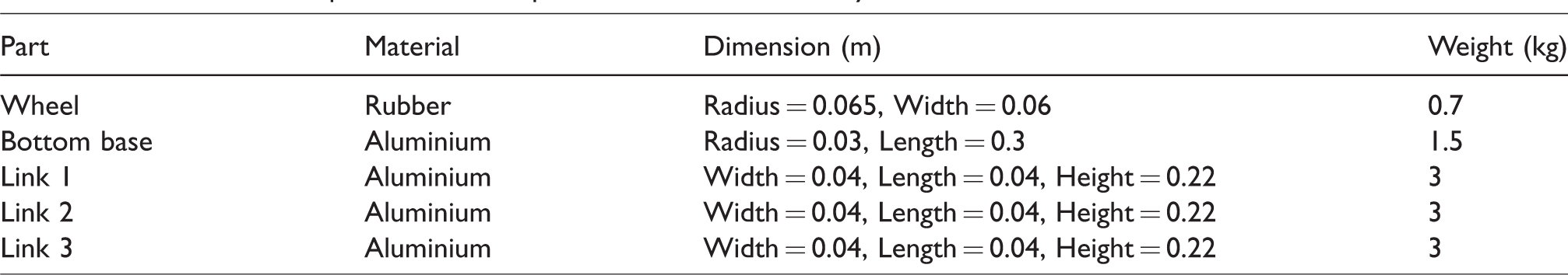
The triple-link inverted pendulum uses the same concept as other inverted pendulum on two-wheeled system. The first link is locked at the centre of the wheel, while the second and third links connected to the first link. Figure 1 shows a diagram of the model where rw is radius of the wheel, while mw, m1, m2, and m3 represent the masses of the wheel, link 1, link 2 and link 3, respectively. The lengths for these three links are represented by L1, L2, and L3. θ1, θ2, and θ3 are the tilt angles of the three links, respectively. The model is built as such so that for all three links to be controlled independently. The model of triple-link inverted pendulum on two-wheels system is built in SimWise 4D because it enables the user to determine the position of motor needed in the model and the input used in the system as shown in Figure 2. The system is modeled in an upright position. The right and left wheels are connected to the base using revolute motors to control the first link since the first link is locked at the base using a rigid joint. The second link is connected to the first link using a revolute motor and it is the same as the third link. The use of revolute motor is to enable the model to become more flexible since it is not in rigid position as the revolute motor can rotate around the y-axis. The parameters for the triple-link inverted pendulum on two-wheels system are based on previous research30–32 done on inverted pendulum on two-wheels systems, and these are shown in Table 1.
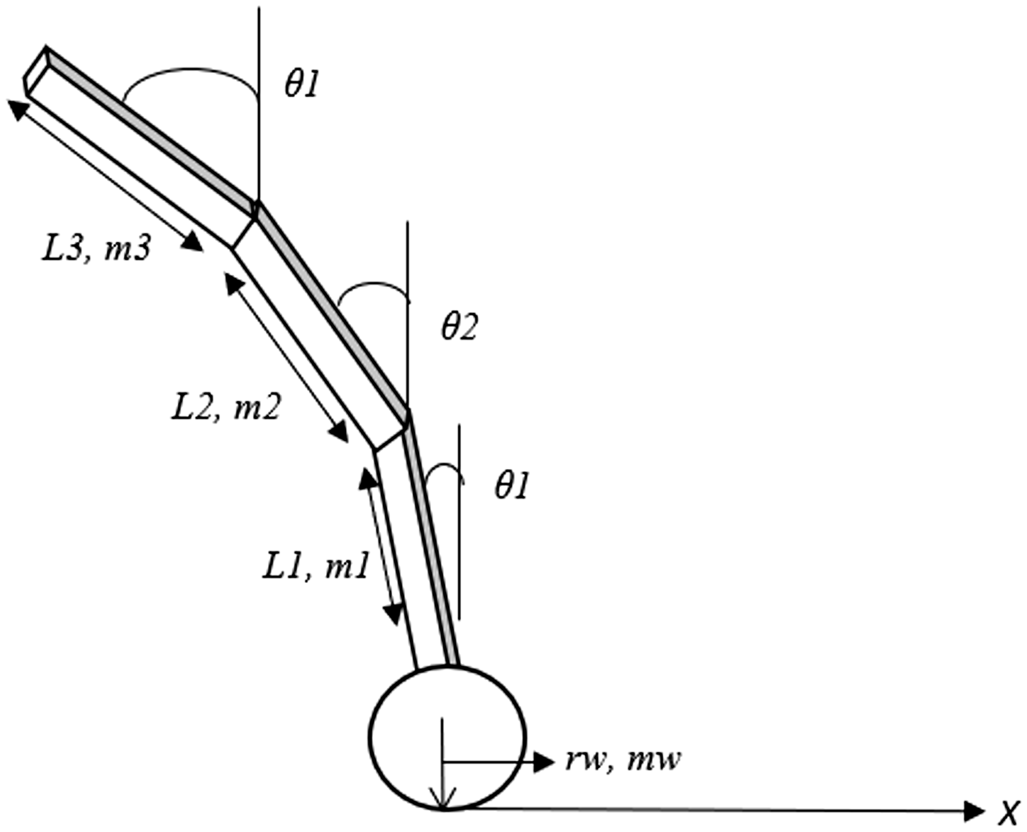
Schematic diagram of triple-link inverted pendulum on two-wheels system.
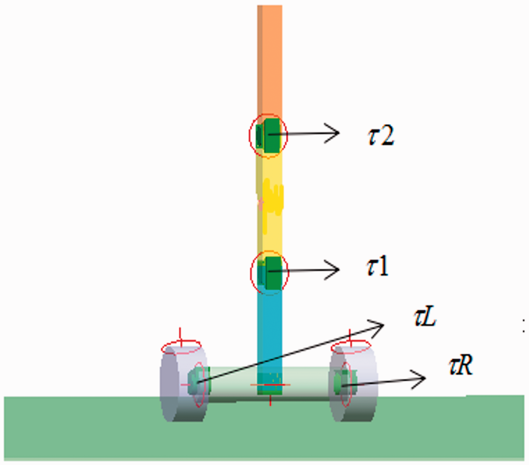
Model of triple-link inverted pendulum on two-wheels system in SimWise 4 D.
Parameters for triple-link inverted pendulum on two-wheels system.
Interval type-2 fuzzy logic control
Interval type-2 fuzzy logic control (IT2FLC) has been introduced by Zadeh 33 in 1975. IT2FLC consists of five elements, namely fuzzifier, a combination of rule base and database to form knowledge base, inference engine, type-reduction, and defuzzifier as shown in Figure 3. Membership function in IT2FLC is defined by type-2 fuzzy sets. The membership functions used in this work range from –1 to +1 using Gaussian membership function type, which is a better option for a flexible system like the inverted pendulum system. IT2FLC provides a three-dimensional membership function which consists of upper boundary, lower boundary, and footprint of uncertainty in order to give more precise output and eliminate uncertainties in the membership function. Figure 4 shows the membership function graph used in this work.33,34
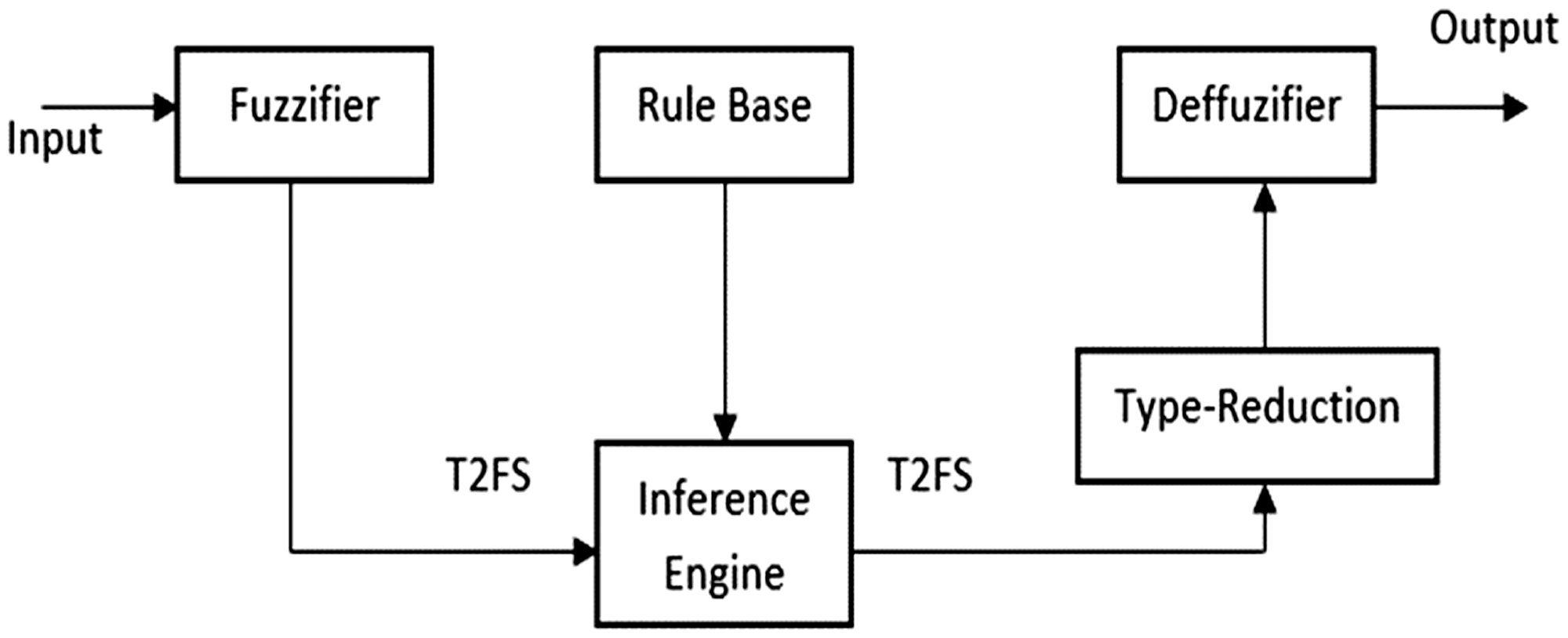
Block diagram of IT2FLC.
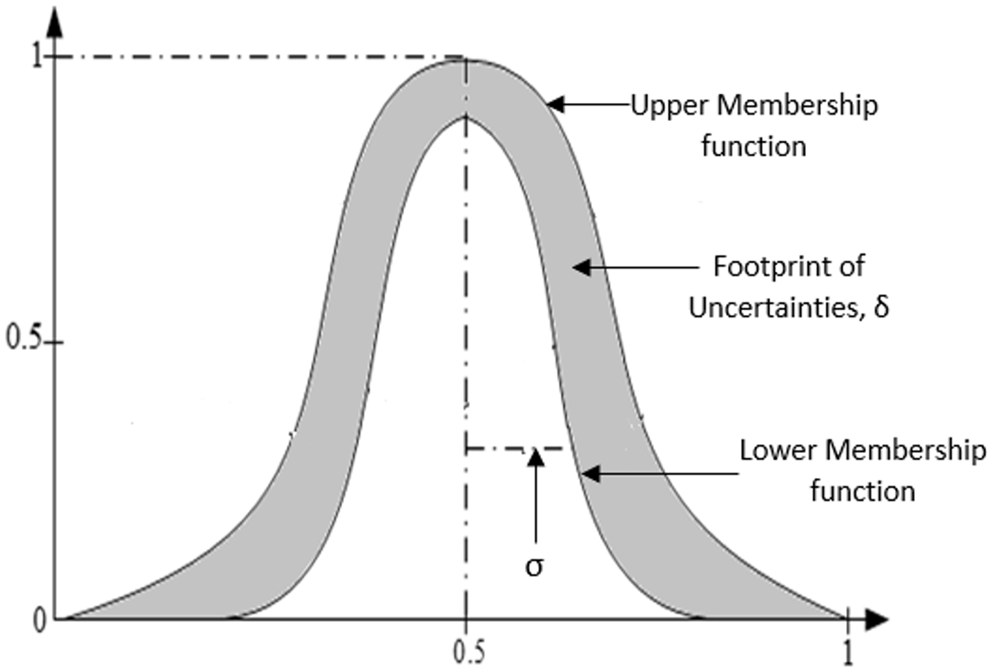
IT2FLC Gaussian membership function.
The process in IT2FLC starts with fuzzifier, which is used to fuzzify input crisp values of IT2FLC and converts into type-2 fuzzy sets. The interval type-2 fuzzy sets are defined as
35


The rule base is determined and defined so as to achieve the performance objectives of the work. Five linguistic variables are defined as negative big (NB), negative small (NS), zero (Z), positive small (PS), and positive big (PB) for IT2FLC inputs and outputs resulting in 25 rules as shown in Table 2. The fuzzy rules are formed as:
Rule base for IT2FLC.
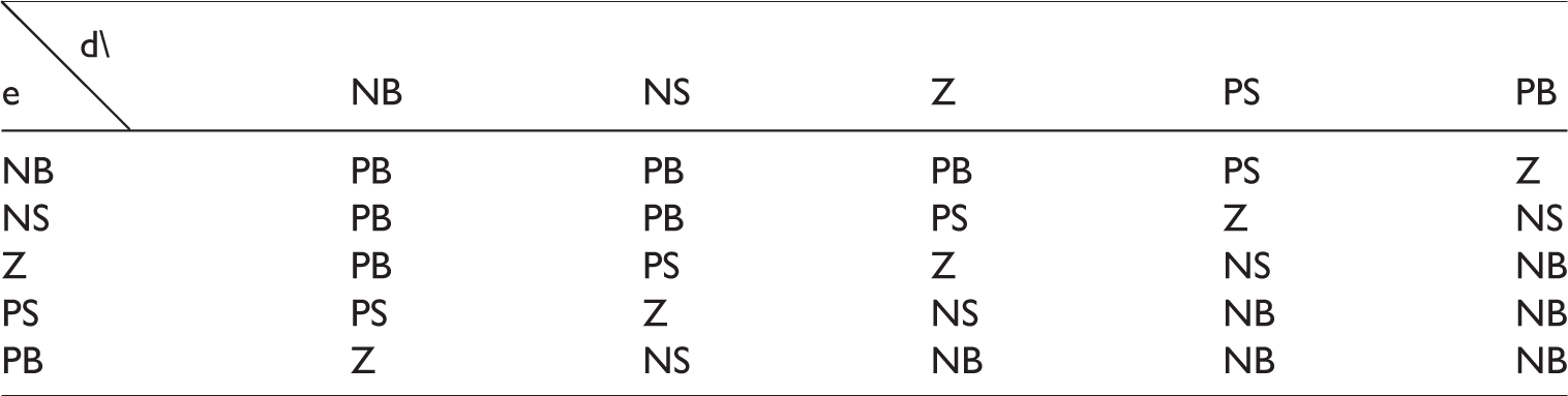
If x is A and y is B then z is Cwhere A and B are the two inputs of the IT2FLC and C is the output which will be used for stabilizing control.
The five membership functions used have their specific properties for each input. Firstly, they are centred at –1, –0.5, 0, 05, and 1. Second, they have the specific uncertain means, δ and standard deviation, σ in order to determine the size of membership function. The standard value for uncertain mean is 0.125, while for standard deviation is 0.418. These values are optimized in this work to find the optimal shape of the membership function for the system to work efficiently.
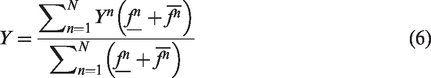
Before producing the IT2FLC outputs, type reduction method is performed to get the crisp output values. Nie-Tan type reduction is chosen in this work because it has been proven to be better compared to normal Karnik Mendel type reduction.
36
This is because it can produce outputs with better precision and faster due to the use of average value in membership function as
36
The stabilizing control is designed in Simulink/Matlab as shown in Figure 5. Figure 5 is the Simulink block diagram showing the usage of input output gains and switch to produce torque for the system. This system requires four loops to produce four values of torque in order to stabilize all three links. The error and change of error are obtained and used as inputs of the IT2FLC and the output produced is used to control the system.
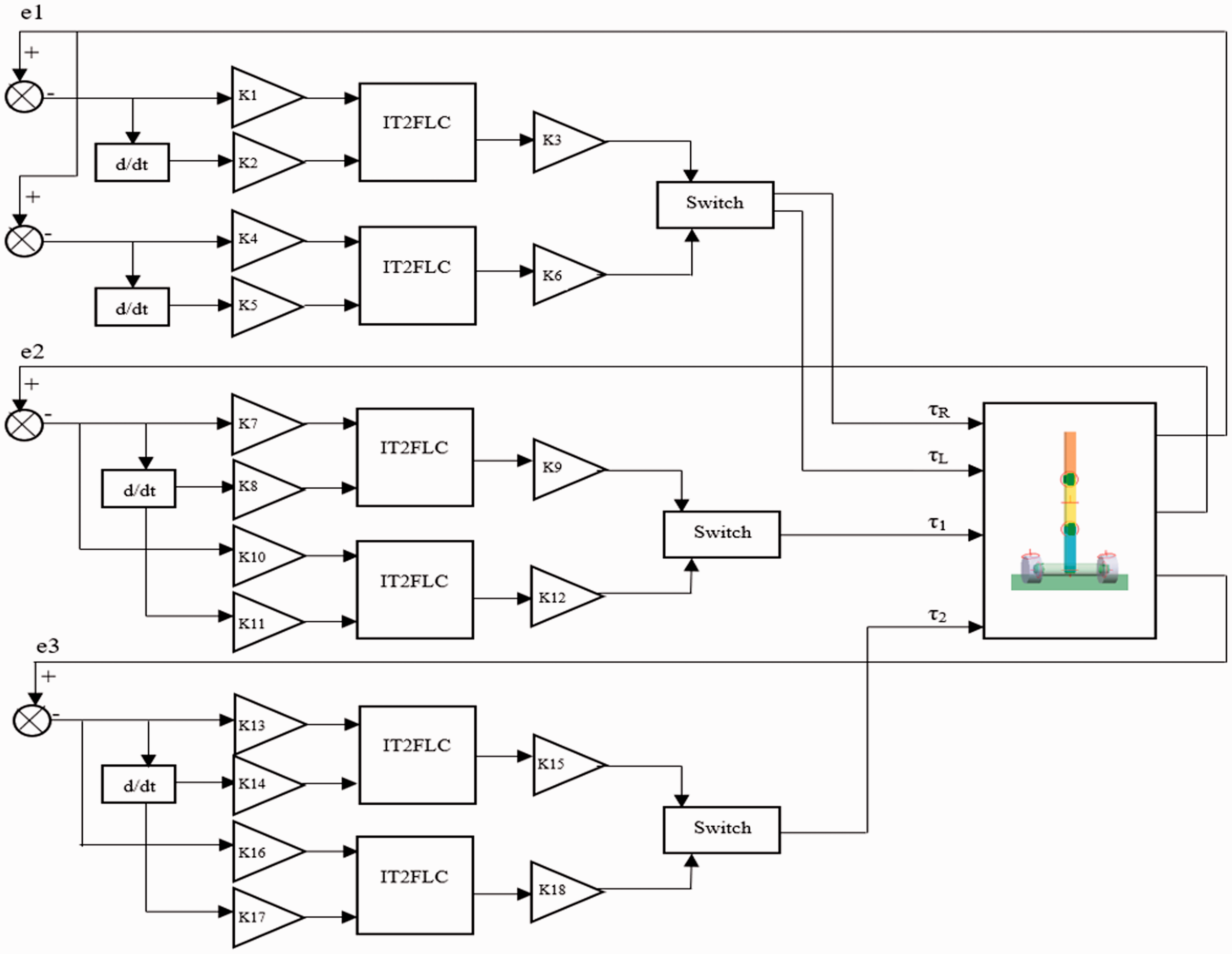
Simulink block diagram block diagram.
An optimization algorithm is proposed to find the optimal values of input output value gains and IT2FLC parameters which are σ and δ for stabilizing triple links inverted pendulum on two-wheeled system. Conventionally, heuristic tuning of the control parameters was used but such heuristic method does not guarantee that it will produce the best result. A global optimisation mechanism such as spiral dynamic algorithm (SDA) and particle swarm optimization (PSO) is necessary to improve the system performance. Due to its significant advantages over other searching methods, an optimization approach is used to optimise the control input and output gains along with IT2FLC control parameters
In this study, the objective of fitness function of the optimization is to minimize the error of angular position of Link 1, angular position of Link 2 and angular position of Link 3, while the system stabilizes these three links to ensure the stability of triple links inverted pendulum on two-wheeled system at the upright position. The root mean square error (RMSE) was chosen as the fitness function in this work,

The fitness function of the system in this research is a summation of RMSE functions of the angular position by taking the sum of weightage of all three links, where the weight vector of this system is [w1 w2 w3] = [0.4 0.3 03]. Noted that w1 represents weight at Link 1, w2 represents weight at Link 2 and w3 represents weight at Link 3 respectively. Weight at Link 1 was chosen to be the highest ratio because Link 1 is more crucial in stabilizing the whole system compared to Link2 and Link 3. The fitness function is, Fitness Function = w1MSE1 + w2MSE2 + w3MSE3, where
Spiral dynamic algorithm
SDA is known as a metaheuristic optimization inspired by natural spiral patterns such as tornado, hurricanes, and galaxy introduced by Tamura and Yasuda,
42
whose initial work was focused on two-dimensional problems and later extended to nth dimensional problems. The most essential aspect in SDA is the balanced combination of exploration and exploitation strategies. In SDA, all the search agents are designed to move from the outermost area to the centre of the spiral and move toward the centre of the spiral as the number of iterations increase. This is known as the intensification phase where it happens in the inner area of the spiral toward the centre. The mathematical model for SDA is defined as
8

Figure 6 shows a couple of examples of spiral shapes in SDA and movements of the search agents from the outermost area towards the centre of the spiral. Figure 7 shows a flowchart of SDA implementation. 8
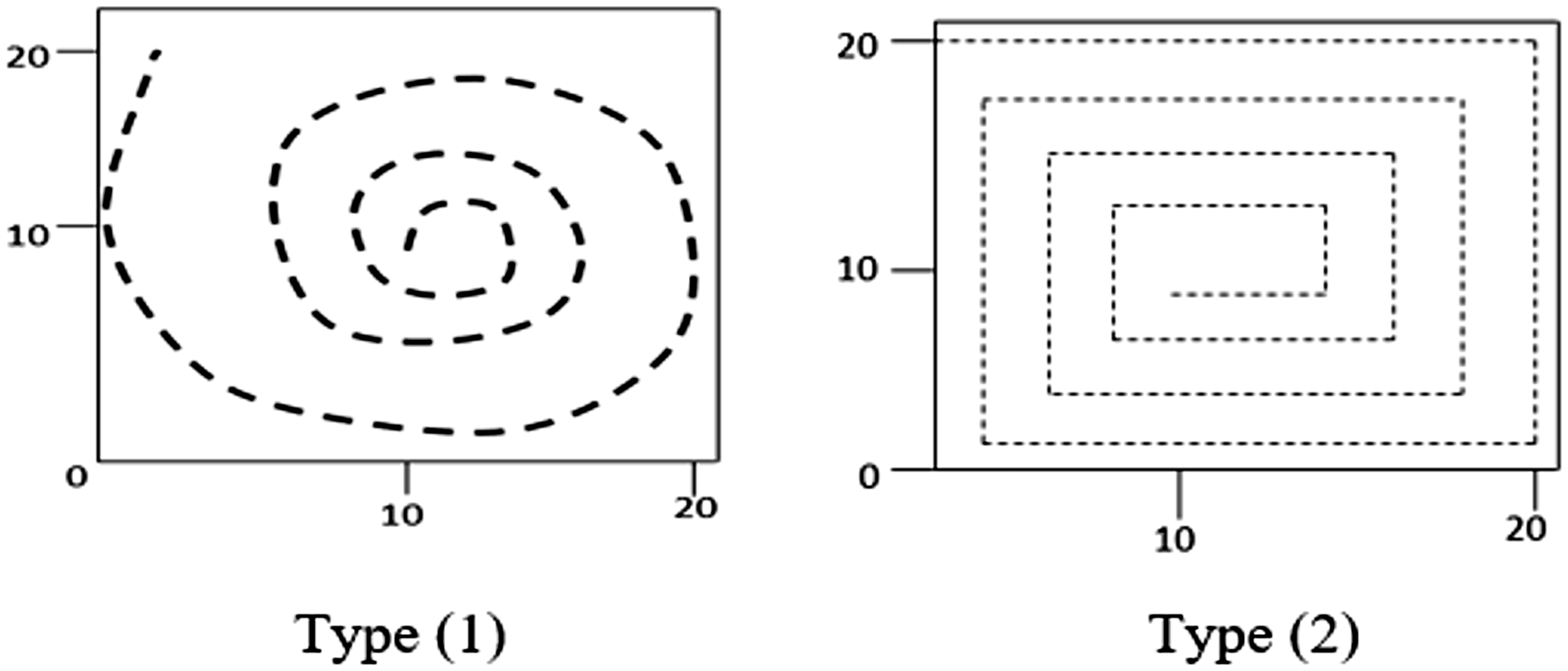
Types of spiral shape in SDA. Type (1) θ = π/4; Type (2) θ = π/2.
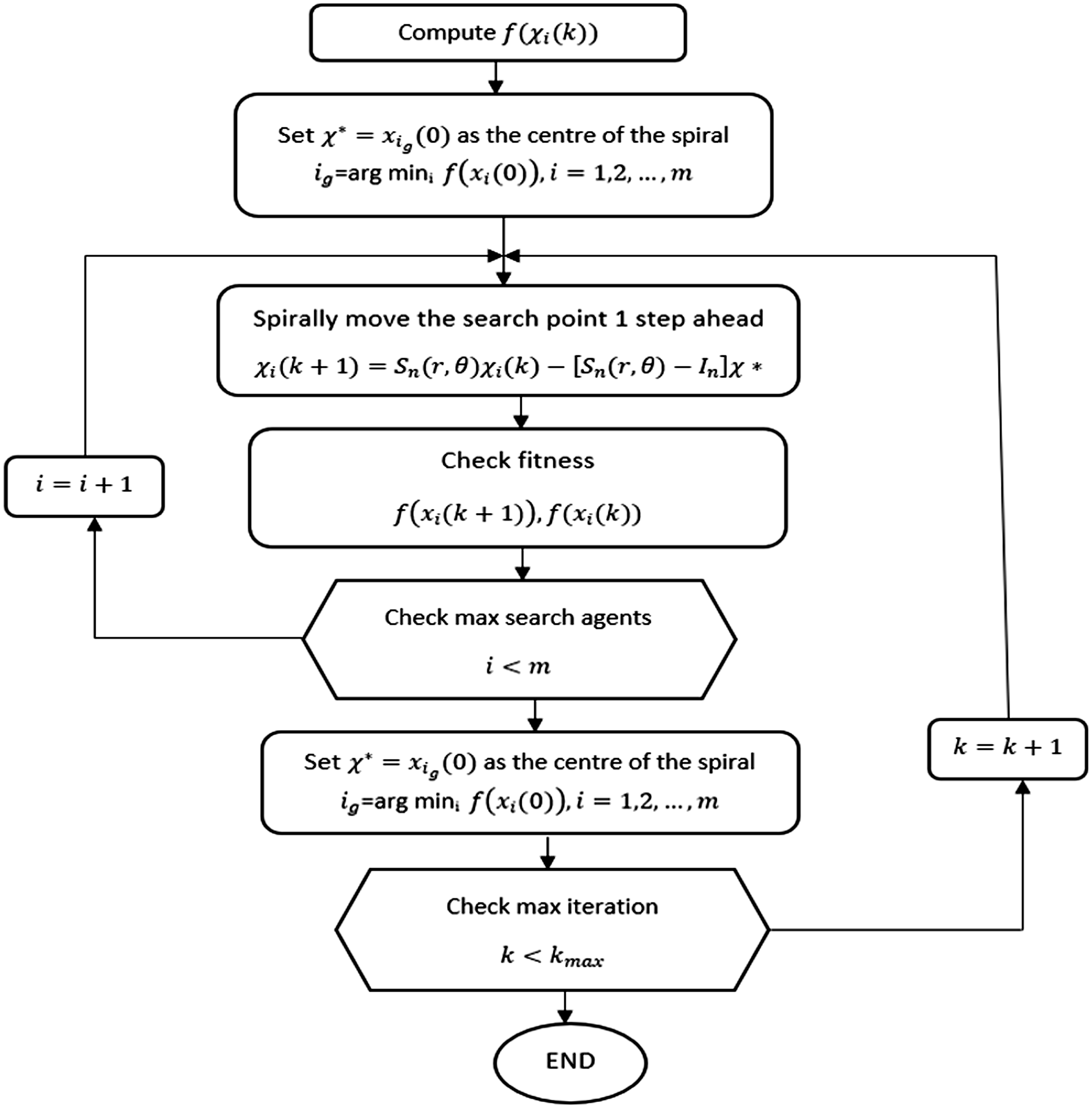
SDA flowchart.
In this work, radius, r = 0.95 and θ = π/4 are used for the spiral dynamic trajectory. The number of search agents is 50, while the number of iteration used in this work is 40. The objective of this optimization is to minimize the angular position error and manage external disturbance. All the 18 inputs and output gains along with δ and σ are used in determining the size of membership function in the IT2FLC.
Particle swarm optimization
PSO is one of the metaheuristic techniques inspired by the behaviour of group of animals for instance flock of birds and the schools of fish. PSO was introduced by Eberhart and Kennedy in 1995 37 and has been applied in various applications such as signal processing, optimal design, and data mining. PSO uses a population-based method where the state of the algorithm is represented by population and modified repeatedly until the objective is achieved.37–40
In PSO, the particle will move based on the current optimum particles. All particles will keep their tracks in the area in which the best solution or pbest is achieved. The best value among all the particles is the global best, or gbest, and is obtained by considering finesses of all the particles in the population. The concept of PSO is to update the velocities and positions of each particle towards its pbest according to equations (8) and (9)


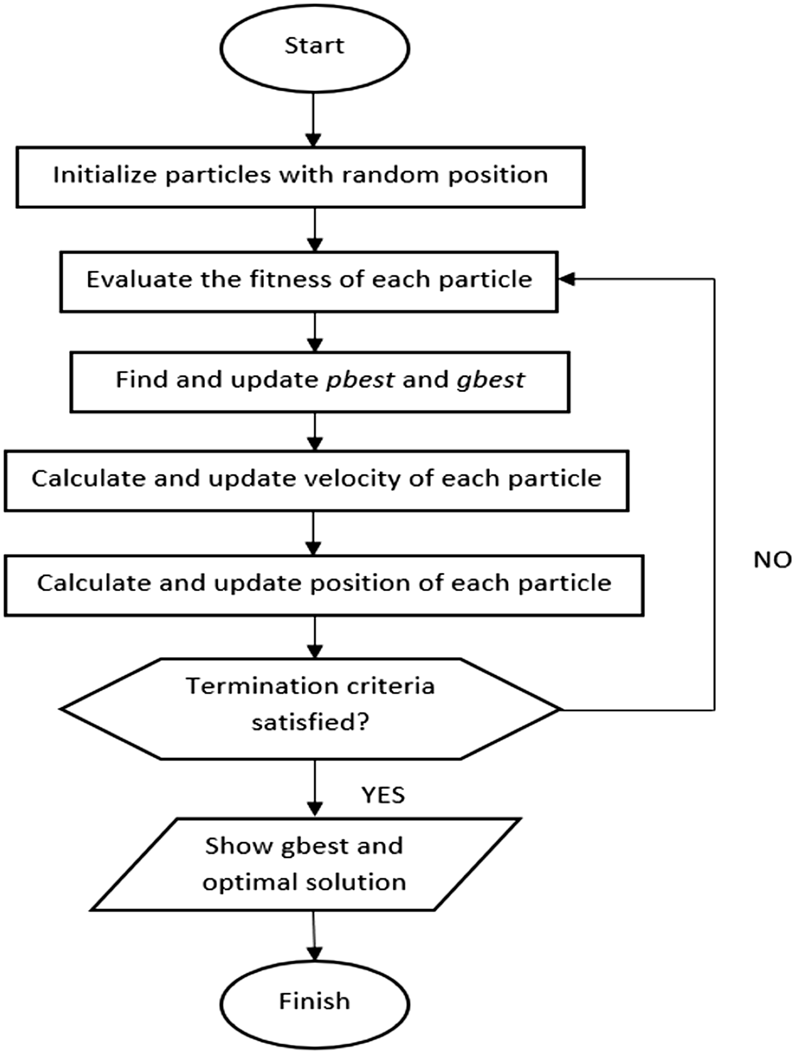
Flowchart of PSO.
Similar to SDA, PSO is used to find optimal values for the 18 input and output gains of the system and the σ and δ values for membership function of IT2FLC. These 20 parameters need to be optimized to enhance the performance of IT2FLC control in triple links inverted pendulum on two-wheeled system.
Results
The results of this study are presented and discussed in detail with reference to the objective of this study, which is to assess the effectiveness of implementing IT2FLC based on PSO on triple-link inverted pendulum on two-wheels system. The results are obtained in simulated exercises using an integrated Matlab/Simulink and SimWise 4D environment. Two optimization algorithms, namely PSO and SDA are used in the design of the controller and a comparative assessment of the system performance is carried out.
Fitness function for optimization algorithm
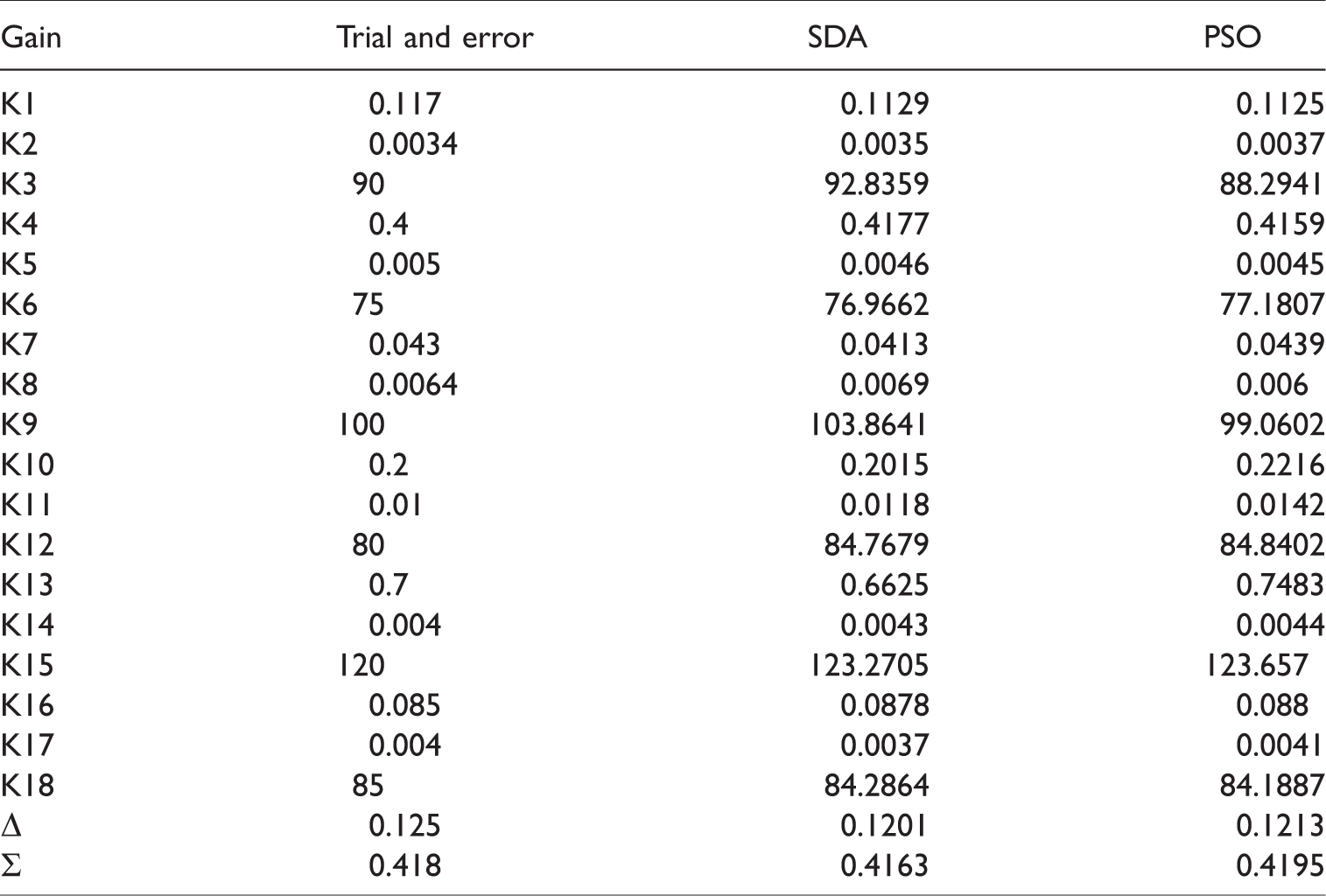
Figures 9 and 10 show the convergence graphs of SDA and PSO as function of number of iterations, respectively. As noted, PSO has performed significantly better than SDA, where the PSO and SDA began their exploration phases with fitness function values of 0.01281 and 0.01769, respectively. The exploitation phases of the algorithms began when the fitness function values decreased to 0.0077 for PSO and 0.01753 for SDA. The best fitness function value for PSO was 0.00578, while for SDA it was 0.01752. This shows that PSO has a better convergence compared to SDA. A trial and error approach was also used for obtaining the system input and output gains and the σ and δ values for membership function of IT2FLC. These are shown with optimised values in Table 3.
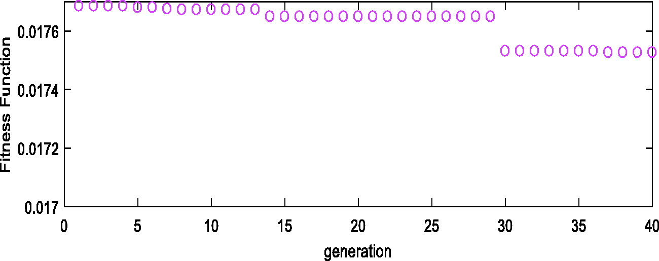
Fitness function graph for SDA optimization.
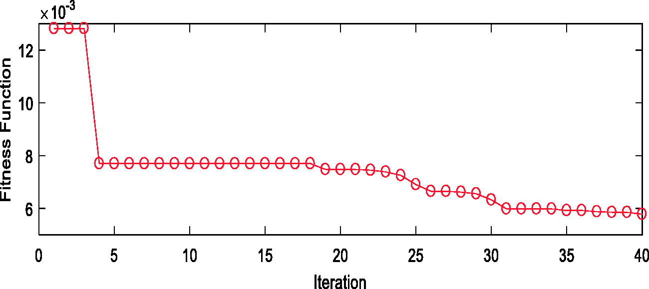
Fitness function graph for PSO optimization.
Input output gains.
Stability control
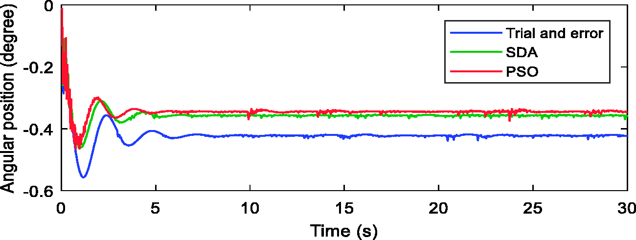
The main objective for this research is to achieve stable performance of the triple-link inverted pendulum on two-wheels system. The objective is achieved by using the input output gain values obtained in the control system. The values will determine the control torque for actuating the motors. The system performances using the control parameters obtained by the trial and error, SDA and PSO approaches are shown in Figures 11 to 13 and Table 4.
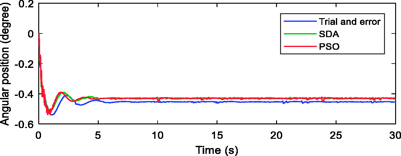
Angular position of Link 1.
Angular position of Link 2.
Angular position of Link 3.
Position errors using the trial and error, SDA, and PSO approaches.
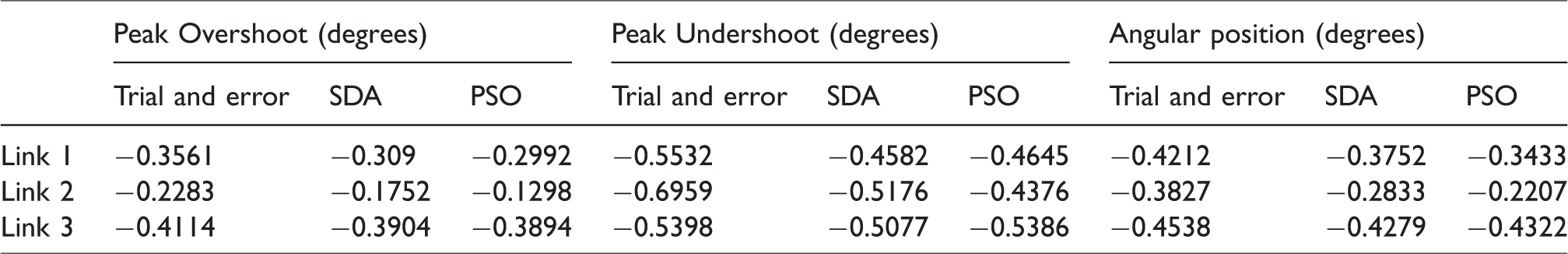
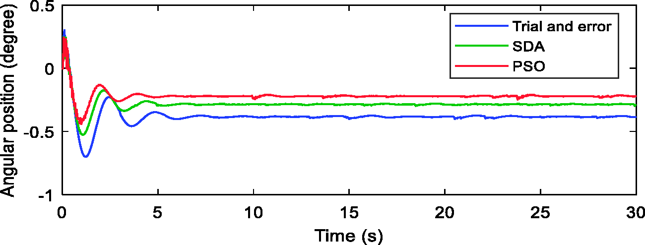
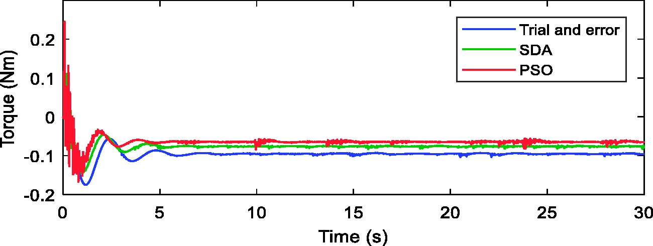
The performances shown in Figures 11 to 13 and Table 4 are assessed in terms of peak overshoot, peak undershoot, and angular position for all the three links. As noted the PSO-based system has performed well for both Link 1 and Link 2 in angular position as the errors are relatively smaller than those achieved with SDA and trial and error methods. As for link 3, the SDA-based system performed slightly better than PSO, where the angular position error with SDA was –0.4279° compared to PSO-based error of –0.4322°. Figures 14 to 16 show the control effort (torque) generated for stabilizing the three links. As noted the links settled in 5 s but fluctuated in the early stages, as expected.
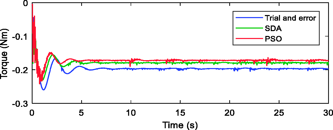
Torque value at Link 1.
Torque value at Link 2.
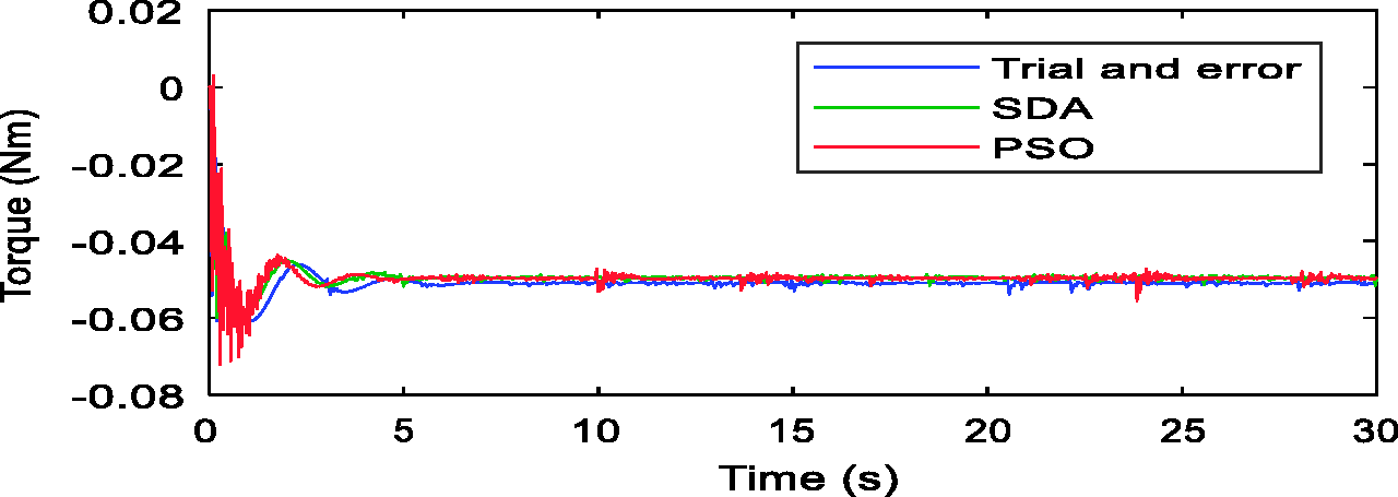
Torque value at Link 3.
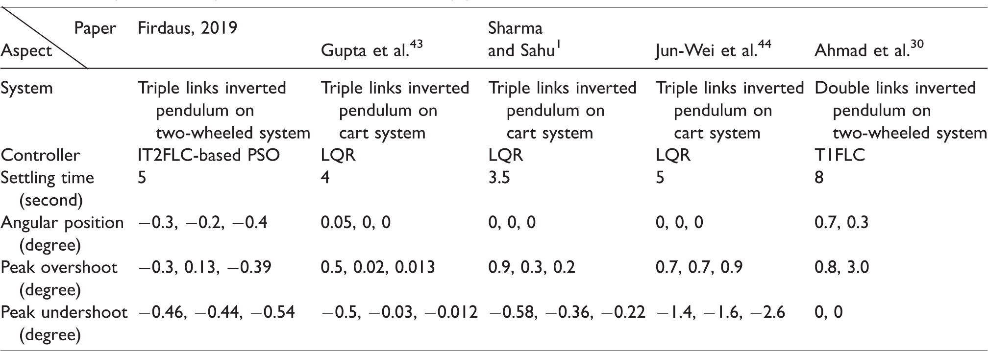
In comparison to previous research done on triple-link inverted pendulum system, the current result is better by 66% and 53.6% when compared to triple-link inverted pendulum on cart system in Sharma and Sahu 1 in terms of peak overshoot. This is a very significant improvement because even though the pendulum on cart system has been shown to have a better stability compared to that on two-wheels system, the current system has outperformed the inverted pendulum on cart system. Moreover, the system in Sharma and Sahu 1 has used conventional mathematical modelling which cannot satisfy a real-world system compared with the current system, which uses CAD-based software SimWise 4D that is able to retain the complexity and flexibility of the system.
Comparing the results achieved a two-wheeled system described in paper, 30 one notices that the system in the two-wheeled system needed approximately 10 s to achieve stability, while the current system only needs 5 s to achieve the same goal even though this system is more complex with three links, while the two-wheeled system in Ahmad et al. 30 is a double-link system. Moreover, the angular position for the system in Ahmad et al. 30 was maintained at 0.7° for the first link and 0.3° for the second link. The current work shows improvements of 33.3% for the first link and 51.4% for the second link in terms position error. Table 5 shows the complete table of performance comparison with previous work in stability focuses on lower vibrations for the system.
Comparison with previous work based on stability performance.
Disturbance rejection
In order to test the robustness of the controller, disturbances were applied to the system and the system response assessed. The disturbances considered were in the form of pulses applied at the back of Link 3.
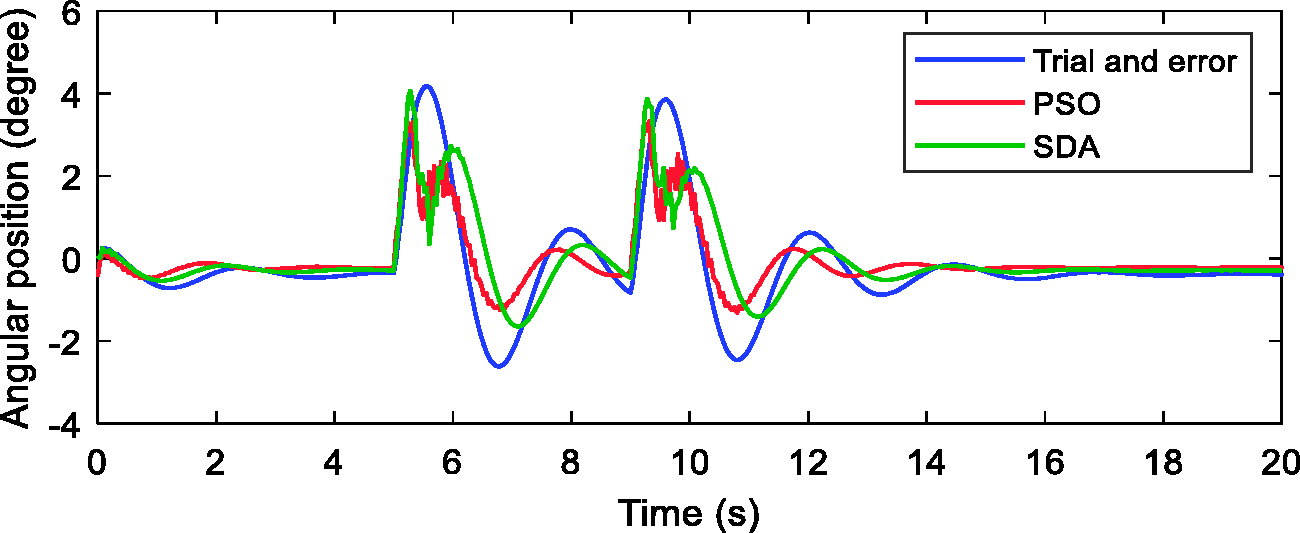
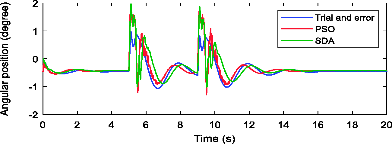
Based on the graph shown in Figure 17, the maximum disturbance rejected by PSO was 50 N, while by SDA it was 42 N, and by trial and error method was 35 N. This shows that PSO was the best optimization for this triple-link inverted pendulum on two-wheels system. Figures 18 to 20 show the system responses when the disturbance was applied at 5 and 9 s influencing the system to move forward and needed about 3 s to achieve stability back after it had been disturbed. It is noted that the trial and effort-based system was affected the most due to application of the disturbance. It is further noted that Link 2 was the most affected as it moved up to 4° for SDA and trial and error method but with the PSO, the system moved to 3.8° only.
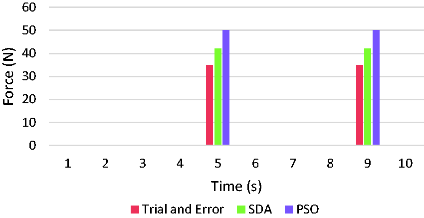
Maximum disturbance at Link 3.
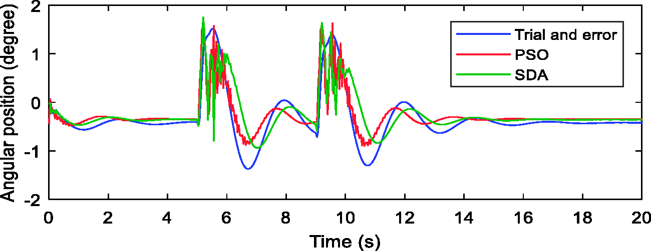
Angular position of Link 1.
Angular position of Link 2.
Angular position of Link 3.
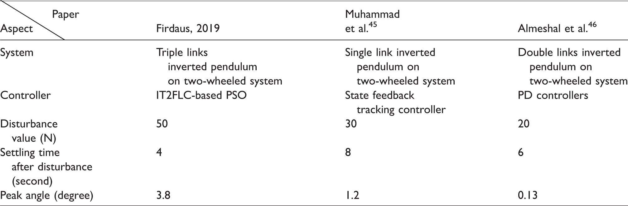
Table 6 shows the comparison done on previous work in two-wheeled mobile robot since there are no work found on disturbance rejection for triple links inverted pendulum system. From this table, the proposed controller managed to withstand the highest value of force applied to it compared to other with 50 N. Moreover, this system has the lowest settling time with 4 s, while system proposed by Mustafa need 8 s and Almeshal’s system need 6 s to settle.
Performance comparison on disturbance rejection with previous work.
Conclusion
In this paper, a control design approach by adoption of optimization techniques based on SDA and PSO has been proposed in the paper for tuning of control parameters of IT2FLC for triple-link inverted pendulum on two-wheels system. The aim of the optimization is to enhance the efficiency of the system in terms of stability and disturbance rejection. A proposed controller has been successfully implemented and tested in this paper, and the performance of the system was observed within simulated exercise through SimWise 4 D visualization software integrated with Simulink in Matlab.
The results have shown superior performance of the PSO-based system over SDA-based system by 9.3% and 28.4% in angular position errors of Link 1 and Link 2, respectively. Furthermore, peak values of SDA were higher than PSO which means that PSO has lower noise than SDA and more stable; this system has been proven to have lower peak overshoot and settling time compared to previous work.
It has been proved that the proposed controller in this paper managed to withstand higher disturbance compared to previous work by 66.7%. Moreover, the settling time after disturbance that was applied has significantly improved with only 4 s compared to 8 and 6 s from previous research. In the future work, the system will be test on linear motion in smooth surface, rough surface and inclined surface to further test the robustness of the controller. Besides that, this controller could be implemented in real-hardware applications.
Footnotes
Declaration of conflicting interests
The author(s) declared no potential conflicts of interest with respect to the research, authorship, and/or publication of this article.
Funding
The author(s) disclosed receipt of the following financial support for the research, authorship, and/or publication of this article: The work presented in this paper was supported by Graduate Research Assistant (RDU170502) from Faculty of Electrical and Electronics Engineering, Universiti Malaysia Pahang.