
Abstract
A stainless-steel cantilever multistage centrifugal pump was taken to study the transient response characteristic. The axial locus under different working conditions was tested experimentally and compared in detail. The results show that the gyroscopic effect increases the radial displacement located near the end element, and the amplitude of the radial displacement of the pump body increases with the development of unbalance mass. The dynamic sealing force of wear-ring could enhance the stability of the rotor system, and effectively reduce the amplitude of the radial displacement. The axis locus under variable flow rates is different when the fluid excitation was loaded. The increasing tendency of the maximal radial displacement appears exponential with the enhancement of fluid added mass when heterogeneous fluid added mass is taken into consideration. The experimental results exhibit that the axis locus is various under different working conditions, and there exists misalignment and eccentricity phenomenon in the multi-stage pump rotor system.
Introduction
Because of the unique advantages of compact structure, reliability, easy installation and convenient maintenance, the cantilever multistage centrifugal pump is gradually substituting for the traditional double-supported multi-stage centrifugal pump in many fields, such as the water supply system, petrochemical, metallurgical power, water conservancy project and agricultural irrigation. 1 However, the critical questions of the stability of the multistage pumps include axial force balance, 2 characteristics of rotor dynamic, 3 and anti-wear performance of overflow components. In the process of heightening the performance by improving the structure of multistage pump, the problem rotor dynamic characteristics facing with is rather complex and hard for deeper research. 4 By simplifying the rotor system model, the critical speed and rotor modal could be calculated, which will play an important role in guiding the actual production. 5 Additionally, the rotor system would be influenced by the force of the fluid during the actual operation because of its special structure, which has significant impact on dynamic characteristics. 6
In recent years, since the stability of rotor system is the dominant factor affecting the life of turbomachinery, so plenty of research on the rotor dynamics has been conducted by theory analysis and numerical simulation.7,8 Transient dynamic models are constantly used to predict the transient vibration of complex rotor system, and its numerical solution could be obtained by numerical integration technology.9,10 Lewis 11 put forward the analytical solution which is suitable for the rotor system reaching the critical velocity by certain acceleration, the basic characteristics of the amplitude of the transient vibration are studied based on the approximate method, and the analytic expression of the motion of the simple Jeffcott rotor geometric center and the exact amplitude of the transient vibration of the rotor system are derived. Jiang et al. 12 simplified the fluid force in the impeller to various fluid mass and used the Newmark implicit algorithm to simulate the transient response. Bouaziz et al. 13 researched the effect of angular misalignment on the transient dynamics of a rotor-Active Magnetic Bearings (AMBs) system using the Newmark time integration method, and the result of dynamic responses confirmed the significant influence of the transient regime on the dynamic behavior of misaligned rotor. Fu 14 proposed a non-intrusive interval precise integration method (IPIM) to analyze the transient unbalance response of uncertain rotor systems and validated its accuracy by comparing with the scanning method in simulations. The results showed that the IPIM has good accuracy in vibration prediction of the start-up transient process. Gyekenyesi 15 studied the dynamic response of a rotor system by utilizing a general-purpose finite element (FE) code. A heat transfer solution was incorporated to attain the temperature distribution based on the defined boundary conditions, and the stress stiffening and spin softening were also considered. The results indicated that the factors have a significant impact and should not be neglected.
As a result of the unique single-support structure of the cantilever multistage centrifugal pump, the influence of the gyroscopic effect is more apparent, and the calculation difficulty of dynamic characteristics is larger than that of other pumps.16,17 In this paper, the numerical simulation is conducted based on CFD, various kinds of fluid excitation are determined, and then the transient response of the cantilever multistage centrifugal pump is analyzed in different circumstances based on SAMCEF software. The results could provide reference for the research of the stability and reliability on the cantilever multistage centrifugal pump.
Physical model and mathematical model
Physical model
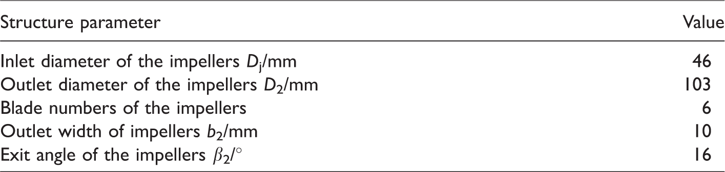
The research object was a four-stage stainless-steel cantilever centrifugal pump, and the practical structure of the pump is shown in Figure 1. The designed flow rate Qd is 10 m3/h, the head of each stage is 8 m, rotational speed is 2800 r/min, and the specific speed ns = 113. The main geometric parameters of the impeller are shown in Table 1.
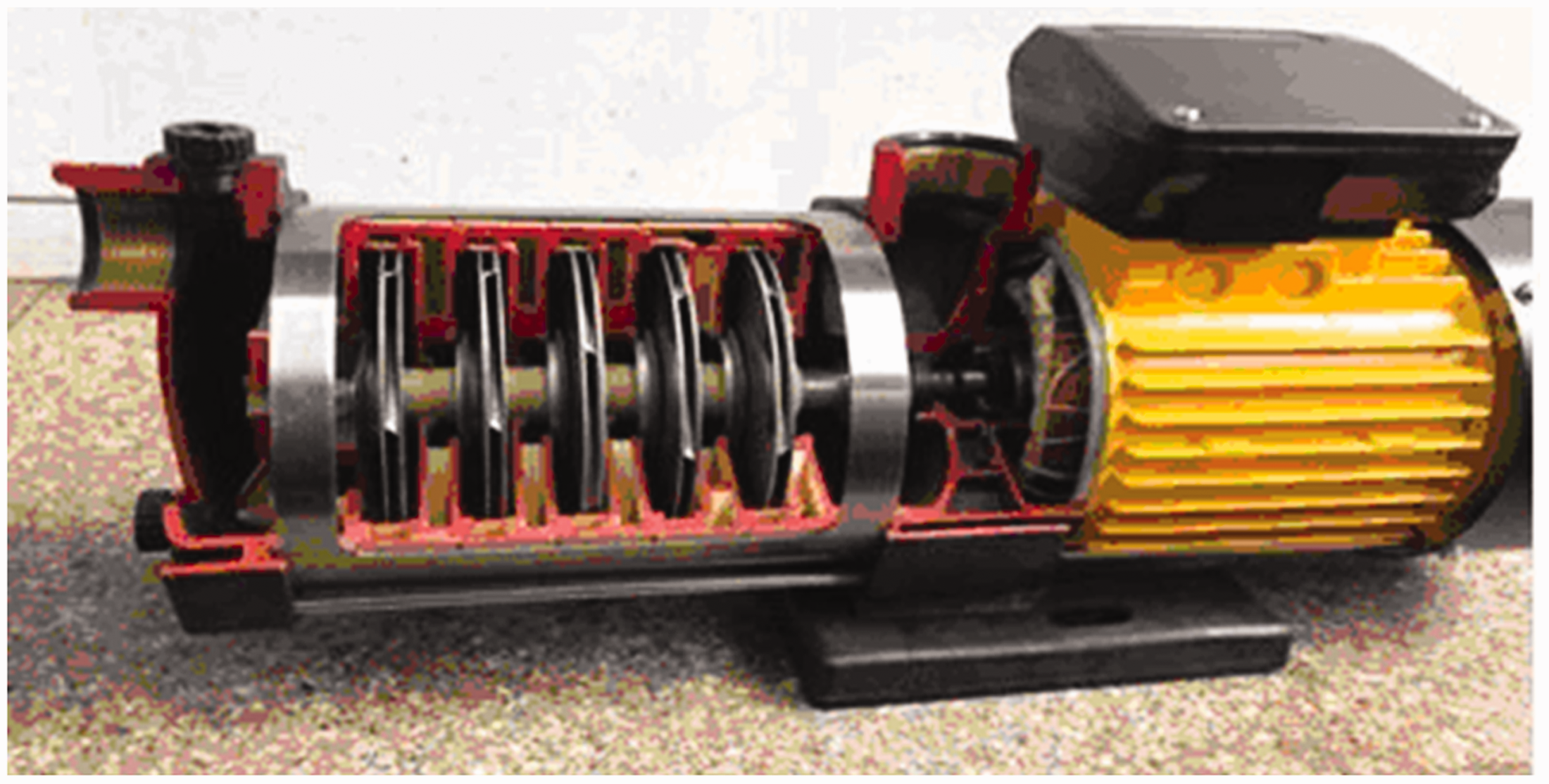
Cantilever multi-stage centrifugal pump.
Main structure parameters.
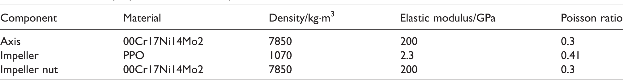
The model of the rotor system structure was established by Creo3.0. Due to the sophisticated practical structure and large scale of calculation, a great deal of deformation elements would be generated according to the characteristic of SAMCEF software. Therefore, the axial end and the interface of the lock nut were simplified, as shown in Figure 2. The bearing is kind of deep groove ball bearing (model number 6202). The material property of each part is shown in Table 2.
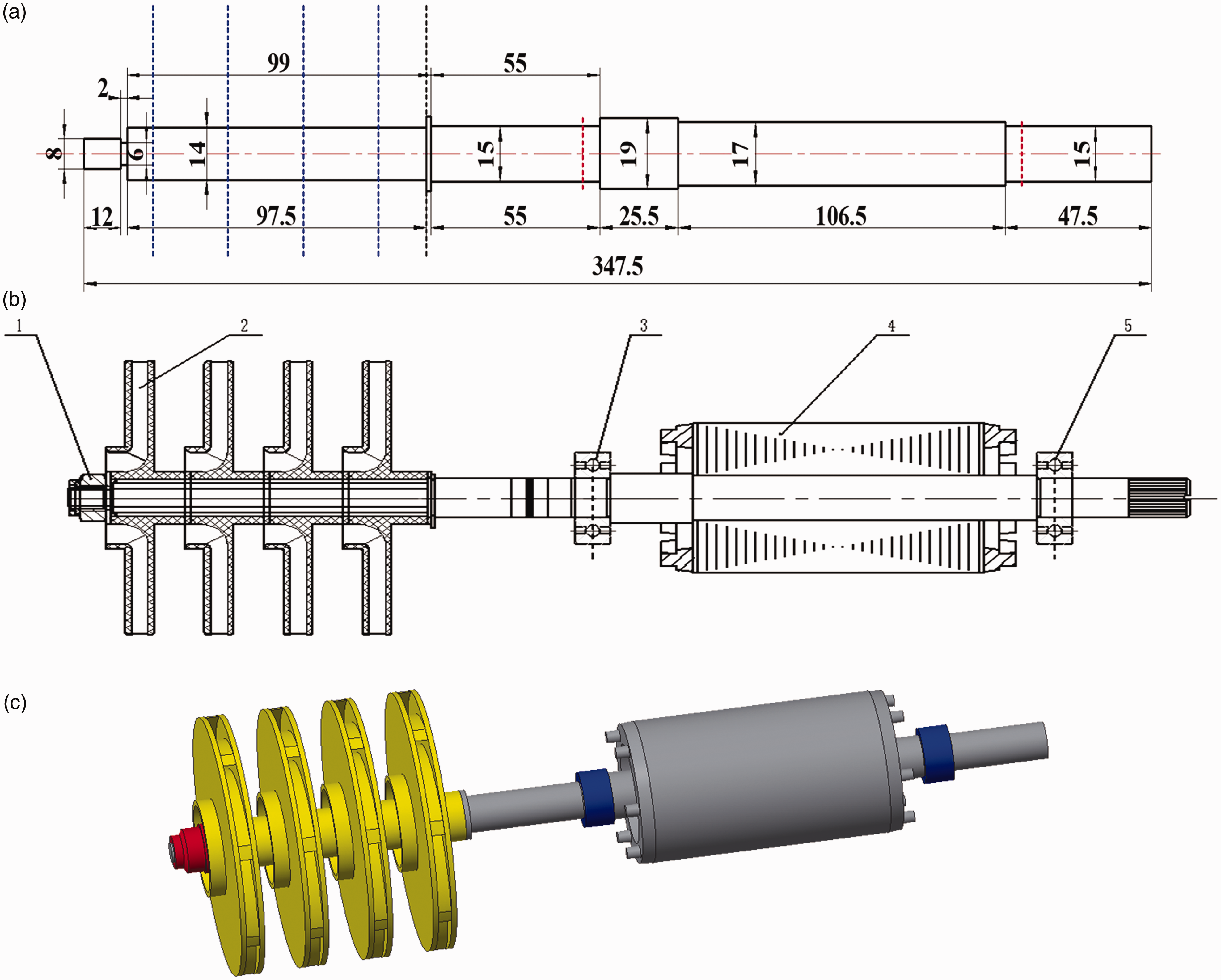
The rotor system of cantilever multistage centrifugal pump. (a) The dimensional of shaft; (b) 2D model. 1. Impeller nut. 2. Impeller. 3. Bearing A. 4. Axis. 5. Bearing B. (c) 3D model.
The material properties of rotor components.
Mathematical model for solving transient response
Rotating machinery should undergo various transient processes such as start-up, shutdown and load changing conditions. In these processes, the active forces and loads on the rotor would go through complicated changes to achieve a new balance. Therefore, the transient response of the rotor system is more intricate than the steady state, and the transient response analysis is an important content to study the dynamic characteristics of the shafting.
In this paper, Riccati transfer matrix method18,19 and Newmark-β method20,21 were used to solve the transient response of multi-degree-of-freedom rotor system.
According to the Newmark-β method and taking γ = 1/2, then there is
In the formula,
When the node i and the right axis segment are treated as one component, the transient transfer matrix of this component is

By the Riccati transform 

The
Starting from the initial condition of the initial moment
The preparation of calculation and analysis
The calculation of rotor unbalance mass
The allowable unbalance mass of the rotor could be calculated as follows

In the formula,
The balance precision level is directly proportional to the eccentricity and angular rotational speed, so the permitted maximal eccentricity and residual unbalance mass in the rotor system are presented as follows


The confirmation of fluid excitation base on CFD
The fluid excitation loaded at the rotor contains the radial force (abbreviated as RF), axial force (abbreviated as AF) and torque acting on each impeller and axle nut. The simulated performance based on CFD was compared with the experimental data, and the deviation of the curves which denotes the relationship between the flow rates-head, flow rates-power and flow rates-efficiency was limited to 3%, as shown in Figure 3, which indicates that the simulated result acquired good consistence with the experiment.
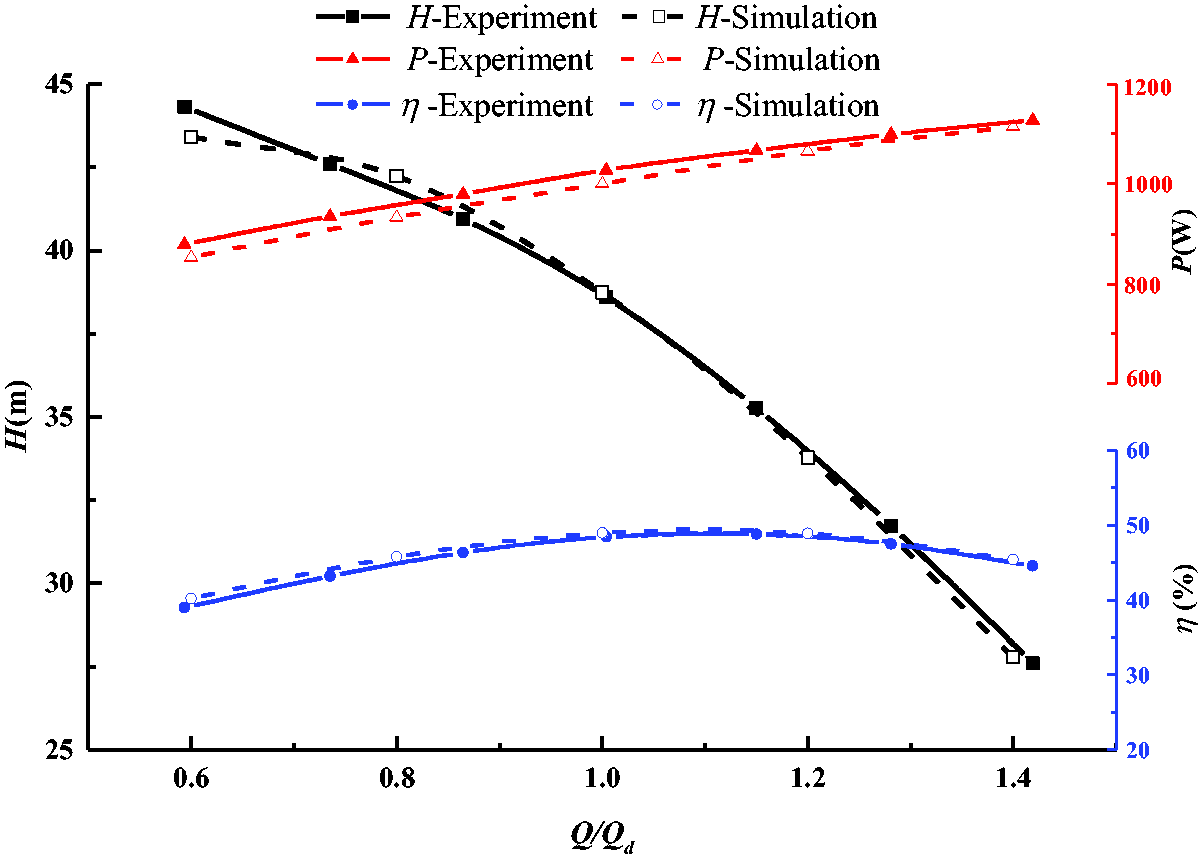
Comparisons of pump performance between the simulation and experiment. (a) The change trend of radial force in one cycle; (b) the time domain distribution of axial force in one cycle.
The RF under designed flow rate has been obtained by post integration, as shown in Figure 4(a). It can be seen that the RF acting on the impeller at each stage is less than 0.14 N, and the distribution is nonuniform. The RF of the impeller nut is not much different from that of the first three impellers. The AF under five different flow rates is shown in Figure 4(b), and it can be seen that the total AF in one cycle appears significant periodicity. As the flow rate increases, the total AF of the multistage centrifugal pump decreases, which could attribute to that the increase of the flow rate causes the head to decrease, so that the pressure difference between the front and rear covers of the impeller is relatively small, and the AF acting on the impeller is also reduced. However, the amplitude of the fluctuation increases. At the designed and large flow rate, the total AF appears 24 peaks and troughs in one rotation period with the pulsation period of 15°, which is consistent with the minimum common divisor of the number of blades of the impeller and guide vane.
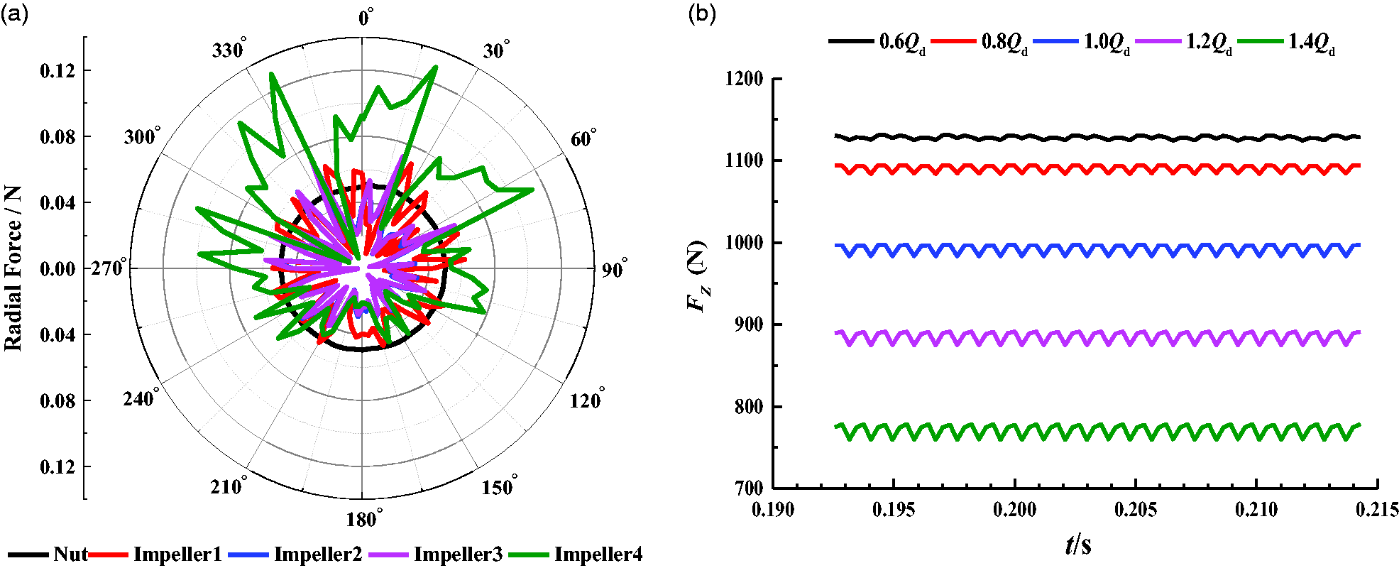
The distribution of radial force and axial force. (a) The change trend of radial force in one cycle; (b) The time domain distribution of axial force in one cycle.
The pre-processing settings of calculation
In order to gain the impact of the unbalance effect on various stage impeller, the unbalanced mass with the same phase was applied on each stage impeller. The process of the rotor system from start-up to normal operation in air medium was simulated in SAMCEF software, the rotor starting time was set to 3 s, and the normal operation time was 2 s (the rotational speed would accelerate from 0 to the rated speed, and then runs for 2 s at 2800 r/min). The total solving time was 5 s, and the imposed time step was 0.0005 s, which means that each result would be exported every 0.0005 s.
Rotor transient response under dry state
Transient response considering unbalanced mass
Due to the gyroscopic effect caused by structure, the radial displacement (abbreviated as RD) of the part which is far away from the bearing is the largest, as shown in Figure 5. It can be seen that from the impeller lock nut to the impeller and then to the bearing position, the RD and the acceleration amplitude reach the maximum at the lock nut and the minimum at the two bearing positions. Therefore, the influence of the unbalance mass on the transient response at the nut was considered preferentially.
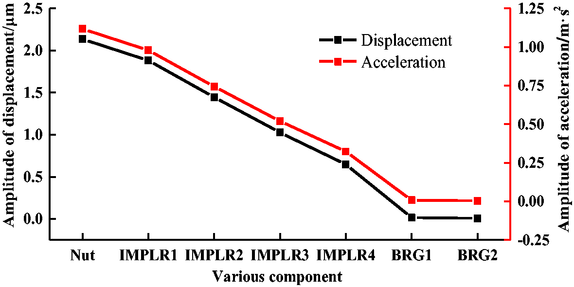
The amplitude of displacement and acceleration.
The main axis of the model is the X axis, the curves of acceleration and displacement response with time at the nut position are shown in Figures 6 and 7, and the axis locus (abbreviated in this paper as AL) is shown in Figure 8. As shown in Figure 6, the amplitude of the acceleration response in 0–1 s varies inapparently, which increases slowly in 1–2.5 s, and grows rapidly during 2.5–3 s. Because of the inertia, the acceleration amplitude does not reach the maximum at 3 s but continues to increase slowly. When the speed reaches the rated speed, the amplitude of acceleration tends to be stable.
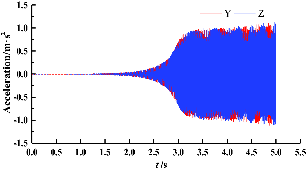
Acceleration response curve from start-up to normal operation.
Figure 7 shows the change of the RD of the nut with time in the start-up stage of 0–3 s and the normal operation stage of 3–5 s. It can be seen that the RD increases slowly with time. When the rated speed is reached, the RD reaches the maximum, and the maximal displacement is 2.14 µm. The corresponding AL is shown in Figure 8. The AL of the start-up phase diffuses from the center to the radial direction and begins to float with the increase of the displacement. After reaching the rated speed, the AL presents a ring shape.
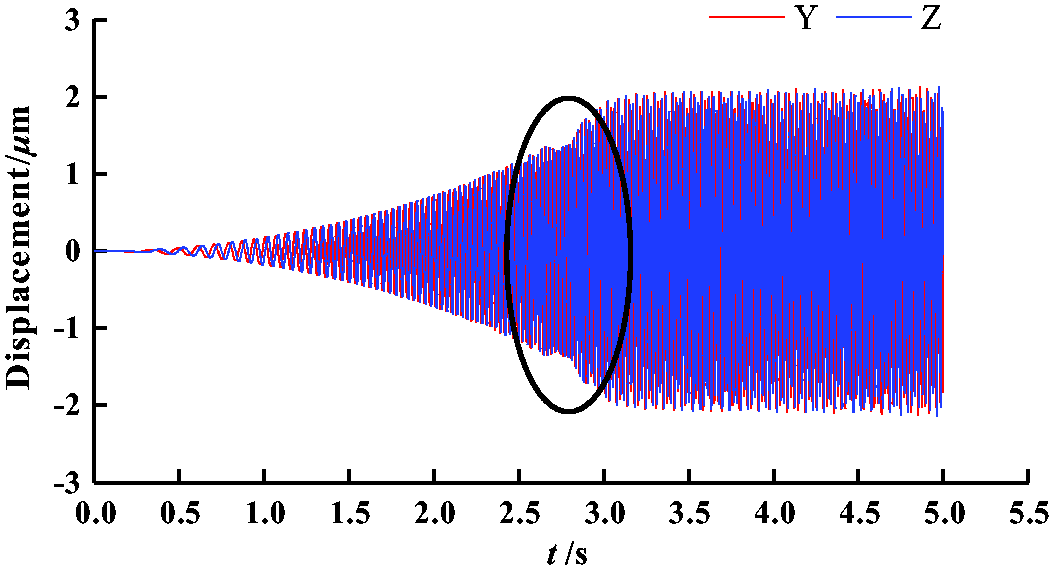
Displacement response curve from start-up to normal operation. (a) 0–3 s; (b) 3–5 s.
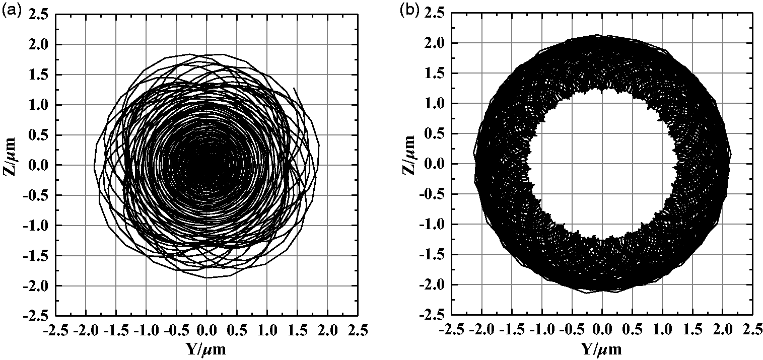
The curve of axis locus from start to normal operation. (a) 0-3s; (b) 3-5s.
For the rotor system operating in the air, the RD appears parabolic law in 0–2.6 s, while the amplitude of the displacement fluctuates during the period of 2.6–3.0 s, which is magnified in Figure 9. The displacement reached the maximum for the first time at 2.67 s, with an amplitude of 1.36 µm, followed by the second and third maximum. The time period is divided into 2.6–2.76 s and 2.76–3.0 s, and the corresponding AL are shown in Figure 10. In 2.6–2.76 s, the AL is still relatively regular; however, it becomes more chaotic in 2.76–3.0 s, and the displacement amplitude gradually rises.
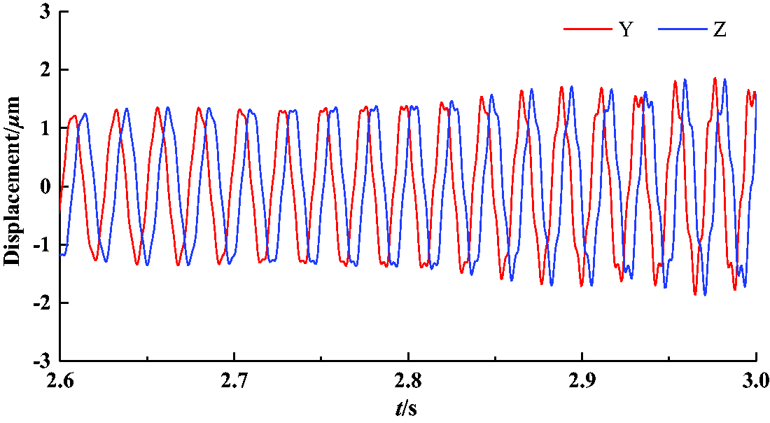
The displacement response curve of 2.6–3.0 s at the start-up stage. (a) 2.6–2.76 s; (b) 2.76–3.0 s.
The shaft center orbit of 2.6–3.0 s at the start-up stage. (a) 2.6-2.76 s; (b) 2.76 s-3 s.
The influence of unbalance mass on transient response
To analyze the effect of the unbalanced mass and the additional fluid mass on the transient response of the rotor system, the transient response of the lock nut is calculated when the unbalance mass is 0.5 g, 1.0 g, 1.5 g, 2.0 g, and 2.5 g, respectively. The calculation results are shown in Figure 11. It can be seen that from the start-up stage to the normal operation, the torque acted on the rotor increases with the raise of the unbalanced mass, and the RD of the lock nut in the Y direction increases at the same time. Furthermore, with the raise of the unbalanced mass, the instable abrupt of displacement within 2.6–3 s becomes obvious. Therefore, the vibration amplitude of the rotor can be effectively reduced by improving the precision to reduce the unbalanced moment or mass, and the stability of the rotor would be enhanced by avoiding the friction between the impeller and guide vane.
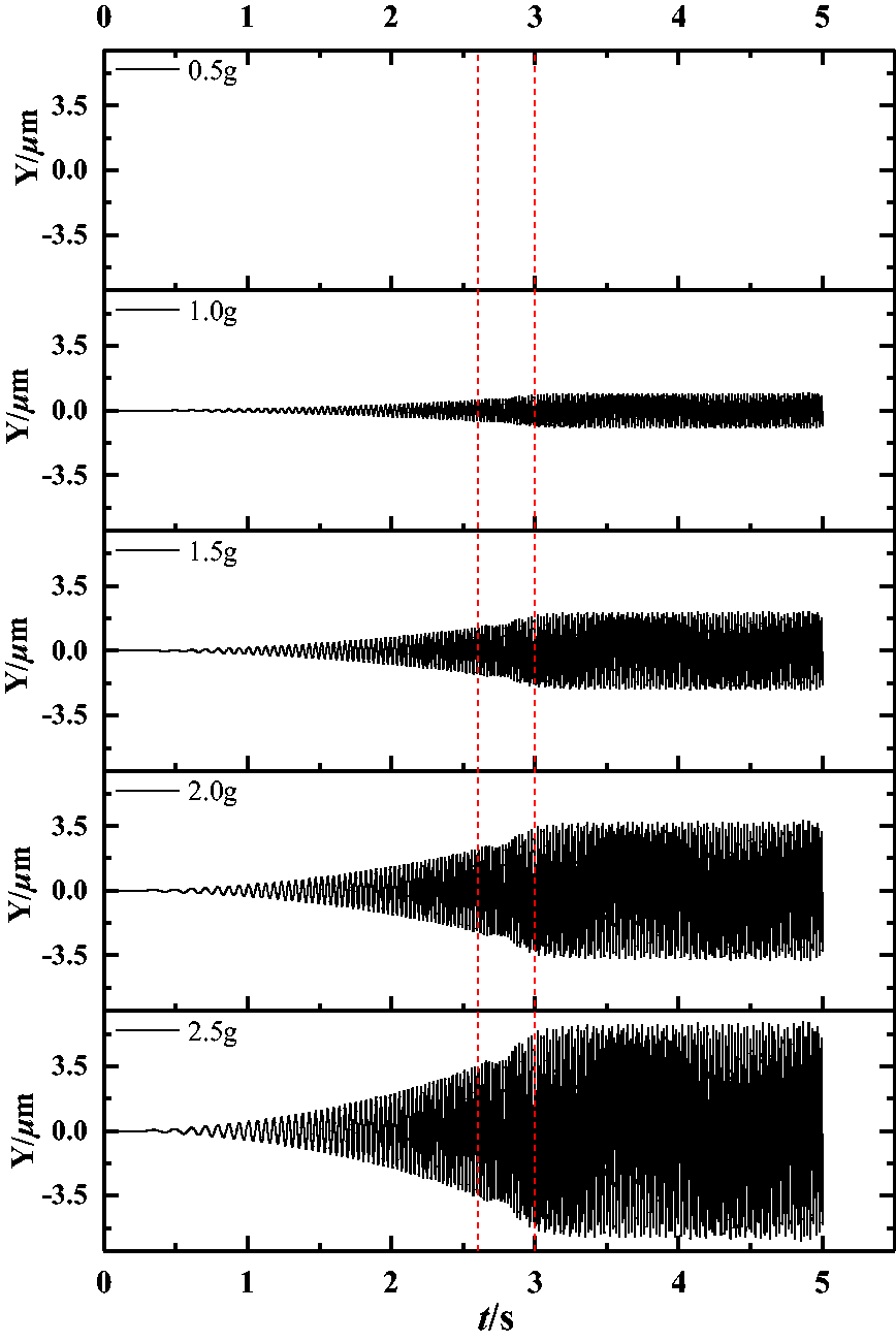
Transient response analysis of different unbalance mass.
Transient response under various start-up time
In order to analyze the effect of different start-up time on the transient response of the cantilever rotor system, the position of impeller lock nut was chosen as the research target, and the maximal RD has been calculated, respectively, when the start-up time of the rotor system reaches the rated speed in 1–5 s, as shown in Figure 12. The maximal RD at the impeller lock nut increases with the raise of start-up time. The longer the time is, the closer the maximal RD at the nut position to the RD during steady-state operation. There is a transition interval from start-up time to normal operation, with the increase of start-up time, the transition interval decreases. Among them, the interval is the most obvious when the star-up time is 1 s, and reaches the first maximum at 1 s, then reaches the second maximum at 2 s, and the transition lasts about 1 s. When the start-up time is 2 s, the transition interval decreases to 0.6 s. The maximal RD amplitude is almost unchanged when the rotational speed reaches stable at various start-up time. Since the start-up phase is an unstable transient process, it is necessary to avoid starting the multi-stage centrifugal pump too fast.
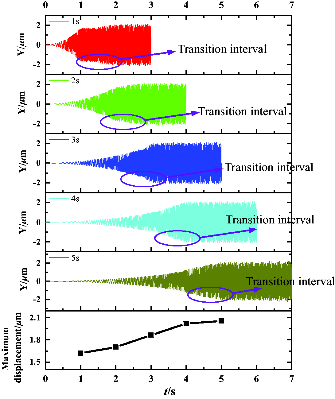
Transient response analysis of different start-up time.
Rotor transient response under wet state
The fluid excitation inside the pump body of each stage is the main reason for the vibration of the cantilever multistage centrifugal pump. In the study of rotor dynamics of fluid machinery, the AL under the dry state would be taken into account, but the influence of the fluid excitation, the seal force of the ring and the additional fluid mass are ignored because of their variability and complexity. To investigate the AL of the pump under working condition, “wet state” AL (which means the axis locus under the wet state), not only the influence of the unbalanced mass on the transient response of the rotor system, but also the effect of the dynamic characteristics of the ring, fluid excitation and additional mass of the fluid on the rotor system should be considered. The dynamic characteristic coefficients of the ring under various working conditions have been solved, as shown in Tables 3 and 4, and the 10–35% of the fluid mass in the impeller could be taken as additional mass. 23 With the development of CFD technology, the force acting on the impeller surface could be applied on the rotor system with AF, RF and torque as exciting forces.
The dynamic characteristic coefficients of wear rings at all levels under different working conditions.
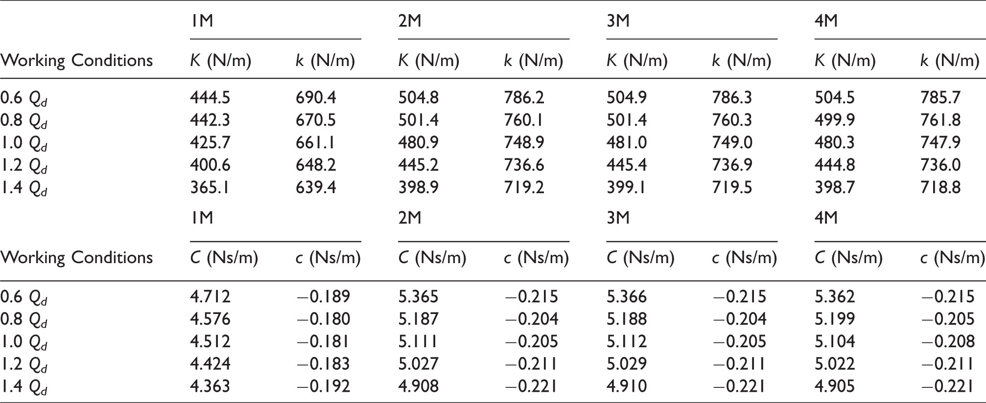
The dynamic characteristic coefficients of stage rings at all levels under different working conditions
Transient response considering the dynamic characteristic of the ring
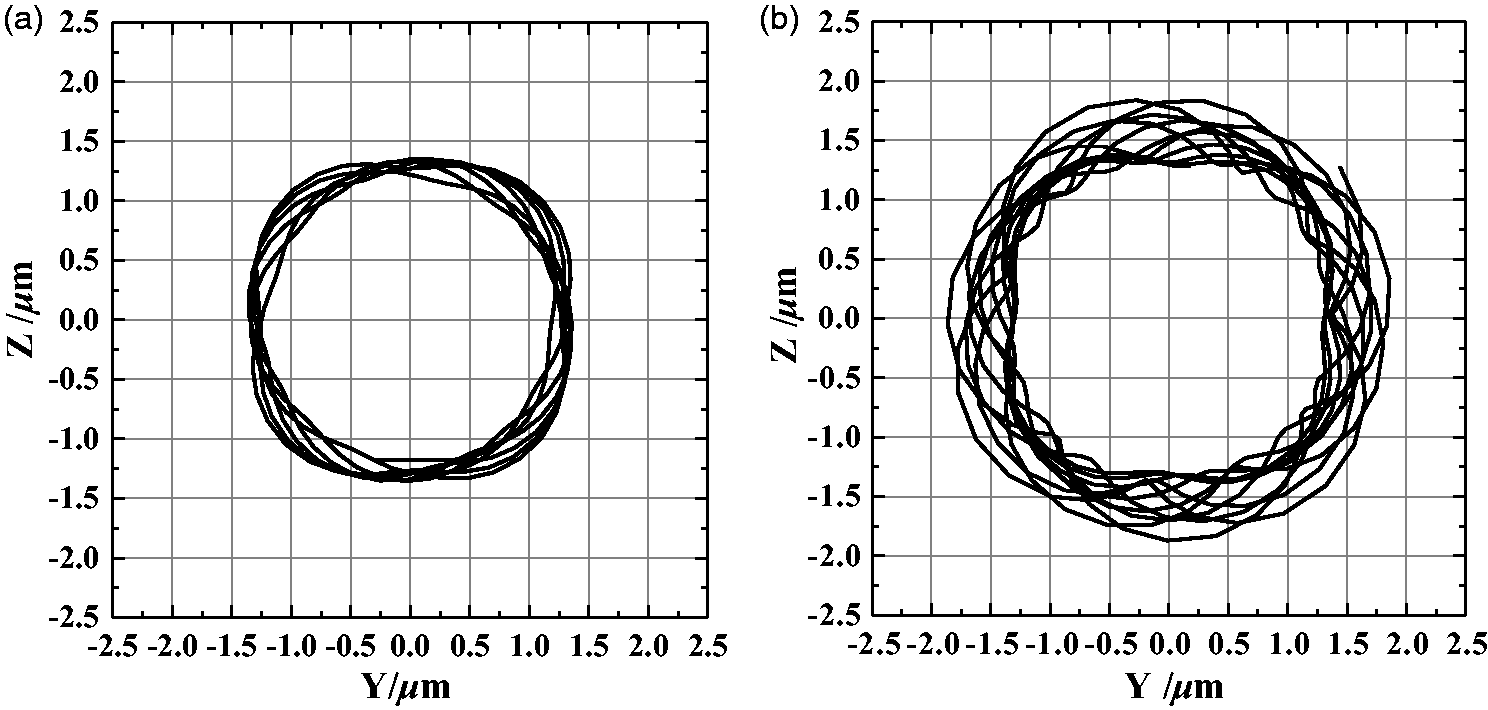
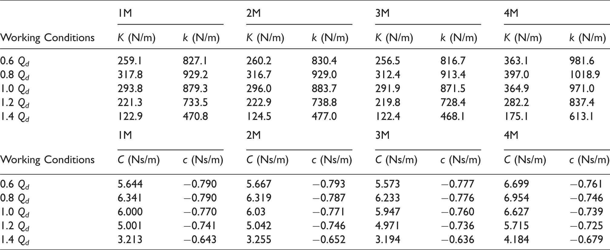
For the cantilever multi-stage centrifugal pump, the gyroscopic effect is harmful to the stability of the rotor system. During the operation, the dynamic characteristic coefficient generated by the clearance between the ring and the orifice has a certain effect on improving the stability of the rotor system. 24 Therefore, the influence of the dynamic characteristics of the ring on the transient response under the designed condition should be developed favorably, and the bearing constraints were applied at the position of the impeller ring and the inter-stage clearance. The calculated AL at the impeller nut under rated speed is shown in Figure 13. By considering the dynamic characteristics of the ring, the maximum and minimum of RD at the position of the impeller nut are 1.64 µm and 1.63 µm, respectively, and these values of the axis are 2.16 µm and 1.16 µm as shown in Figure 8(b), the AL curve is a relatively stable ring. By comparing of Figures 8(b) and 13, the dynamic sealing force of the impeller ring can improve the stability of the rotor system apparently.
The shaft center orbit of considering the characteristics of sealing ring. (a) 0.6 Qd; (b) 0.8 Qd; (c) 1.0 Qd; (d) 1.2 Qd; (e) 1.4 Qd.
Transient response considering the fluid excitation
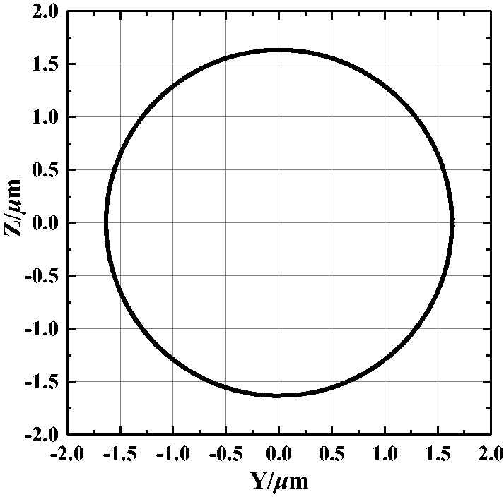
The fluid excitations of each impeller and nut calculated by CFD including the RF, AF and torque are applied to the corresponding nodes. Because of the different sealing force of the front and wear ring of the impeller under different operating conditions, the supporting function of the rotor is also variable. Applying the dynamic characteristic coefficients of the ring of all levels to the corresponding nodes, the AL of the impeller nut under various flow rates is shown in Figure 14. It can be seen that the obtained AL is various, and the eccentric phenomenon is obvious. Under 0.6Qd, the AL exhibits a fan shape and the RF distribution trend of the impellers at all levels is the same. Under 0.8Qd, the AL is more complicated, and the RD amplitude reaches the maximum, which corresponds to the complex RF distribution. With the increase of flow rates, the RD of the AL curve is smaller under 1.0Qd, and the eccentricity continues to decline. There is little difference between the AL under 1.2Qd and 1.4Qd, which is similar to the RF distribution trend of the impeller at all levels under these two operating conditions. In general, the RF is less than 0.175 N, and the maximal RD of the AL is less than 3 µm when considering the fluid excitation force under different working conditions. Under the low flow rate, the internal flow field of the pump is complicate and capricious. The AL is irregular due to the existence of vortex, second flow and other unsteady flow phenomenon. Under designed flow rate, the streamline is smooth, and the flow field is reliable. On the other hand, with the enlargement of flow rate, the cavitation led to the occurrence of shock wave, and the shaft center orbit is influenced.25–27
The shaft center orbit of considering the fluid exciting force. (a) 0.6 Qd; (b) 0.8 Qd; (c) 1.0 Qd; (d) 1.2 Qd; (e) 1.4 Qd.
The fluid mass in the impeller of each stage is 39.8 g, whose 10%, 15%, 20%, 25%, 30% and 35% were, respectively, applied to the corresponding nodes with the fluid exciting. The maximal displacement climbs exponentially with the increase of the additional mass, and the AL curves are elliptical with a small difference in long and short axis.
Experimental measurement of axis locus
To provide further insight into the rotor dynamic characteristics of the cantilever multistage centrifugal pump meticulously, a testbed was set up at the National Research Center of Pumps, Jiangsu University. The purpose of this is to establish a complete dynamics cognition of this type of pump and to provide some reference for subsequent research. The test bench is shown in Figure 15. In this paper, the eddy current displacement sensor was used to measure the AL. Viewed from the driver side, the two sensors were, respectively, mounted on the same section of the shaft end through the self-priming cover plate, and they were installed in horizontal and vertical directions. Ensure that the angle between the two probes is within 90° ± 5°, and adjust the distance between the sensor and the measured axis, so that the output voltage is within the range, as shown in Figure 16.
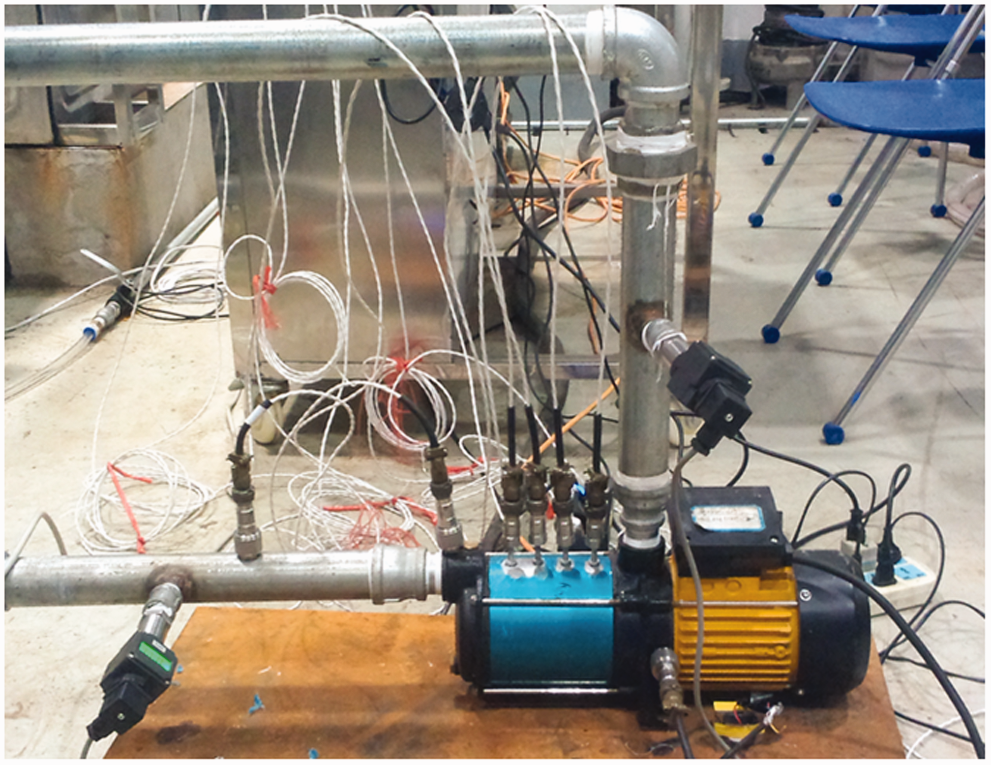
Test bench.
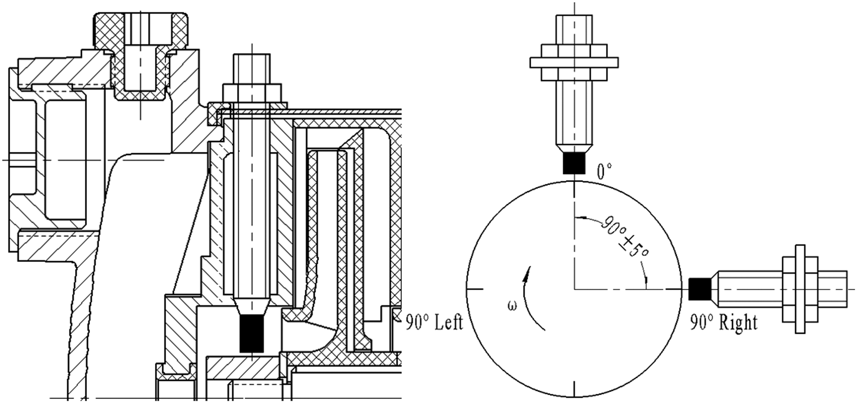
The installation mode of displacement sensor.
Axis locus under different operating conditions
The ADRE 408 vibration fault tester was used to measure the AL of the impeller lock nut under the two conditions of 0Qd and 1.0Qd. AL and corresponding time domain waveform diagrams under different working conditions are shown in Figure 17. Under the condition of 0Qd, the AL is unstable, the eccentricity is obvious, and the maximal and minimal RD are 100.9 µm and 53.4 µm, respectively. Under the condition of 1.0Qd, the AL is stable, there is also clipping, although the eccentricity is weak and the maximal and minimal RD are 93.8 µm and 64.6 µm instead. The whirl direction of the AL is positive precession and the phase characteristics are stable under both two conditions.
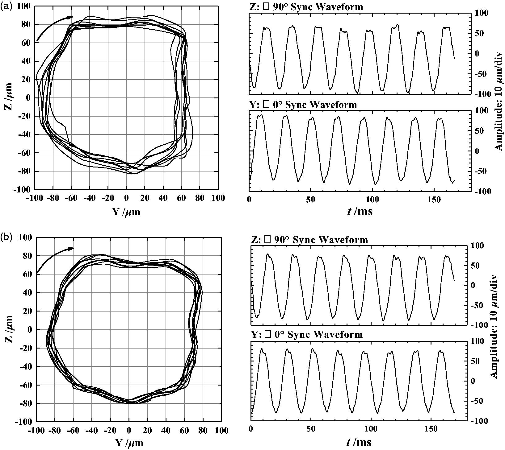
The axis locus under different operating conditions. (a) 0 Qd; (b) 1.0 Qd.
The time domain waveform of the AL has been transformed to obtain the spectrogram, as shown in Figure 18. The main frequency of the vibration signal is the axial frequency under different working conditions. The second frequency of the 0Qd is the blade passing frequency, and in the 1.0Qd is the multiplier of the axis frequency. Since the time-domain waveform diagram of the AL is not a simple sine wave, but a waveform diagram containing a plurality of frequency components. In addition to the fundamental frequency, it also includes the sub-frequency, the multiple frequency, and the blade passing frequency. Therefore, to analyze the fault features from the AL, it is necessary to filter the curves.
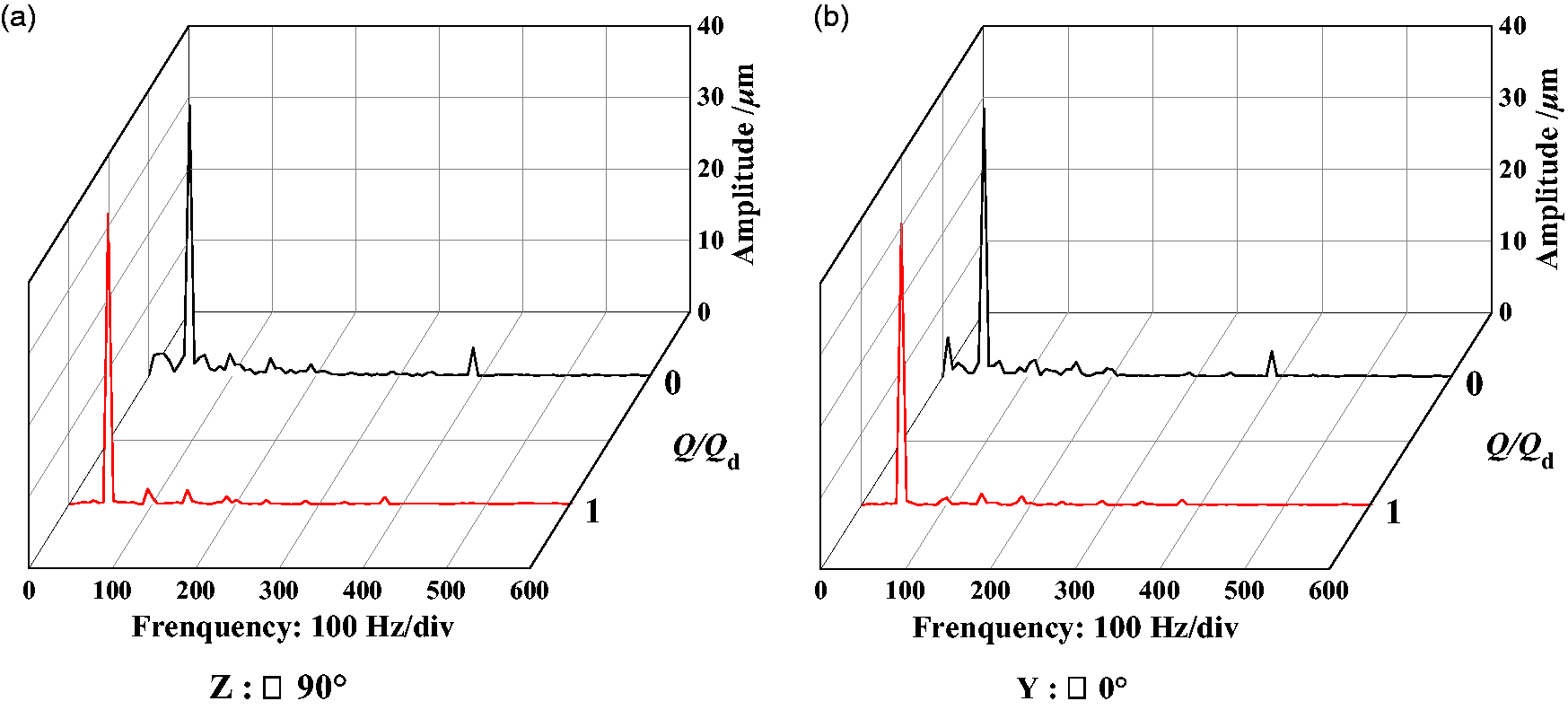
The frequency spectrum of displacement.
Filter analysis of axial locus
First, the AL of the axial frequency (i.e. the axial locus diagram of the power frequency) is obtained. As shown in Figure 19, the AL of the locus curves under the two working conditions is ellipse with little difference between the long and short axis, and the whirl directions is positive precession. The AL curves are insensitive to the change of flow rate, and the displacement of them varies little, indicating that the rotor component is eccentric and there exists unbalanced mass. Meanwhile, there is no significant difference in the bearing clearance or bearing stiffness in the direction. If there is a large difference, the AL should be in the shape of an ellipse with a large difference between the long and short axis. Therefore, the problem of bearing can be ruled out from the AL curve of axis frequency.
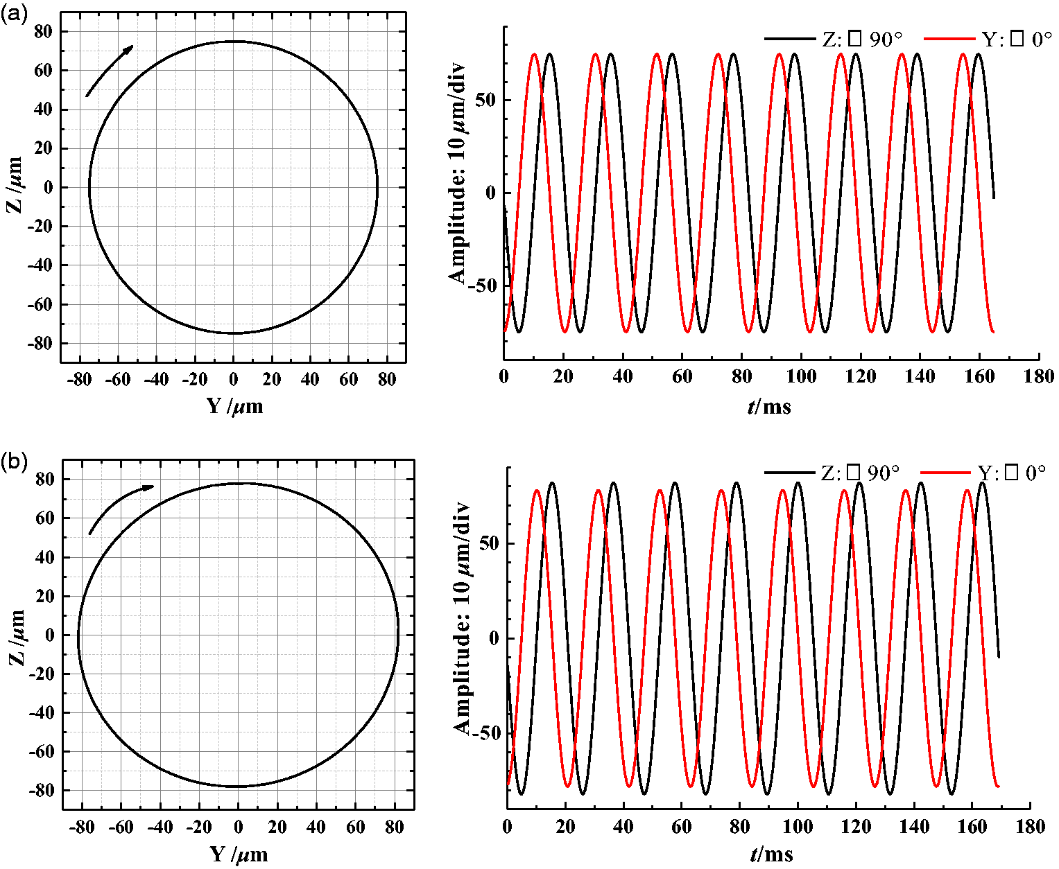
The AL of frequency-doubled under different working conditions is shown in Figure 20. The whirl directions are positive precession, and the locus curves are ellipse with large difference between long and short axis. These could be ascribed to the fact that the impeller has a certain misalignment when it is mounted on the shaft, which makes the AL of frequency-doubled a flat elliptical appearance. At the same time, the maximal RD increases with the increase of flow rate, since the misaligned rotor is sensitive to the change of flow rate, showing an enhancement in the misalignment signal as the flow rate increases. Therefore, the gap between the impeller hub and the shaft can be reduced.
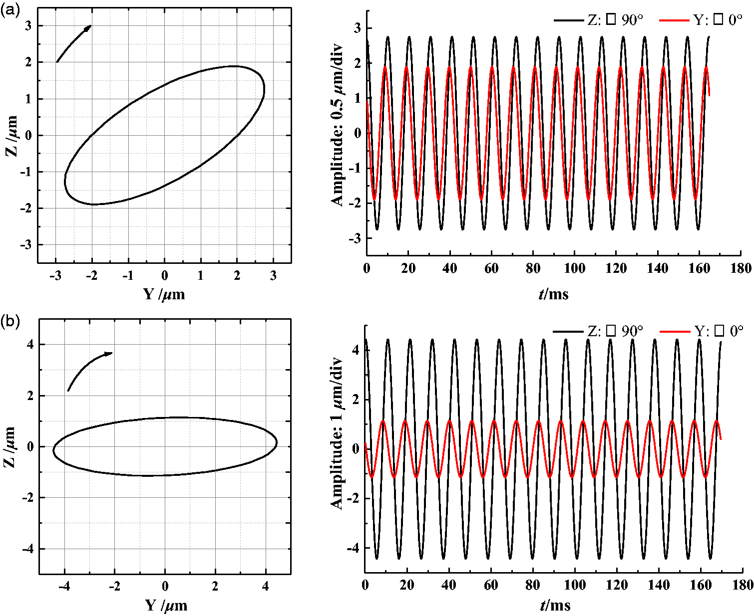
2X filtered orbit shaft.(a) 0 Qd; (b) 1.0 Qd.
Conclusion
The transient RD response, accelerate response and AL of the cantilever centrifugal pump under “dry state” and “wet state” are analyzed, respectively, based on SAMCEF, and the results show that the RD and acceleration amplitude at the pump body which is far away from the bearing are variable when the unbalance mass is loaded under dry state and increase with the distance away from the bearing. The RD and the amplitude of the acceleration at the impeller nut reach maximum. Meanwhile, the RD amplitude at the pump body increases as the unbalance mass increases. During the start-up time, the maximal RD at the locking nut increases with adding starting time.
Under the wet condition, the dynamic sealing force of the impeller can improve the stability of the rotor system of the multistage pump and effectively reduce the amplitude of the RD. Taking fluid excitation including the RF, AF and torque into consideration, the AL curves of the impeller are various when under different operating conditions. The AL curves are rather complex, but the magnitude of the maximal RD keeps the same level. When the mass of the fluid in the impeller is simplified to various additional mass, the maximal RD shows an exponential growth trend with the increase of the additional fluid mass. Therefore, the transient response analysis under wet state should take various factors into account, such as sealing force, fluid exciting force and fluid additional mass.
The experimental results show that the AL is changing under different working conditions. Under the 0Qd, the AL is unstable, and the eccentricity is the largest. Under 1.0Qd, the AL is stable and the eccentricity is weak. The AL curve of the 1x axial frequency is an ellipse with little difference between the long and short axes, and the shape of AL at the 2x axial frequency is an ellipse with large difference between the long and short axes, and it can be inferred that there is a misalignment and eccentricity in the multi-stage pump rotor system.
Footnotes
Declaration of conflicting interests
The author(s) declared no potential conflicts of interest with respect to the research, authorship, and/or publication of this article.
Funding
The author(s) disclosed receipt of the following financial support for the research, authorship, and/or publication of this article: This work was supported by National Key Research and Development Plan (grant no. 2017YFC0404204 and 2017YFC0403703), National Natural Science Foundation of China (grant no. 51609106), Key Research and Development Plan of Jiangsu Province (grant no. BE2017334), and Key Projects of Independent Innovation Funds in Agricultural Science and Technology in Jiangsu Province (grant no. CX (16) 1004).