
Abstract
Rolling mills vibration is a key factor that hinders the production of thin-strip steel. Currently, vibration is mainly suppressed by adjusting rolling mill parameters which is not a common approach. Due to special working conditions, the information of work roll, such as displacement and velocity, cannot be directly measured. Therefore, based on extended state observer, new resonance ratio control method, which is a common approach, is proposed to suppress the rolling mill vibration. First, the equivalent mass of the back roll is identified. Then, the interaction force between the work roll and the back roll and the velocity of the back roll are estimated using the extended state observer. Finally, these values are introduced into the input of the servo valve to compensate. The simulation results indicate that vibrations of both the work roll and the back roll are suppressed, and this method has a great tolerance for the identification error of the back-roll equivalent mass, and extended state observer compensation possesses a more superior vibration suppression than disturbance observer compensation.
Keywords
Introduction
Rolling mill vibration has become a bottleneck for manufacturing thin steel strips and a worldwide problem,1,2 as it can cause unacceptable thickness variations and severely damage the mill equipment.3,4 Therefore, damping mill vibration is very important for the rolling industry.
Rolling mill vibration is a coupling vibration among mechanical, electrical, hydraulic, and rolling interfacial subsystem. 5 Presently, vibration is mainly suppressed by adjusting rolling mill parameters by installing vibration dampers, 6 improving the quality of the grinding roll,7,8 changing the emulsion lubrication characteristics,9,10 or the tuning mechanical clearance, 11 which plays an important role in vibration damping. In addition, some researchers adopted heuristic algorithms, such as neural networks and genetic algorithms, to optimize the state parameters of rolling mills. 12 As a result, rolling chatter was decreased and rolling speed was increased. For the above-mentioned research, the rolling mill parameters changed include equivalent stiffness, equivalent damping, and excitation force.
With the development of control theory, active vibration suppression has attracted the attention of researchers. This method is general and does not distinguish vibration sources. Model-based nonlinear control techniques, energy considerations, and the theory of differential flatness were applied to address the so-called wrapper rolls and chatter vibration phenomena. 13 To address the vibration, a robust controller based on quantitative feedback theory was designed for the gauge control model. Compared with the proportion-integral-derivative (PID) controller, this model had better disturbance attenuation performance for parameter uncertainty and external disturbance. 14 Based on the principles of statistics and optimal control theory, Baoyu 15 proposed a stochastic optimal controller. The optimal control force was introduced between the work roll and the back roll, and the mean square value of work-roll vibrational acceleration was decreased drastically. Based on the dual target of improved particle swarm optimization, a vibration control method was suggested to optimize the control parameters of the hydraulic pressure down system, which effectively alleviated system vibration. 16
A control technique based on the disturbance observer, called resonance ratio control, was proposed for the two-inertia system. 17 By feeding back the torsional torque estimated by the disturbance observer, the virtual motor inertia moment can be changed to an arbitrary value, which means that the resonance frequency can be changed.18–20 Due to special working conditions, work roll parameters, such as displacement and velocity, cannot be directly measured. Therefore, the resonance ratio control can be used to suppress rolling mills vibration.
Resonance ratio control was proposed for the two-inertia non-stiff system. However, the dynamic of the hydraulic cylinder must be considered for the rolling mill vibration. The disturbance observer can only estimate the total disturbance; thus, it is not suitable for the rolling mill vibration. In this paper, based on extended state observer (ESO), new resonance ratio control is proposed. With the exception of the interaction force between the work roll and the back roll, the velocity of the back roll, which is estimated by ESO, is fed back. First, the equivalent mass of the back roll is identified using an orthogonal filter to remove the effect of parameter error from the total disturbance. Then, the interaction force between the work roll and the back roll and the velocity of the back roll, as estimated by ESO, is fed back to the servo valve. The effects of two compensator parameters, ESO bandwidth and compensation gain, on vibration suppression are analyzed. The simulation results indicate that the vibrations of both the work roll and the back roll are suppressed. This method has a great tolerance for error identification for the back-roll equivalent mass. What is more, the comparison between ESO compensation and disturbance observer (DOB) compensation shows that ESO compensation possesses a more superior vibration suppression.
Mathematic model of rolling mill vibration
Rolling mill vibration is a coupling vibration among mechanical, electrical, hydraulic, and rolling interfacial subsystem. Therefore, a mathematic model of rolling mill vibration should include mechanical, hydraulic, and electrical components, along with the rolling interface. However, the topic of this research is active vibration suppression, which is a universal method. As a result, the rolling interface component can be replaced by a dynamic rolling force.
The following simplifications are used: (1) only vertical vibration is considered; (2) the rolls are symmetric about the centerline of the mills; (3) the centerline is static; (4) the structure of the mill is considered a rigid body; (5) the upper back roll and cylinder body are assumed as a whole; and (6) the piston rod and mill structure are assumed as a whole.
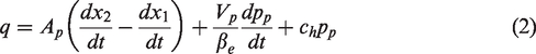
An MOOG-D661 electro-hydraulic servo valve, one outlet of which is blocked, is used. In rolling, this valve works near the zero position. Therefore, the flow-pressure equation can be linearized as

The hydraulic cylinder is differential. The servo valve can adjust the pressure of the piston side, but not the pressure of the rod side which can be assumed constant. The flow continuity equation applied to the piston side can be written as follows
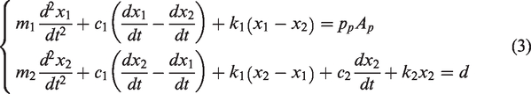
The lumped-mass model is suitable for our research. According to the above-mentioned assumptions, the mill structure, which includes the rack, rollers, and a hydraulic cylinder, is described as a 2-degree of freedom lumped-mass model. Because this research refers to vibration, only the dynamic portion of the parameter values is considered. According to vibration method, the kinetic equations of mill structure are written as follows
A schematic diagram of the coupling dynamic model, including the roll system, hydraulic servo system, and control system, is depicted in Figure 1.
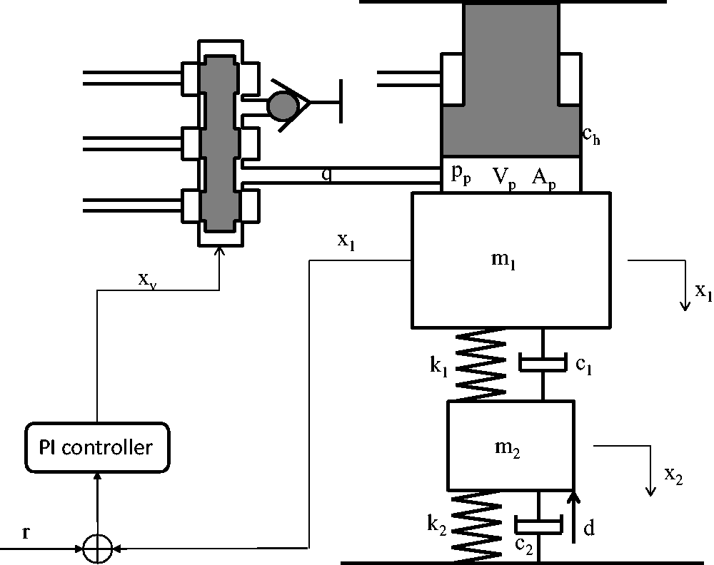
Schematic diagram of mill structure.
Problem description
Due to special working conditions, information on the work rolls, such as displacement and velocity, cannot be directly measured. The active vibration suppression controller is designed using only directly measurable information (the input of the servo valve, the pressure of hydraulic cylinder, and the displacement of back roll). A compensation signal produced by the active vibration suppression controller is added to the original input of the servo valve to suppress vibration of the work roll and the back roll.
Active vibration suppression
Parameter identification
To estimate the interaction force between the back roll and the work roll, the equivalent mass of the back roll must be identified. Note that this identification is done with external disturbance. An orthogonal filter is applied to remove the effect of parameter error from the total disturbance.
21
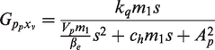
For the sake of writing, the interaction between the work roll and back roll is defined as
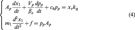
In equation (4), parameters
Design orthogonal filter

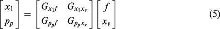
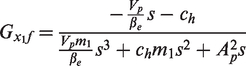
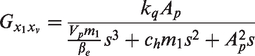
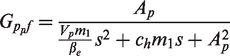
The signals from both the left side and the right side of equation (5) are introduced into the orthogonal filter. The following equation can be obtained

In equation (7), disturbance
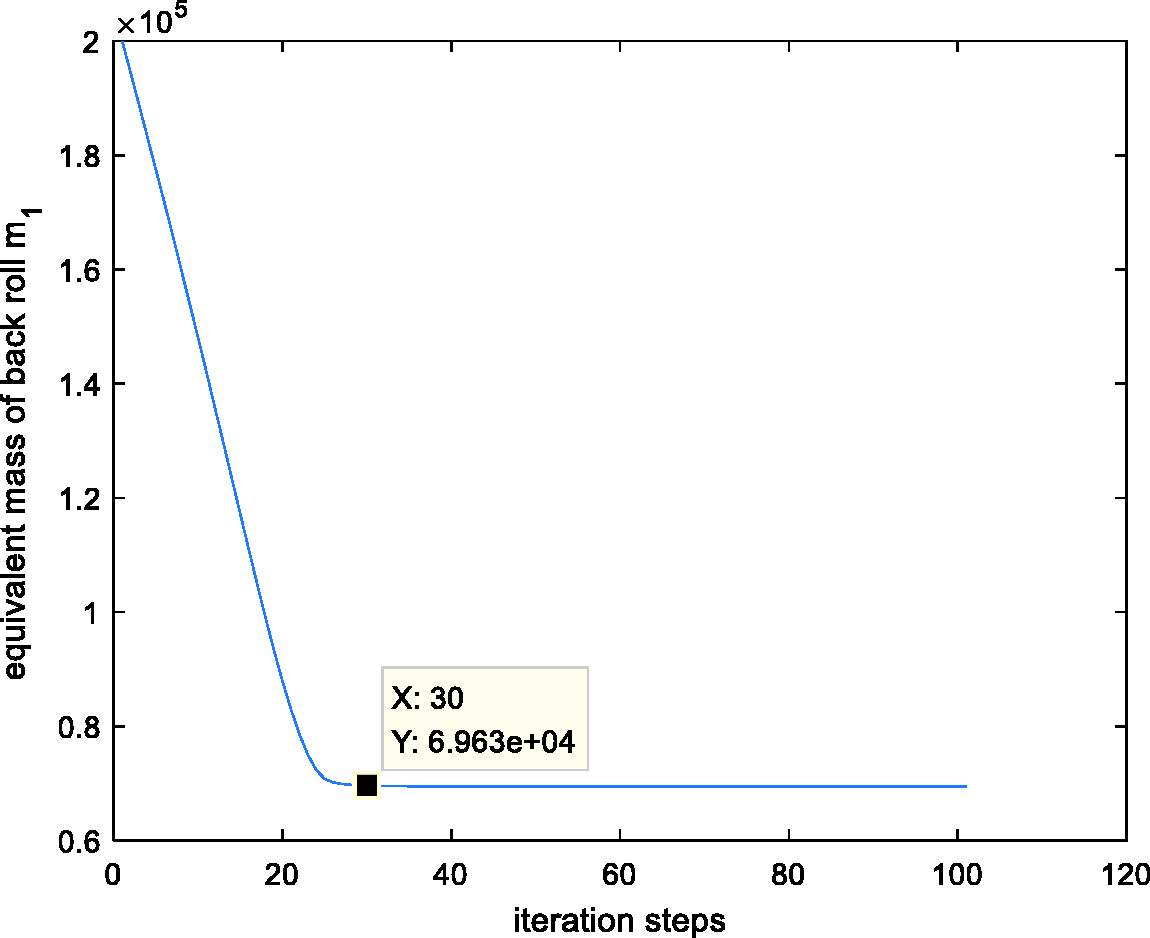
Identification of the equivalent mass of the back roll.
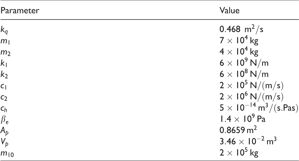
Simulation parameters.
From Figure 2, the equivalent mass of the back roll converges to 6.96 × 10⁴ kg when the number of iteration steps equals 30. The identification result is very close to the true value; error is only 0.57%.
Active vibration controller design
In this subsection, based on resonance ratio control, the active vibration controller is designed. From equations (1) to (3), the diagram of rolling mill vibration is shown in Figure 3(a).
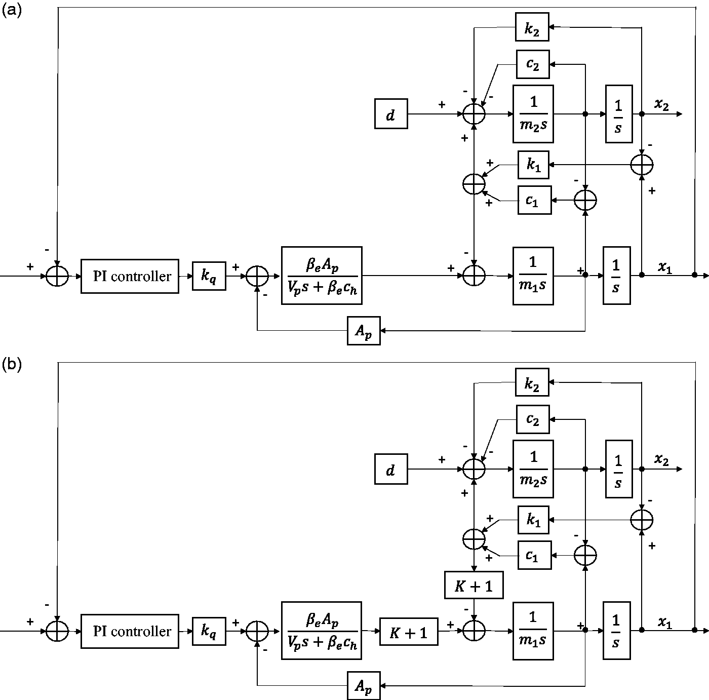
(a) Diagram of rolling mill vibration; (b) Equivalent diagram of resonance ratio control.
The nature of resonance ratio control is to change the virtual back roll mass, which means that the resonance frequency can be changed. We set the virtual back roll mass as

To achieve compensation, the interaction force between the work roll and the back roll and the vibration velocity of back roll should be obtained. Next, the estimation of interaction force and vibration velocity via ESO will be shown.
By defining the state variable 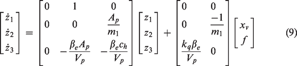
From equation (9), disturbance 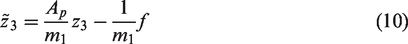
By substituting equations (10) into (9), a state space in the form of series integrals can be obtained

By defining 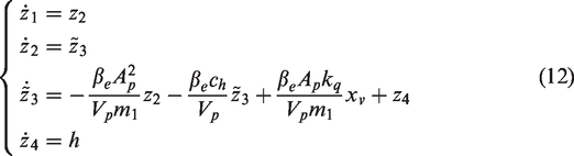
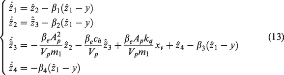
The nature of ESO is state observer. Compared with the state observer, the improvement of ESO is the extended state. ESO treats the internal disturbance and the external disturbance as the total disturbance which is treated as the extended state. The total disturbance and system states can be estimated in real time from its input–output data. ESO estimation is a dynamic process, and the estimation error is decreased by means of error feedback. When
When the estimation of 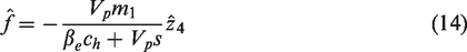
Now, the vibration velocity of the back roll,
Equivalent diagram of resonance ratio control with ESO.
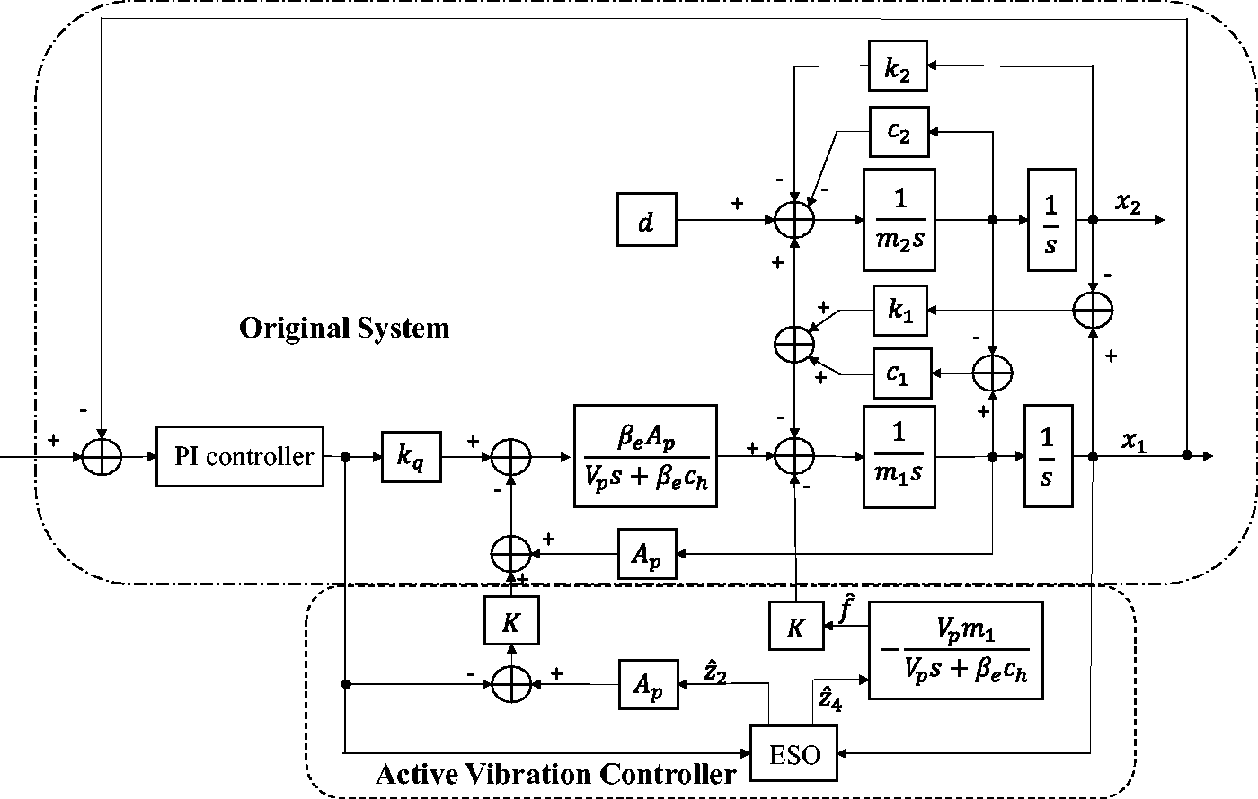
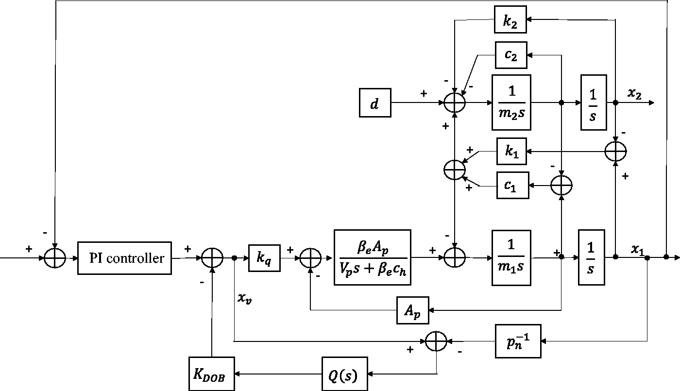
In Figure 4, feedback position is not implemented physically. The position should be moved to the servo valve input. According to control theory, the feedback gain of back-roll vibration velocity is equal to
Active vibration suppression diagram.
Active vibration controller parameters analysis
The performance of the vibration suppression controller depends on the active vibration controller parameters. Therefore, it is very important to analyze their effect on vibration suppression. The active vibration controller includes five parameters: ESO gains
For rolling-mill vibration suppression, the ability of the work roll to resist dynamic rolling force
With
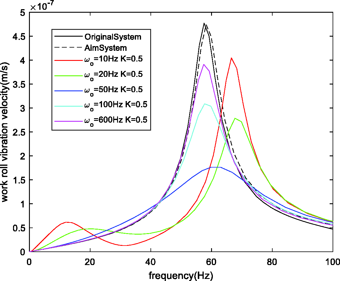
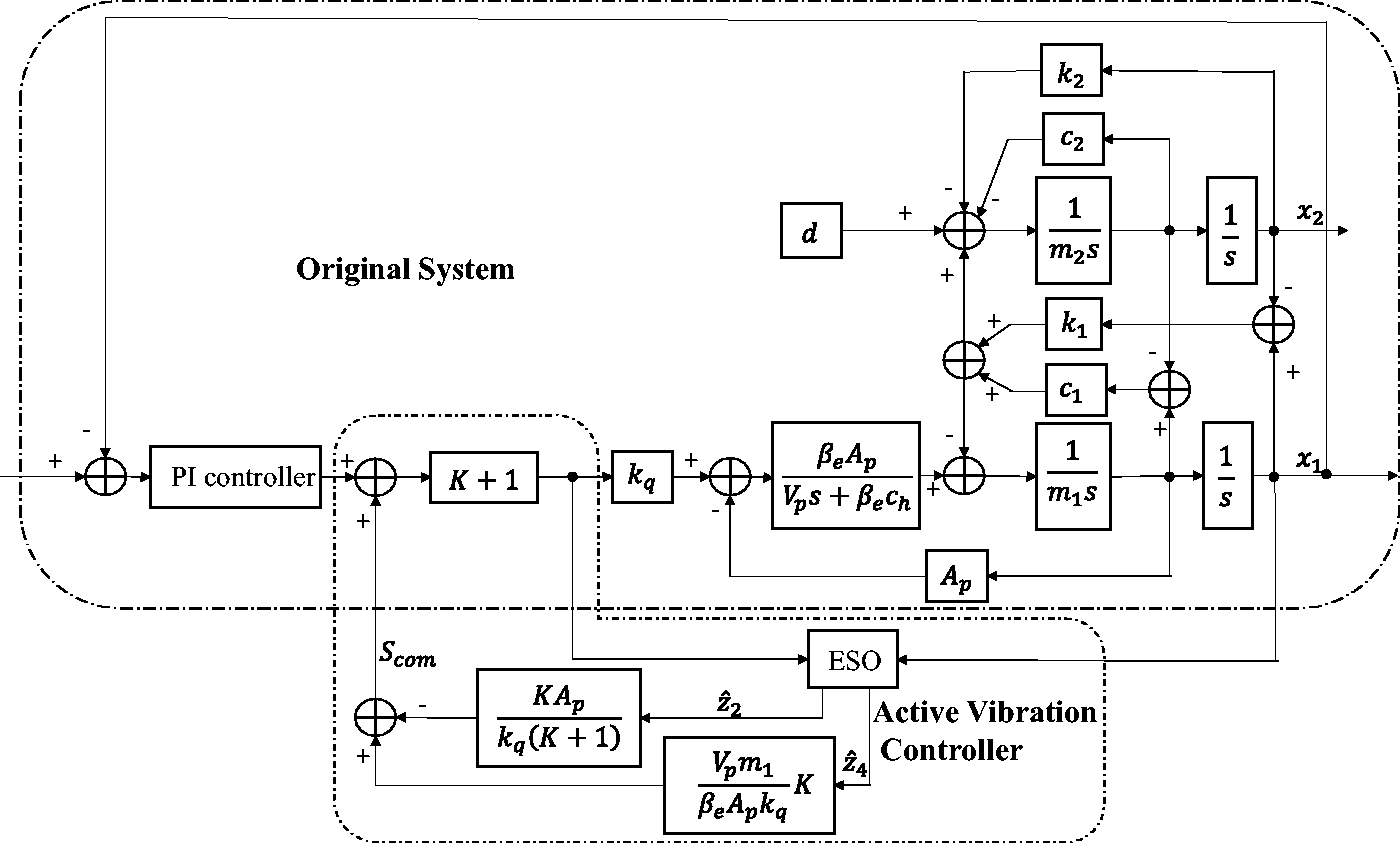
Amplitude-frequency plots with varied ESO bandwidth.
From Figure 6, the effect of ESO bandwidth is nonlinear. The dynamic response gradually approaches the aim system as ESO bandwidth increases. Moreover, ESO bandwidth that is too large or too small deteriorate the dynamic response means that there is an optimal ESO bandwidth for each compensation gain. We can conclude that, for vibration suppression, the response speed is not too fast or too slow.
Similarly, for
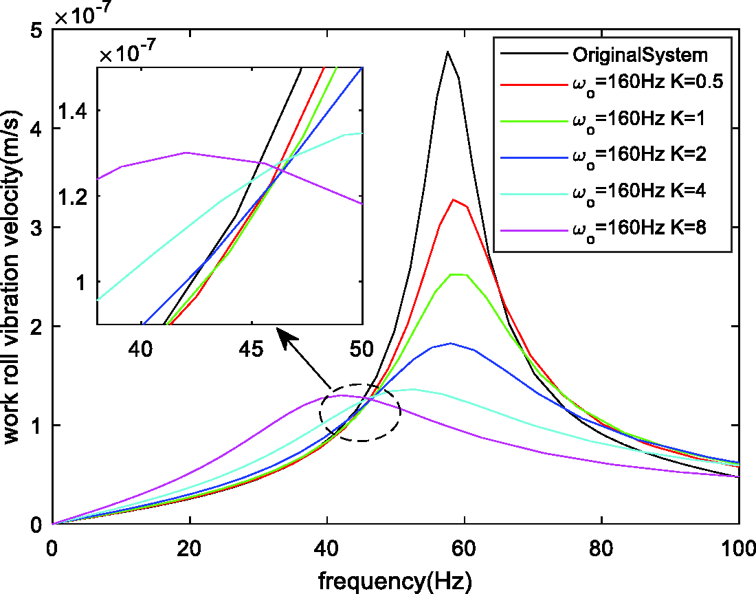
Amplitude-frequency plots of the work roll with varied compensation gain.
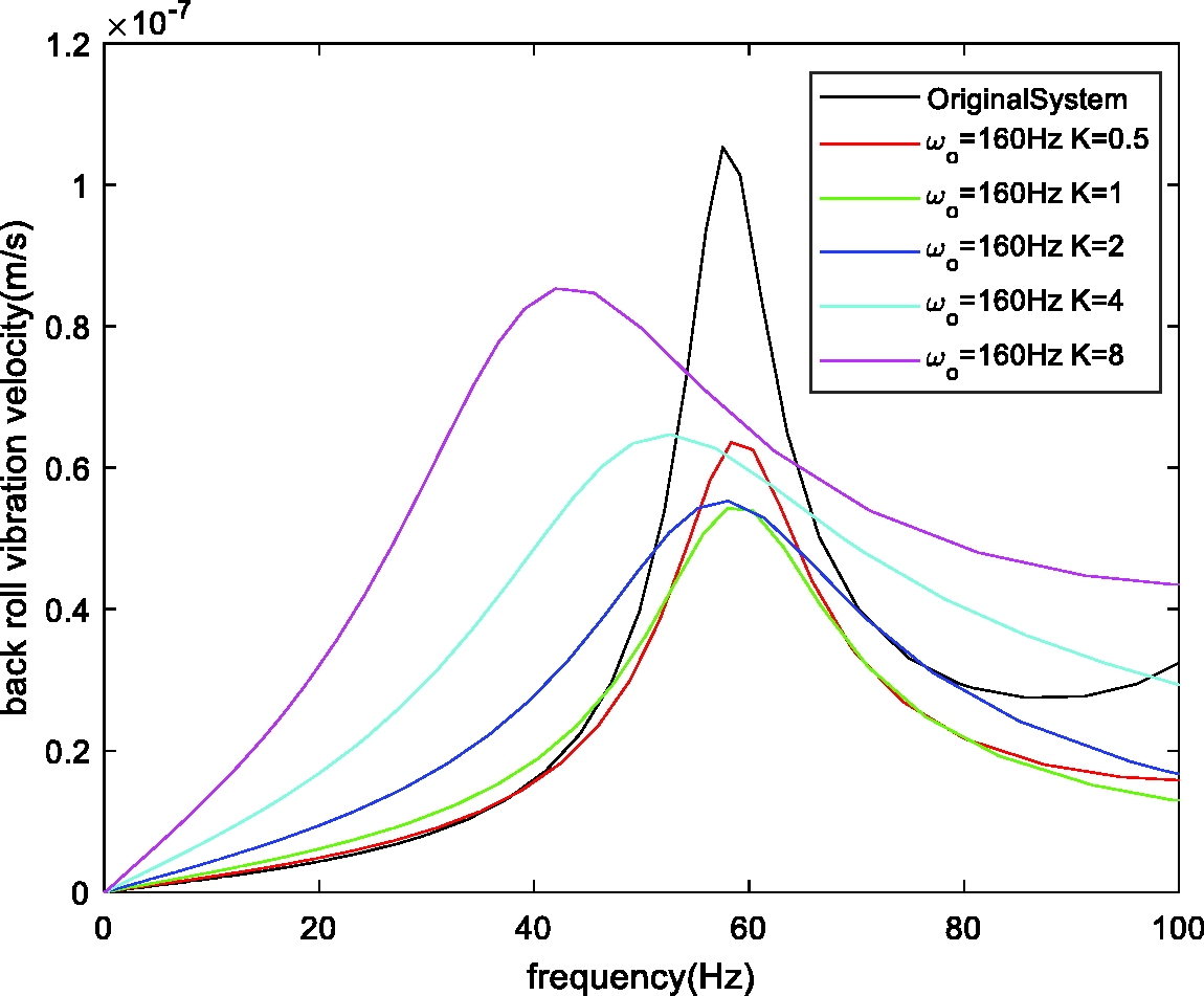
Amplitude-frequency plots of back roll with varied compensation gain.
From Figure 7, it can be seen that, with increasing compensation gain, the amplitude is more attenuated at the resonance frequency and increased at the low-frequency range. Moreover, the crossing points of the amplitude-frequency plots with varied compensation gain are all near 45 Hz, which means that they have little to do with compensation gain. Hence, if compensation gain can be selected, such that this crossing point is near the local maximum, vibration suppression of the work roll can be more effective.
From Figure 8, the effect of compensation gain on back roll vibration is nonlinear. The dynamic response of the back roll initially improves and then deteriorates. Therefore, the compensation gain cannot be too large due to the limit of back roll vibration.
In the case where
Numerical simulation
In rolling, there are two types of vibration that occur frequently: single dominant frequency and multiple dominant frequency. As a result, the two types of dynamic rolling force with single and multiple dominant frequencies are used to show the vibration suppression performance. The system parameters are set as shown in Table 1. The ESO bandwidth is set at
Vibration suppression for single dominant frequency
For a single dominant frequency, the dynamic rolling force is set at 60 Hz and 1 × 10⁴ N. Compared with cases without compensation, the work roll vibration and the back roll vibration with compensation are depicted in Figures 9 and 10, respectively.
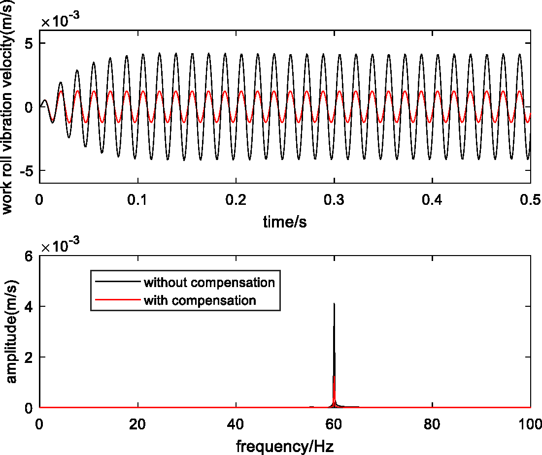
Comparison of work roll vibration for a single dominant frequency.
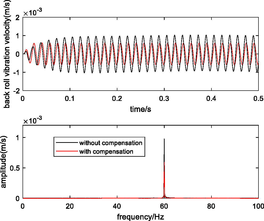
Comparison of back roll vibration for a single dominant frequency.
From Figure 9, the amplitude without compensation is 4.11 mm/s, and the amplitude with compensation is 1.23 mm/s. The vibration of the work roll is decreased by 70%. From Figure 10, the amplitude without compensation is 0.94 mm/s, and the amplitude with compensation is 0.59 mm/s. The vibration of the back roll is decreased by 37%.
The comparison between the actual values and the estimated values of the three state variables
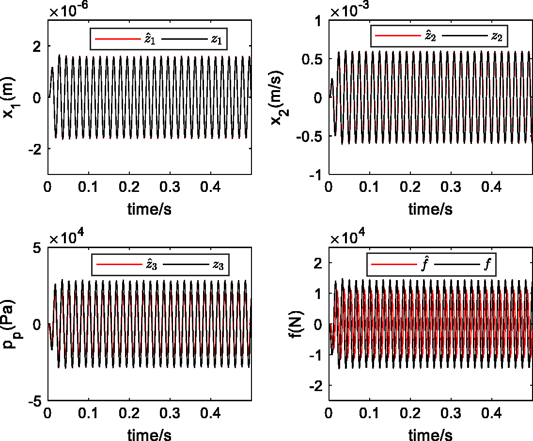
Comparison between the actual value and estimated value for a single dominant frequency.
Vibration suppression for multiple dominant frequencies
For multiple dominant frequencies, the dynamic rolling force is defined as the sum of (55 Hz, 1 × 10⁴ N), (60 Hz, 1 × 10⁴ N), and (65 Hz, 1 × 10⁴ N). Compared with a case without compensation, the work roll vibration and the back roll vibration with compensation are depicted in Figures 12 and 13, respectively.
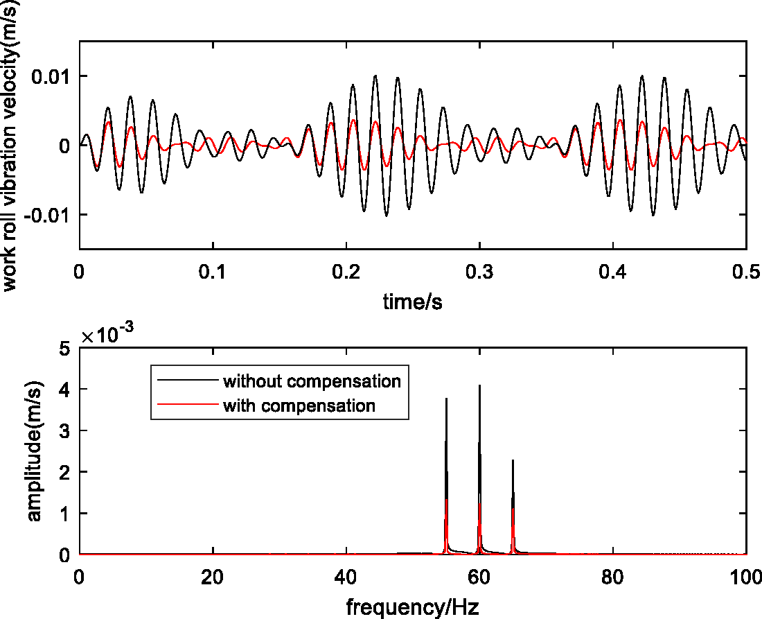
Comparison of work roll vibration for multiple dominant frequencies.
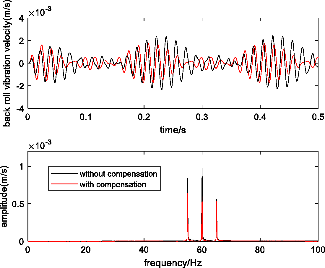
Comparison of back roll vibration for multiple dominant frequencies.
From Figure 12, the amplitudes of 55, 60, and 65 Hz without compensation are 3.77, 4.08, and 2.28 mm/s, respectively. The virtual value of work roll vibration without compensation is 4.3 mm/s. The amplitudes of 55, 60, and 65 Hz with compensation are 1.33, 1.23, and 1.1 mm/s, respectively. The virtual value of work roll vibration with compensation is 1.5 mm/s. The virtual value of work roll vibration decreased by 65.1%. From Figure 13, the amplitudes of 55, 60, and 65 Hz without compensation are 0.81, 0.93, and 0.56 mm/s, respectively. The virtual value of back roll vibration without compensation is 0.96 mm/s. The amplitudes of 55, 60, and 65 Hz with compensation are 0.64, 0.59, and 0.53 mm/s, respectively. The virtual value of back roll vibration with compensation is 0.73 mm/s. The virtual value of back roll vibration is decreased by 20%.
The comparison between the actual values and the estimated values of the three state variables
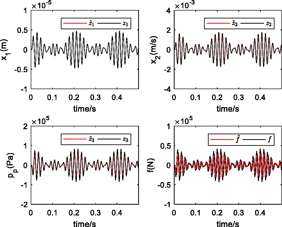
Comparison between the actual value and the estimated value for multiple dominant frequencies.
Effect of parameter identification error on vibration suppression
As mentioned above, the equivalent mass of the back roll must be identified to estimate the interaction force between the back roll and the work roll. However, the identification result is idealized. In reality, identification error always exists. It is necessary to analyze the effect of parameter identification error on vibration suppression.
Assume that the identified equivalent mass of the back roll is equal to 9 × 10⁴ kg and 5 × 10⁴ kg. The identification error is −28.6 and 28.6%, respectively. Other parameters are the same as the above-mentioned. For varied identification results, the amplitude-frequency plots of the work-roll vibration velocity are depicted in Figure 15. From Figure 15, the identification error of the back-roll equivalent mass does not cause a significant change in the work-roll vibration suppression performance. Thus, this method has a great tolerance for the identification error of the back-roll equivalent mass.
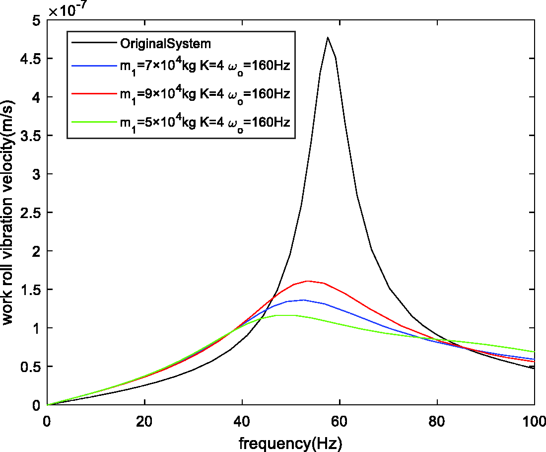
The amplitude-frequency plots of work roll vibration velocity with identification error.
Compared with DOB method
Disturbance observer method
18
is used to compare with the proposed method. From equation (4), the nominal transfer function 
According to DOB method, the total disturbance can be obtained by

To make the comparison more meaningful, the same low-pass filter bandwidth and compensation gain are chosen, i.e.
Configuration of DOB.
The comparison result between DOB compensation and ESO compensation is shown in Figure 17. From Figure 17, the work roll vibration of ESO and DOB compensation is basically the same, and the back roll vibration of ESO compensation is smaller than that of DOB compensation. ESO compensation can apply the back-roll vibration velocity and the total disturbance to suppress vibration. However, DOB compensation can only apply the total disturbance to suppress vibration. Due to the use of more information, the vibration suppression of ESO compensation is superior to DOB compensation.
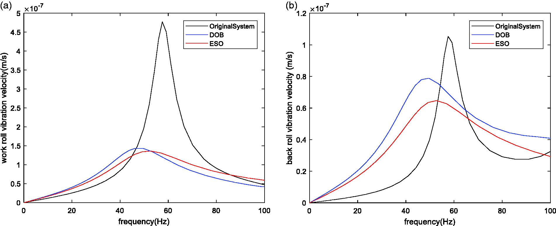
Comparison result between DOB compensation and ESO compensation: (a) work roll vibration; (b) back roll vibration.
Conclusion
Based on state estimation and parameter identification, an active vibration suppression controller to suppress rolling mill vibration is proposed. Through the parameter analysis and the numerical simulation, these conclusions can be obtained as follows:
The ESO bandwidth that is too large or too small deteriorates the dynamic response, and there is an optimal ESO bandwidth for each compensation gain; The compensation gain can be selected, such that the crossing point is near the local maximum and cannot be too large due to the limit of the back roll vibration; For the single dominant frequency (60 Hz), the vibration of the work roll is decreased by 70%, and the vibration of the back roll is decreased by 37%; For multiple dominant frequencies (55, 60, and 65 Hz), the work roll vibration is decreased by 65.1%, and the back roll vibration is decreased by 20%; This method has a great tolerance for the identification error of the back-roll equivalent mass; The comparison between ESO compensation and DOB compensation shows that ESO compensation possesses a more superior vibration suppression.
Footnotes
Declaration of conflicting interests
The author(s) declared no potential conflicts of interest with respect to the research, authorship, and/or publication of this article.
Funding
The author(s) received no financial support for the research authorship, and/or publication of this article.