
Abstract
The maximum wind load direction of tower crane is considered to be perpendicular to its jib. The interference effects of its different segments and across-wind loads are ignored in traditional crane safety evaluation. This study proposes a general scheme for the safety evaluation of tower cranes under fluctuating wind loads. The wind coefficients of a full-scale model of a tower crane were calculated by computational fluid dynamics, and then the time history of wind loads, simulated through the autoregressive method, were applied to the finite element model of a tower crane. The results reveal that the maximum along-wind load direction deflected 30°–60°, and the mean ratio of the absolute value of the across-wind coefficient to the along-wind coefficient of the tower crane was 8.56%, which indicated that the across-wind loads should be taken into account in wind-resistant design. Comparing the wind-induced responses of four typical wind directions, the maximum displacement, the bending stress and the axial stress of the tower crane occurred in the positive direction. Furthermore, the maximum acceleration of the cat-head was 0.028 m/s2, which met the comfort requirements of the operator. Although the tower crane met the strength and static stiffness requirements of design rules, the maximum bending stress at the junctions between the jib and the slewing platform, the counterweight and the counter-jib, exceeded the allowable stress, and the first modal of the tower crane was excited. These results warrant considering the effect of fluctuating wind loads in the safety evaluation of a tower crane.
Introduction
Tower cranes are widely used in the fields of industrial and civil construction due to their superior properties such as wide adaptation range, large turning radius, and lifting height. The flexibility, thinness, length, and height of tower crane make it more sensitive to wind loads and more prone to wind-induced disasters. Thus, it is imperative to study the wind-induced responses of tower cranes to ensure their safe operation.
In the applicable design rules for tower cranes,1–3 the consideration of wind loads as static loads has been widely applied in engineering. Taking fluctuating wind loads into consideration, Ma et al. adopted the harmonic superposition method and autoregressive model (AR model) to simulate the time history of wind loads; the wind-induced dynamic response of a typical tower crane was obtained by applying the wind loads to the finite element model (FEM) of it, and the results showed that the displacement responses are stable under wind-induced vibration. 4 Fu et al. applied the Davenport power spectrum of fluctuating wind velocity and the AR method to obtain the responses of the tower crane, which would be unsafe if the fluctuating wind load was not considered. 5 Jiang and Li obtained the dynamic responses of displacement and acceleration by applying the Davenport wind velocity spectrum to the FEM of a tower crane, where a sharp fluctuation appeared in low frequencies. 6 The Kaimal wind velocity spectrum was applied to simulate the time history of wind loads, the nonlinear buffeting response of a tower crane was modelled by Sun, and the safety and serviceability of the tower crane was assessed. 7
The above analyses consider the direction of the maximum wind load of a tower crane to be perpendicular to its jib. However, the structure of a tower crane is similar to that of a container crane, for which the direction of the maximum wind load occurs at an angle deflected in the positive direction.8,9 Thus, it is meaningful to investigate the wind load characteristics of a tower crane, which can provide further information for the safety of tower cranes under wind-induced responses.
The most direct and effective method to obtain the wind-induced responses of a structure is via field measurements,10–12 but external environment variables cannot be fully controlled at the operation site, and the testing cost is high. The wind tunnel test, which is applied to study wind loads of tower cranes, is a well-developed method. Empirical methods were described by Eden et al. to obtain the wind force and moment of two shapes of crane jibs in the wind tunnel test. 13 The dynamic overturning moment of the tower crane was measured in the boundary layer wind tunnel by Voisin et al.; the inertial and centrifugal moments were much smaller than those of gravity and wind. 14
To analyse the air flow around the structure and evaluate the aerodynamic force, CFD is conducted as an economic and effective method to precisely define wind load characteristics.15,16 CFD analysis can be carried out through the Reynolds-Averaged Navier-Stokes (RANS) equation, the Large Eddy Simulation (LES), the Detached-Eddy Simulation (DES) and so on. LES is an unsteady turbulence-modelling approach, in which large eddies of turbulence are resolved explicitly, and small eddies are calculated by subgrid-scale models. The capabilities of LES for the calculation of blunt body flow are potentially superior to those of RANS.17,18 However, LES requires a fine grid inside the attached boundary layer to capture the small turbulent structures near the walls, which dramatically increases the computational cost. On the other hand, LES and RANS provide closer results for calculating the mean velocity and shear stress of wind flow over a blunt body. 19 DES is an increasingly popular hybrid RANS/LES technique capable of predicting massively separated flows, while RANS and DES turbulence models show little difference in the averaged forces and moments of a blunt body. 20 RANS is accomplished by time averaging the governing Navier-Stokes equations. With this method, distinct average quantities can be discerned in turbulent flow, which offers huge computational savings over both DNS and LES. 21 Therefore, RANS is applied to calculate the average wind coefficient of the structure in this study. Yang et al. obtained the wind coefficient of an angled steel triangular transmission tower under different wind directions through RANS; the results were essentially in agreement with the wind tunnel test values, and the maximum relative deviation was not higher than 7%. 22 The wind coefficients of different specifications of a standard section of a lattice tower were obtained by RANS by Xie et al., and the results were close to those of AIJ-RLB-2004. 23 Huang et al. proposed a CFD numerical approach based on RANS to estimate the wind coefficient of a container crane. The method was verified by comparing the results with those of the wind tunnel test. 24
The aforementioned analyses are based on the wind coefficient, which means that an accurate wind coefficient is an important component in calculating wind loads. Typically, the interference effects of different segments of the transmission tower, towering derrick and communication tower in the height direction are relatively small, meaning that the wind tunnel test can be carried out on different segments to obtain the respective wind coefficients.25–29 However, the tower crane has a larger extension structure, and the slewing platform, counterweight and cat-head have considerable influence on the nearby structures. If the wind coefficient of each partition is obtained, respectively, it will cause deviations in dynamic responses. A feasible method is to use the CFD technology to set up a full-scale model of the tower crane and then obtain the wind coefficient of each partition.
In this study, the full-scale model of a tower crane was established to obtain the integral wind coefficient and the local wind coefficient of its different partitions by CFD technology in the next two sections. Next, the time history of the wind load, which was generated by an AR model, was applied to the FEM of the tower crane in sections ‘Simulation of the stochastic wind field’ and ‘FE modelling and modal analysis’. Then the displacement, acceleration and axial stress, and bending stress of the tower crane were estimated to evaluate the safety of the tower crane. The final section concludes the study.
Tower crane description
A tower crane is composed of a counter-jib, jib, cat-head, mast and slewing platform, as well as subsidiary structures. These structures are made up of tube, angle steel, channel and square steel with different specifications. The steel is welded together with various profiles, which results in the complex surface details of the tower crane. The computing cost is prohibitively higher when considering all structural features, so it is necessary to simplify the characteristics within reason. The members with small windward areas, such as ladders in the middle of the tower mast and fences around the counter-jib that are made up of slender tubes, are removed.
The wind load of different spatial positions of tower crane is not always the same. The tower crane can be divided into 35 partitions along its height and length. Figure 1 shows the simplified model and partitions of the tower crane. H = 55 m and D = 80 m are the height and length of the tower crane, respectively. The anchorage device is the braced connection between the tower crane and the ground, for which the impact of wind loads on the tower crane are not considered.
Simplified model and partitions of QTZ125 tower crane.
CFD simulation
Airflow over the tower crane in the atmospheric boundary layer is modelled as incompressible and isothermal using the steady RANS equations. In this regard, the turbulence model is a key point in the applications of RANS. To address this issue, the Realizable
Grid generation and computational algorithm
Computational domain
The computational domain was designed as a prism. The wind loads of the tower crane under different wind directions can be achieved by changing the positions of the inlet and outlet. The volume of the computational domain is large enough to minimize its effects on the flow field of the tower crane model. The blockage ratio is less than 3%, which complies with the requirement of the wind tunnel test. Figure 2 shows the computational domain.
Computational domain of the model.
Grids
A hybrid grid method with hexahedral and tetrahedral grid was adopted in the numerical simulation. The computational domain was subdivided into internal and external domains, which were connected by pyramid grids. In the internal domain, the surfaces of the tower crane were meshed by triangle grids, and their adjacent regions were meshed by tetrahedral grids. The external domain was meshed using hexahedral grids, reducing computational cost. Grids in the computational domain were adjusted by preliminary calculation results. The initial grid number was 20 million, and then the thickness of the first layer of the boundary layer and the grid growth rate were modified based on the y+ value (the values of y+ of the grids were mostly between 30 and 100) and grid independence. Finally, the total number of grids is 30 million. The height of the first boundary layer is 1.8 mm, and the mean size of the triangular grid of the tower crane is 30 mm. Figure 3 shows the final grids of the domain.
Grids in the computational domain.
Boundary conditions
The computational domain contained an inlet surface and an outlet surface, which varied corresponding to different wind directions. The outlet surface was defined as free outflow. The inlet surface was applied for the velocity inlet, which was defined for terrain category B with the mean wind velocity, turbulent kinetic energy and turbulent dissipation rate32,33


A non-slip wall was applied for the ground and tower crane, the near wall was adopted by the non-equilibrium wall function and the remaining surfaces were set as symmetry. The accurate simulation of flow characteristics is the foundation for obtaining the correct wind loads of the tower crane. The mean wind velocity and turbulence intensity of the inlet (position 1) and 10 m ahead of the tower crane (position 2) in 0° wind direction along the height were compared with the theoretical data. It can be seen that the numerical simulation of normalized velocity and turbulence intensity are consistent with the theoretical data in Figure 4. The flow field can maintain the neutral equilibrium atmospheric boundary layer.
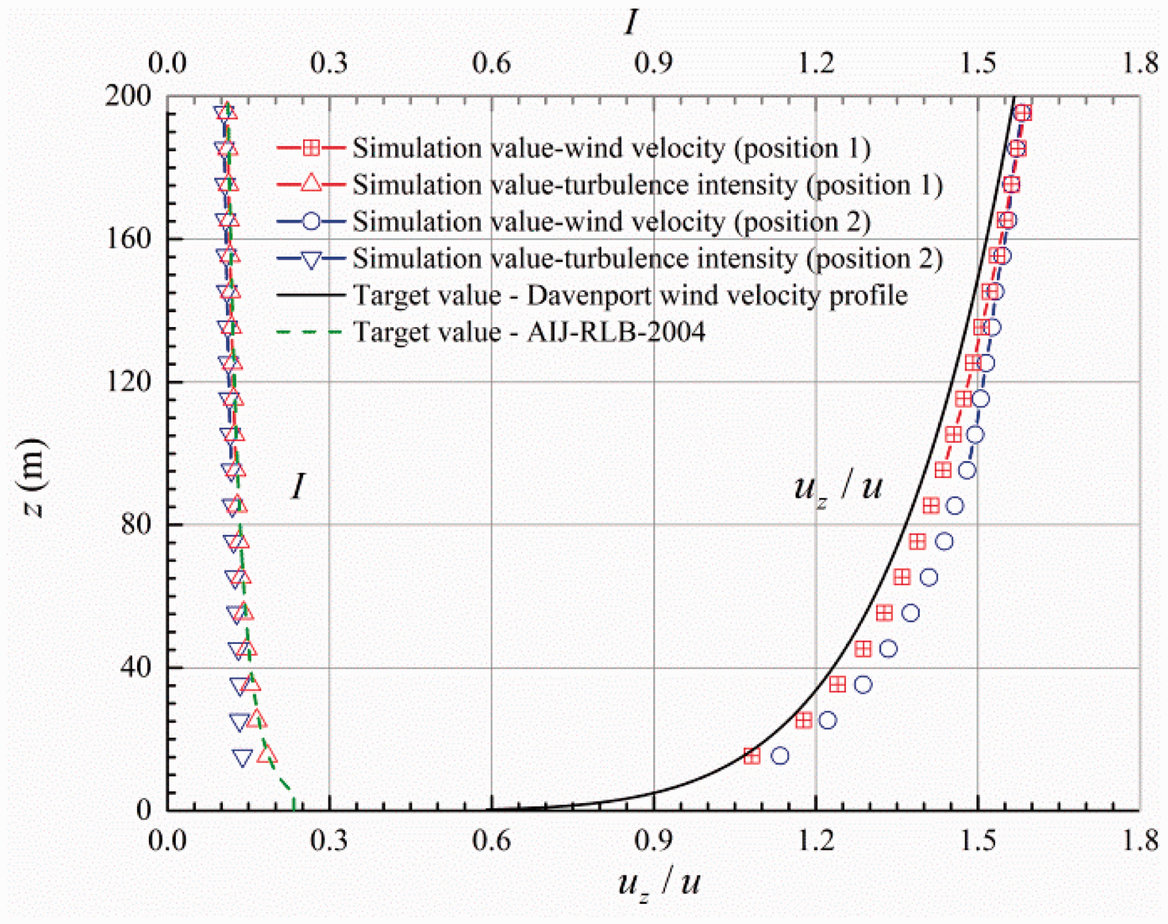
Target and simulation value of mean wind velocity and turbulence intensity.
Discrete method
The SIMPLE algorithm was used to solve the pressure–velocity coupling equation. To obtain the characteristics of flow field faster and more stably, the first-order upwind was applied for the spatial discretization of the Realizable
Wind coefficient
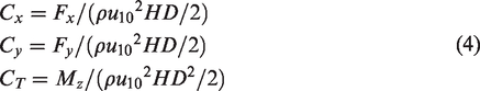
The wind coefficient is the dimensionless coefficient of wind load. The along-wind coefficient
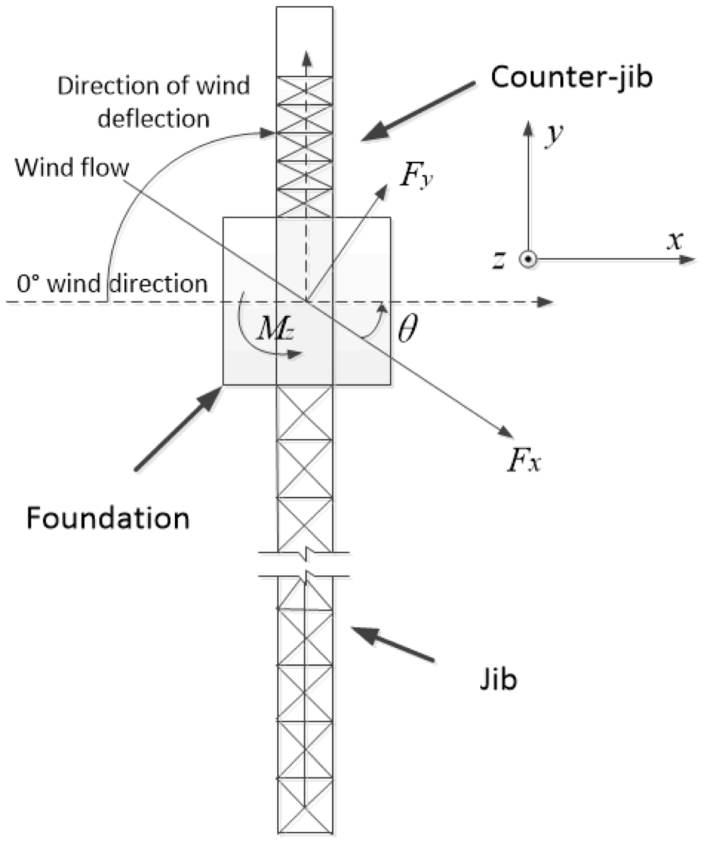
Wind direction and wind loads of tower crane.
The wind coefficient of the along-wind and across-wind of the tower crane in different wind directions and the ratio of the absolute value of the wind coefficient of across-wind to along-wind are shown in Figure 6. The maximum along-wind coefficient does not appear in the 0° or 180° wind directions but deflects 30°–60°. This result occurs because the shielding effect of the windward component on the leeward side is gradually weakened with the deflection of the wind direction. It is possible to miss the most unfavourable wind load direction for the safety analysis of the tower crane at the 0° wind direction, which is recommended for many design standards. The direction of the across-wind load is always perpendicular to the along-wind load direction, and the along-wind load always follows the wind direction; however, the angle between the across-wind load direction and the along-wind load direction varies in 90° or 270°. Furthermore, the maximum ratio of the wind coefficients of the across-wind to those of the along-wind reaches 17.9%, and the mean ratio is 8.56%. Therefore, it may be unsafe to neglect the across-wind loads of the tower crane. With the deflection of the wind direction, the torsion value of the tower crane gradually decreases. The torsion value is smallest when the wind direction is parallel to the jib with the minimum along-wind and across-wind loads.
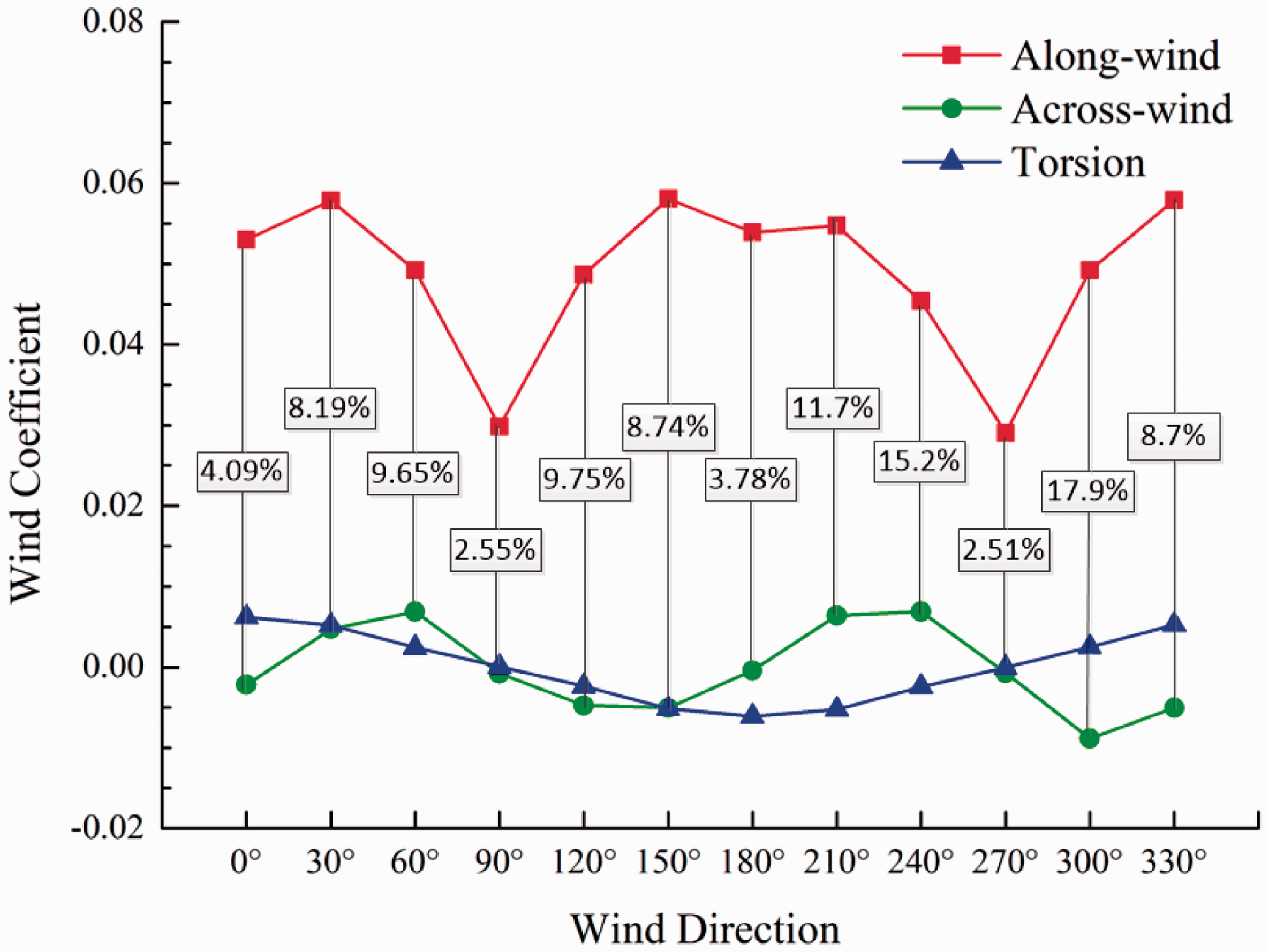
Wind coefficient of the tower crane in different wind directions.
Based on equations (1) and (4), the wind coefficient of the along-wind
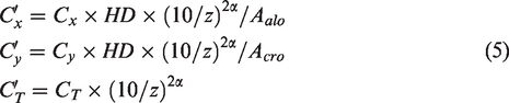
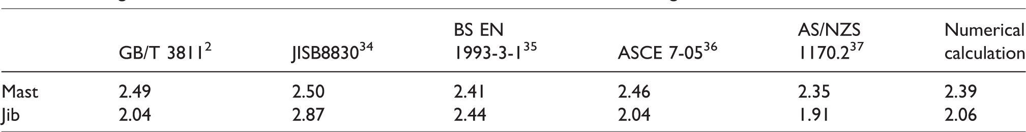
The numerical calculation of the along-wind coefficient involves the wind pressure height coefficient
Along-wind coefficients of numerical calculation and values of different design standards.
Simulation of the stochastic wind field
PSD of fluctuating wind velocity
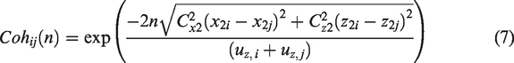
Fluctuating wind, which is the dynamic part of wind, causes a structure to generate random vibrations. The power spectrum density (PSD) completely describes the frequency contents and energy properties of the fluctuating wind, and the spatial correlation of fluctuating wind can be reflected in a coherent function. These parameters encompass the characteristics of fluctuating wind simulation.
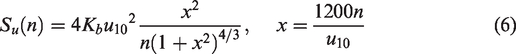
The fluctuating wind can be considered as a stationary Gauss stochastic process with a zero-mean value. The Davenport spectrum is used to describe the power spectrum of fluctuating along-wind velocity
38

Fluctuating wind velocity verification
The wind velocity at each position in space can be divided into the mean wind velocity that does not change with time and a fluctuating wind velocity with a zero-mean value. It is assumed that the fluctuating wind velocity at each position is a series of spatially related stationary stochastic processes. The AR model has the characteristics of short calculation time, high efficiency and high reliability, which are widely used in the time history simulation of fluctuating wind velocity. 40 The AR model passes a random series of white noises with zero-mean values through a linear filter and outputs a stationary stochastic process with specified spectral features. The parameters of the AR model are as follows: sampling points are 2048, autoregressive order number is 4 and time span is 204.8 s. Based on the height of the partition centre of the tower crane, the time history of the fluctuating wind velocity of 35 positions was established. According to the requirements of the wind-resistant design of the tower crane in working conditions, the mean wind velocity of 10 m is 13.3 m/s.
Figure 7 shows the target and simulated PSD of the fluctuating velocity of along-wind. The PSD of the fluctuating wind velocity and the target shows a good fit, which illustrates the accuracy of the numerical simulation of fluctuating wind velocity.
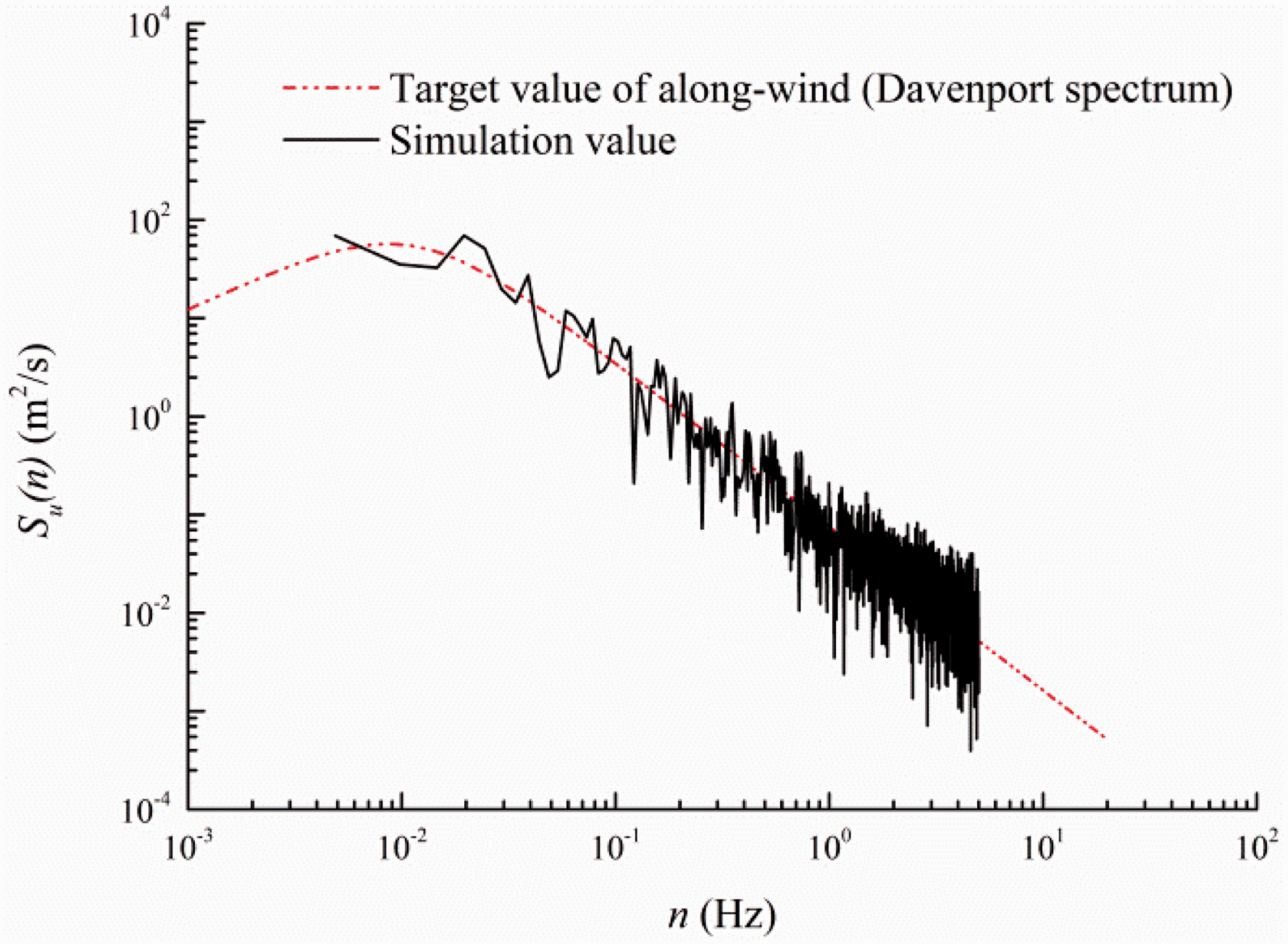
Target and simulated PSD of fluctuating velocity of along-wind.
Wind load
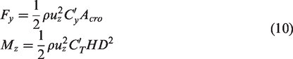
The body dimensions of the tower crane are small relative to the turbulence integral scale of the atmospheric boundary layer, and the effect of structural motion on fluctuating wind pressure can be ignored. Therefore, the fluctuating wind load on the tower crane is in accordance with the quasi-steady assumption,
41
which posits that the wind coefficient of the buffeting is approximately equal to the mean wind coefficient from the CFD numerical simulation. The wind load of each partition of the tower crane can be obtained according to the Bernoulli equation through the fluctuating wind velocity, mean wind velocity and mean wind coefficient of the respective aforementioned partitions. The along-wind load 
The time history of fluctuating wind load of each partition was obtained using MATLAB®. To facilitate the application of wind loads to the FEM of the tower crane, the wind loads of the various partitions are equally divided into the nodes of the corresponding segments, which means that the wind load on each node of a partition is equal. The time history of fluctuating wind load, which was defined as table file, was applied to the FEM of the tower crane to carry out transient calculation by self-editing Ansys Parameter Design Language (APDL) commands. The following Figure 8 is the time history of the along-wind load of a node in partition number 4.
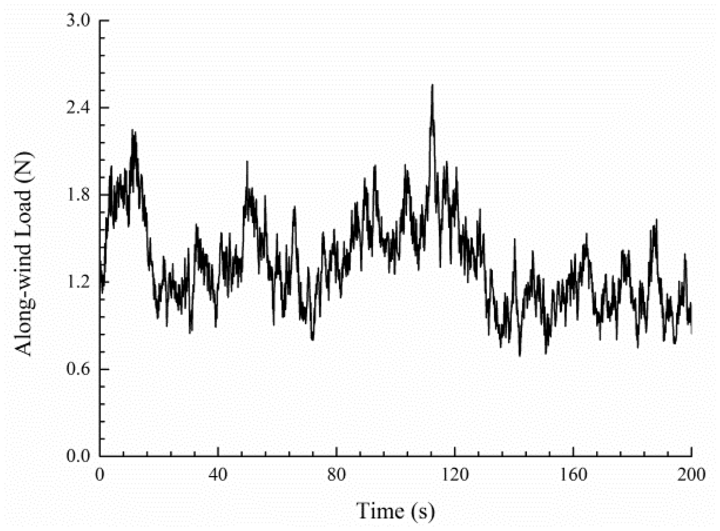
Time history of the along-wind load of a node in partition number 4.
FE modelling and modal analysis
FEM of the tower crane
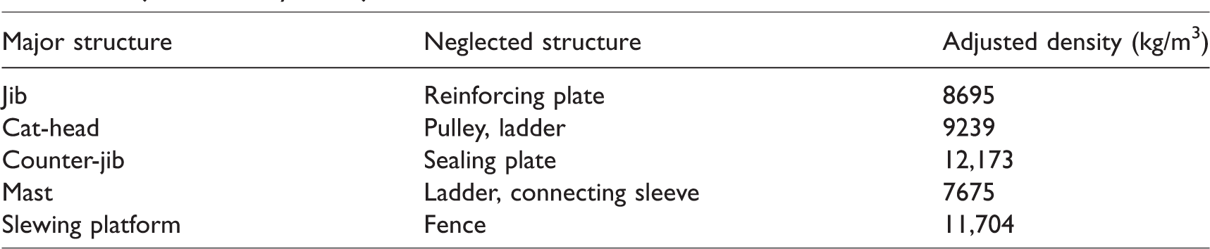
According to the simplified tower crane model in which the components with a small windward area were removed in section ‘Grids’, the corresponding FEM with the material properties of Q235B is established. However, the removed components have a certain contribution to the mass of the tower crane. The mass distribution of the established FEM will be different from the actual structure if they are neglected, which will limit the accuracy of the dynamic response of the tower crane under wind loads. Therefore, the mass of these components must be added to the established FEM. The FEM can have a mass distribution similar to that of the actual structure by adjusting the density of the main structure of the tower crane. The adjusted density of major structure is shown in Table 2.
Adjusted density of major structures of the QTZ125 tower crane.
The FEM of the tower crane was established in the commercial software ANSYS®. The beam189 element was applied to simulate the counter-jib, cat-head, jib and mast, which were mainly composed of slender beams; the link 10 element was applied to the pull rod of tower jib and counter-jib, which were mainly bearing axial force; the mass21 element was applied for the hoisting mechanism, luffing mechanism, counterweight, and hook. Six degrees of freedom (DOFs) of most of the first section of the tower mast were restricted because it was fitted into a foundation of cement, and only the three DOFs of the rotation were released in the connected area of the anchorage device with the tower mast. The node number of the FEM of the tower crane is more than 12,000, with more than 70,000 DOFs.
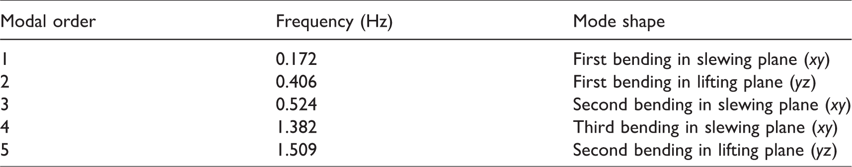
Modal frequency and mode shape
The structural characteristics predicted by the FEM of the tower crane often inevitably deviate from the measured results. Therefore, it is necessary to update the FEM based on the measured response to ensure the accurate dynamic response of the tower crane under wind loads. Modal frequency and mode shape are the intrinsic characteristics of the dynamic response of the tower crane. Based on the FEM of the tower crane established in the previous section (without considering the boundary conditions of anchorage device), Qin et al. found that the identified mode shape based on the measured response results is consistent with finite element analysis, but the maximum relative deviation of modal frequencies is 18.5%. Therefore, seven structural parameters with a large influence on the tower crane response results are selected as the updated parameters; the top four modal frequencies are defined as the objective function, and an FEM-updating method based on response surface is proposed. To improve the computational efficiency, the explicit functional relationship between the structural response and the updated parameters is obtained to replace the traditional FEM, and the updated FEM of the tower crane is realized by iterative optimization. The maximum relative deviation of modal frequencies between the updated FEM and the measured results is only 1.2%. 42 The abovementioned updated FEM is adopted in this study for the analysis. In addition, two anchorage devices are established to ensure structural safety in actual working conditions according to the crane design rules. Therefore, this study considers the boundary conditions of the anchorage device in the updated FEM of tower crane. The modal frequencies and mode shapes are presented in Table 3 and Figure 9.
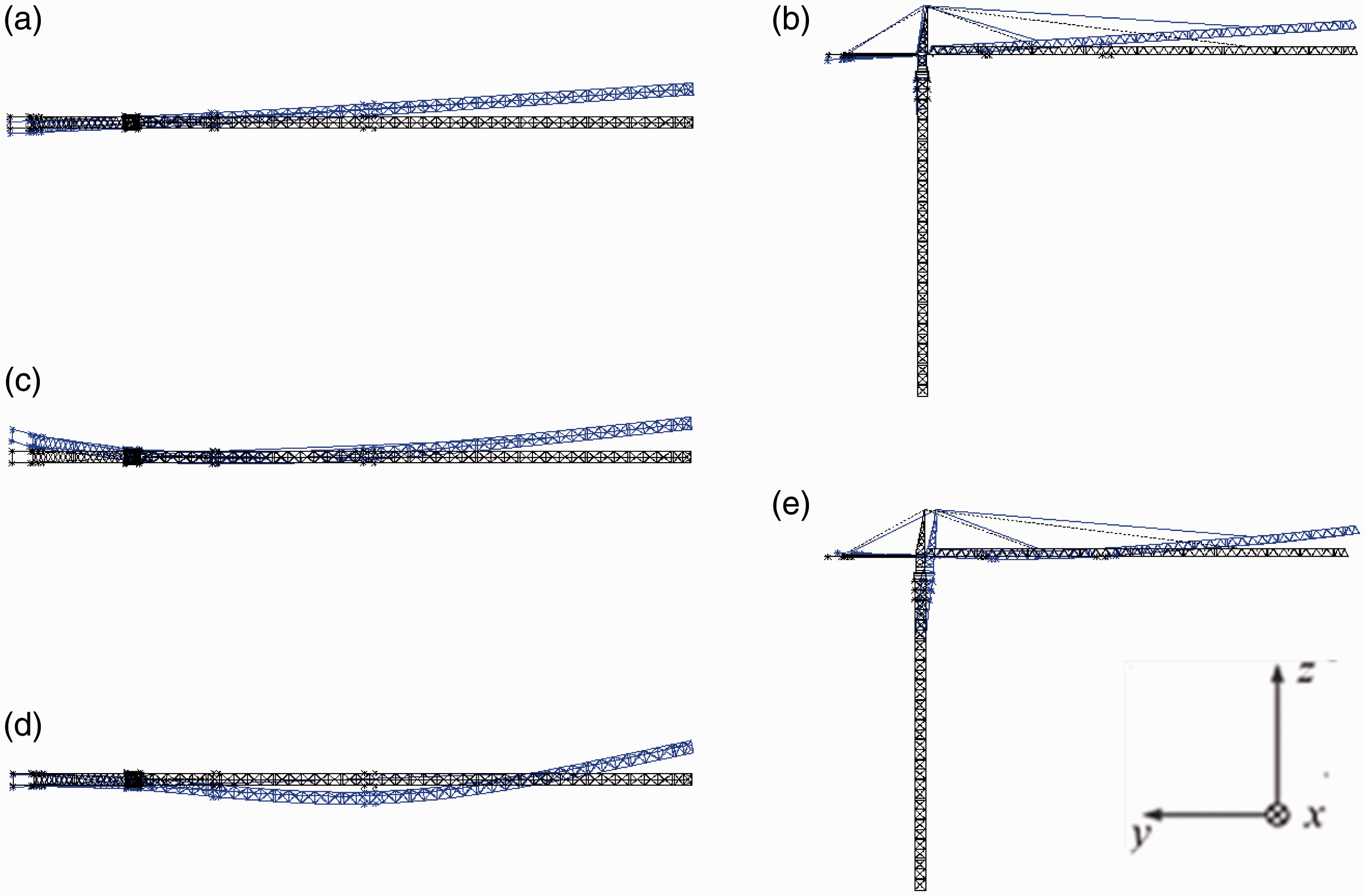
Mode shapes of the tower crane. (a) First mode shape, (b) second mode shape, (c) third mode shape, (d) fourth mode shape, (e) fifth mode shape.
Modal frequencies and mode shapes of the tower crane.
Safety evaluation
Safety under static wind load
According to the design rules for cranes,
2
the static deflection of the distal section of tower jibs under the force of gravity is

According to the rules, the wind load of a tower crane in the working conditions is processed as static load

Safety under fluctuating wind load
Dynamic responses are significant characteristics for evaluating the safety of a tower crane under wind loads. According to the FEM of the tower crane established in the previous section, the mass matrix and stiffness matrix of the system equations of structural dynamics can be obtained. Rayleigh proportional damping is adopted, 43 and the damping ratio of structures is 0.029. The Newmark step-by-step integration method is applied to solve the system equations of structural dynamics. To guarantee the accuracy of the results, the time step is 0.02 s, which can consider at least the top five modal frequencies, and the total time for the calculation is 210 s.
Displacement and acceleration responses
The displacement and acceleration responses of the tower crane under fluctuating wind loads are important indexes to reflect the safety of the structure. Unstable or fatigue damage of the tower crane with large alternating stress will be present under the action of fluctuating wind loads. The tower crane can be regarded as a cantilever structure, and the larger displacement of the tower crane will appear in the distal end of the tower counter-jib, jib and cat-head. The wind load of pull rods (partition numbers 32–35) are lower with a small windward area, and their FEMs are only able to withstand the axial force with the link10 element; thus, their dynamic responses were not considered in this study.
Figure 10 shows the maximum displacement of different partitions in the x and y directions. With the deflection of the wind direction, the displacement of the mast in the x and y directions is quite small, which indicates that the anchorage device of the tower crane is remarkable for the wind-resistant performance. The displacement of the jib in the x and y directions increases substantially, while the maximum displacement appears in the 0° wind direction. This result indicates that the maximum wind load of the tower crane emerges in the position of deflecting a certain angle in the positive direction. However, the most unfavourable condition is in the 0° wind direction. The positive and negative alternating phenomenon appears in the maximum displacement of the partition of the tower crane under different wind directions, which shows that the jib and the counter-jib display torsional effects. The structural strength of the region near the slewing platform should be increased to reduce the probability of accidents.
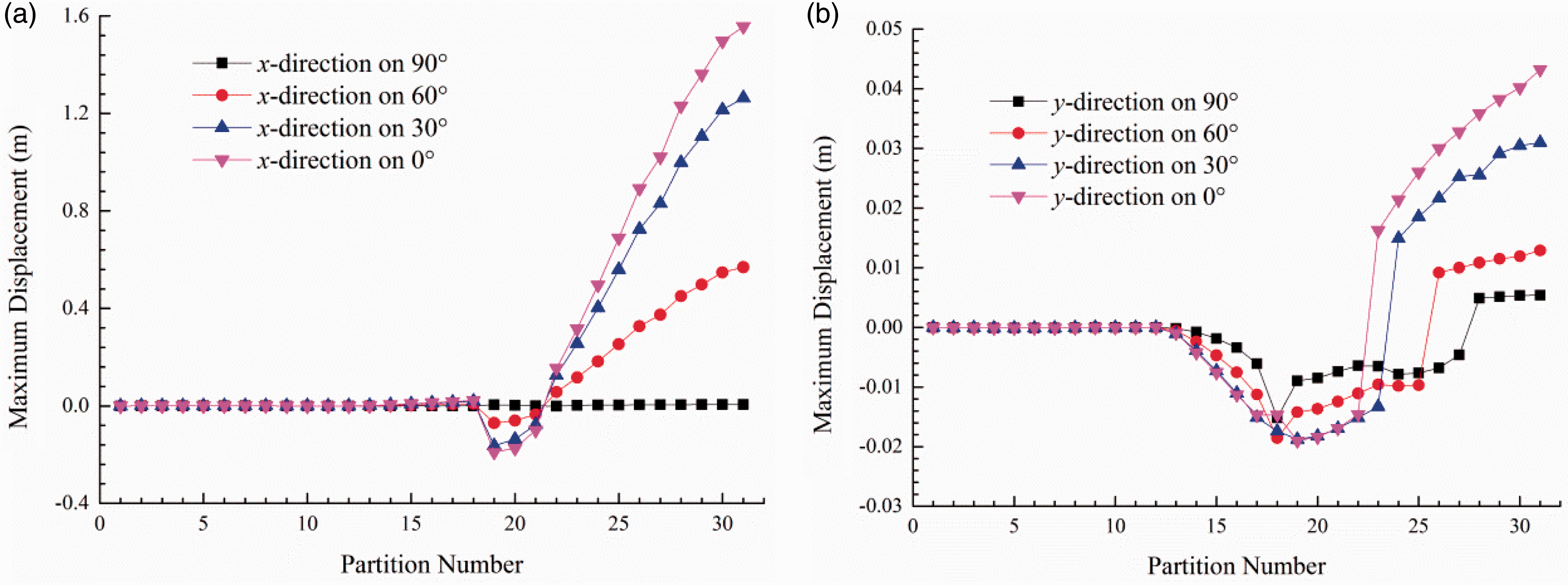
Maximum displacement of partitions in x-direction (a) and y-direction (b) under different wind directions.
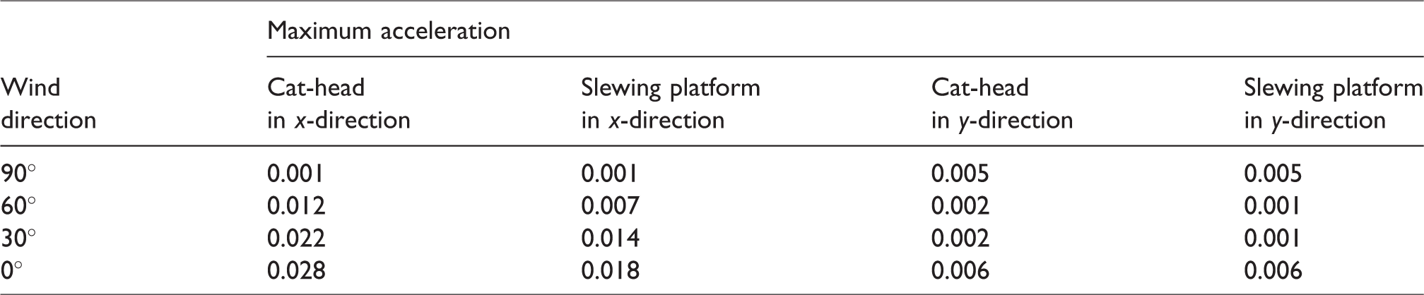
Table 4 presents the maximum acceleration of the cat-head and slewing platform in different wind directions. The maximum acceleration of the cat-head, 0.028 m/s2, appears in the 0° wind direction, and the maximum allowable acceleration of the structure is 0.28 m/s2 according to the Chinese standard JGJ99-2015, 44 so it meets the comfort requirement for the operator in the working conditions.
Maximum acceleration in different wind directions (unit: m/s).
The displacement PSD under different wind directions were obtained through periodogram method of classical non-parametric power spectrum density estimation. In this process, the stochastic signal was processed with Hanning window function. The sampling time is 210 s, and the sampling frequency is 50 Hz. The displacement PSD of the control node of jib (maximum displacement) from 0° to 90° wind directions is shown in Figure 11. The peak frequency of the y direction and the x direction is consistent, but the power of the x direction is greater than that in the y direction because of the dominant role of the along-wind load. There is a peak frequency near 0.2 Hz under different wind directions, and the peak frequency tends to slowly increase as the wind direction decreases. Especially in the 30° and 0° wind directions, the peak frequency is very close to the first-order modal of the tower crane. In other words, the first-order bending on the slewing plane has been aroused. If the wind speed increases, the wind-induced vibration of the tower crane will be more obvious, and it is necessary to add a vibration control device.
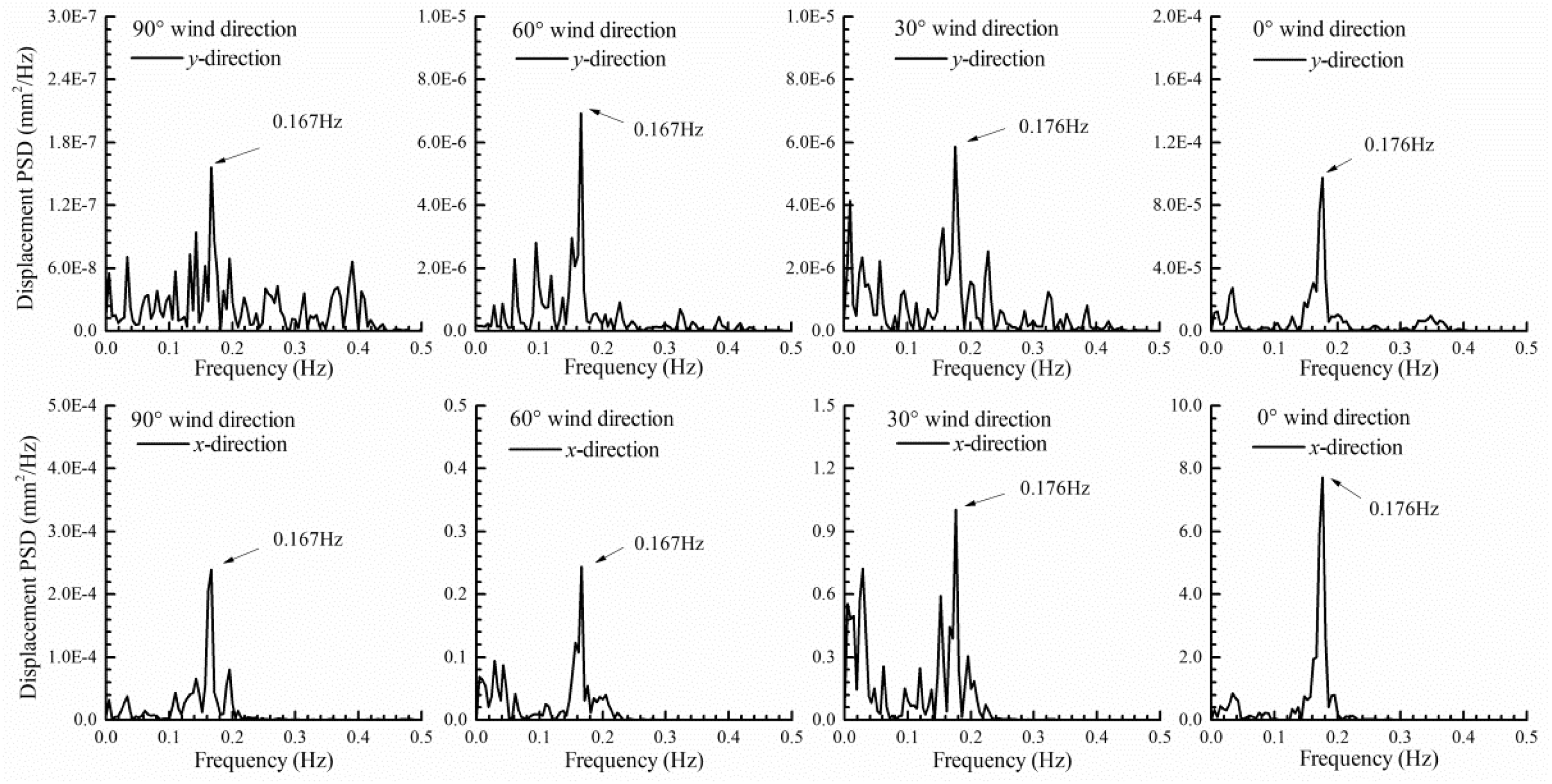
Displacement PSD of the jib in different wind directions (partition 31).
Stress response
The maximum bending stress and axial stress of each partition of the tower crane under wind loads from 0° to 90° wind directions are shown in Figure 12. The maximum axial stresses under fluctuating wind and static wind loads are similar, and they are within the allowable stress range. However, the maximum bending stress between them is different; the maximum bending stress of the junction between the jib and the slewing platform, the counterweight and the counter-jib, exceed the allowable stress under fluctuating wind loads. The structure should be strengthened or other materials such as Q345 should be used in these regions to ensure the safety of the tower crane structure. The gravity of the counterweight has a large influence on the counter-jib compared to the effect of wind loads, in that the counter-jib of the tower crane is mainly subjected to bending stress under the action of wind loads, while the jib is mainly subjected to axial stress. The stress value of the mast is very small under the action of the anchorage device; the anchorage device can effectively improve the wind-resistant performance of the tower crane. The maximum bending stress and axial stress of each partition decreases with the increase in wind direction angles, which also shows that the most dangerous working condition is in the 0° wind direction.
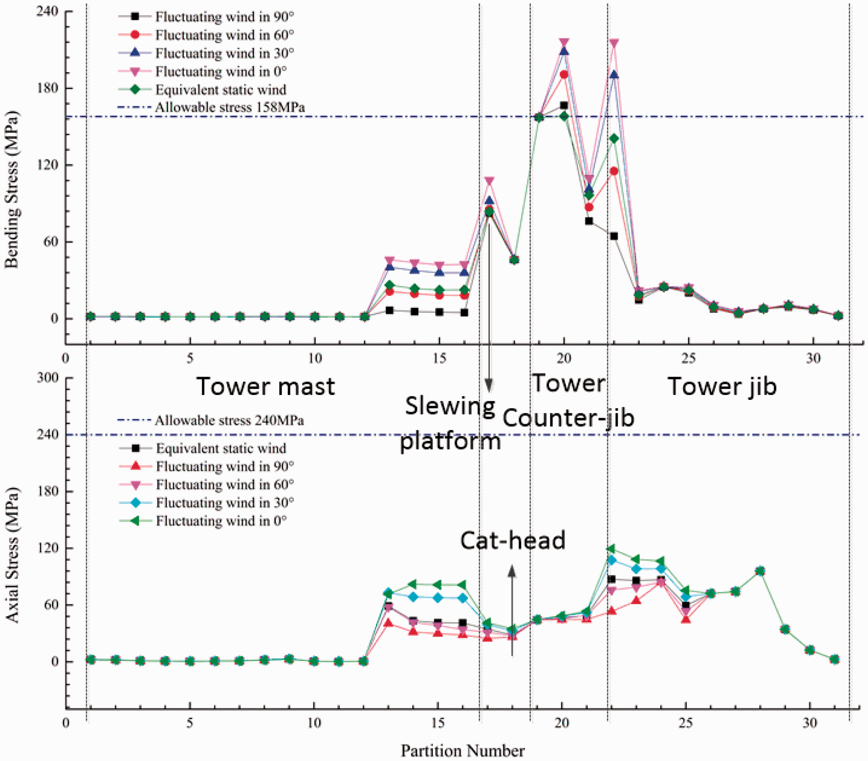
Maximum bending stress and axial stress of the tower crane in different wind directions.
Conclusions
In this study, a general scheme for the tower crane under fluctuating wind loads is presented. This scheme can be used to accurately estimate the safety based on the CFD method and time domain wind-induced responses analysis. The significant conclusions drawn from the numerical simulation are summarized below:
The maximum along-wind load of the tower crane did not appear in the 0° or 180° wind directions but deflected within 30°–60°. However, the maximum displacement, bending stress and axial stress of the tower crane were in the 0° wind direction under fluctuating wind loads. The most unfavourable wind load direction is the 0° wind direction for the tower crane. The angle between the across-wind load direction and along-wind load direction varied in 90° or 270°. Furthermore, the wind coefficient of across-wind was small, yet the maximum of the ratio of the absolute value to the wind coefficient of along-wind reached 17.9%, and the mean was approximately 8.56%. The across-wind loads should be considered in the wind-resistant design of tower cranes. The static deflection and the strength of the tower crane under gravity and the static wind loads met the requirements of design rules for cranes. The maximum acceleration of the cat-head was 0.028 m/s2 under the fluctuating wind load, which met the comfort requirements of the operator in working conditions. However, the maximum bending stress of the junction between the jib and the slewing platform, the counterweight and the counter-jib, exceeded the allowable stress, and the first modal of the tower crane was excited. These results warrant the consideration of the effect of fluctuating wind loads in the safety analysis of tower cranes.
Footnotes
Declaration of conflicts of interests
The author(s) declare that there are no conflicts of interest regarding the publication of this manuscript.
Funding
The author(s) disclosed receipt of the following financial support for the research, authorship, and/or publication of this article: This research was supported by the National Natural Science Foundation of China (51205292), the National Science and Technology Support Program of China (2014BAF08B05, 2015BAF06B05) and the Key Project of Science and Technology of Shanghai (15DZ1161203).