
Abstract
In order to realize the rapid response control for turboshaft engine during the process of variable rotor speed, the linear quadratic Gaussian with loop transfer recovery (LQG/LTR) control method for turboshaft engine based on torsional vibration suppression is proposed. Firstly, the two-speed dual clutch transmission model is applied to realize the variable rotor speed of helicopter. Then, based on the state variable model of turboshaft engine, the proper LQG/LTR controller is available. In order to eliminate the limitation of low-order torsional vibration on the bandwidth of LQG/LTR controller, a frequency-domain analysis method for the effect of torsional vibration suppression on LQG/LTR controller performance is developed. Finally, the numerical simulation is conducted to verify the LQG/LTR control for turboshaft engine with variable rotor speed based on torsional vibration suppression. The results show that the bandwidth of the LQG/LTR control loop can increase by 2–3 times under torsional vibration suppression. Meanwhile, when the rotor speed varies continuously by 40%, the overshoot and sag of the power turbine speed can decrease to less than 2% through LQG/LTR controller based on torsional vibration suppression, which achieves the rapid response control of the turboshaft engine.
Keywords
Introduction
With the wide application of helicopter in various fields, the problems of short flying range, high noise, and limited flight altitude are more obvious. Nevertheless, variable rotor speed tends to be an effective way to solve these problems as one of the rotor variant technology. Different from the conventional constant rotor speed scheme, variable rotor speed technology can improve the operational performance and obtain good acoustic characteristics through adjusting the main rotor speed to adapt to various flight conditions. 1 However, the specific fuel consumption of modern turboshaft engine reaches the optimum in a relatively narrow speed range, 2 therefore, it is necessary to realize the variable rotor speed by changing the gear ratio.
The turboshaft engine drives the main rotor and tail rotor through power turbine, reducers, and drive shafts. These high-speed rotational components constitute a mechanical transmission system together,3,4 which is known as the rotor drive train system. Nevertheless, the torsional elastic characteristics of the rotor drive train system can not only affect the flight quality of the helicopter, but also influence the stability of the turboshaft engine wherein the torsional vibration modal possesses the greatest impact.5,6 It is mainly dependent on the engine and transmission inertias and the equivalent damping and stiffness of the main rotor at the hinge connection part.
In the process of variable rotor speed, helicopter demand torque and engine output torque match each other through clutches with variable gear ratio, which enhances the coupling between helicopter subsystem and engine subsystem and influences the torsional vibration characteristics of rotor drive train system significantly. The uncertainty of torsional vibration modals in the variable rotor speed makes it difficult to suppress the torsional vibration well and brings great challenges to the design of turboshaft engine controllers. Therefore, it is necessary to develop high-quality control methods for the turboshaft engine with the variable rotor speed based on the torsional vibration suppression.
The study on the variable rotor speed of helicopter has been conducted early. In 1953, the U.S. Air Force applied the two-speed gear devices to the H-5 helicopter successfully. 7 Subsequently, this transmission system was introduced to tiltrotor. The XV-15 tiltrotor and V-22 tiltrotor can operate at two different rotor speeds. 8 Litt et al. 9 proposed a torque sequence scheme for the variable rotor speed based on the integrated linear UH-60 helicopter/T700 engine model to reduce cruise noise and fuel consumption. Misté et al.10,11 obtained the most economical speed regulation law in the flight envelope through different helicopter structures based on the nonlinear UH-60 helicopter/T700 engine dynamics model. However, they only considered the effect of the variable rotor speed on the performance and stability of helicopter or engine, but failed to take into account the whole propulsion system.
In recent years, modern control theory has attracted extensive attention. Many achievements have also been made in the application to the design of aero-engine control system. Among them, the most popular control methods are linear quadratic regulator (LQR) control, H∞control, and linear quadratic Gaussian (LQG)/LTR control. LQR control is sensitive to model precision. Taking into account the constraints in the real flight, it has not been available in practice. 12 Yan 13 proposed a design method of H2/H∞ robust control law based on linear matrix inequality (LMI). In addition, he designed a multivariable robust controller of turboshaft engine for speed closed-loop control in the helicopter autorotation process. The results showed that this method can significantly improve the sensitivity of turboshaft engine to load and reduce the sag of power turbine speed effectively. Jaw and Mattingly 14 adopted the LQG/LTR control method to reduce the overshoot of the power turbine speed based on the reduced-order model of helicopter/engine. The response bandwidth is doubled compared with the LQR control method, which realizes the rapid response control of the turboshaft engine. However, the dynamic influence of the mechanical torsional vibration on the controller and response is not taken into account in the above researches.
Therefore, in order to compensate for the lack of research on LQG/LTR control method for turboshaft engine with variable rotor speed based on the torsional vibration suppression, the two-speed dual-clutch transmission model is introduced based on the integrated helicopter/engine model firstly. Then, based on the state variable model of the turboshaft engine, the LQG/LTR controller is available. However, due to the existence of low-order vibration, the LQG/LTR controller is difficult to achieve the rapid response. Therefore, the effect of the torsional vibration suppression on the LQG/LTR controller is analyzed from the time and frequency domains. Finally, based on the torsional vibration suppression, the control effect of the LQG/LTR controller for the turboshaft engine with variable rotor speed is verified and compared with the augmented LQR controller.
Two-speed dual-clutch transmission model
Compared with the conventional transmission mechanism with planetary gears, the dual-clutch transmission (DCT) based on the differential planetary gears not only can obtain a larger gear ratio, but also is beneficial to reduce the weight of the transmission mechanism and balance the load. Different from continuously variable transmission 15 (CVT), this gearbox configuration realizes speed change via gear shifting through a split-path differential planetary arrangement. As shown in Figure 1, the high-speed ratio is available by disengaging a ring clutch and engaging a set of planet clutches. On the other hand, disengaging the planet clutches and locking the ring gear can obtain a low-speed ratio. In the low-speed case, the power is split between two parallel paths that has the advantages of allowing an overall lower transmission weight. The corresponding kinematic diagram of two-speed DCT is shown in Figure 2.
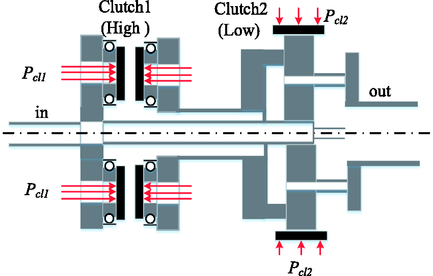
Two-speed DCT diagram.
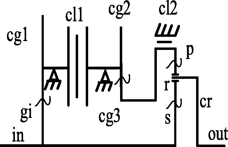
Two-speed DCT kinematic diagram.
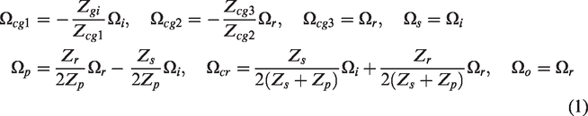
The rotation speed kinematics of the DCT are as follows

To simulate the dynamic characteristics of DCTs, a rigid body dynamics model is available that consists of the DCT kinematics, the gear rotational inertias, and the nonlinear clutch friction torques.
16
The equations of motion have the form

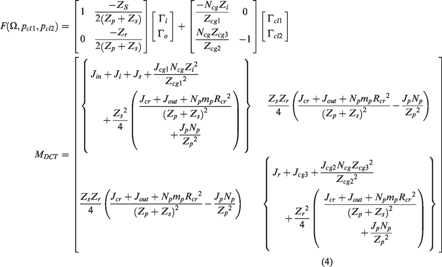
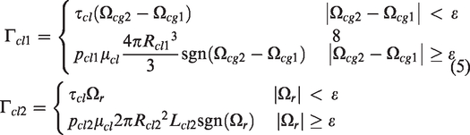
According to these equations, taking engine output torque and rotor demand torque as inputs, the continuous variation of DCT gear ratio is available through applying different clutch loads.
LQG/LTR control method
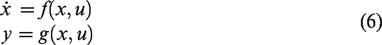
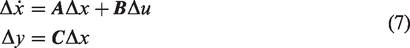
The nonlinear model of turboshaft engine can be expressed as follows
The LQG/LTR control is a robust control method developed based on modern control theory. 18 It combines the linear quadratic regulator and the linear time-invariant Kalman filter. The control system can obtain the desired loop recovery gain and has good performance and disturbance rejection ability. Therefore, it has been applicable in the aero-engine control system.
In order to overcome the poor robustness of the LQG method, 19 the LTR procedure is applied. Therefore, the whole design is divided into two independent steps: (1) designing the target feedback loop (TFL) to have the desired function; (2) recovering the transfer function of the target feedback loop.
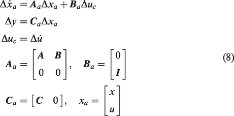
In order to eliminate the steady-state error of the control loop, an integral link is applied in the design of the target feedback loop. Augmenting the controlled object, the following model is available and the structure diagram of the augment system is shown in Figure 3.
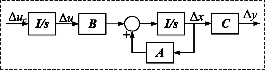
Structural diagram of the augment system.
Therefore, the transfer function of the target feedback loop based on Kalman filter is as follows

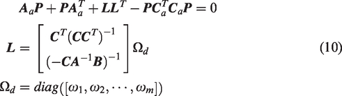
According to the target feedback loop, the transfer function matrix of the LQG/LTR compensator is


Equation (13) summarizes the state-space form of the LQG/LTR compensator shown in equation (11). e and
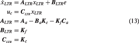
Control structure diagram of LQG/LTR.
According to the above equations, the LQG/LTR robust controller is available based on the state variable model of the turboshaft engine.
Closed-loop dynamic characteristics of power turbine speed under torsional vibration suppression
Torsional vibration characteristics of rotor drive train system
Helicopter generally adopts the turboshaft engine as power devices, resulting in the low-order torsional vibration frequency of the rotor drive train system unexpectedly falling into the response bandwidth of the engine. If the control system is hardly proper, it will easily lead to unstable torsional vibration and cause self-excited vibration. Therefore, a torsional vibration filter is indispensable in the control system of the turboshaft engine. The simplified rotor drive train system of helicopter is a five-degrees-of-freedom model that consists of fuselage, engine, transmission, hub, and rotor, 20 as shown in Figure 5. The simplified rotor drive train system is a multi-degrees-of-freedom coupling system, which can accurately express various dynamic modals.
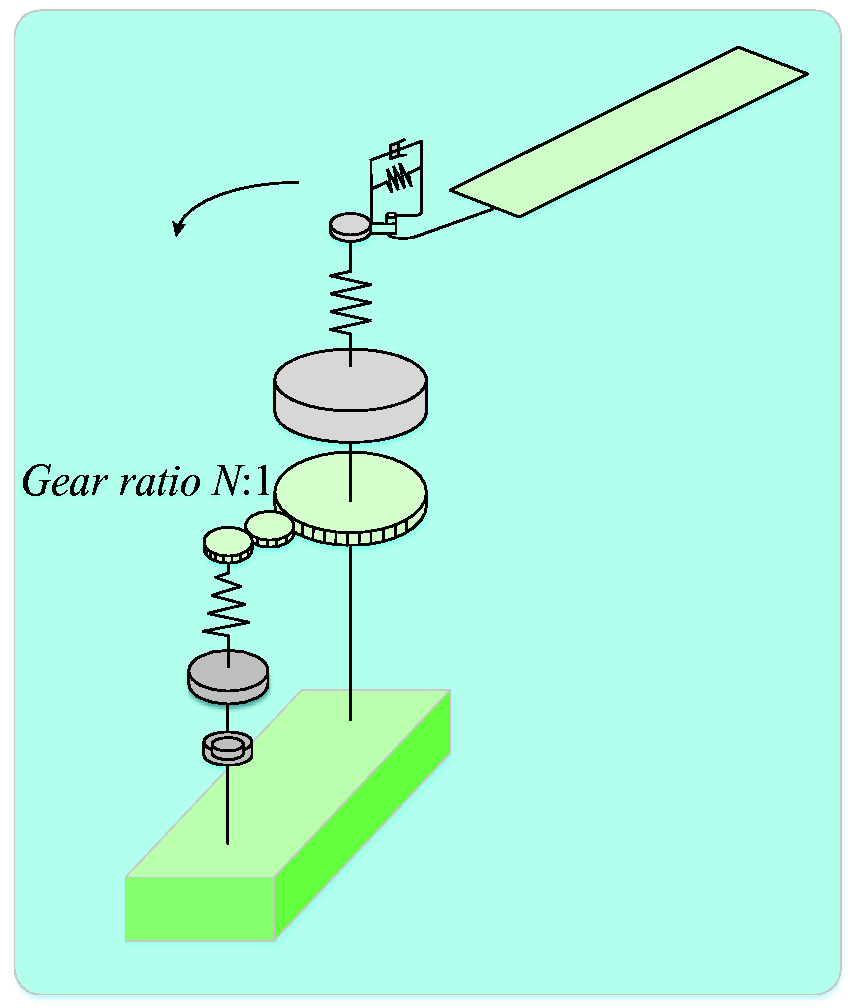
Simplified helicopter rotor drive train system.
For the simplified rotor drive train system, the torsional vibration equation is a set of second-order ordinary differential equations including mass matrix
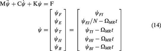
According to the inverse matrix and the adjoint matrix, the frequency response function between the torsional vibration (ψ(2)) and the load(F(2)) of the engine can be expressed as follows

Figure 6 summarizes the Bode plot of the simplified rotor drive train system. As shown, the simplified system has two torsional peaks corresponding to two vibration modals, which ignore the dynamics of the tail rotor. The first frequency is produced by the main rotor to the engine and gearbox. The second one is the dynamics of the engine to the gearbox. Because the first modal has the lowest torsional vibration frequency and high peak, it is necessary to design a proper filter. Otherwise, it will cause torsional vibration instability.
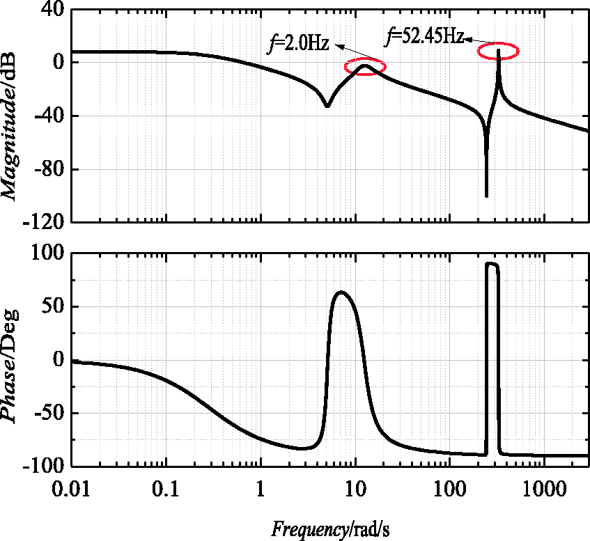
Bode plot of the simplified rotor drive train system.
Analysis of the effect of torsional vibration on power turbine speed on based on LQG/LTR controller in frequency domain
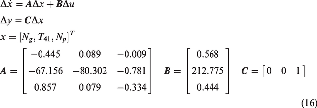
Taking the fuel flow Wfb and the power turbine speed Np as the input and the output respectively, the state variable model shown in equation (7) can be rewritten as follows: the state vector is the gas turbine speed Ng, temperature before turbine T41, and power turbine speed. Equation (16) is available via the least squares fitting at the flight altitude of H = 200 m, the forward speed of vc=118 m/s, the initial fuel flow of u0=0.25 kg/s, and the initial state vector of x0= [95.51, 1429.04, 71.58]T.
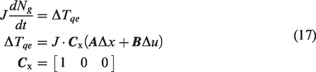
According to equation (17) and the moment balance equation of the rotor, the relationship between the engine output torque and fuel flow is available, wherein J is the moment of inertia. As shown in equation (15), in a real turboshaft engine, the torsional vibration (ψ(2)) and the load (F(2)) can be represented by the increase in the power turbine speed (ΔNP) and engine output torque (ΔTqe). Equation (18) describes the transfer function of a second-order notch filter designed at the first torsional frequency (
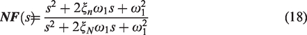
The closed-loop structure of power turbine speed control with LQG/LTR.
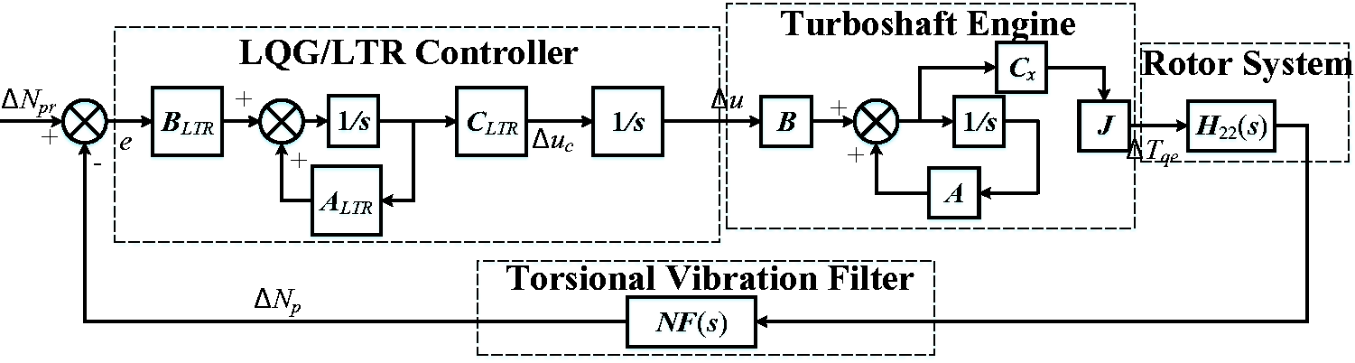
As shown in the figure, the whole control structure consists of engine, rotor, power turbine control, and torsional vibration filter. Figure 8 summarizes the closed-loop magnitude–frequency curve of the power turbine speed and the unit step response at t = 1 s as shown in Figure 9.
Magnitude–frequency curve of Np with the closed loop.
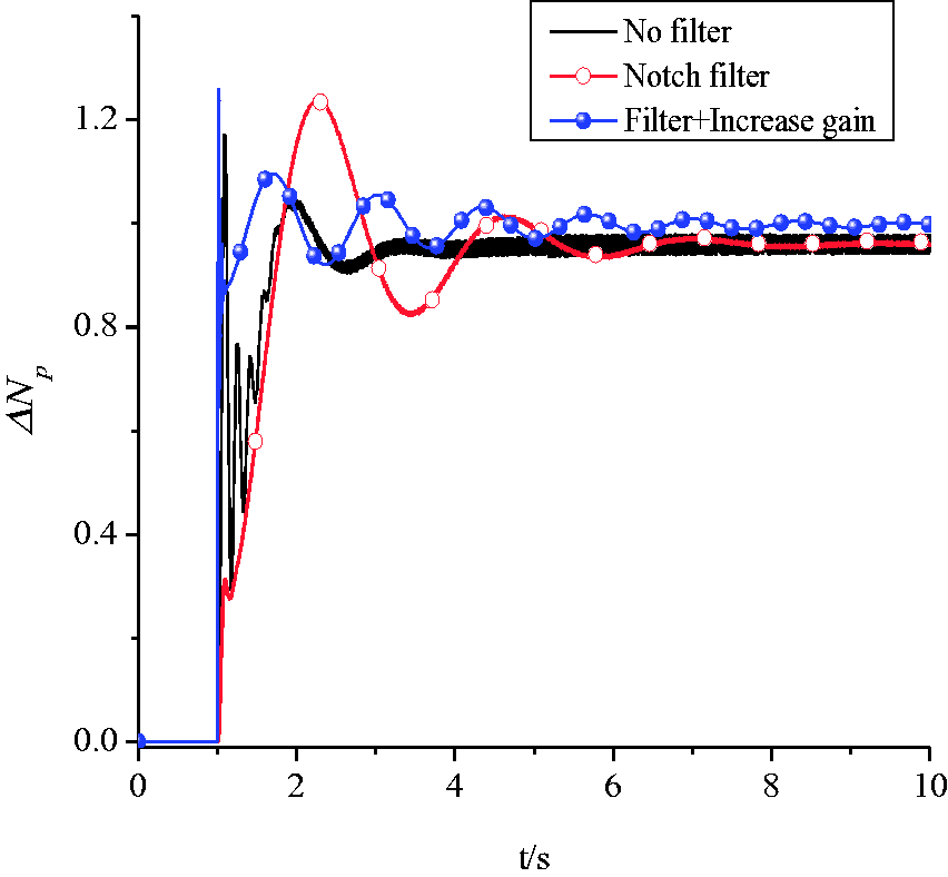
The curve of unit step response.
As shown in Figure 8, the first-order torsional peak appears at 12.6 rad/s (2 Hz) without any torsional vibration filter. In order to prevent the first-order torsional frequency from falling into the bandwidth of the fuel control system, the bandwidth of the control loop is generally 3–4 rad/s. When the notch filter is applied, the first-order torsional peak is effectively damped with the response lag. Fortunately, after applying the notch filter in the control loop, the bandwidth can increase by 2–3 times without the risk of coupling resonance. Figure 9 summarizes that the response speed of power turbine speed improves significantly with the increase of the bandwidth.
Verification of LQG/LTR control method based on torsional vibration suppression with variable rotor speed
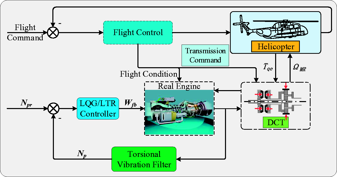
Figure 10 summarizes the structure of the LQG/LTR control for the turboshaft engine in the integrated helicopter/engine system with the variable rotor speed. As shown, the power turbine speed is firstly attenuated by the torsional vibration filter, and then enters into the LQG/LTR controller to realize speed closed-loop control, so that the power turbine speed can keep the reference command constant. The reference command is usually set to be 100%. The pitch controller is applied to the flight control system to track the flight command.21,22 To realize the variable rotor speed, a two-speed DCT model is introduced. In the simulation of the integrated model, the flight control system generates the transmission command according to the system state to achieve the control objectives. The verification for torsional vibration suppression with variable rotor speed is conducted, and the results are shown in Figure 11.
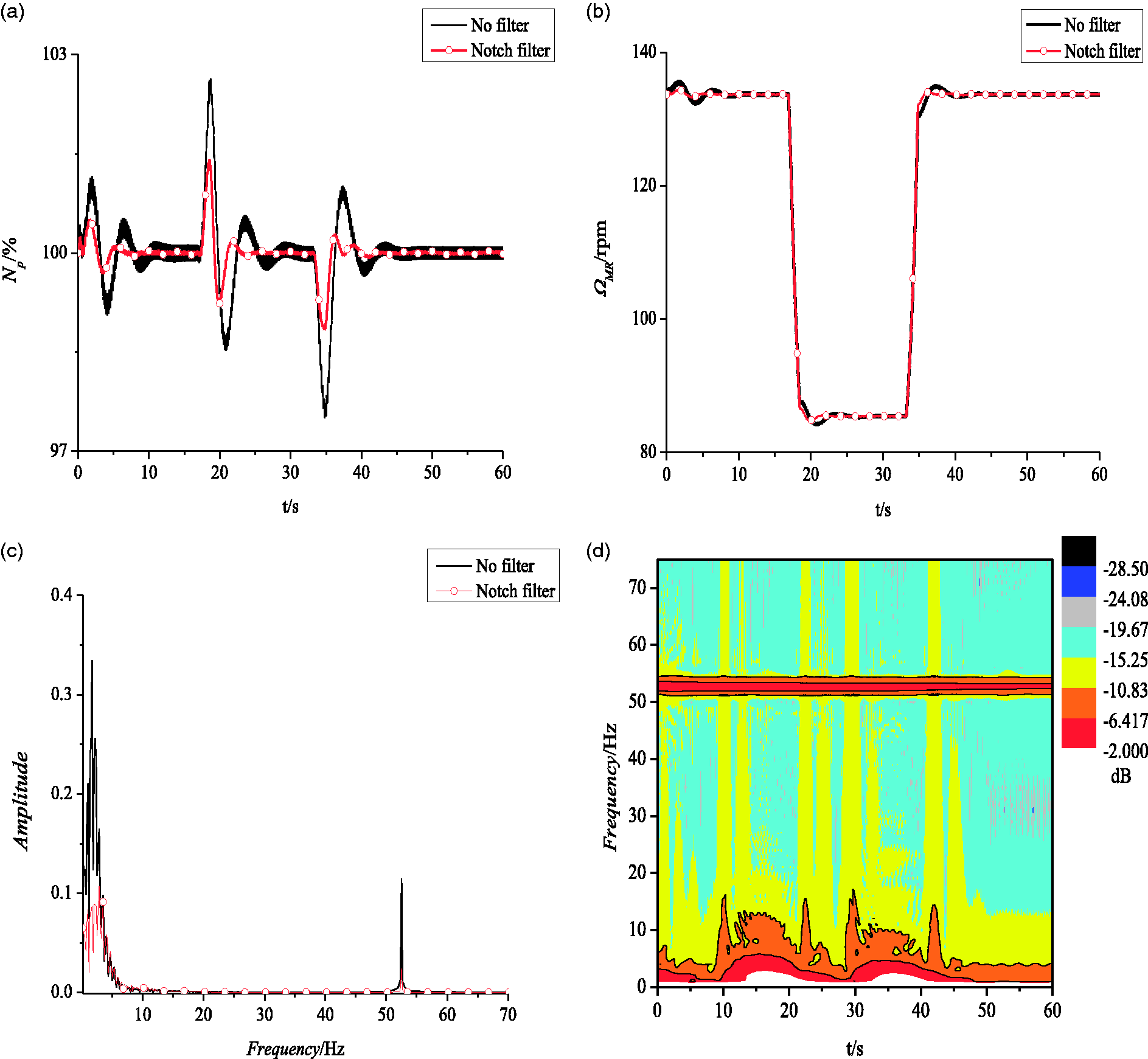
Structural diagram of LQG/LTR control for variable speed helicopter/engine: (a) power turbine speed; (b) main rotor speed; (c) FFT of Np; (d) SFFT of Np without notch filter.
Comparison of the engine parameters before and after notch filter.
As shown in Figure 11(b), the application of two-speed DCT can make the rotor speed Ω MR vary by 40% continuously. When Ω MR changes sharply, the engine output power can hardly match the rotor demand power, resulting in instantaneous overshoot and sag of the power turbine speed Np (as shown in Figure 11(a)). Figure 11(d) summarizes the short-time Fourier transform (SFFT) of the power turbine speed. As shown, the instantaneous variation of the rotor speed excites the low-order torsional vibration promptly without any filter, and the first-order torsional frequency varies with the rotor speed. In the whole process, the high-order torsional modal exists all the time. According to the fast Fourier transform (FFT) of Np shown in Figure 11(c), the notch filter with proper bandwidth can suppress low-order torsional peak effectively with the amplitude decreasing by about 60%. The effect of the torsional vibration suppression is remarkable.
Next, the rapid response control of LQG/LTR for the turboshaft engine based on the torsional vibration suppression is verified at the flight altitude of H = 200 m and the forward speed of vc=118 m/s. Figure 12(a) summarizes the load on the two-speed DCT. As shown, when the clutch executes upshift, the low-speed clutch pressure gradually decreases to zero. Meanwhile, the high-speed clutch pressure linearly increases from 0 to 100 psi to lock the gear. In reverse, the downshift can be executed. However, in the process of transient handoff, when both high- and low-speed clutches are slipping under load, a recirculating power loop is setup resulting in some amount of power being dissipated into heat. The simulation results are shown in Figure 12(b) to (i).
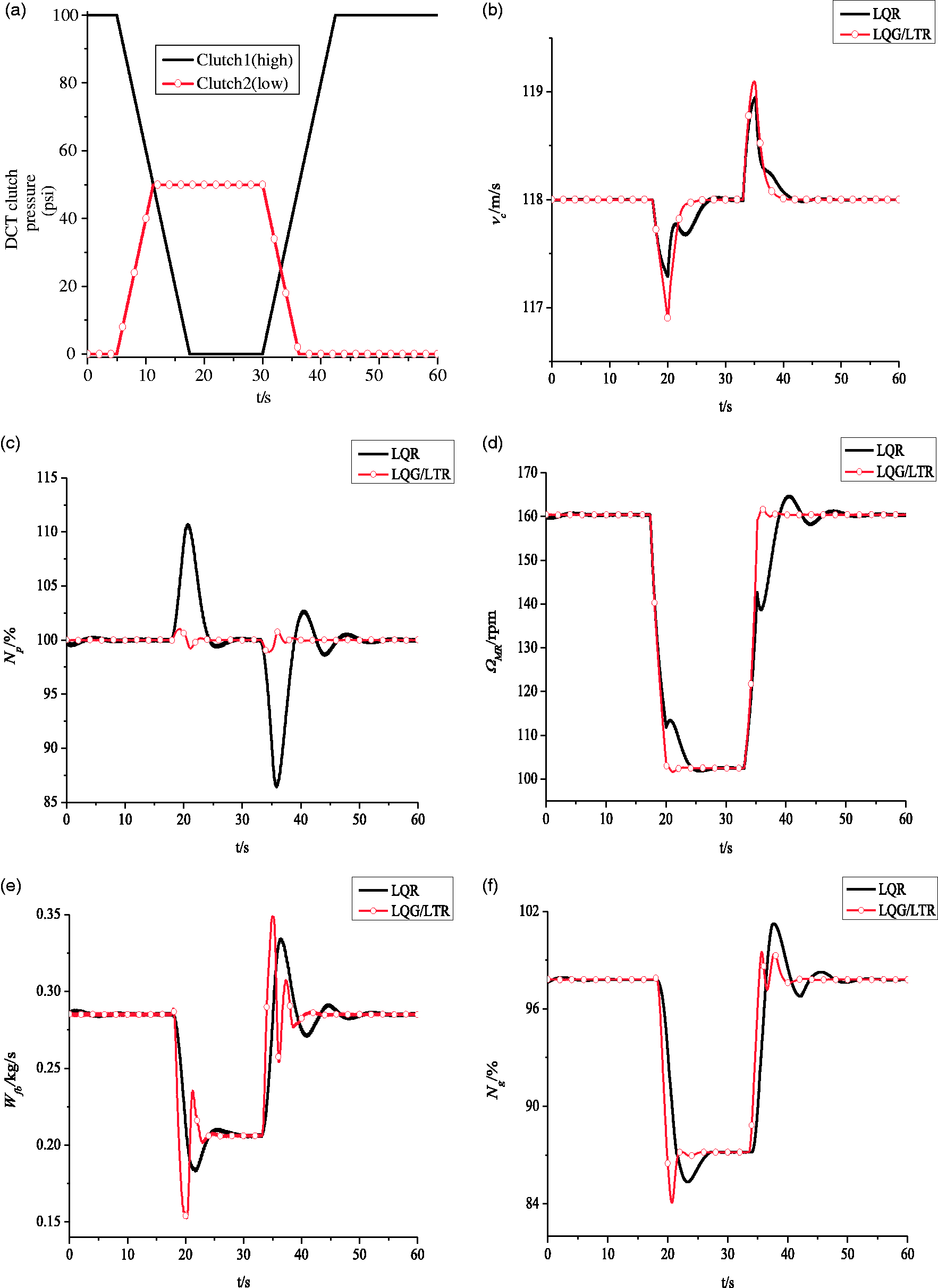
Comparison of LQG/LTR for variable speed helicopter/engine with ALQR controller: (a) load on DCT; (b) forward speed; (c) power turbine speed; (d) main rotor speed; (e) fuel flow; (f) gas turbine speed; (g) engine output torque; (h) main rotor torque; (i) collective pitch.
As shown in Figure 12(b), during the whole process of the variable rotor speed, the forward speed vc basically remains constant. Both the augmented LQR and the LQG/LTR controller can make the rotor speed continuously change by 40% (as shown in Figure 12(d)). However, compared with the augmented LQR, LQG/LTR controller can reduce the overshoot and sag of power turbine speed to less than 2% because LQG/LTR control method is a combination of LQR and Kalman filter (KF). Wherein, KF is applied to the optimal feedback control law as a state estimator, which can significantly improve the response speed. In this case, the fast response control for turboshaft engine with variable rotor speed is achievable. Figure 12(h) shows that when the rotor speed Ω MR decreases continuously, it is necessary to increase the collective pitch to raise the torque, so that the rotor can provide enough thrust. In terms of the main rotor, when the rotor speed decreases, the rotor demand power decreases as well, resulting in the reduction of the engine output power. Nevertheless, because the turboshaft engine adopts constant speed control scheme, i.e. the power turbine speed keeps at about 100%, the engine output torque decreases accordingly to reduce the output power. Figure 12(g) summarizes that when the rotor speed increases, the application of augmented LQR controller makes the overshoot of engine output torque much larger, which seriously threatens the strength of the transmission. According to Figure 12(e), the fuel flow Wfb increases rapidly with the increase of Ω MR . In this case, the gas turbine speed Ng increases to 101.6% rapidly through augmented LQR controller, which has the risk of excess revolutions (as shown in Figure 12(f)). On the contrary, Ng keeps less than 100% during the whole process of variable rotor speed with LQG/LTR controller, which prolongs the service life of the turboshaft engine.
Conclusions
The research on the LQG/LTR control method for the turboshaft engine with variable rotor speed based on torsional vibration suppression is carried out, which realizes the rapid response control for the turboshaft engine with the variable rotor speed. Several conclusions can be drawn:
Based on the effective torsional vibration suppression through notch filter, the bandwidth of the LQG/LTR control loop can increase by 2–3 times without the risk of coupling with low-order torsional vibration, which can significantly improve the response speed of the power turbine. Based on the torsional vibration suppression, LQG/LTR controller can remarkably reduce the overshoot and sag of power turbine speed during the variable rotor speed, which achieves the rapid response control for the turboshaft engine.
Footnotes
Declaration of conflicting interests
The author(s) declared no potential conflicts of interest with respect to the research, authorship, and/or publication of this article.
Funding
The author(s) disclosed receipt of the following financial support for the research, authorship, and/or publication of this article: The work has been co-supported by the National Natural Science Foundation of China (Grant/Award Number: 51576096), Qing Lan, 333 Project and Research Funds for Central Universities (No. NF2018003).