
Abstract
In order to better understand the dynamic behavior and decrease the muzzle vibration of marching tank, a mechanical–electrical–hydraulic integrated dynamic model of marching tank was established based on a novel dynamic co-simulation method. The hydraulic system model was modeled in Amesim and the dynamic model of marching tank was established in RecurDyn based on multi-body system theory, vehicle terramechanics, and gun launch dynamics. The control system model was modeled in MATLAB/Simulink. Therein, the adaptive robust control algorithm was introduced to design the vertical stabilizer controller and the simulation program of the designed controller was developed by C language. The simulation results show that the muzzle vibration of marching tank can be controlled effectively by the ARC method. Furthermore, the muzzle error compensation signal was added in the designed controller to weaken the detrimental effect of the barrel flexibility on muzzle vibration. This work provides an approach to investigate the dynamic behavior of marching tank considering effects among the mechanical, hydraulic, and control subsystems.
Introduction
Firing accuracy is a major index related with performance of guns, and muzzle vibration is an important factor that affects the firing accuracy. 1 Stabilizer is a key component of fire control system that can keep the bore axis of marching tank near the sighting angle 2 and improve the first-round-hit accuracy. Therein, the vertical stabilizer is an electrohydraulic position servo system, which is often used as the loading actuator in the simulation experiences.3,4 There are inevitably some nonlinear characteristics (the change of fluid direction controlled by servo valves, friction, etc.) and various model uncertainties (disturbance uncertainty, parameter uncertainty, etc.). 5 However, traditional vertical stabilizers are usually designed as linear time-invariant systems based on the classical control theory which cannot compensate the nonlinearity of the systems effectively. With the increasing requirements on mobility and firing accuracy of modern tanks, traditional stabilizers don’t meet the system requirements.6,7 Therefore, the modern intelligent control algorithms are introduced to control the vibration of marching tank gun.
At present, the vertical stabilizer controller has been studied based on some modern control theories such as adaptive control, sliding mode control, fuzzy control, and neural network control.8–11 Performances of these controllers are generally superior to the traditiona Proportion Integration Differentiation (PID) controller. But in these studies, the dynamics model of marching tank was simplified as a linear transfer function and the coupling relationships between the mechanical, hydraulic, and control subsystems were ignored. Obviously, the numerical results based on this assumption were not accuracy. With the increasing requirements on high mobility, high initial speed, and high firing accuracy, this deviation is gradually important and cannot be ignored any more. 12 In fact, a tank is a complex system composed of mechanical, hydraulic, and control subsystems. They work together and affect each other. The traditional sequential design method ignores the mutual coupling among the subsystems. As a result, the design results are often not optimal, the cycle of the products design is longer and the additional cost is higher. 13 At present, researches about the property of mechanical–electrical–hydraulic coupling system have been done in the related field.14–17 It is necessary to study the mechanical–electrical–hydraulic integrated dynamic model of marching tanks.
For the controller design, the more accurate system information we know, the better control performance can be obtained. That is, without considering the complexity of the control structure, accurately modeling can obtain better tracking performance. The vertical stabilizer adjusts the piston rod to reduce the maladjustment angle. However, the desired piston rod displacement, velocity, and acceleration are closely associated with the pitch motion of hull. For traditional vertical stabilizer, it is difficult to ensure the accuracy of the controller by only depending on the cradle elevation angular displacement. So the stabilizer control structure needs be improved.
In the past years, Yao et al. 18 put forward a modern control method, whose argument is mathematically rigorous. Adaptive robust control has the advantages and overcomes the shortcomings of the adaptive control and robust control method simultaneously. Its effectiveness has been proved by a large number of researches. 19 The control method has been applied on horizontal stabilizers5,20 and its feasibility was demonstrated through MATLAB simulations. But more researches are needed. In this paper, the nonlinear characteristics and model uncertainties of the electrohydraulic position servo system of vertical stabilizer were considered. A new structure of the vertical stabilizer controller was designed. The adaptive robust control algorithm was introduced to design the vertical stabilizer controller and the simulation program was compiled by C language. By combining the controller with the established electrohydraulic position servo system model of the vertical stabilizer and the dynamic model of marching tank, a mechanical–electrical–hydraulic integrated dynamic model of marching tank was established. Furthermore, the muzzle error compensation signal was added in the designed controller to weaken the detrimental effect of the barrel flexibility on muzzle vibration.
Basic structure and working principle of the vertical stabilizer
The vertical stabilizer is an electrohydraulic type automatic adjusting system and the simplified control block diagram is shown in Figure 1. 11 When tank is on the move, the pitch motion of hull causes the rotation of gun through the trunnion friction torque. Gun deviates from the sighting angle which generating the maladjusted angle. The control signal is calculated based on the maladjusted angle and with the control signal; the piston rod is driven to control the opening size and direction of electrohydraulic servo valve. Therefore, the bore axis of the marching tank can be kept near the sighting angle and the change of the cradle angular displacement becomes zero. Due to the control input of hydraulic servo valve is zero and the valve spool is in middle position, the pressure in the two chambers of hydraulic cylinder is consistent and the bore axis is kept near the sighting angle.
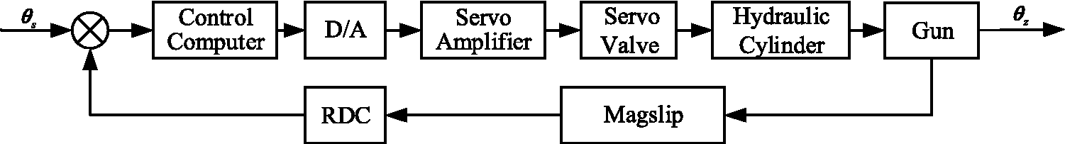
The block diagram of vertical stabilizer.
The main structure of the hydraulic system of the vertical stabilizer is shown in Figure 2.

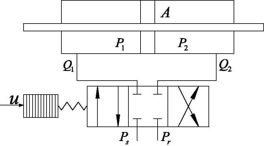
The main structure of hydraulic system.
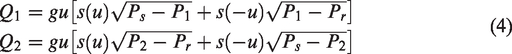
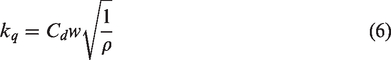
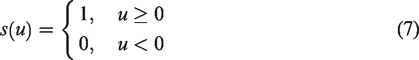
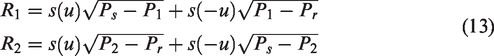
Considering the linear internal leakage and the compressibility of fluid, the pressure dynamics inside the cylinder chambers can be described by
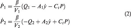
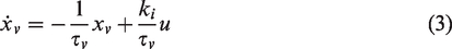
The dynamic equation of servo valve can be approximately described by the first-order element

Controller design of vertical stabilizer
Adaptive robust control
Adaptive robust control integrates the working mechanisms of the adaptive control and robust control. The structure is shown in Figure 3.
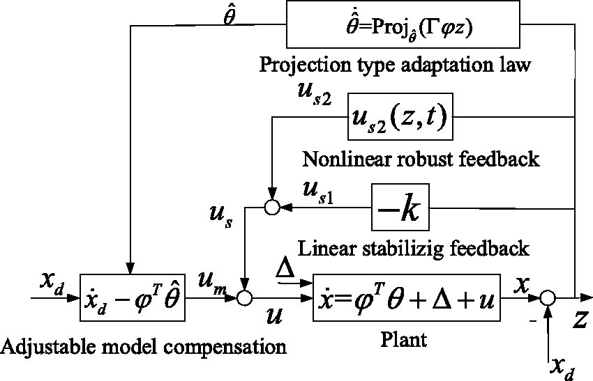
Structure of the adaptive robust controller.
The controlled object
The control structure design of vertical stabilizer
According to the basic structure and working principle of the vertical stabilizer, the control law is designed based on the feedback tracking error. And the error is eliminated by exerting negative feedback control on the vertical stabilizer. The traditional vertical stabilizer is designed only by the cradle elevation angular displacement. Without considering the complexity of the control structure, the controller needs to be accurately modeled to obtain better tracking performance.
The installation location of hydraulic cylinder is shown in Figure 4. So the displacement of piston rod can be expressed by


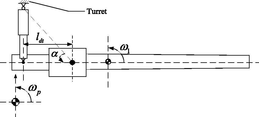
Installation location of hydraulic cylinder.
The maladjustment angle of marching tank is mainly caused by the pitch motion of hull which should be considered when designing the control system of the vertical stabilizer. The adaptive robust controller present in this paper can monitor the displacement, velocity, acceleration of piston rod, and the pressures in the two chambers of hydraulic cylinder in real time. It can guarantee the actual displacement of the piston rod tracking the desired displacement steadily. Then the gun stability can be ensured and the muzzle vibration can be controlled. The desired piston rod displacement can be calculated according to equations (8) and (9). And the actual value of pitch motion can be measured by the gyroscope installed on the hull.
Design of adaptive robust controller
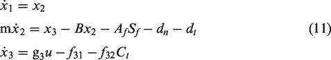
Before designing the controller, the mathematical model of the electrohydraulic position servo system of the vertical stabilizer needs to be rewritten into the state space form.
13
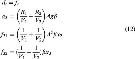
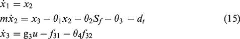
According to the nonlinear model represented by equations (1)–(3), the state variables are defined as

The hydraulic dynamic system can be expressed in a state-space form as
The design goal of controller is to get a bounded continuous control input


The entire system can be expressed as
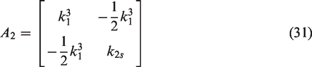
In this paper,

A set of switching-function-like quantities are defined as


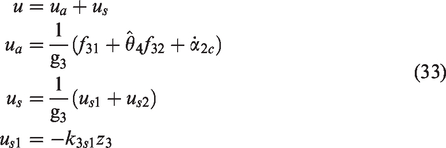
We can develop a virtual control input
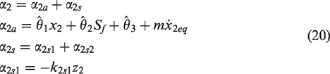
The discrepancy between the control function


According to the equation (21),


The Lyapunov function

The time derivative of
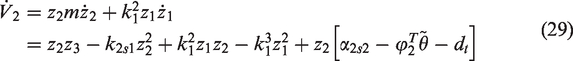
According to the equation (24)

If
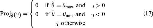
According to the definition of

According to the definition of
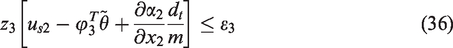
By substituting equation (33) into equation (32), we can get


According to the equation (34),


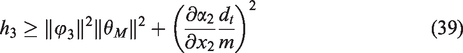
Similar to equations (28)–(30), the stability also can be identified. Therein the matrix
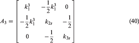
By assigning the parameters
Mechanical–electrical–hydraulic integrated dynamic model of marching tank
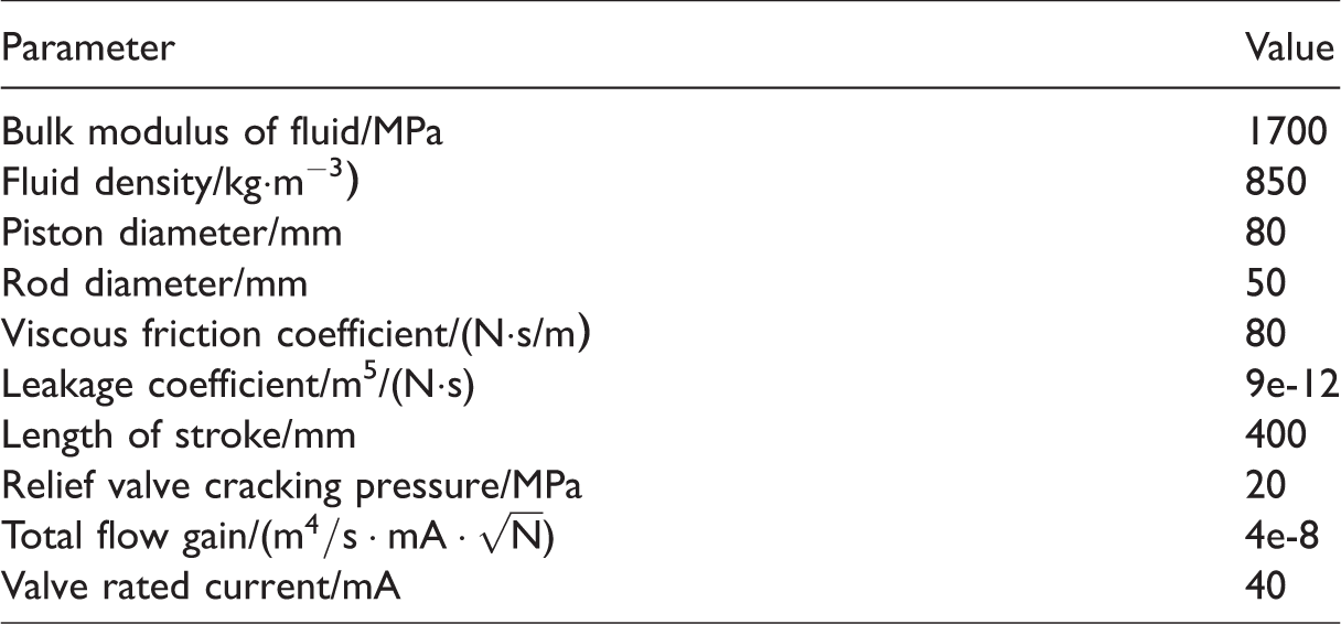
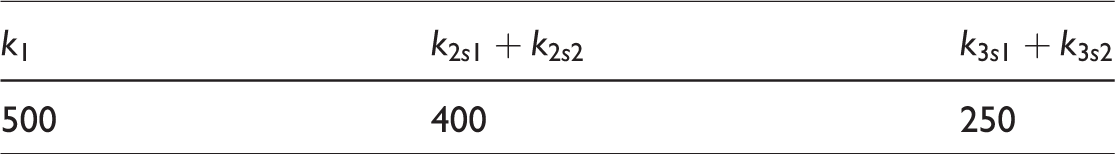
According to the control principle of the vertical stabilizer, the electrohydraulic position servo system model was established in Amesim software with standard hydraulic, mechanical, and signal libraries to calculate the output force of hydraulic cylinder. It mainly consists of hydraulic cylinder, electrohydraulic servo valve, hydraulic pump, motor, accumulator, and fuel tank. The main parameter values of hydraulic servo position system are shown in Table 1.
Parameters value of hydraulic position servo system.
Combining the controller with the established electrohydraulic position servo system model of vertical stabilizer and the dynamic model of tank, a mechanical–electrical–hydraulic integrated dynamic model of marching tank was established. In the dynamic model, the hydraulic cylinder force was simulated by creating an axial force between the piston rod and cylinder and it was calculated by the electrohydraulic position servo system model. The output variables called by the controller program include the elevation angular displacement, velocity and acceleration of hull, the displacement and velocity of piston rod, the pressures in the two chambers of hydraulic cylinder. During the numerical calculation, the sub models are connected through the equation of state, and the data exchange is carried out in each fixed sampling time step. When the sampling time small enough, the system is approximately considered unchanged in a single sampling time. That is, the data exchange is approximately considered to be real time.
In order to verify the established dynamic model of marching tank, the test results in literature 23 were adopted. The vibration response of the hull is verified by real vehicle tests on the typical pavement. The road roughness is similar to the B level road. The vertical vibration acceleration was measured by the acceleration sensor on the first road wheel. During the test, three different gears were chosen, and the speeds corresponded to 14 km/h, 21 km/h, and 31 km/h, respectively. It can be found by comparing the test and simulation results, the peak frequencies of test and simulation date of the second gear were 27.8 Hz and 24.8 Hz, respectively and the error was 10.79%. The peak frequencies of test and simulation date of the third gear were 41.3 Hz and 38.8 Hz, respectively and the error was 6.05%. The peak frequencies of test and simulation date of the fourth gear were 61.6 Hz and 56.0 Hz, respectively and the error was 9.01%. The peak frequencies of the simulation and test were basically the same. With the increasing of speed, the peak frequency increases and the tendency is similar. It verified the rationality and credibility of the established mechanical–electrical–hydraulic integrated dynamic model of marching tank.
Simulation and analysis
Stabilization accuracy
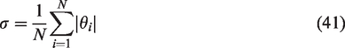
1
is a major index related with the performance of stabilizer. It refers to the arithmetic mean of the swinging amplitude of marching tank gun and can be expressed as
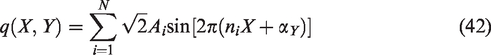
In the dynamic model, road roughness is the main factor causing hull vibration of marching tank. In order to analysis the performance of the designed vertical stabilizer controller, the three-dimensional road roughness model of D level road was reconstructed by using the harmonic superposition method.24,25 The random process of the three-dimensional road can be represented as
Stability analysis of controller
The transient process of the system is concerned with the controller parameters. From the performance analysis of the adaptive robust controller in the literature, 5 better tracking performance can be easily obtained by increasing the controller gain. However, large controller parameters may cause the higher gain feedback of system. Some of the assumptions when designing the controller may be destroyed. Obviously, the conclusion is not always correct at this time. In the process of dynamics calculation, the high controller gain caused a high frequency vibration of the gun system and the vertical stabilizer cannot control the vertical vibration of gun effectively. Therefore, the tracking accuracy of the actual vertical stabilizer cannot be simply improved by increasing the gain of the controller. It indirectly indicates that it is not accurate to design the vertical stabilizer controller based on an approximate transfer function of the tank mechanical system. After several trial calculations, the final control parameters are shown in Table 2.
Controller typical parameters.
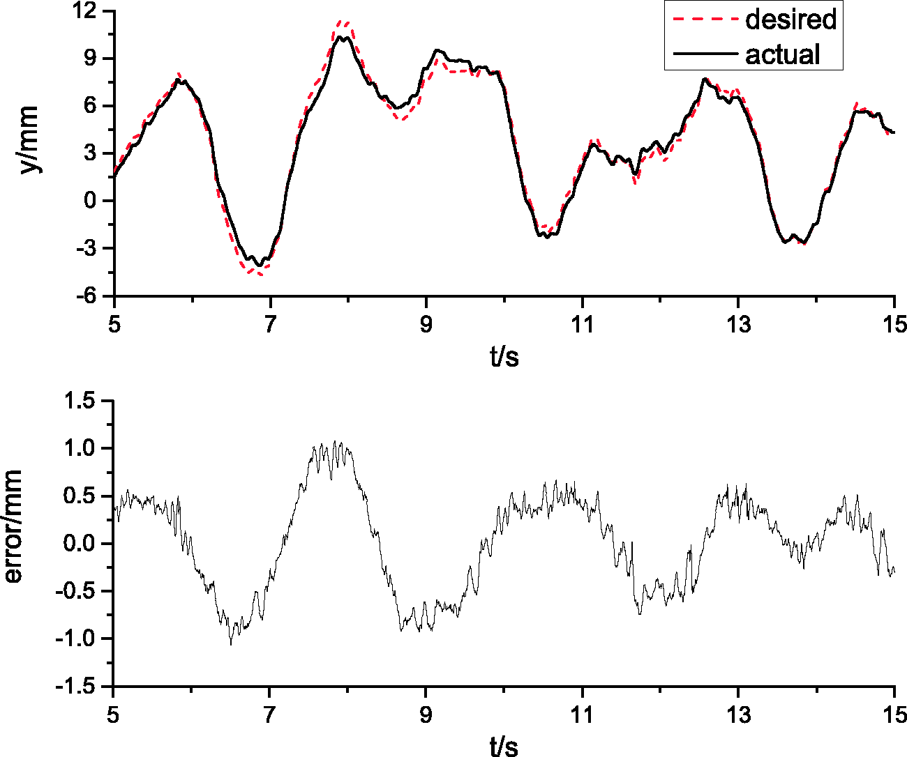
As a position servo system, the vertical stabilizer controls the gun through the movement of piston rod. The tracking error of the adaptive robust controller is shown in Figure 5. It can be seen from the figure that, due to the effect of the adaptive rate, the actual displacement of the hydraulic rod can effectively track the expected displacement during the whole process of tank moving. The tracking error is small and the extreme value is only 1.03 mm. It meets the design requirement of vertical stabilizer.
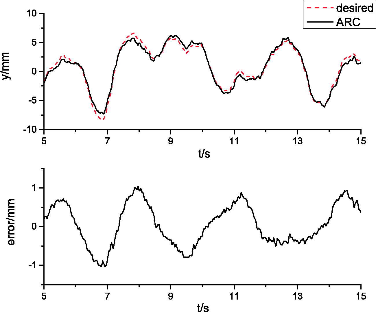
The tracking error of ARC.
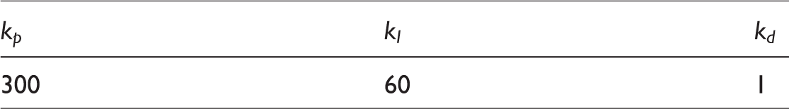
In order to verify the performance of the designed adaptive robust controller, the traditional PID controller was introduced. To ensure the fairness of comparison, the parameters of the PID controller were set to make sure that the controller works on the optimal control parameters as far as possible. The control parameters of PID controller selected in the paper are shown in Table 3. The tracking error of PID is shown in Figure 6, and the extreme value is about 3.79 mm. By comparing the steady-state errors of the two controllers, the tracking error of the adaptive robust controller is smaller than the value of PID controller, and the extreme value reduces 56.99%. Furthermore, according to Figure 7, the piston rod velocity can also track the desired value effectively with the adaptive robust controller. It further demonstrates the robust performance of the adaptive robust controller.
Controller typical parameters of PID.
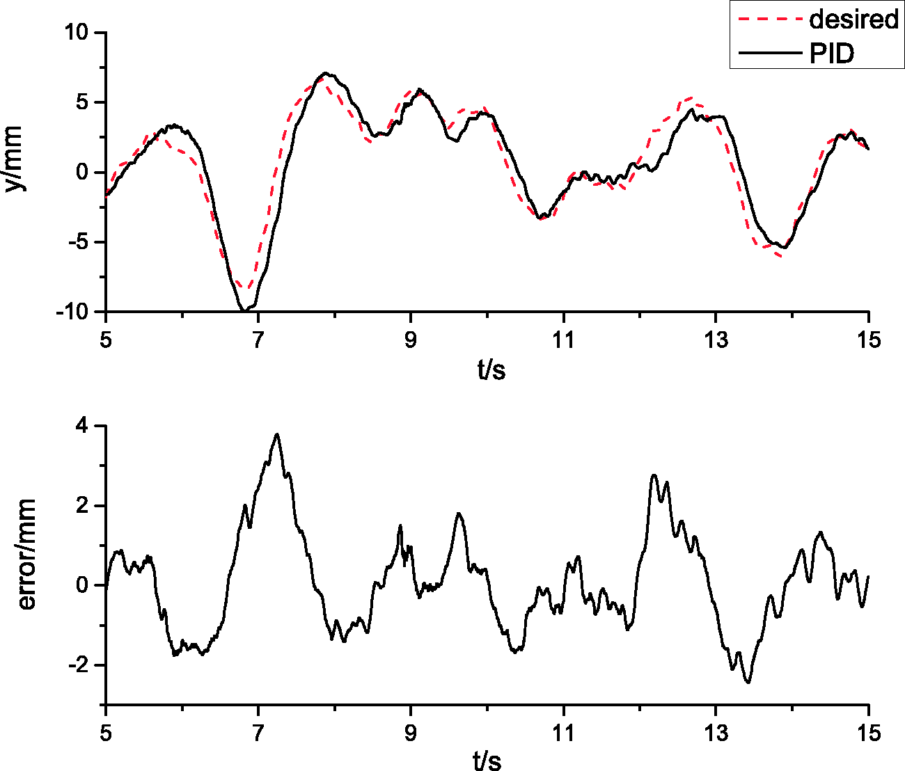
The tracking error of PID.
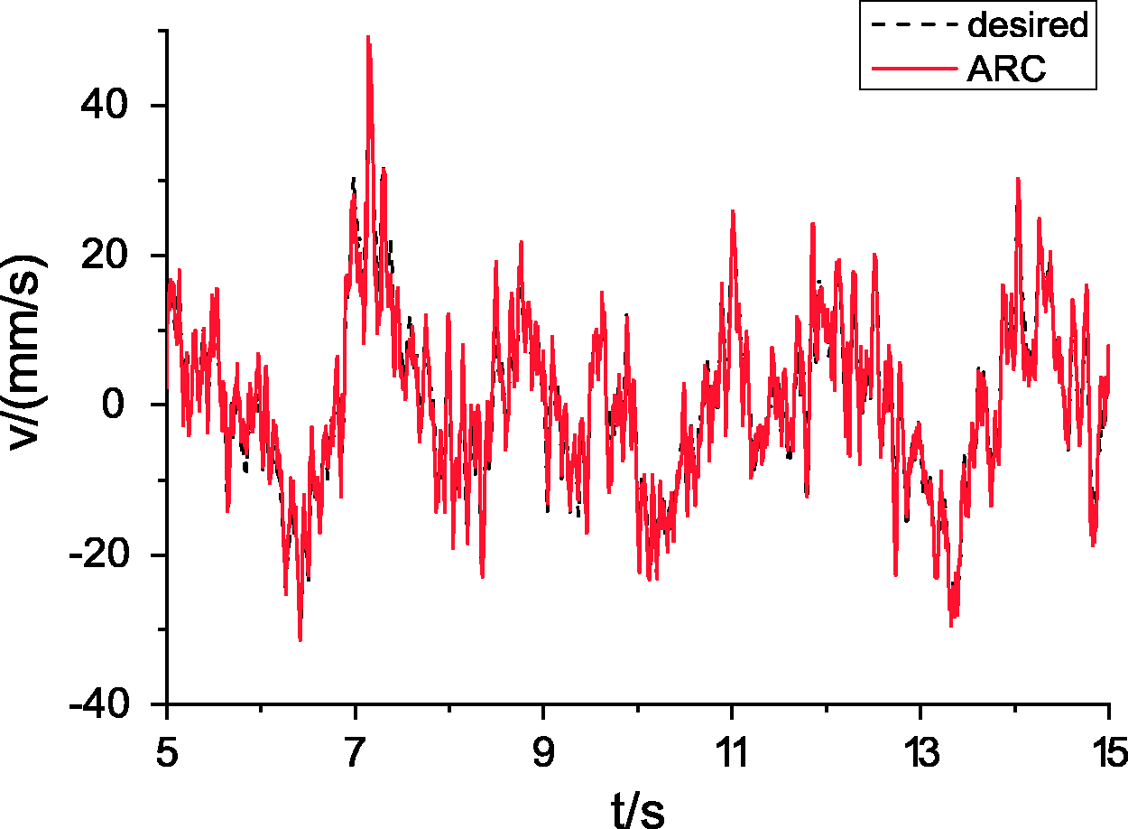
The velocity of the piston rod of ARC.
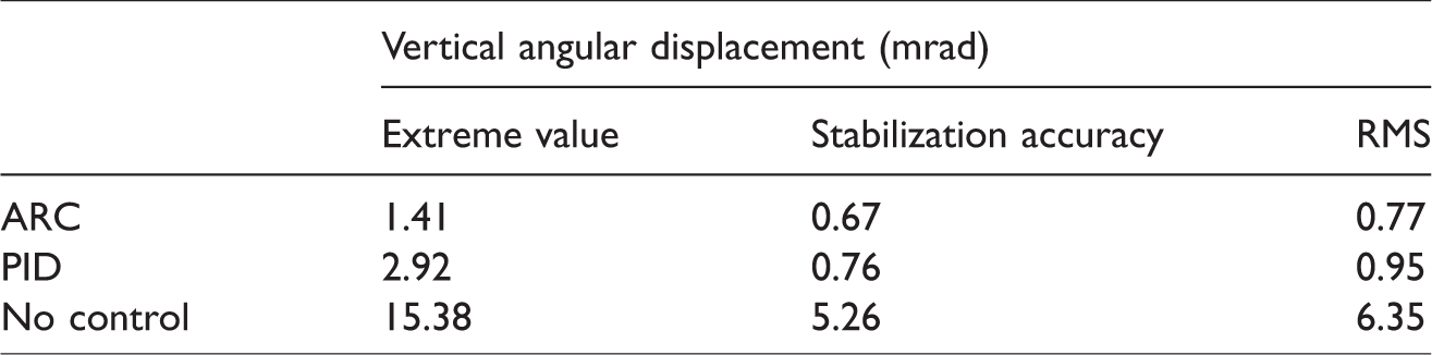
The vertical vibration of the gun can be characterized by the cradle elevation angular displacement when the nonlinear factors of the gun are not taken into account. The comparison between the cradle elevation angular displacements with two different controllers is shown in Table 4 and Figure 8. The cradle elevation angular displacements of marching tank are controlled effectively by these two controllers. From the literature, 27 the target distance deviation caused by the fire angle deviation because of the vertical angular vibration of hull is 3–5 times greater than that caused by the projectile horizontal velocity. Table 4 shows that the cradle vertical amplitude of marching tank without control is large, and the extreme value is 15.38 mrad. Under such conditions, the firing accuracy is difficult to meet the requirement.
Cradle vertical angular displacement.
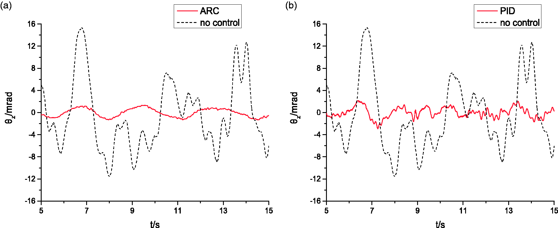
The cradle elevation angular displacement. (a) ARC and (b) PID control.
Under the control of the adaptive robust controller, the extreme value of cradle elevation angular displacement decreases to 1.41 mrad and the stabilization accuracy is 0.67 mrad. Under the control of the PID controller, the extreme value of cradle elevation angular displacement decreases to 2.92 mrad and the stabilization accuracy is 0.76 mrad. In literature, 1 the vertical stabilization accuracy of tanks driving on a standard medium rolling road with a moderate speed (20–25 km/h) is about 0.5–1.0 mil (about 0.52–1.05mrad). The two controllers can both satisfy the requirement of actual vertical stabilization accuracy. The control method is feasible and the established mechanical–electrical–hydraulic integrated dynamic model is correct and credible.
Compared with the PID controller, the stability accuracy of the marching tank is improved by 11.84% under the action of the adaptive robust controller. The extreme value of the elevation angular displacement decreases by 51.72% and the Root Mean Square (RMS) decreases by 18.94%. In addition, from Figure 8, the elevation angular displacement curve under the control of the adaptive robust controller is smoother. Obviously, the adaptive robust controller has better stabilizing effect.
Nonlinear factors analysis
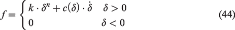
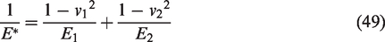
In the actual driving process of tank, the muzzle vibration is different from that at the cradle due to the nonlinear factors such as the flexibility of the rear-seat components and the collision between components. In this paper, the following nonlinear factors were considered: the barrel flexibility, the contact between the barrel and the bushing, the contact between the trunnion and the bearing.28,29 The finite element model of the barrel was established in Hypermesh and it was discretized by isoparametric hexahedral elements. The modal neutral file of the barrel was obtained by the modal analysis based on the modal reduction method. The flexible barrel model was established using the modal neutral file, which was connected to the breech ring with the interface node in the model. The contact forces were calculated by the user subroutines, which were inserted with application programming interface. The normal contact force f between the barrel and the bushing was calculated by the nonlinear spring damping model and it can be written as

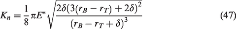
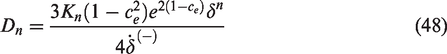
The contact force between the trunnion and bearing was calculated by the revolution clearance joint model,
30
and it can be written as

The first term on the right side of equation (46) represents the elastic deformation force during the collision, and the second term represents the damping force during the collision, in which
The muzzle elevation angular displacements under the control of two kinds of controllers are shown in Figure 9. The barrel bends downward when tank moving with a low speed on a flat road because of the barrel flexibility. It causes the muzzle angular displacement smaller than the value of cradle. But the waveforms of the two different elevation angular displacement curves are almost accordant. It demonstrates that the excitation receiving from the random road is the main factor influencing the vibrations of muzzle and cradle when the tank drives at a low speed. However, the vibration frequency of muzzle is higher than that of cradle because of the nonlinear factors of gun. In addition, we can also find that the muzzle vertical vibration amplitude is greater under the control of PID controller and it has higher frequency vibration components. Then, the frequency of the gun passing the shooting gate under the control of PID controller is higher compared with that under the control of adaptive robust controller. As a result, the gun passes the shooting gate at a high speed. Obviously, it is not conducive to ensure the firing accuracy of tank firing on the move.
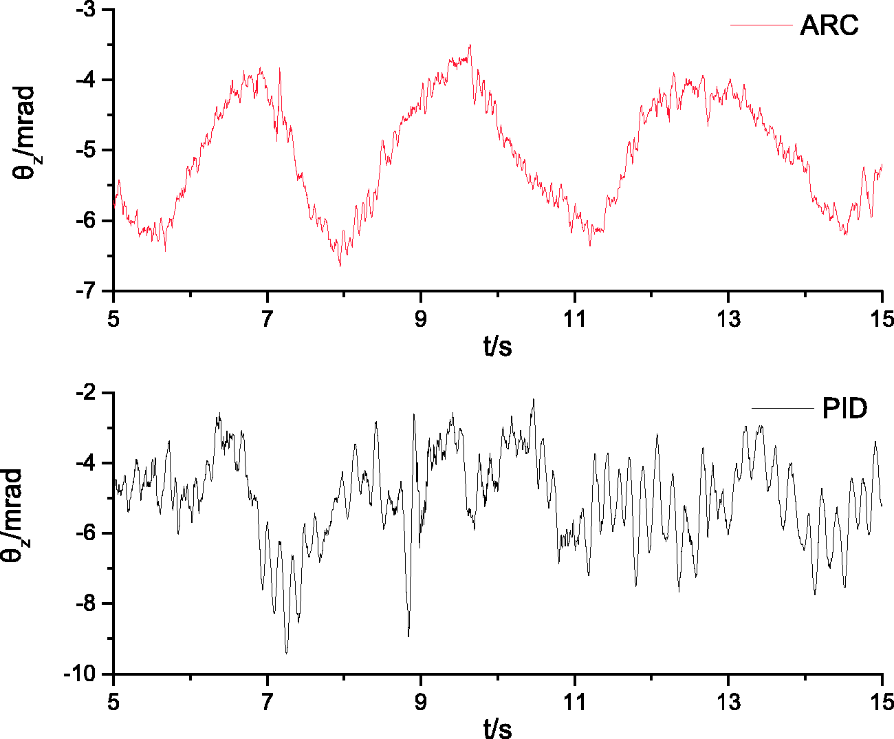
The muzzle elevation angular displacement.
Figure 10 is the power spectrum density curve of the muzzle elevation angular acceleration obtained by fast Fourier transform. Due to the filtering of the track for road excitation, the upper frequency of road input is limited. The dynamic response of the muzzle is mainly distributed below 100 Hz, 31 and the vibration energy of the part greater than 100 Hz is small. So frequency range between 0 and 100 Hz is analyzed.
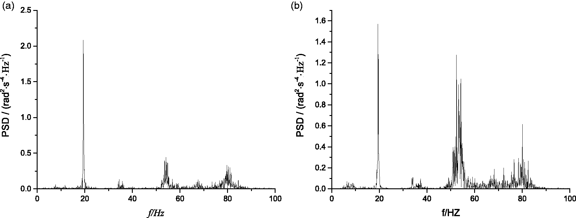
The power spectrum density curve of the muzzle elevation angular acceleration. (a) ARC and (b) PID control.
As shown in Figure 10, the muzzle vibration energy of marching tank is mainly distributed around 20 Hz, 35 Hz, 52 Hz, and 80 Hz and the vibration energy at the low-frequency component around 20 Hz is the largest. Comparing with the value under the control of PID controller, the vibration energy at the low-frequency component around 20 Hz under the control of adaptive robust controller is bigger. The vibration energy at the high-frequency component around 52 Hz and 80 Hz is smaller obviously.
Through the above analysis, we can found that the vertical stabilizer controller designed by the adaptive robust control method had better comprehensive stability when comparing with the traditional PID control. However, some nonlinear factors of the gun system will seriously influence the desired muzzle stabilization accuracy of the vertical stabilizer. It is not conducive to improve the firing accuracy of marching tank, and more in-depth studies are needed.
In addition, these nonlinear factors have great influence on the tracking performance of the control system. The tracking error of ARC without considering the collisions between components is shown in Figure 11. The contact between the barrel and the bushing, the contact between the trunnion and the bearing were replaced by the translational joint and revolute joint. The control law and the controller parameters were the same as above. From Figure 11, the tracking error is greatly reduced without considering the collisions between components, and the extreme value is only 0.54 mm. The cradle stabilization accuracy is 0.31 mrad and the extreme value of elevation angular displacement is only 0.85 mrad. Through the comparison in Figure 5, the curve of piston rod displacement tracking error is smoother. The collisions between components have a detrimental effect on the tracking performance of control system. The gun system and the vertical stabilizer control system are mutually coupled. It is not accurate to simplify the tank dynamics model as a linear transfer function. The high stabilization accuracy based on that assumption is difficult to get in practice due to the limitation of mechanical system.
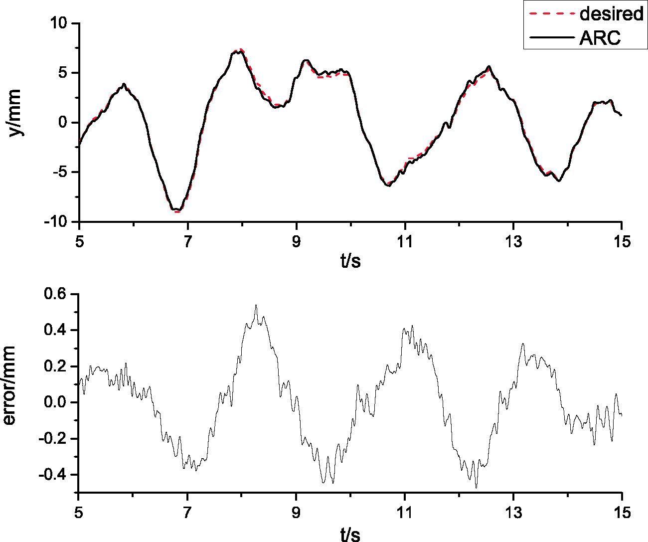
The tracking error of ARC without considering the collisions between components.
Modeling and analysis of muzzle error compensation signal
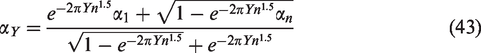
From the above analysis, though the vertical stabilizer worked efficiently, the muzzle vertical vibration was still overall greater than the value of cradle. It was because the desired displacement of piston rod calculated according to equations (8) and (9) ignored the nonlinear factors of gun system such as the barrel flexibility. In fact the cradle and muzzle vibrations were thought as the same during designing the vertical stabilizer. The angle and angular velocity gyroscope providing control input to the control system are both installed on the cradle, and the stabilization goal is cradle. In order to decrease the muzzle vibration of marching tank, the muzzle error compensation signal was added into the designed controller, thus, the calculation formula of the desired displacement of the piston rod can be expressed as


The tracking error of adaptive robust controller with muzzle error compensation signal.
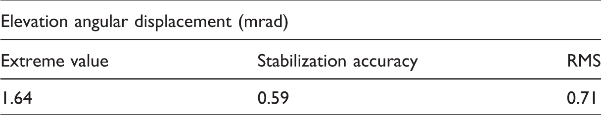
The muzzle elevation angular displacement with muzzle error compensation signal is shown in Figure 13. The muzzle vibrates near the sighting angle. As shown in Table 5, the muzzle elevation angular displacement is small with an extreme value of 1.64 mrad and the muzzle stabilization accuracy is 0.64 mrad. Comparing with Figure 9, the muzzle vertical vibration is smaller than the value before adding the muzzle error compensation signal. The detrimental effect of the nonlinear factors of gun system on muzzle vibration is controlled. So the method of adding the muzzle error compensation signal in the designed adaptive robust controller is feasible and effective.
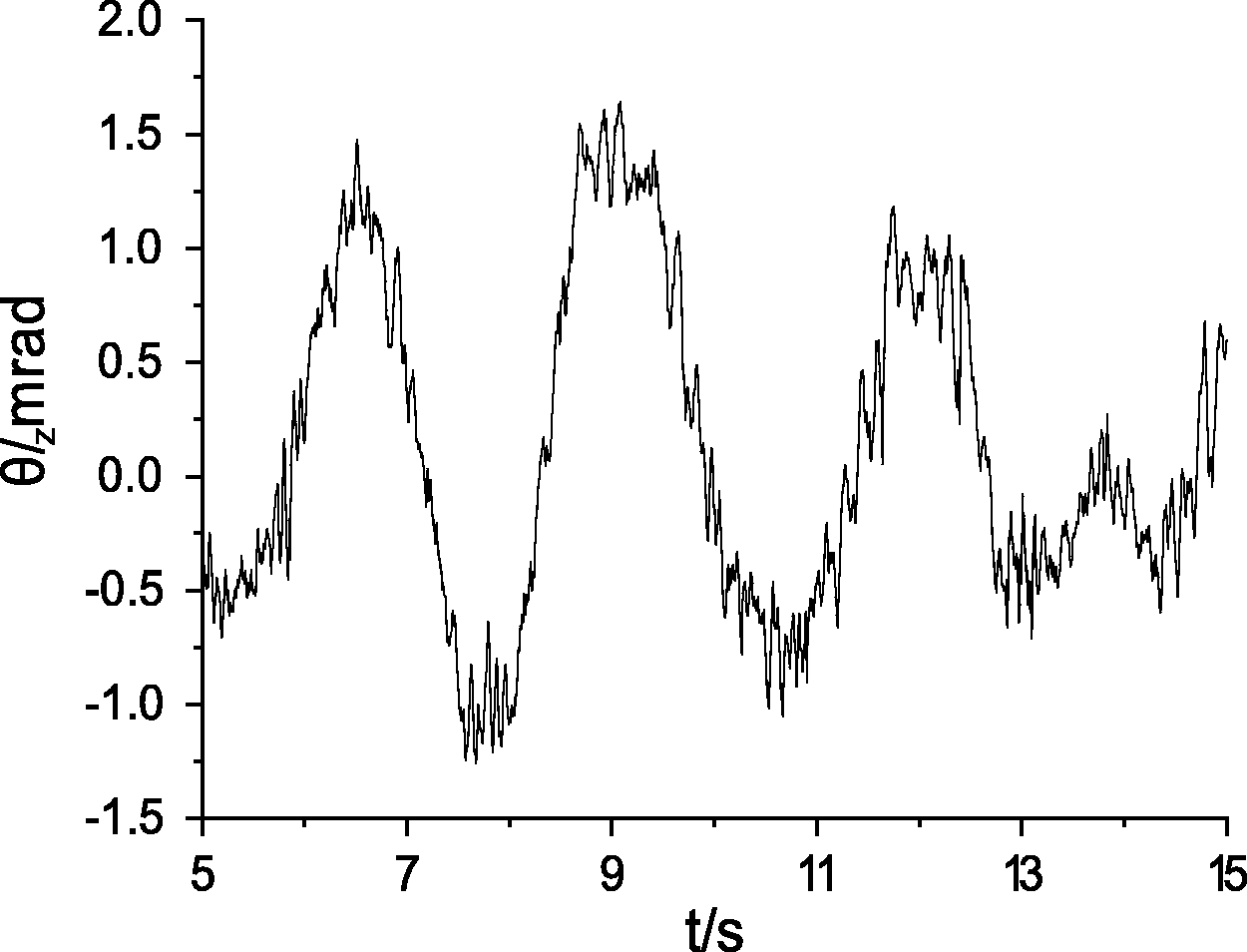
The muzzle elevation angular displacement with muzzle error compensation signal.
The muzzle elevation angular displacement.
As show in Figure 13, the muzzle elevation angular displacement has more high-frequency component than that of cradle because of the muzzle error compensation signal. This is also reflected in the tracking error in Figure 12. Obviously, it also affects the first-round-hit accuracy of marching tank and it will be the focus of future work.
Conclusions
Achieving high firing accuracy of marching tank is challenging. In order to better understand the dynamic behavior and decrease the muzzle vibration of marching tank, dynamic simulation on vibration control of marching tank gun was conducted. The main contributions and conclusions are as follows:
By comparing with the traditional PID control method, the adaptive robust controller present in the paper had better tracking performance and control effect. The low-frequency components in the muzzle vibration energy were greater. The mechanical, hydraulic, and control subsystems of tank system affect each other. It is not accurate to simplify the tank dynamics model as a linear transfer function in the existing work, and the high stability accuracy obtained based on this is difficult to achieve in practice due to the limitations of the mechanical system. Research about the mechanical–electrical–hydraulic integrated dynamic model of marching tank is valuable and very helpful for the calculation accuracy. By adding the muzzle error compensation signal in the designed controller, the detrimental effect of the nonlinear factors of gun system on muzzle vibration was controlled and the muzzle elevation angular displacement was reduced. The compensation signal had little influence on the tracking error and stability of the controller.
This study provides an approach to decrease the muzzle vibration of marching tank. However, the established model needs to be verified with more test values. In addition, the controller designed in the paper ignored the flexibility, clearance, and some other nonlinear factors of gun system, and it is the focus of the follow-up study. The projectile–barrel coupling problem of marching tank and the calculation of impact point based on the exterior ballistics can be carried out on this basis.
Footnotes
Declaration of conflicting interests
The author(s) declared no potential conflicts of interest with respect to the research, authorship, and/or publication of this article.
Funding
The author(s) disclosed receipt of the followings financial support for the research, authorship, and/or publication of this article: This work was supported by the National Natural Science Foundation of China [Grant No. 11572158, 51705253].