
Abstract
Structural health monitoring has become increasingly important in the effective evaluation of structural health conditions and the maintenance service of structures. The validity and convenience of obtaining sensor data are critical for data mining, feature extraction, and condition assessment. A fast wireless low-frequency vibration inspection system (FWLVIS) based on wireless sensor networks for offshore platform structural vibration inspection is presented in this paper. The designed system consists of intelligent acquisition equipment and eight wireless nodes with low-frequency acceleration sensors, while the entire system has 64 collection channels. The wireless nodes integrated with a vibration sensing unit, an embedded low-power micro-processing unit, a wireless transceiver unit, and a large-capacity power unit perform functions, which could perform data collection, initial analysis, data storage, and wireless transmission. The intelligent acquisition equipment integrated with a high-performance computation unit, a wireless transceiver unit, a mobile power source, and the embedded data analysis software could completely control the multi-wireless nodes, receive and analyze the data, and implement the parameter identification. Experiments are performed on a single pendulum, and then on an offshore platform model is constructed to verify the FWLVIS. The experimental results show that the system has the following characteristics: fast arrangement, high sampling rate, high resolution, and capacity for low-frequency inspection. Thus, the system has good application prospects and practical value in the field of structural health monitoring and non-destructive inspection.
Keywords
Introduction
The large offshore platforms have been used to develop ocean oil and gas resources for decades, even centuries. Under the long-term effects of environmental erosion, the aging and loading of materials as well as coupling of disasters, such as the fatigue effects and sudden change, could cause damage accumulation and decay resistance in the structure and system.1,2 The inspection and monitoring of offshore platform structure generally involve artificial non-destructive inspection and wire acquisition,3–5 which require special test equipment and professional personnel, so this inspection method is inconvenient and expensive. Compared with the general method mentioned above, the non-destructive inspection technology based on vibration testing is simpler and less expensive.6,7 During the vibration testing, various parameters are collected by sensors, and then the data are processed with an intelligent algorithm, which could determine the status of offshore platform and give the appropriate measures.8–10 The information of sensor is generally transmitted by wires. However, the wire acquisition system for offshore platforms utilizes numerous wires and makes the cabling very difficult. The large number of wires makes the identification of broken wire difficult and results in high maintenance costs. A large amount of manpower and capital are also consumed during cabling. These issues cause problems in the practical application. The development of wireless sensor network technology is accompanied by the development of sensor technology, wireless communication technology, and MEMS technology. The application of wireless sensor networks in structural inspection is a current challenge. Compared with the wire sensor technology, the wireless sensor technology could avoid the huge consumption of wires and high maintenance costs. To address such issue, a fast wireless low-frequency vibration inspection system (FWLVIS) is designed and validated in this study.
System architecture
The system architecture of FWLVIS is shown in Figure 1. The designed system includes a piece of intelligence acquisition equipment and eight wireless collection nodes. The system has 64 sampling channels, that is, every wireless collection node has eight 20-bit A/D channels. The data are transmitted in a 2.4 GHz wireless channel, and every sensing data channel in charge of data transmission is within a stable frequency band.
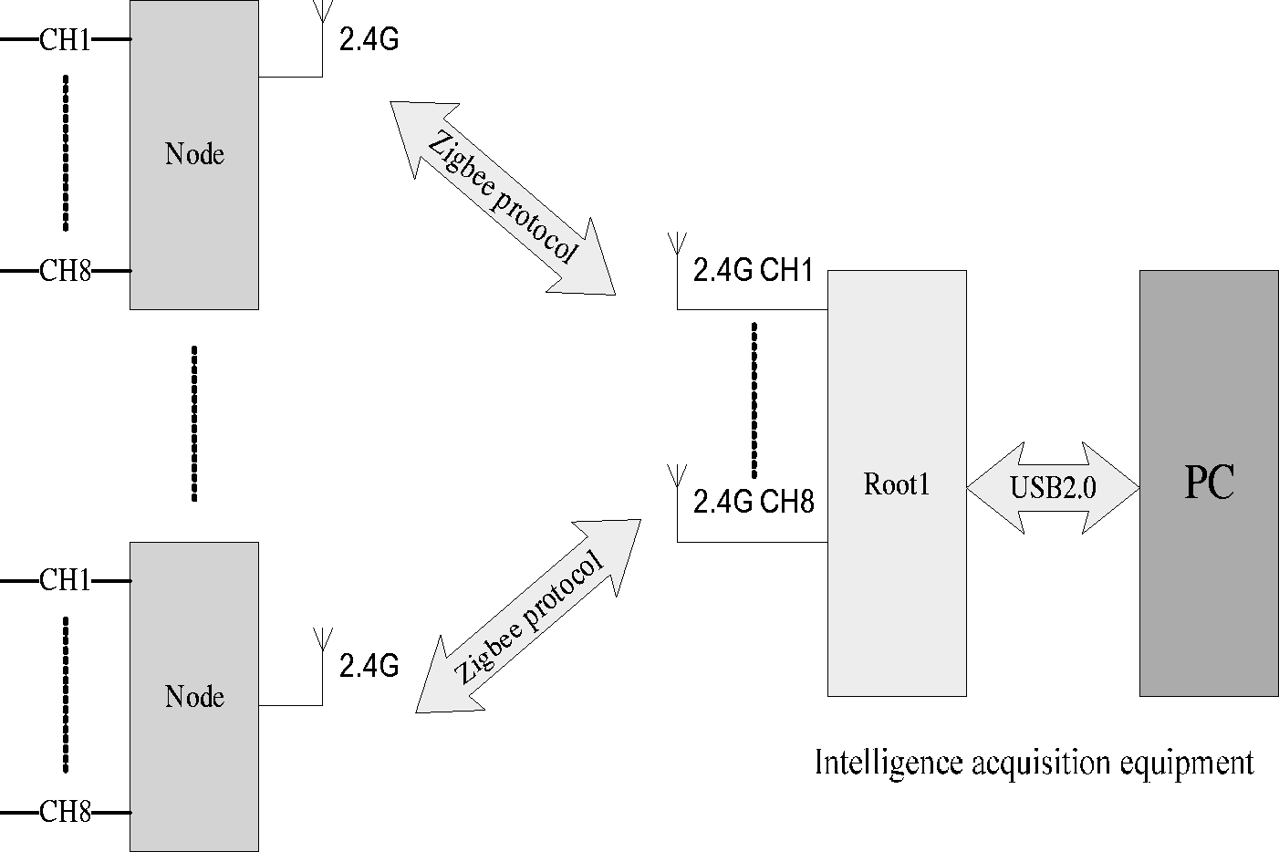
System structure.
Design of low-frequency wireless acceleration sensor
Previous studies have shown that the safety assessment of offshore platform based on modal information is possible by performing the global dynamic inspection of platform regularly.11,12 The structural global inspection technology for offshore platforms can overcome the limitations of local inspection. The global inspection technology could verify the design assumptions, monitor the construction quality, and implement the real-time safety status assessments. Moreover, this technology could operate without external auxiliary excitation. Global inspection technology, which is an indispensable technical means, therefore has significant advantages. The structure of low-frequency wireless acceleration sensor is shown in Figure 2. The modular wireless acceleration sensor node consists of a low-frequency acceleration sensor unit, a modulated unit, a microprocessor, a storage unit, a wireless transceiver unit, and a power management unit.13–16
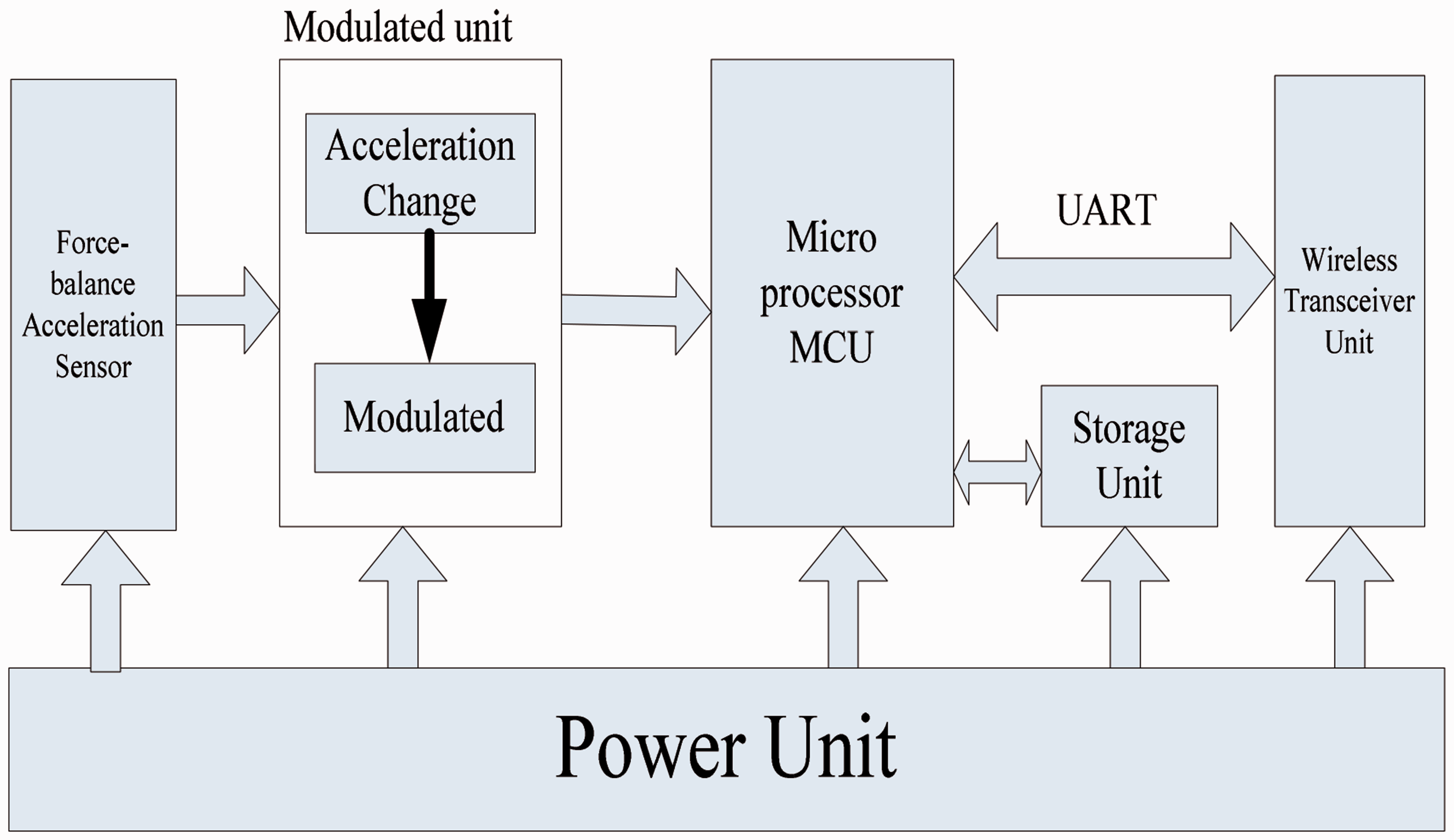
Structure of the ultra-low-frequency wireless acceleration sensor.
Sensor unit
A kind of force-balance sensor was used in this study as a vibration measurement unit. The force-balance sensor with a closed-loop structure could convert the data to force or moment and then adjust the system balance with feedback force. This type of sensor with its huge dynamic range and high measurement precision is used in low frequency and low-g measurement, which is also a crucial unit in the inertial navigation systems. Therefore, it can match the requirements of low-frequency vibration measurement for offshore platform structures due to its good performance and ultra-low frequency.
Modulated unit
The wireless nodes were employed to provide the support to force-balance acceleration sensor that requires a ±12 V power supply and generates a ± 5 V voltage signal. The wireless nodes are equipped with a multi-way switch chip (MAX4051) to perform eight-channel selection and a 24-bit highly accurate ADC chip (ADS1248) to convert the analog signal to digital signal. The ADC system could generate ±2.5 V and ±5 V power supply through LM4040A to generate all types of power supplies.
Microprocessor and storage unit
The microprocessor employs TI high-performance 16-bit MSP430F5438. The serial microprocessor has extremely low operating power consumption, and the performance is up to 25 MIPS at 1.8 V to 3.6 V operating voltage range. Meanwhile, it could satisfy the design requirements of wireless sensors with low power consumption and high rapid data processing. The storage unit is equipped with NAND large capacity flash memory.
Wireless transceiver unit
The wireless transceiver unit for wireless data transmission consists of Zigbee wireless chip CC2520 and enlarged front CC2591. The CC2520 chip is a 2.4 GHz license-free ISM band (ZigBee/IEEE 802.15.4), which is the second-generation RF transceiver from TI Company. The CC2591 is a 2.4 GHz RF front end unit for low power consumption. The low voltage wireless application can improve the transmission power and the receiving sensitivity, which could also increase the wireless signal strength and transmission distance.
Power unit
In the designed system, a 24 V battery was selected as the wireless node’s power source for rapid measurement and continuous power supply. The energy design has a two-stage transformation structure with the reason of that each unit in the system requires different power supplies, such as ±12 V and 3.3 V, and the analog circuits require a high-voltage ripple. The first stage involves the use of DC/DC chips for the transformation from 24 V to ± 15 and 3.3 V. The second stage involves the use of LDO chips 7812 and 7912 for the transformation from ±15 V to ±12 V.
The wireless node, shown in Figure 3, was integrated with the abovementioned units.
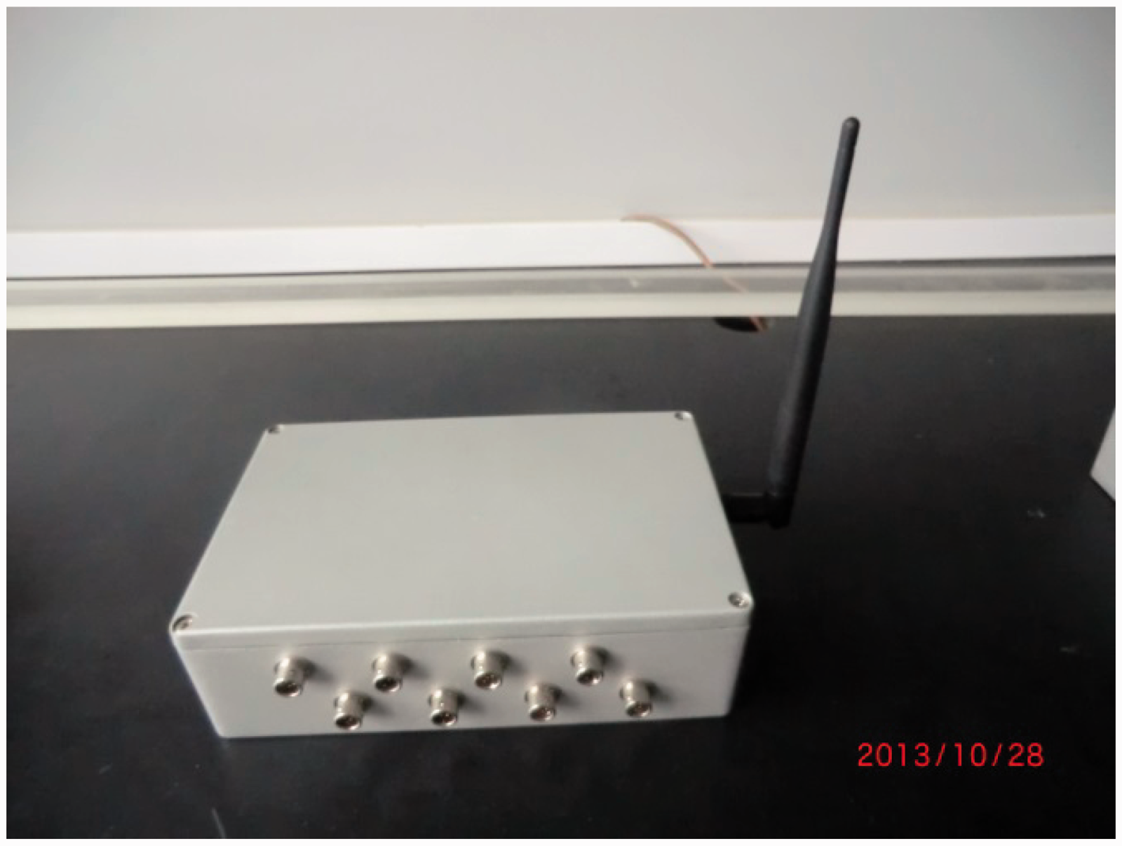
Wireless sensor node.
Software design of wireless low-frequency vibration acquisition system
The software of wireless low-frequency vibration acquisition system consists of two parts: an embedded program for the wireless nodes and the host PC acquisition software.
Embedded program for wireless nodes
The embedded program integrated with an ADC driver, a storage driver, a wireless driver, preliminary data analysis, and diagnosis. It could control circuits, receive commands from the host for parameter setting, and implement data acquisition, processing, storage, and transmission.
The workflow of every wireless node is shown as follows: the wireless node, powered up in the wireless receiving state, does not operate until the command from the host is received. During acquisition process, the host implements parameter setting in all of the wireless nodes and then sends a start or stop command to control the data acquisition. The wireless node collects the vibration data of offshore platform for inspection.
Host acquisition software
After completing the parameter setting in the wireless nodes, the host acquisition software performs data collection, data export, data storage, and data analysis and processing. The modular design consists of basic settings, real-time waveform monitoring, history waveform playback, data export, help documents, and other modules. The acquisition software’s modules are shown in Figure 4.
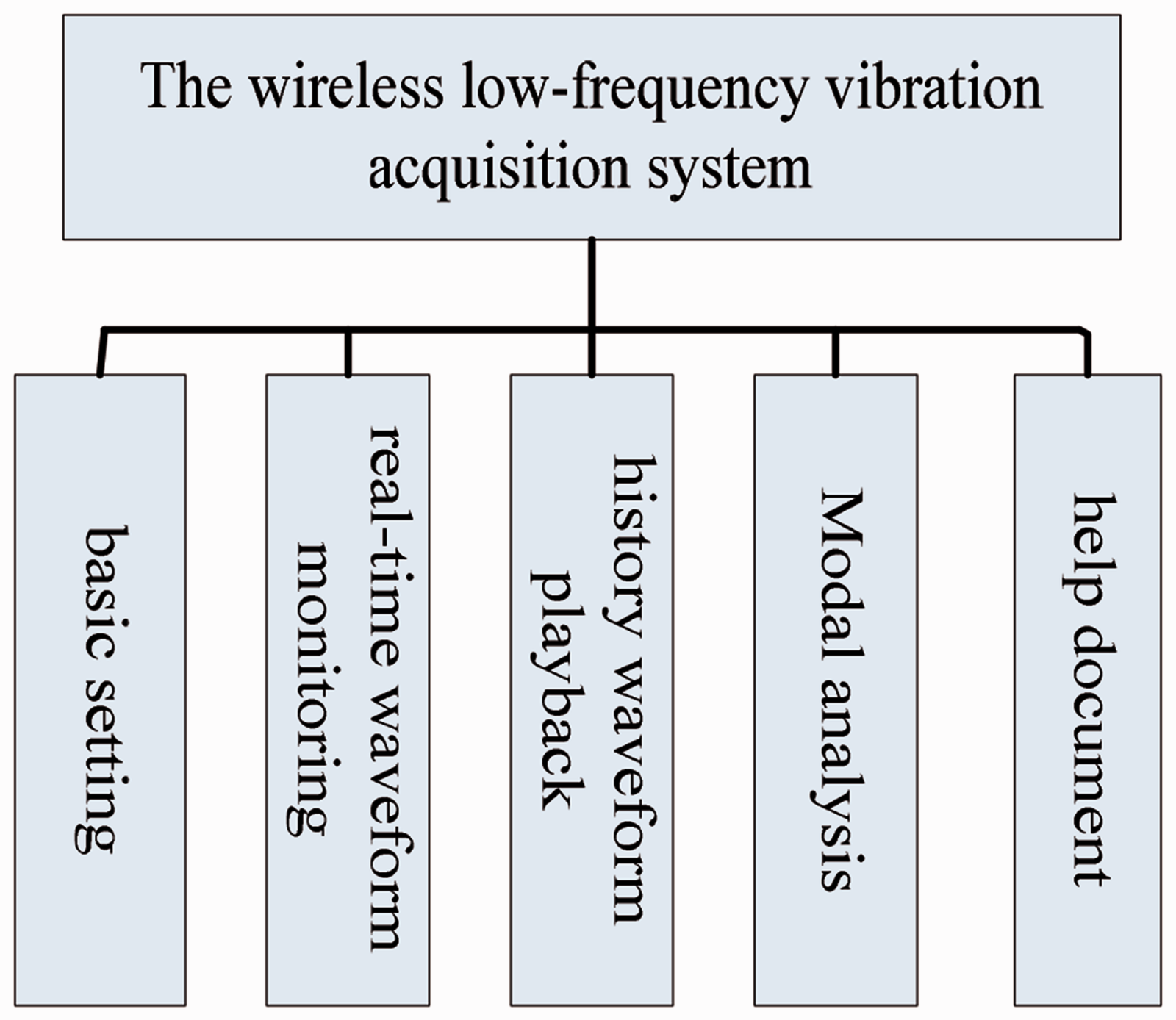
Modules of the host acquisition software.
The basic settings were used to set the state of wireless nodes, wireless transmission channels, sampling frequency, file storage path, and other parameters. The real-time waveform monitoring displays the real-time waveform of collected data and writes the data into the database. The history waveform playback provides a playback of the history waveform based on the data collected to facilitate analysis. The modal analysis could conduct simple data analysis of special structures. The help document provides the information for users who utilize the acquisition software.
Experiments and data analysis
Experiment on a single pendulum using FWLVIS
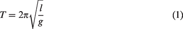
An experiment on a single pendulum was performed to verify the designed wireless low-frequency acceleration sensor. The pendulum is a simple low-frequency vibration measurement experimental device. As the pendulum swings in a small period based on equation (1), the vibration cycle and the corresponding vibration frequency are not similar when the pendulum lengths are different. Therefore, the low-frequency vibration signals can be produced as long as the length of pendulum is controlled in the horizontal direction.
The force-balance accelerometer connected with a wireless node and the piezoelectric accelerometer connected with wire NI equipment were fixed on the hanging baskets of a single pendulum with strong magnets. The experimental system diagram and sensor layout are shown in Figure 5.
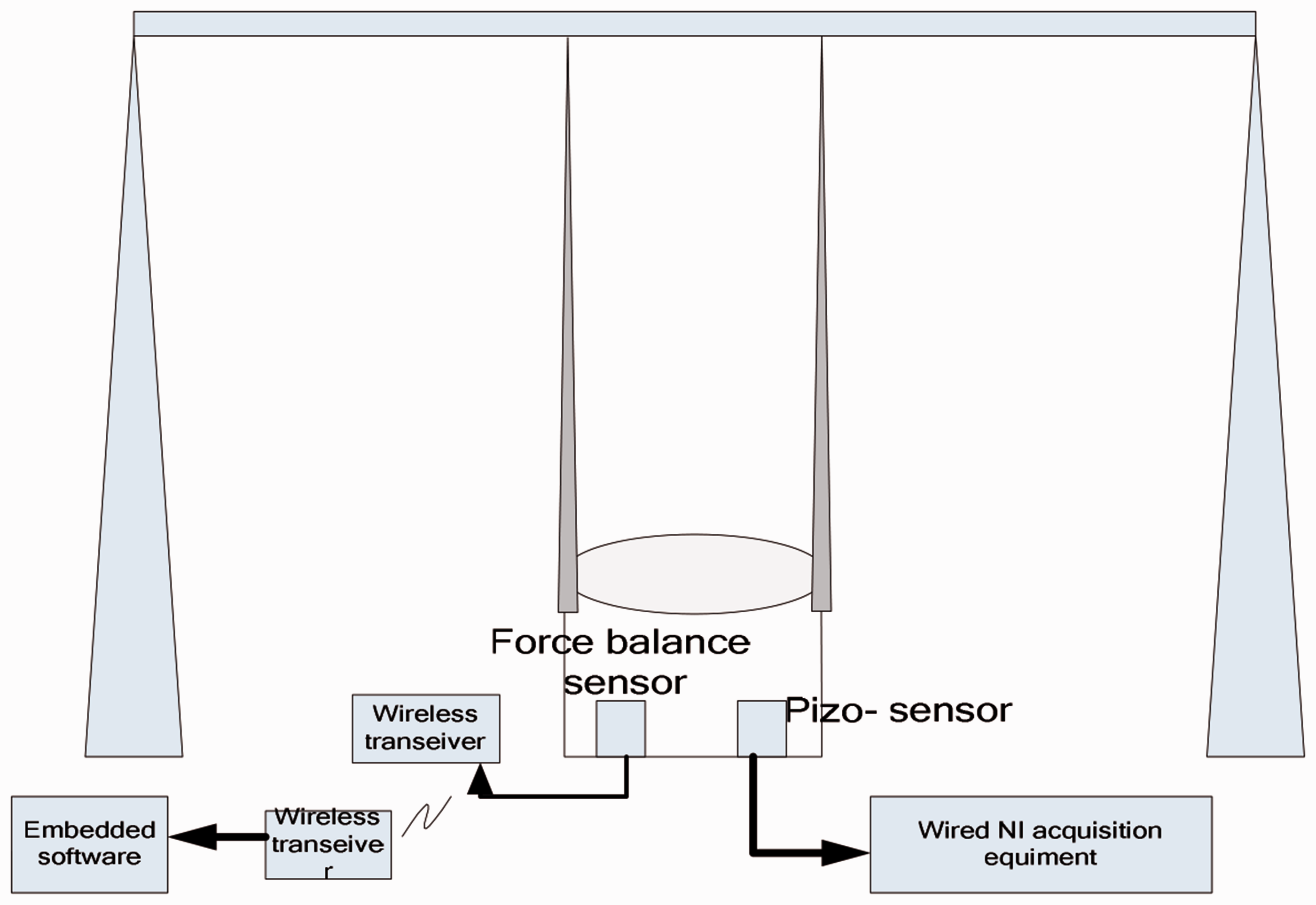
Horizontal vibration experiment.
During the test, the pendulum was controlled into damping vibration status with the swing angle (<5°) and the small vibration amplitude on the horizontal plane. The sample rate of FWLVIS and the wire NI acquisition system was set to 100 Hz. The acceleration data collected at the lengths of pendulum are 0.9 and 2.2 m, respectively.
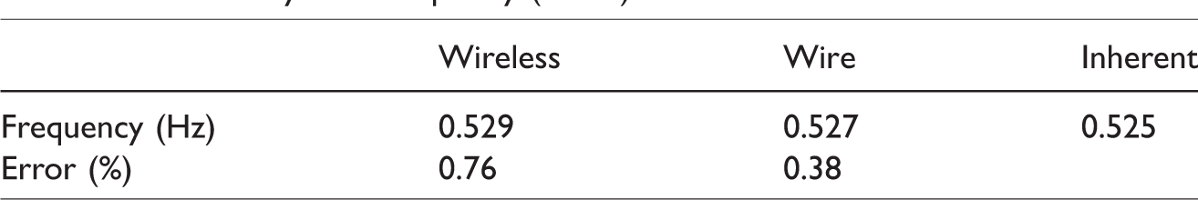
The vibration signals of using wireless and wire, and the corresponding frequency analyses when the lengths of pendulum are 0.9 and 2.2 m are shown in Figures 6 and 7, respectively. The time analysis of vibration signals when the lengths of pendulum are 0.9 and 2.2 m indicates that the wireless and wire time-domain waveform are basically consistent. The relative error among wireless, wire, and inherent frequencies is very small, as shown in Tables 1 and 2. The experimental results show that the FWLVIS collects acceleration data to reflect the actual low-frequency horizontal vibration, and it is suitable for low-frequency vibration detection.
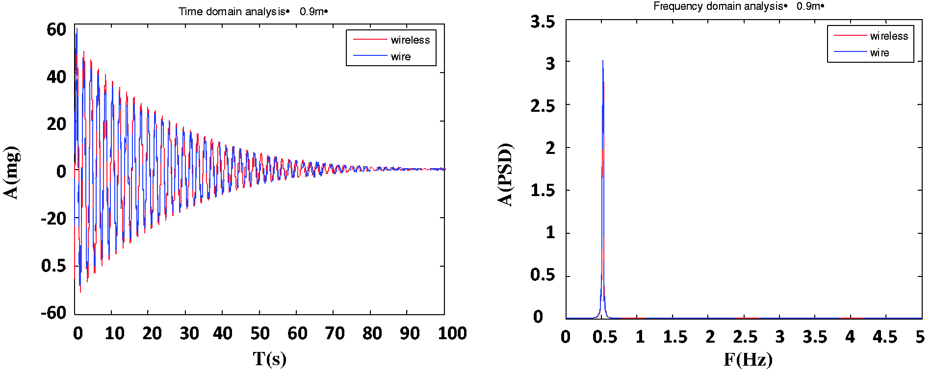
Time and frequency analysis of the pendulum test (0.9 m).

Time and frequency analysis of the pendulum test (2.2 m).
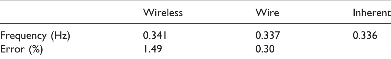
Error analysis of frequency (0.9 m).
Error analysis of frequency (2.2 m).
Vibration test on the offshore platform model knocked using FWLVIS
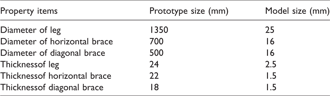
The offshore platforms operating in the harsh marine environments are subject to various loads. The effect of sea ice is significant and it could cause damage to the structure of offshore platforms. The vibration test was performed on an offshore platform structure model in this study to verify the designed FWLVIS. The main structural parameters of offshore platform are listed in Table 3. The effect of sea ice was simulated by the knock test. The offshore platform model shares similarities with the actual one in terms of natural frequency, height, strength, and others. The finite element model of offshore platform using ANSYS and the actual physical models are shown in Figure 8.
Main structural parameters.
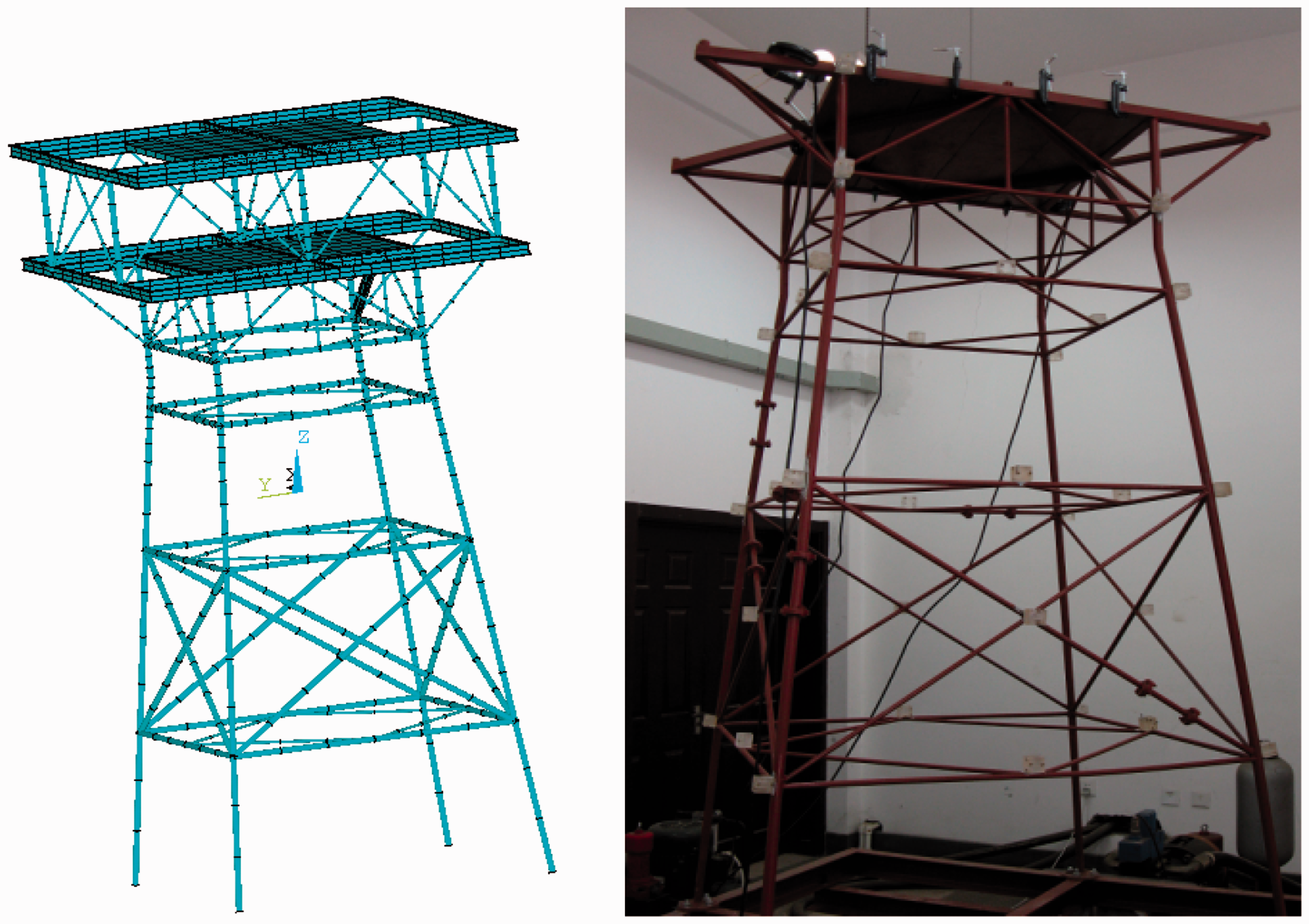
Finite element and actual models of the offshore platform.
The wireless sensor nodes were placed on the two diagonal sections of the offshore platform structure model and tightly fixed with a clamp. The wireless communication unit was built between the nodes and the data collection center, so the several vibration parameters (i.e. the structure’s vibration frequency) were obtained.
In the knock test, a hammer was used to hit the offshore platform structure model in the direction of horizontal force-balance accelerometer to simulate a sea ice bump. The offshore platform structure model generates free damping vibration when subjected with the hammer. The first- and second-order natural frequencies of the structure model were drawn by frequency analysis. When the damage occurs, the two natural frequencies change. Three groups of test data were collected for analysis to minimize the random error. These three conditions of time and frequency domain analysis are shown in Figure 9 and Table 4. The time domain shows a vibration damping waveform, and the frequency domain appears as first- and second-order frequencies.
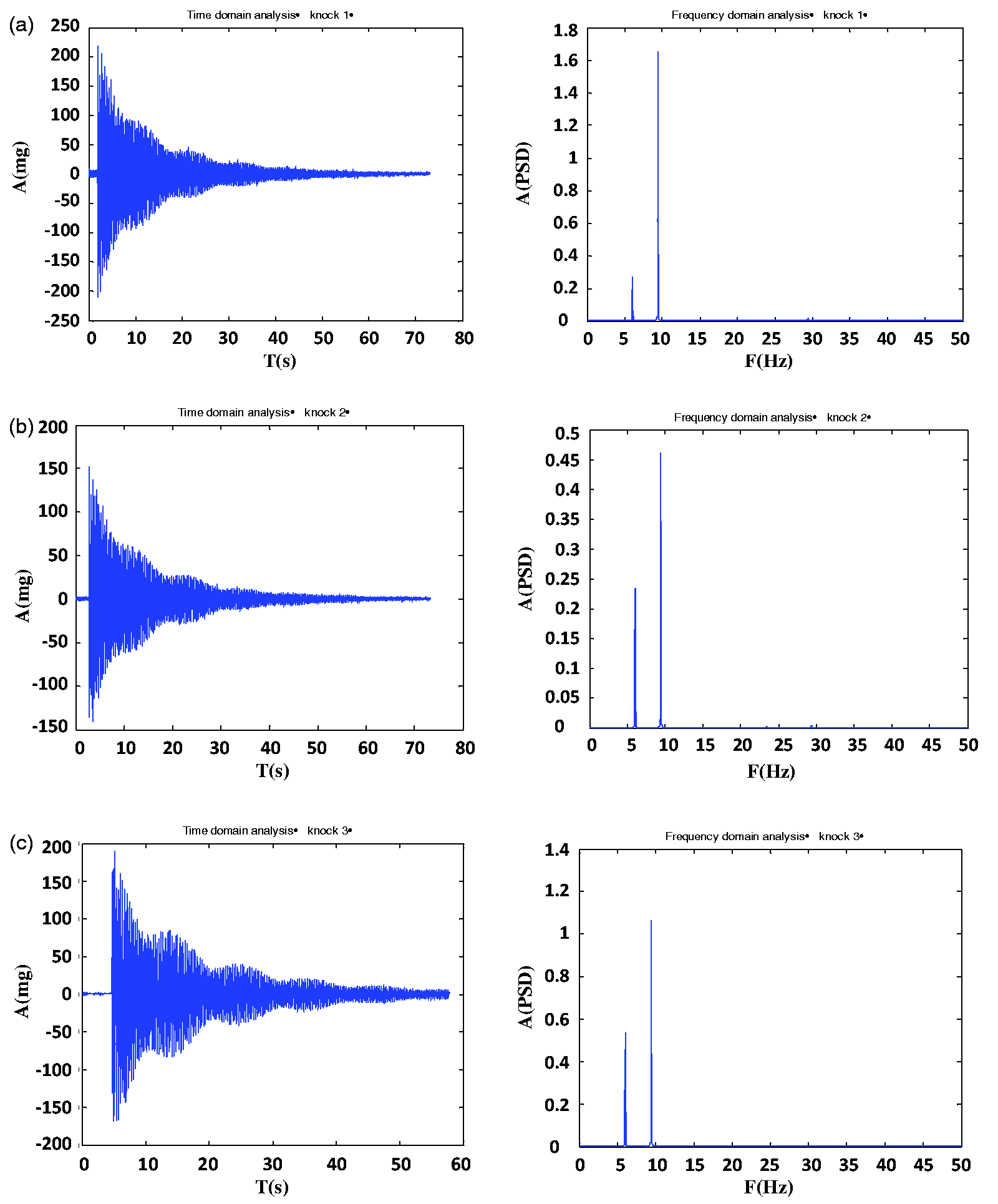
Time and frequency analysis of the knock test. (a) Knock 1 (b) Knock 2 (c) Knock 3.
Error analysis of frequency (knocks 1, 2, and 3).
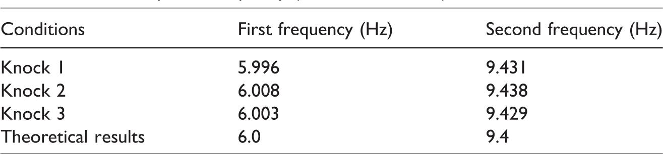
According to Figure 9 and Table 4, the first frequency of platform model is approximately 6 Hz, and the second frequency is approximately 9.43 Hz. The experimental results are in accordance with the corresponding numerical simulation results using ANSYS and show that the FWLVIS could reflect the vibration of platform model with considerable precision and accuracy.
Conclusions
In this study, the FWLVIS integrated with a wireless low-frequency acceleration sensor, and acquisition software was designed for fast inspection of the low-frequency characteristics of offshore platform structures. A swinging single pendulum was employed to simulate the low-frequency vibration of the offshore platform, and a knock test was performed on the offshore platform structure model to simulate the effect of sea ice. The reliability and excellent low-frequency performance of proposed FWLVIS are verified. The experimental results show that the designed FWLVIS with high reliability, no wiring, and low-frequency vibration inspection is suitable for vibration inspection of offshore platforms and has broad application prospects. In the future, more tests should be conducted before the proposed system can be used.
Footnotes
Declaration of conflicting interests
The author(s) declared no potential conflicts of interest with respect to the research, authorship, and/or publication of this article.
Funding
The author(s) disclosed receipt of the following financial support for the research, authorship, and/or publication of this article: This study was financially supported by grants from the National Natural Science Foundation of China (Project Nos. 51108060 and 51350110230) and the National Key Technology Research and Development Program during the Twelfth Five-Year Plan Period (Project No. 2011BAK02B01).