
Abstract
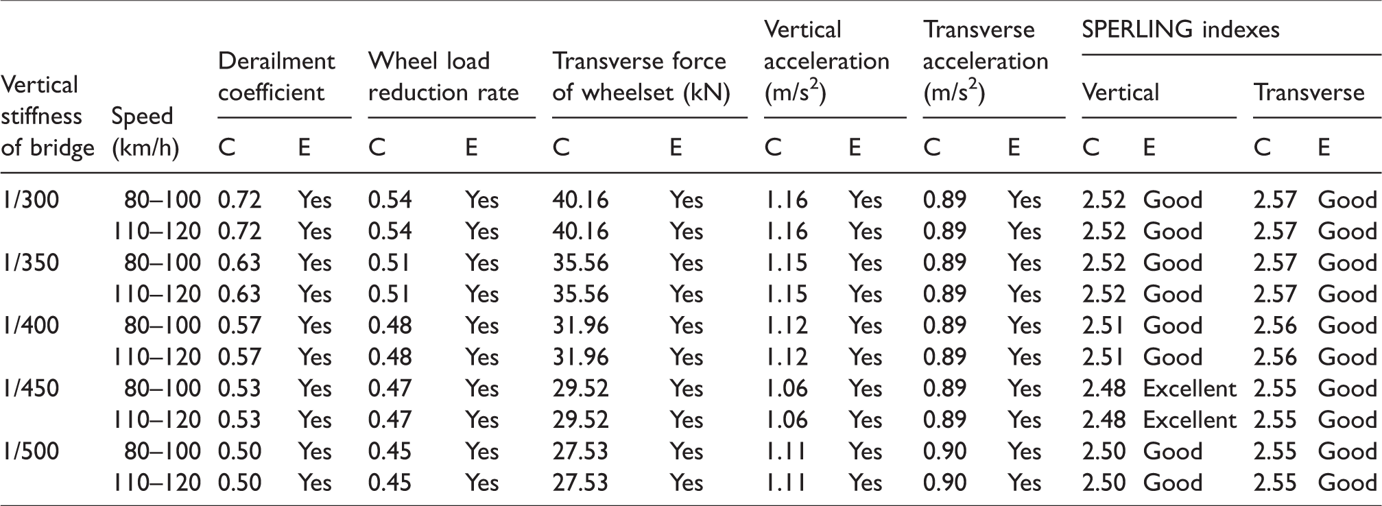
In order to analyze the influence of the stiffness change of the long-span track bridge on running safety of the train, a bridge and train analysis model, based on Chongqing Egongyan track bridge, is established to simulate and evaluate the spatial coupling dynamic response of the wind–train–bridge system through stiffness change and to propose the reasonable stiffness limit range of the long-span track suspension bridge. The results show that the dynamic characteristics of the bridge are good, and the safety of train operation and ride comfort meet the requirements when the vertical stiffness is 1/300–1/500 and the lateral stiffness is 1/600–1/1200; the dynamic response of the bridge and the running safety of the train are significantly sensitive to the stiffness change of the bridge, especially when the wind speed is 25 m/s and the vertical stiffness is 1/300, at this time, the derailment coefficient and the wheel load reduction rate reach 0.72 and 0.54, respectively, which are close to the limit standard, indicating that there are some potential safety hazards in train operation.
Introduction
Suspension bridge is a kind of bridge with cable bearing tension as its main bearing component, which is composed of main cable, stiffening girder, pylon, suspender, etc. As a flexible suspension system, suspension bridge is the most spanning bridge type so far, so it is widely favored by engineers. With the continuous development of urban public transport, the long-span track suspension bridges are more and more widely used in urban track transit due to their unique advantages.1,2
According to the Code for Design of Urban Rail Transit Bridges (GB/T 51234-2017), when a train travels to a track bridge, there will be lateral vibration besides vertical vibration. Both of them will have a greater impact on the safety of train operation and ride comfort. Therefore, the vertical and transverse stiffness of the bridge structure should meet certain value requirements.3–5 The main purposes are as follows:
To ensure the safety of train operation. To satisfy passengers’ comfort. To ensure the stability of the track and other equipment on the bridge. To ensure that the actual stress state of the bridge structure is within the design control range.
Thus, a large number of research scholars adopt the methods of model test, field test, and numerical analysis to analyze the influence of bridge stiffness change on track geometric alignment. And the relationship between the bridge stiffness and the train travel ability was further studied. For example, Gou et al.6,7 carried out the dynamic performance analysis of railway bridges and studied the influence of bridge transverse deformation on track geometric alignment of high-speed railway. Takai 8 studied the influence of track irregularity on the safety and comfort of train operation. Esveld 9 analyzed the transfer function of track irregularity excitation on vehicle body vibration acceleration. Yau 10 studied the influence of structural deformation on the running performance of the maglev train. For the long-span track suspension bridge as the throat of urban rail, the stiffness directly affects the safety and economy of the track line. Therefore, in order to provide effective technical guarantee for determining the reasonable stiffness limit, this paper carries out the space-coupled dynamic response simulation of the wind–vehicle–bridge system to analyze the influence of the stiffness change of the long-span track suspension bridge on the running safety of the train.
Introduction of engineering
The dedicated Egongyan track bridge under construction is located in the upper reaches of the existing Egongyan Yangtze River Bridge about 45 m (edge). The Egongyan track bridge’s full length is 1650.5 m, whose pile number is from YDK39 + 589.429 to YDK41 + 239.929. The bridge type scheme of Egongyan track Bridge is to arrange the holes with the Egongyan Yangtze River Bridge. The main bridge adopts the 600 m Main Span Self-Anchored Suspension Bridge scheme. The span combination of the main bridge is 50 + 210 + 600 + 210 + 50 = 1120 m, with a total of five spans. The structure layout of the bridge is shown in Figure 1. According to the overall layout requirements, the main bridge deck width allocation: 2.25 (cable area, air nozzle) +0.25 (rail) +2.35 (sidewalk) +0.9 (anti-collision, isolation belt) +10.5 (track boundary) +0.9 (anti-collision, isolation belt) +2.35 (sidewalk) +0.25 (rail) +2.25 (cable area, air nozzle) = 22.0 m, the cross-section layout is shown in Figure 2. The top elevation of the West Tower is 327.9 m and the bottom is 170.0 m. The top elevation of the East Tower is 327.9 m and the bottom is 164.0 m. Sections of all towers are rectangular hollow thin-walled, which is shown in Figure 3. The main cable is composed of three spans, of which the theoretical span of side span is 210 m, the theoretical span of main span is 600 m and the theoretical vertical span ratio of main span is 1:10, which is shown in Figure 4. There are 122 suspension points in the whole bridge, where a single suspension cable is installed at the same suspension point, totaling 122 suspensions.
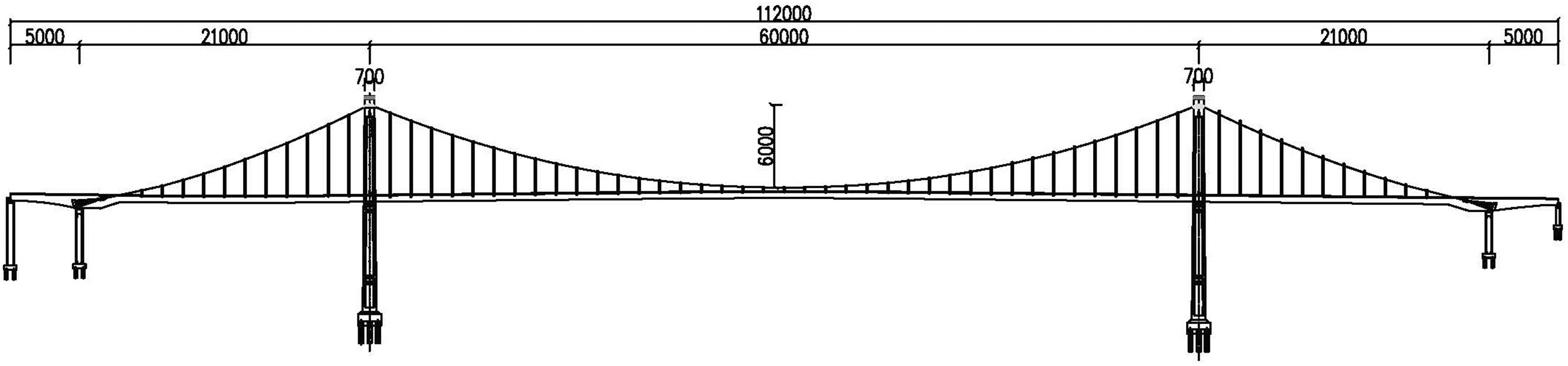
Bridge structural layout (unit: cm).
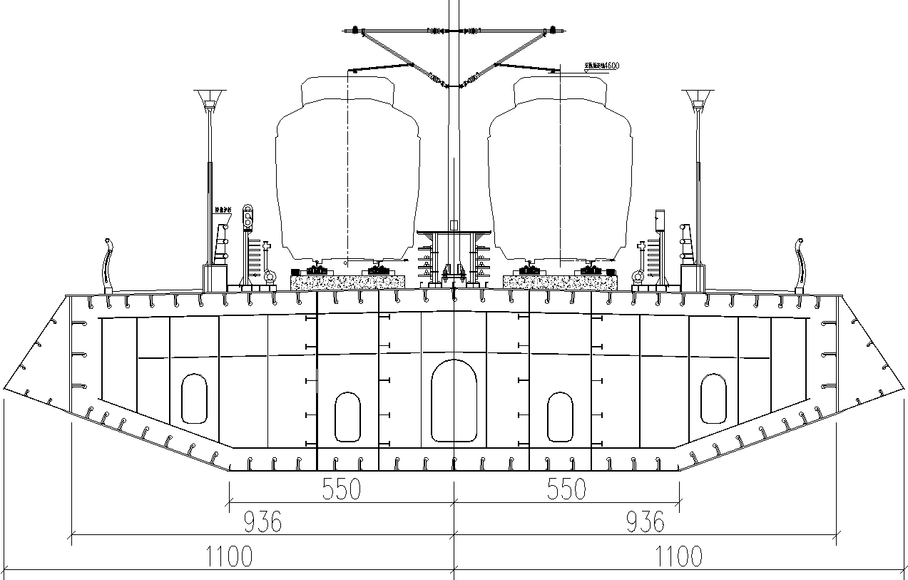
Cross-sectional layout (unit: cm).
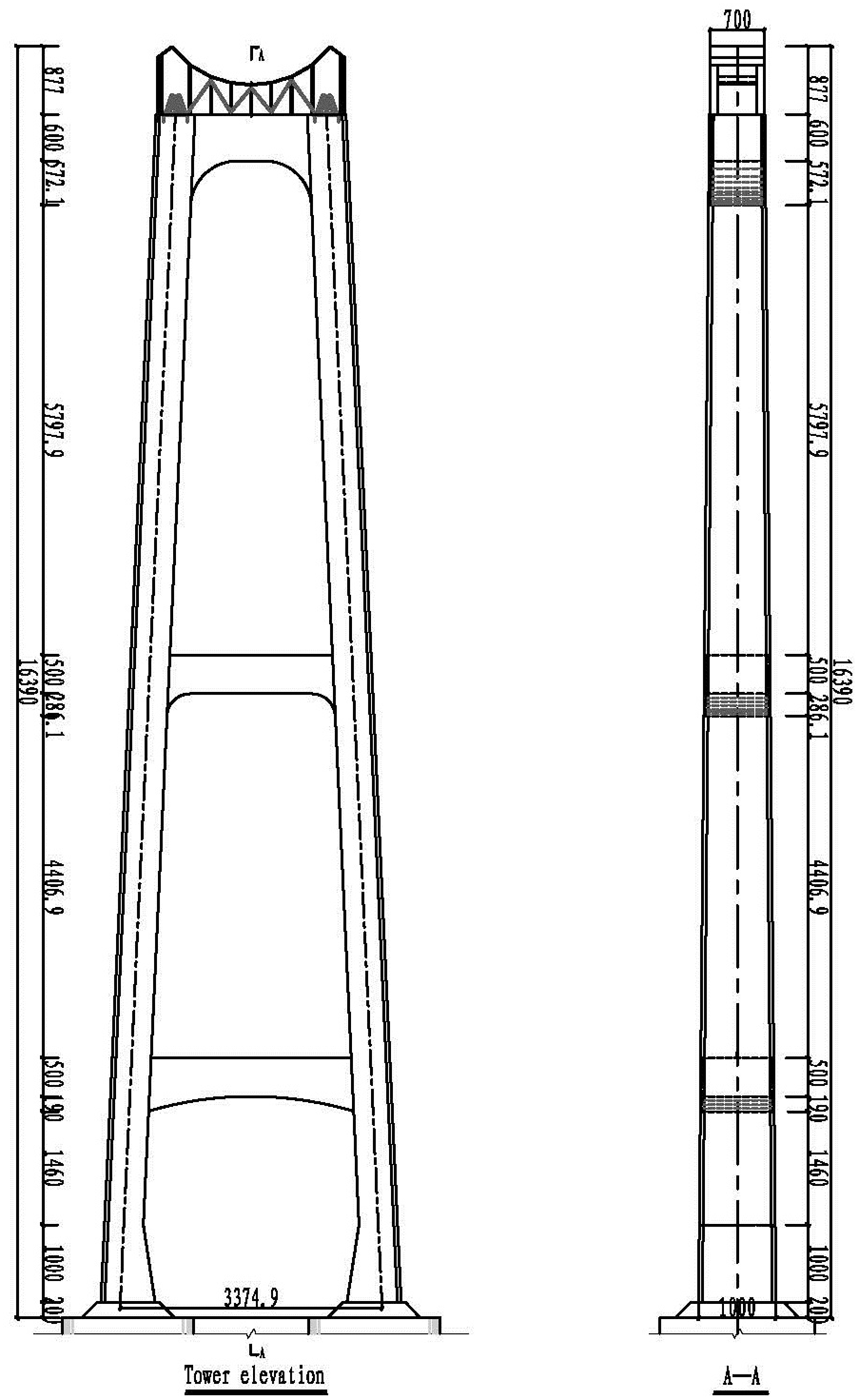
Layout of bridge tower (unit: cm).

Cross-sectional layout of cable.
Stiffness limit and change simulation
Although there is no stiffness regulation for the long-span track suspension bridges in the existing bridge design codes at home and abroad, the existing long-span track suspension bridges can provide reference for analyzing bridge stiffness.
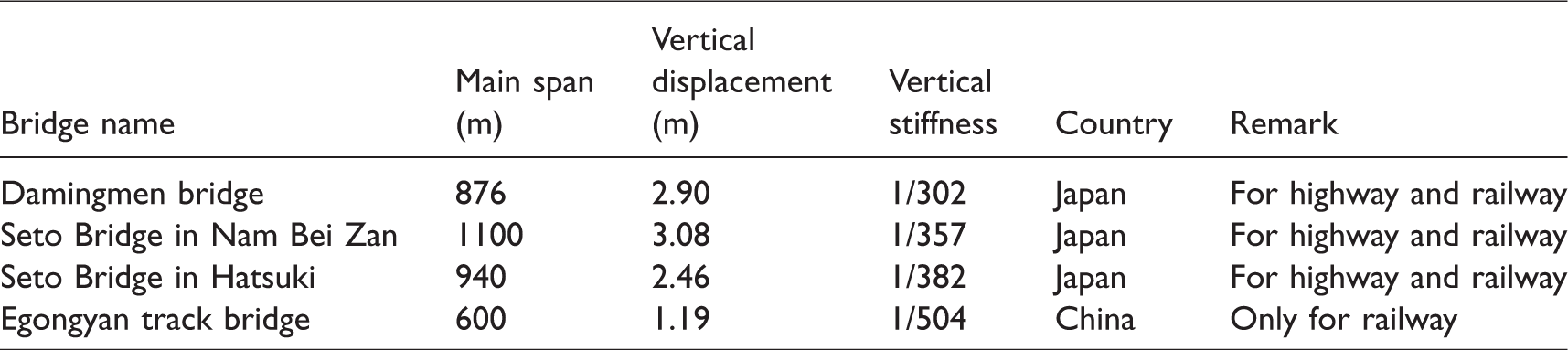
It can be seen from Table 1 that the vertical rigidity limit of the long-span track suspension bridges can be taken as 1/300–1/500. According to the design criteria of Japanese railway structures, the bridge structure generally has greater horizontal stiffness and the horizontal direction deformation is smaller when the train is running, so it is generally not stipulated in the design. In terms of special instances, the upper limit of deflection of horizontal beam is generally not more than 1/2 of the design limit value in vertical direction. 11 Considering the safety reserve and economic factors, the lower limit can be multiplied by the safety factor of 1.2. Therefore, the transverse stiffness limit of the long-span track suspension bridge can be 1/600–1/1200.
Vertical stiffness control parameters of typical suspension bridges.
The dedicated Egongyan track bridge in Chongqing is taken as the prototype to analyze this problem. The vertical stiffness of the bridge, taking into account the loads of trains and crowds, varies from 1/300 to 1/500 by modifying the elastic modulus of the structure. The stiffness of the bridge is simulated by taking 1/300, 1/325, 1/350, 1/375, 1/400, 1/425, 1/450, 1/475, and 1/500, respectively.12,13
Analysis model
Bridge and vehicle model
In this paper, Technische Datenverarbeitung (TDV) RM Bridge is used to carry out finite element simulation analysis. The bridge tower and main girder are simulated by the beam element, the main cable is simulated by the segment catenary element. The suspension cable is simulated by the cable element. Furthermore, the boundary conditions are treated according to the actual situation. The bottom of tower and pier are consolidated while the main girder is unconstrained along the bridge direction. The vertical and transverse directions of the bridge are restrained at pier and pylon, and the main cable is consolidated at anchorage point of the main girder. Based on these, the refined model is established, as shown in Figure 5.
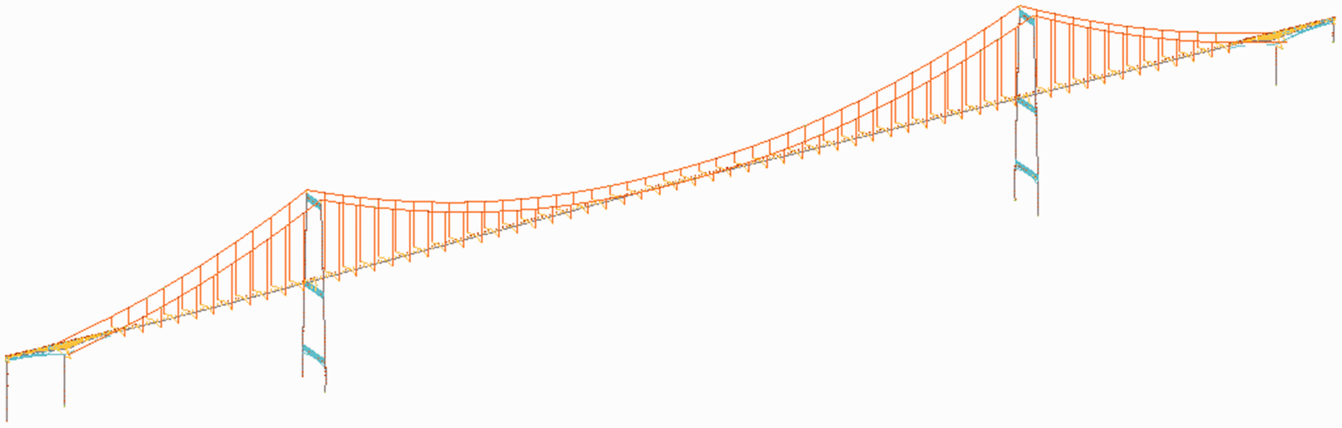
Finite element model of bridge.
The train adopts a two-series four-axle vehicle, and its spatial vibration includes five degrees of freedom, including shaking head, side swing, nodding, roll and sinking and floating. Each wheelset includes two degrees of freedom, including side swing and shaking head. So there are 23 degrees of freedom for the whole train. Based on the dynamics of the multi-body system, the train is regarded as a moving multi-rigid-body system, and the spatial vibration model is established, as shown in Figure 6. The following assumptions are used for the vehicle vibration analysis of the long-span track suspension bridges:
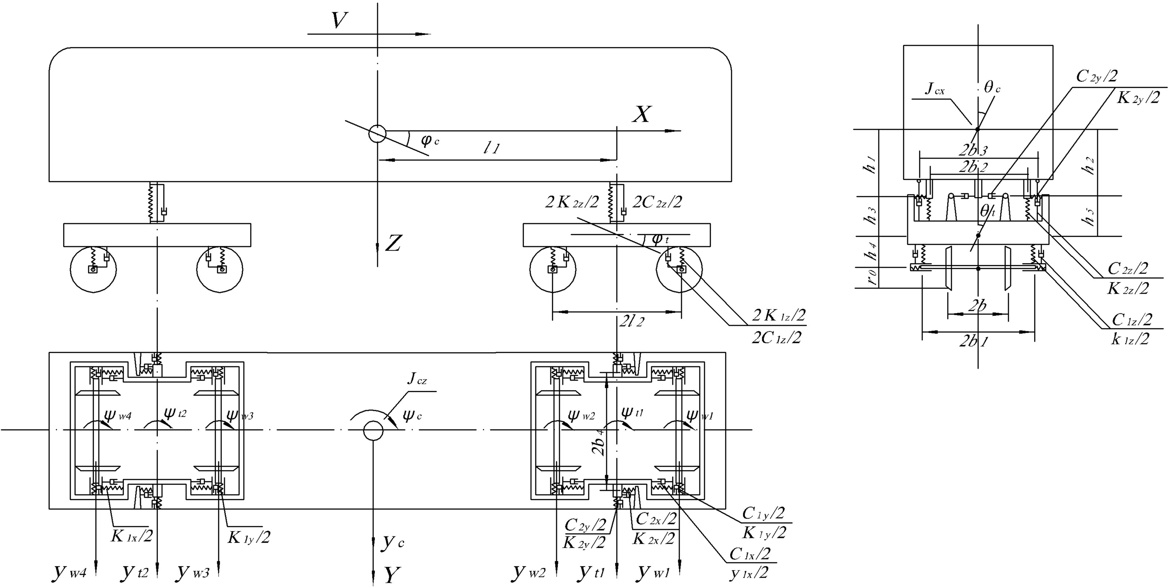
Spatial vibration analysis model of train.
The body, bogie, and wheelset are rigid bodies.
The influence of vehicle, vehicle longitudinal vibration and vehicle on bridge vibration and driving speed is not considered.
The wheelset, bogie, and car body are all subjected to the micro-vibration.
The spring is linear. The damping is calculated by viscous damping, and the creep force is calculated by linear.
Along the vertical direction, the vertical displacement of the wheelset and the rail is the same.
The nodding motion, wheel-to-wheel roll, and shaking motion of the frame are ignored.
According to the principle of stationary value of dynamic potential energy and the “set-in-right position” rule of matrix formation,
14
the equation of bridge motion is established, as shown in equation (1). Based on the D’Alembert principle, the equation of train motion
15
is obtained in equation (2)


The interaction model of the bridge and the train is established by equations (1) and (2), and the motion equations of the bridge and the train are solved independently. By separating iteration, the coordinated conditions of displacement of the bridge and the train at the wheel–rail contact are the same, and the loads are equal in magnitude and opposite in direction. 16
Track irregularity simulation
According to the six-level line spectrum of the United States, the following models are established:
Vertical irregularity:
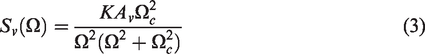
Direction irregularity:
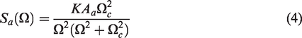
Horizontal and gauge irregularities:
Analysis of the relation between bridge stiffness change and train running safety
Assessment standard
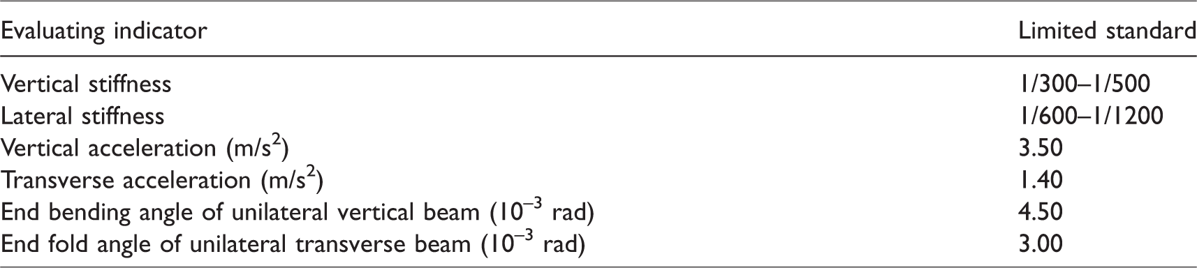
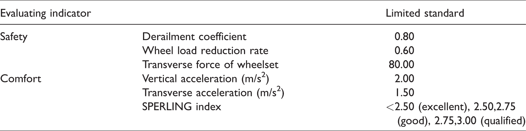
According to the regulations of train running and bridge safety assessment in domestic and foreign standards, such as code for design of urban rail transit bridge (GB/T 51234-2017), code for rating existing railway bridges (2004120), railway vehicles-specification for the evaluation of the dynamic performance and accreditation test (GB 5599-85), and the design criteria of Japanese railway structures, the dynamic response evaluation criteria17–20 of bridges and trains are determined by the wind–vehicle–bridge coupling vibration analysis of railway bridges, as shown in Tables 2 and 3.
Bridge evaluation criteria.
Evaluation criteria for trains.
Static characteristics analysis
According to the finite element analysis, for the Egongyan track bridge under the action of the train vertical static live load and crowd load, the vertical stiffness of the main girder is 0.99 m + 0.20 m = 1.19 m<L/500 = 1.20 m. The bending angle tan(0.04) = 0.7‰<4.5‰, so the vertical stiffness meets the requirements. Under the action of the transverse swaying force, centrifugal force, wind force, and temperature force of the train, the lateral stiffness of the main girder is 0.23 m<L/1200 = 0.50 m. Under the combination of additional forces, the bending angle tan(0.033) = 0.6‰< 3.0‰, so the transverse stiffness meets the requirements.
Dynamic response analysis and evaluation
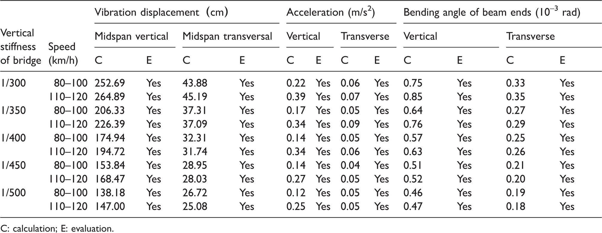
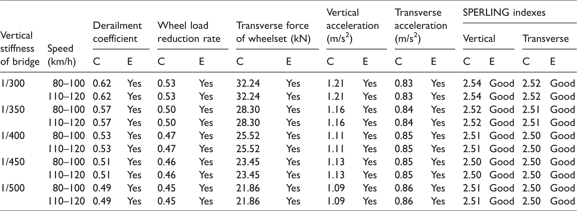
The train is composed of six sections (trailer + motor vehicle + motor vehicle + motor vehicle + motor vehicle +trailer). When the simulation calculation and analysis of wind–vehicle–bridge coupling dynamic response are carried out,21,22 the speed is 120 km/h and the average wind speed on the bridge deck is not more than 25 m/s. The results are as shown in Tables 4 to 6.
Maximum value of bridge dynamic response calculation and evaluation.
C: calculation; E: evaluation.
Maximum value of dynamic response calculation and evaluation of train (EMU).
Maximum value of train (trailer) dynamic response calculation and evaluation.
Vibration displacement evaluation is carried out after the stiffness limit criterion is converted and the crowd load is deducted.
According to the analysis and evaluation results of wind–vehicle–bridge coupling vibration, the dynamic response evaluation indexes of bridges are within the limits, and the dynamic characteristics are good. The safety of train operation and ride comfort meet the requirements, and the bridges and trains are in normal operation.
Relationship between bridge stiffness change and train running safety
Based on the results of simulation calculation and analysis of spatial coupling dynamic response of the wind–vehicle–bridge system, when the average wind speed of the bridge deck is 25 m/s, the vertical stiffness of bridge varies from 1/300 to 1/500, and the train passes the bridge at a speed of 80–120 km/h, the relationship between derailment coefficient, wheel load reduction rate, wheel pair lateral force, vertical acceleration, lateral acceleration, SPERLING comfort index, and the vertical stiffness of the bridge is shown in Figures 7 to 12.
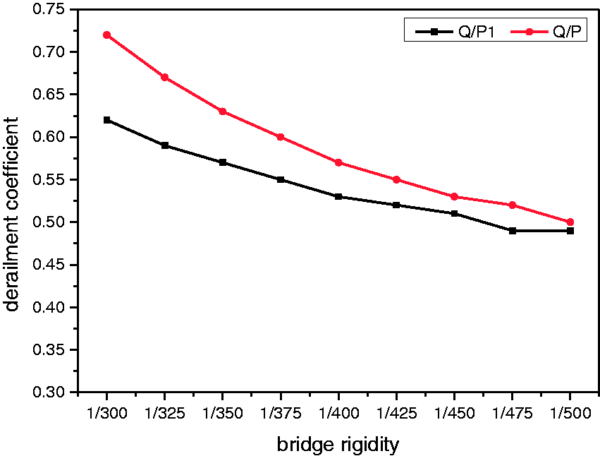
Derailment coefficient against bridge rigidity curve (Q/P1 for motor vehicle and Q/P for trailer).
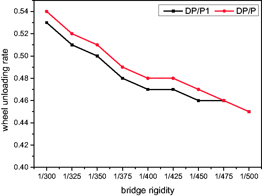
Load reduction rate against bridge rigidity curve (DP/P1 for motor vehicle and DP/P for trailer).
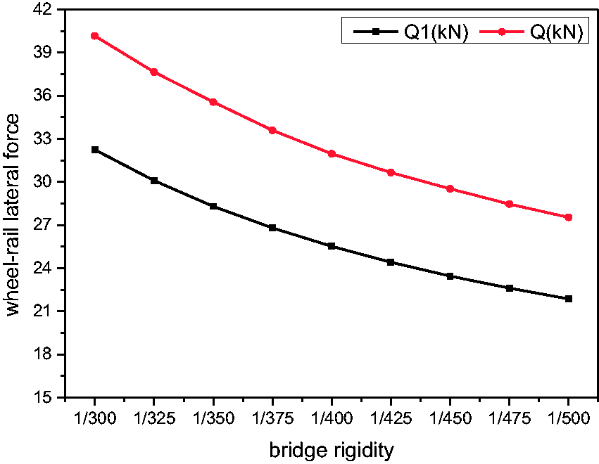
Lateral force of the wheelset against bridge rigidity curve (Q1 for motor vehicle, Q for trailer).
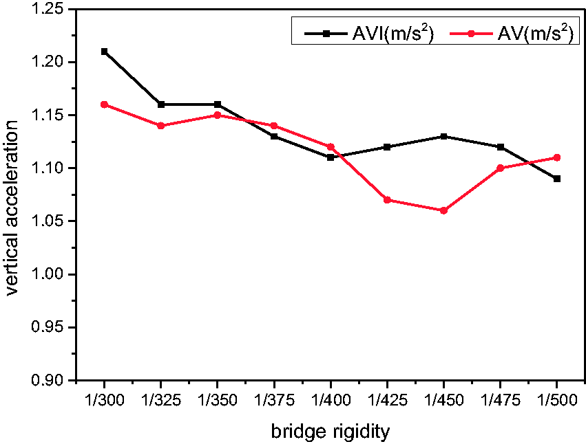
Vertical acceleration against bridge rigidity curve (AV1 for motor vehicle, AV for trailer).
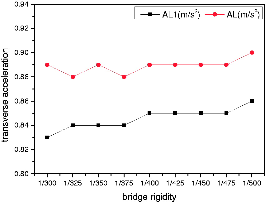
Lateral acceleration against bridge rigidity curve (AL1 for motor vehicle and AL for trailer).
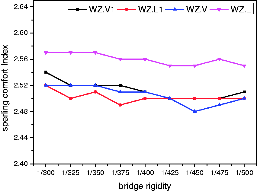
SPERLING comfort index against bridge rigidity curve (WZ.V1 for vertical, WZ.L1 for transverse, WZ.V for vertical, WZ.L for transverse).
The relationship between bridge stiffness change and train running performance has been analyzed. The results show that when the vertical stiffness of the long-span track suspension bridge changes from 1/300 to 1/500, the derailment coefficient, wheel load reduction rate, and wheel-to-wheel lateral force all show a decreasing trend with the increase of vertical stiffness. The vertical acceleration is more sensitive to vertical stiffness, while the transverse acceleration is not significant. SPERLING indexes all meet the good standard.
Conclusion
This paper carries out the wind–train–bridge coupling vibration analysis by the stiffness change simulation and the following conclusions can be drawn:
The rationality of 1/300–1/500 vertical stiffness of the long-span track suspension bridge is verified, and the transverse stiffness limit can be determined on this basis. At the same time, the appropriate structural type and stiffness of the background engineering design are illustrated, which has important reference significance for similar engineering design. With the increase of the stiffness of the long-span track suspension bridge, the dynamic response indexes of bridge, such as vibration displacement, acceleration, and bending angle at the end of beam, tend to decrease, especially the vertical vibration displacement. The stiffness of the long-span track suspension bridge directly affects the safety of train operation. With the increase of vertical stiffness, derailment coefficient, wheel load reduction rate, and lateral force of wheel set decrease. When the wind speed is 25 m/s and the vertical stiffness is 1/300, the derailment coefficient can reach 0.72 and the wheel load reduction rate can reach 0.54, which are close to the limit standard, indicating that there are some potential safety hazards in train operation. In the ride comfort index, because the SPERLING index presents a good situation, it can be known that the vertical acceleration of the train is more sensitive to the stiffness of the bridge, while the lateral acceleration is not significant.
Footnotes
Declaration of conflicting interests
The author(s) declared no potential conflicts of interest with respect to the research, authorship, and/or publication of this article.
Funding
The author(s) disclosed receipt of the following financial support for the research, authorship, and/or publication of this article: This work was supported by major research and development projects on topics of artificial intelligence technology innovation in Chongqing (cstc2017rgzn-zdyfX0029), special social and livelihood key research and development projects on technology innovation and application demonstration in Chongqing (cstc2018jscx-mszdX0084).