
Abstract
A semi-active suspension variable damping control strategy for heavy vehicles is proposed in this work. First, a nine-degree-of-freedom model of a semi-active suspension of heavy vehicles and a stochastic road input mathematical model are established. Second, using a 1/6 vehicle as an example, a semi-active suspension system with damping that can be adjusted actively is designed using proportional relief and throttle valves. The damping dynamic characteristics of the semi-active suspension system and the time to establish the damping force are studied through a simulation. Finally, a variable damping control strategy based on an actuator motion state is proposed to adjust the damping force of the semi-active suspension system actively and therefore satisfy the vibration reduction requirements of different roads. Results show that the variable damping control suspension can substantially improve vehicle ride comfort and handling stability in comparison with a passive suspension.
Introduction
Suspension system is the general term for all force transfer devices between the frame and the axle of a vehicle. This system transfers force and torque between the wheel and the frame and buffers impact loads transmitted from an uneven road surface to the frame or body, thereby attenuating the vertical vibration of the body and ensuring ride comfort, driving harshness and handling stability.
Three types of suspension, namely, passive, semi-active and active, are commonly used for heavy vehicles. The stiffness and damping of the passive suspension cannot be adjusted automatically with the change in driving speed and road conditions and cannot achieve the desired performance under various working conditions.1–3 Although the active suspension has strong adaptability and evident improvement of ride comfort and stability, it requires external energy supply which is more complex and costly than the semi-active suspension.4,5 A semi-active suspension is extensively used in heavy vehicles given its low cost, simple manufacturing process and favourable damping effect.6,7
The stiffness of a spring is difficult to adjust. Thus, most semi-active suspensions are realised by changing the damping; thus, a variable-damping damper is the most important actuator in a semi-active suspension system.8,9 Variable damping dampers are classified into magnetorheological, electrorheological and solenoid valve. Among these damper types, the electromagnetic valve-type variable damping shock absorber has the most compact structure, quick response and reliable performance.
Guy, 10 Ivers and Miller 11 and Rajamani and Hedrick 12 confirmed experimentally that a continuously controlled damping suspension can improve the ride comfort and road adhesion performance of a vehicle better than a traditional suspension. Besinger et al.13,14 conducted a hardware-in-the-loop test of vehicles equipped with continuously adjustable dampers. The test verified that the vibration acceleration of a vehicle body and the dynamic load of a tire are reduced by 28% and 21%, respectively. Many scholars have conducted performance analyses and experimental studies of an adjustable damping shock absorber.15–17 A suspension with controllable damping is used in extant research for light vehicles, but research on the suspension with adjustable damping for heavy vehicles is rare.
Many control methods have been used for a semi-active suspension of heavy vehicles. Sulaiman et al. 18 and Valášek et al. 19 studied the semi-active suspension groundhook control of heavy vehicles. Their findings showed that a groundhook control can effectively reduce the dynamic load of tires and improve driving comfort. Yarmohamadi and Berbyuk 20 tested the control strategies of the semi-active suspension of a heavy vehicle; these strategies include groundhook, skyhook and groundhook–skyhook control strategies; the effect of a semi-active damper on vehicle dynamic performance was quantitatively displayed. Nicolas et al. 21 expounded the application of a fuzzy logic method in a vehicle’s semi-active suspension and analysed its advantages over conventional control method. Salah 22 designed a neuro-fuzzy controller to improve the damping and ride comfort of a semi-active vehicle suspension system. The simulation results showed that the proposed controller has reduced suspension travel and has improved ride quality. Nguyenf et al., 23 Zheng et al. 24 and Song et al. 25 studied the fuzzy sliding mode controller of a semi-active suspension to provide improved vibration control capability with low power consumption. The whole vehicle control effect is disregarded despite adopting various control methods in the semi-active suspension system of heavy vehicles.
First, a nine-degree-of-freedom (9-DOF) model of the semi-active suspension system of heavy vehicles is established in the present work. Second, a variable damping semi-active suspension is designed for heavy vehicles. The damping dynamic characteristics of the semi-active suspension system and the time to establish damping force are investigated through a simulation. Variable damping control (VDC) strategy is used to control a heavy vehicle, and the control effect is analysed. Results show that, in comparison with the passive suspension, the VDC suspension can considerably reduce the vibration of body acceleration, pitch angle acceleration, roll angle acceleration, suspension deflection and tire deflection. Moreover, the VDC suspension has an improved control effect on vehicle ride comfort and handling stability.
Semi-active suspension system dynamics
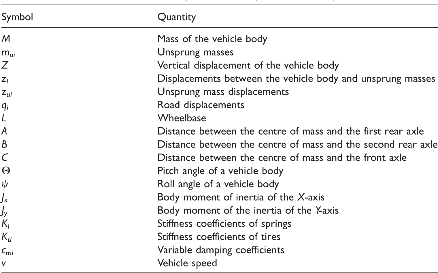
The 9-DOF semi-active suspension system model of a heavy vehicle is illustrated in Figure 1. This model consists of six vertical unsprung masses and DOFs due to pitch, roll and vertical motion of the mass centre. The variables of the semi-active suspension model are listed in Table 1.
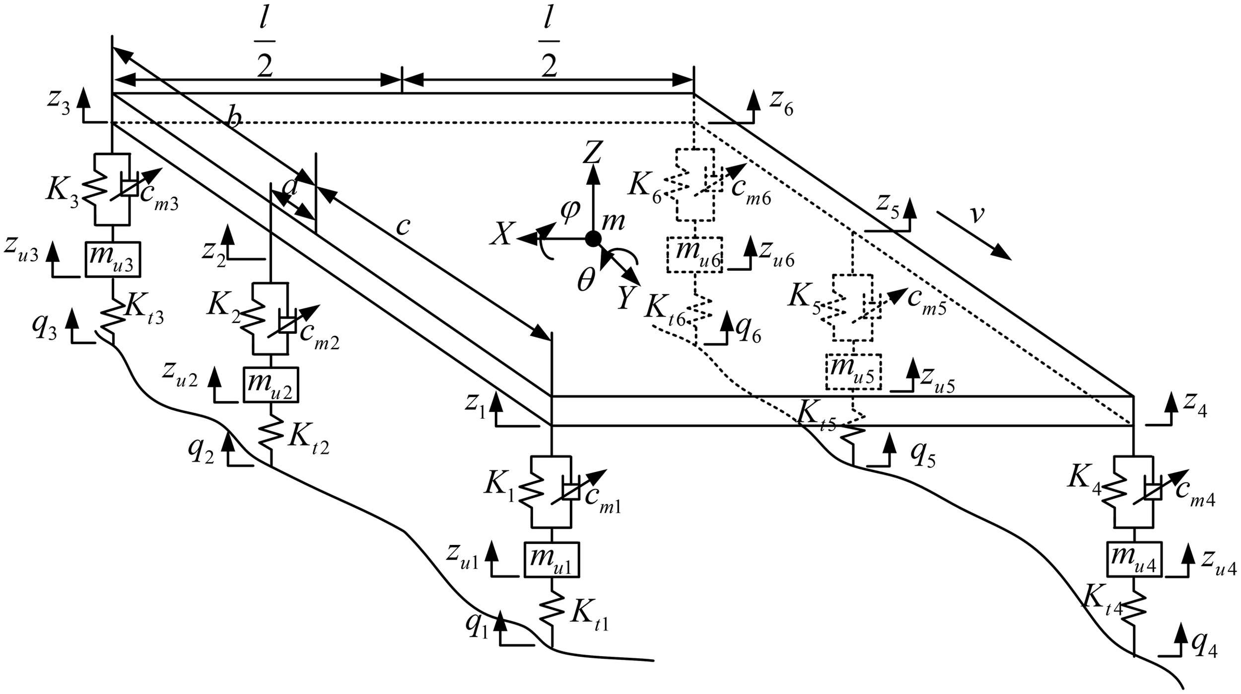
9-DOF model of a semi-active suspension system.
Variables of the semi-active suspension model (i = 1, 2, 3, 4, 5, 6).
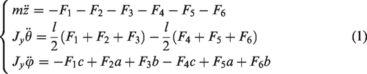
According to Newton’s second law, we can obtain the vertical motion of the body centroid, body pitching and roll rotation equations as follows
The dynamic equation of the vertical motion of the unsprung mass is

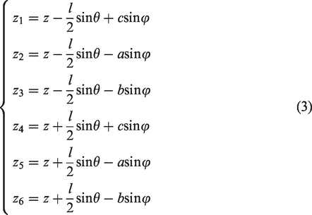
According to the spatial motion law of a rigid body, the dynamic relationship among the four suspension systems, the body connection points, body centroid vertical movement, pitching rotation and roll rotation can be demonstrated as
As a rigid body structure, the pitch and roll angles of the vertical body assume a change in a small angle range. Furthermore, the following equations are set

The state equation is established, and the system state variable X is defined as

The semi-active suspension system can be expressed in the following state equation

System output Y is defined as

The output equation of the system is

Random road output model
Road roughness is the most important factor that affects vehicle ride comfort which is typically used to describe the roughness degree of pavements. This factor makes the vehicle produce driving resistance and vibration and affects the ride comfort, handling stability, fatigue life of components and other aspects.
26
The statistical characteristics of pavement roughness are frequently expressed by power spectral density function Gq(n)
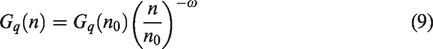
When 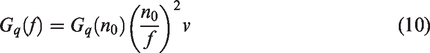
The velocity power spectral density function is

The time-domain mathematical model of road excitation on a single wheel is described as follows

Structure and characteristics
Structure and working principle of the semi-active suspension system
Using the right front suspension as an example, a diagram of the variable damping semi-active suspension structure for heavy vehicles is depicted in Figure 2.
1/6 Vehicle structure diagram of an adjustable damped semi-active suspension.
A vehicle is motivated by the road surface whilst running, and a relative motion between the wheel and the vehicle body occurs. With the piston moving downwards, the suspension is in a compression stroke. The oil in the cylinder can be pressed into the accumulator through the proportional relief and throttle valves. These valves work under different piston speeds. The system pressure becomes low alongside the piston speed. Thus, the proportional relief valve is closed, and the oil enters the accumulator only through the throttle valve. When the piston accelerates, the system pressure increases until the proportional relief valve can open. Therefore, the oil enters the accumulator through both valves. The suspension is in the stretching stroke whilst the piston moves upwards. The oil in the accumulator can be sucked into the cylinder through the proportional relief and throttle valves. The working principle is the same as the compression stroke.
The opening pressure of the proportional relief valve is controlled by the voltage signal from the controller, and the voltage range is 0–10 V. The opening pressure of the proportional relief valve is directly proportional to voltage and can be regulated continuously by the voltage signal.
Mathematical model of the system
Hypotheses: (1) oil is incompressible; (2) the effect of temperature on oil characteristics is ignored; (3) the system has no oil leakage.
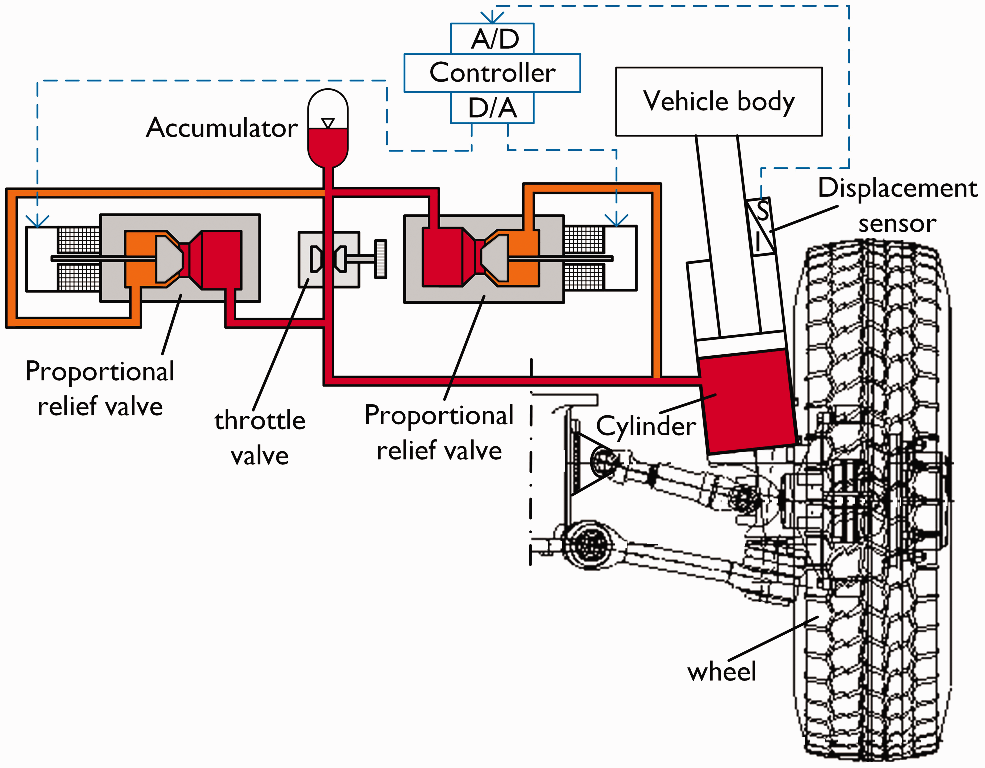
The flow formula for throttle valve is
The valve core of the proportional relief valve can adopt the mathematical model of a poppet valve. The opening pressure is proportional to the control voltage. The input voltage on the electromagnet can change from 0 to 10 V, and the force produced will change accordingly. Thus, the continuous change in the relief pressure can be obtained.
The flow formula for the proportional relief valve is as follows
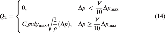
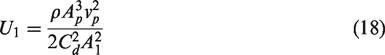
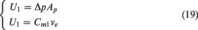
When the piston speed is low, the proportional relief valve remains closed. In addition, the oil only flows through the throttle valve. The flow rate that flows out of the hydraulic cylinder is equal to the flow rate at the throttle valve. The mathematical model of the system in this state is as follows
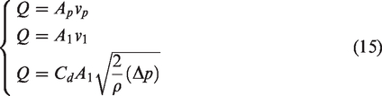
Thus
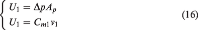
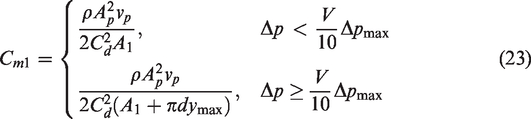
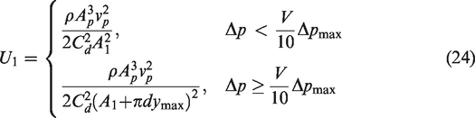
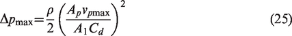
The pressure difference between the two ends of the proportional relief valve increases alongside the piston speed. The valve opens when the pressure difference reaches the opening pressure of the valve. The mathematical model of the oil that flows through the throttle and proportional relief valves is presented as follows
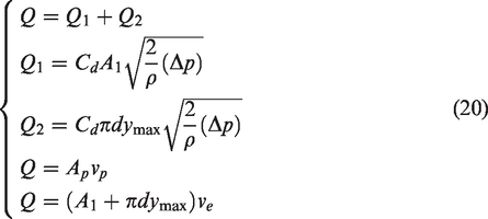
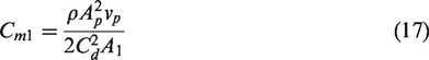
Thus
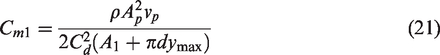
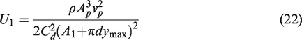
In summary, the expression of the equivalent damping coefficient is
The expression of the damping force is
Simulation of the system characteristics
The system is modelled and simulated using MATLAB/SIMULINK. The simulation and complete vehicle parameters are listed in Tables 2 and 3. The damping coefficient control characteristic, damping force control characteristic and damping force time curves are demonstrated in Figures 3 to 5.
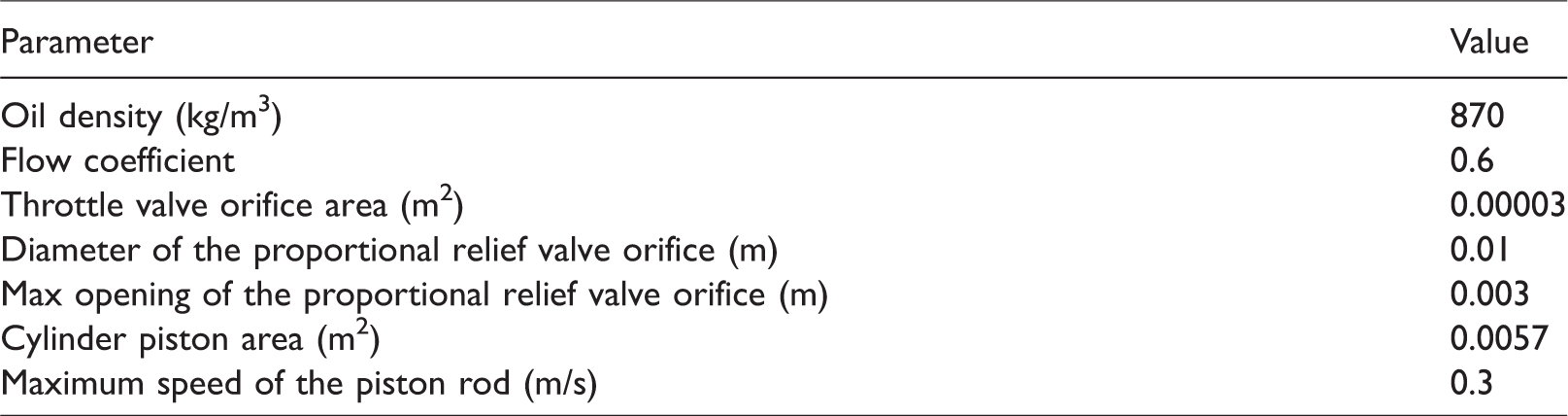
Simulation parameters.
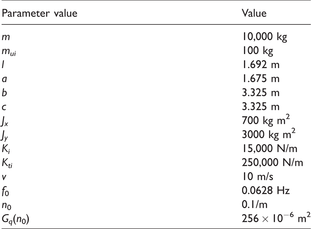
Main parameters of heavy vehicles (i = 1, 2, 3, 4, 5, 6).
The damping characteristic control curve is exhibited in Figure 3. The black curve is the damping coefficient control characteristic curve of the suspension system without adding voltage to the proportional relief valve. The curves from left to right are the control characteristics of the damping coefficient of the suspension system with the conditions that the proportional relief valve is added with 1–10 V. When the piston speed is low, the oil only flows through the throttle valve. In addition, the damping force is generated by the throttle valve because the slope of the curve enlarges accordingly. When the piston speed increases, the oil flows through the throttle and proportional relief valves. Thus, the damping force is generated by the two valves together, and the slope of the curve becomes small.
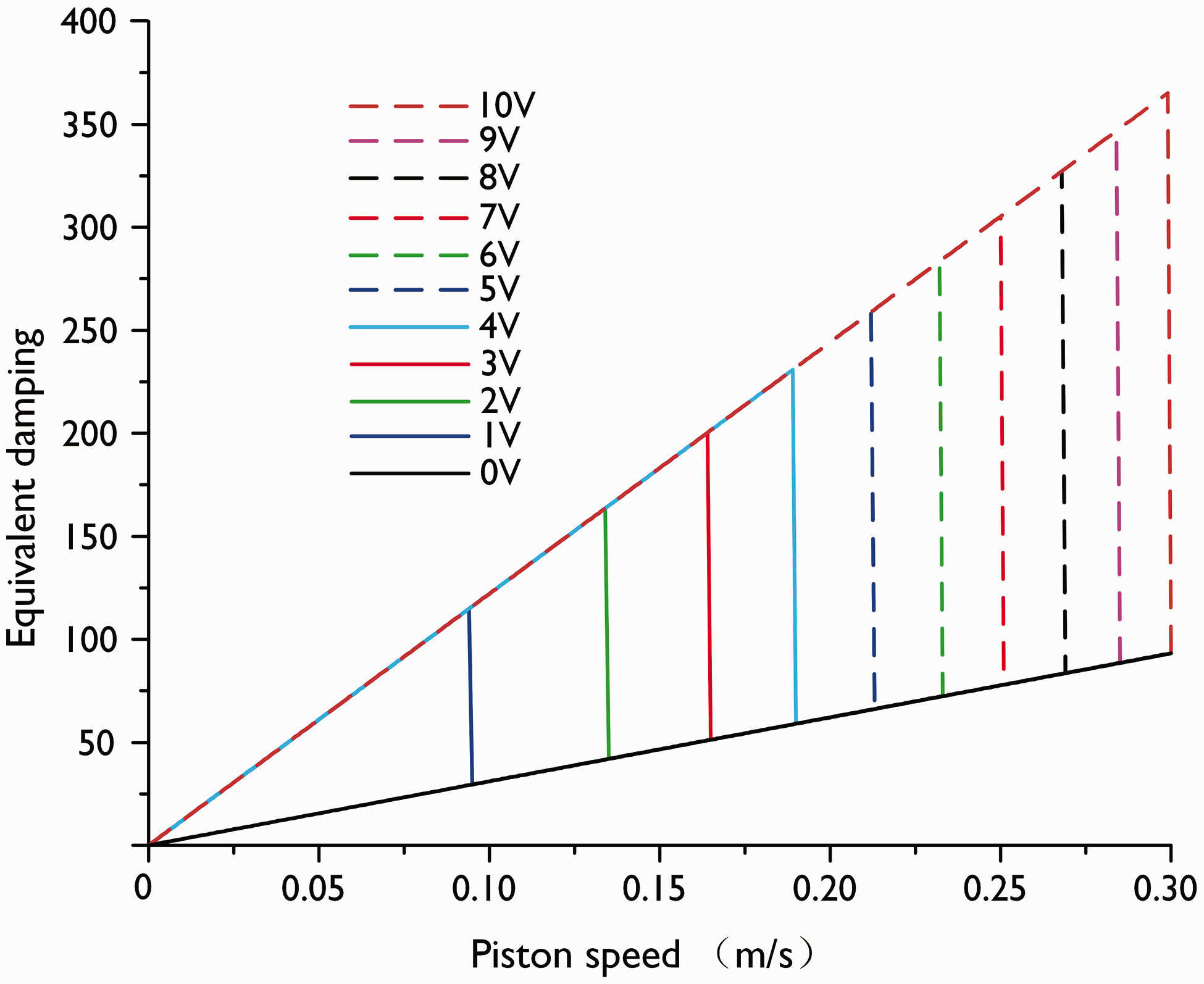
Damping coefficient control characteristic curve.
The damping force characteristic control curve is displayed in Figure 4. The black curve represents the damping force control characteristic curve of the suspension system without adding voltage to the proportional relief valve. The curves from left to right are the control characteristics of the damping force of the suspension system when the proportional relief valve is added with 1–10 V.
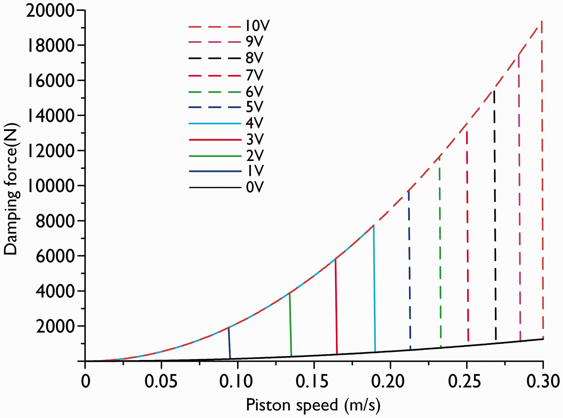
Damping force control characteristic curve.
The time curve for establishing damping force is presented in Figure 5. In the curve, the damping force increases from time 0 to a certain time and surges to the peak value of the damping force at this certain time. Therefore, this time quantum is required to establish the damping force completely under any voltage. In addition, a large control voltage indicates a long time required to establish the damping force.
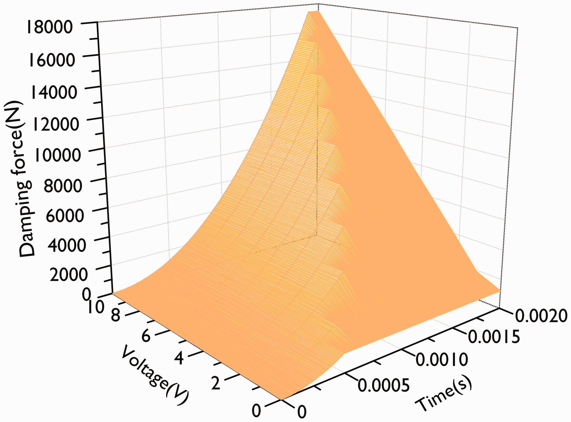
Damping force time curve.
In the simulation curve, we can control the damping characteristics of the semi-active suspension system by controlling the input voltage of the proportional relief valve.
The control signals of each suspension can be obtained by simulating the 9-DOF vehicle model. To present the verification results of the model, the control signal of the front axle is illustrated in Figure 6.
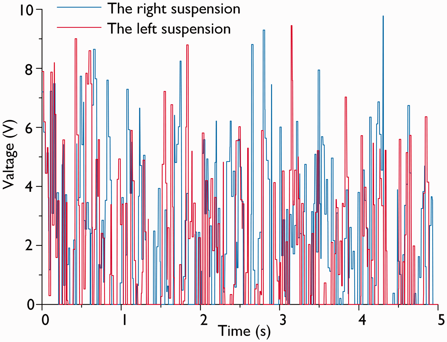
Control signal of the front axle.
Experiment and analysis of the VDC strategy
We propose a VDC strategy on the basis of an analysis of the damping characteristics of a semi-active suspension with variable damping in the fourth part. The displacement sensor is used to identify the motion state of the hydraulic cylinder. When the hydraulic cylinder is in the state of stretching, the control voltage is increased to improve the damping switching threshold of the system. Thus, the suspension is in a high damping state, and the vibration can be reduced quickly. When the hydraulic cylinder is in a compression state, the control voltage is reduced to not only decrease the damping switching threshold of the system but also maximise the elastic elements for moderating the impact. If the speed of the cylinder reaches the upper limit, then the control voltage must be reduced to increase the flow rate of the shock absorber. Thus, the damping force is constantly kept within a certain limit to avoid excessive impact and load. The VDC flowchart is demonstrated in Figure 7.
VDC flowchart.
Using the road of Class C as an example, the control strategy is used to control the whole vehicle. The heavy vehicle used in this work is depicted in Figure 8. The 1/6 variable damping semi-active suspension is exhibited in Figure 9. To verify the effect of the VDC suspension proposed in this work, the heavy vehicle was driven to the test site displayed in Figure 10. In contrast to the traditional passive suspension, the validity of the control strategy is verified.
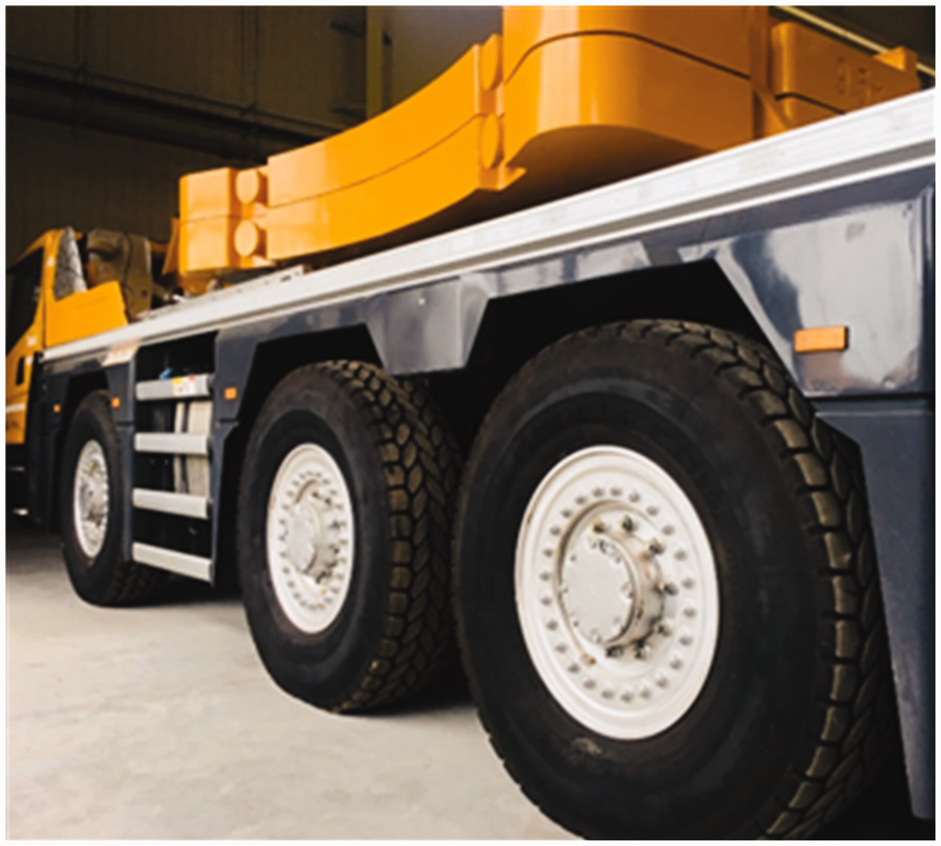
Heavy vehicle for the experiment.
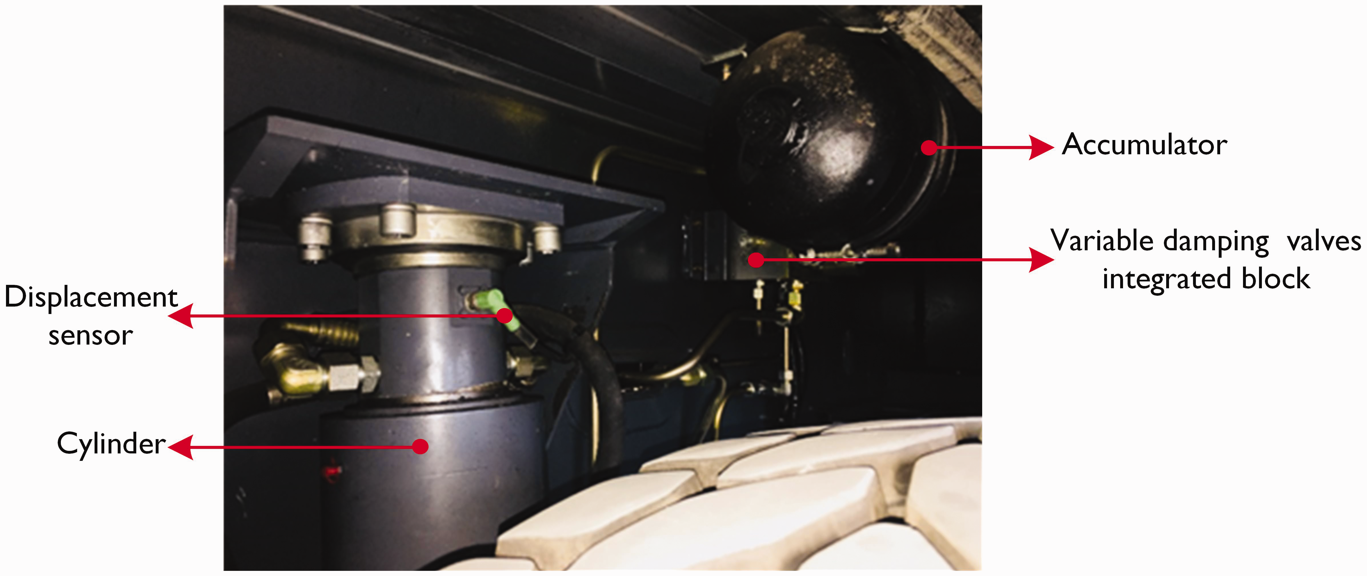
1/6 variable damping semi-active suspension.
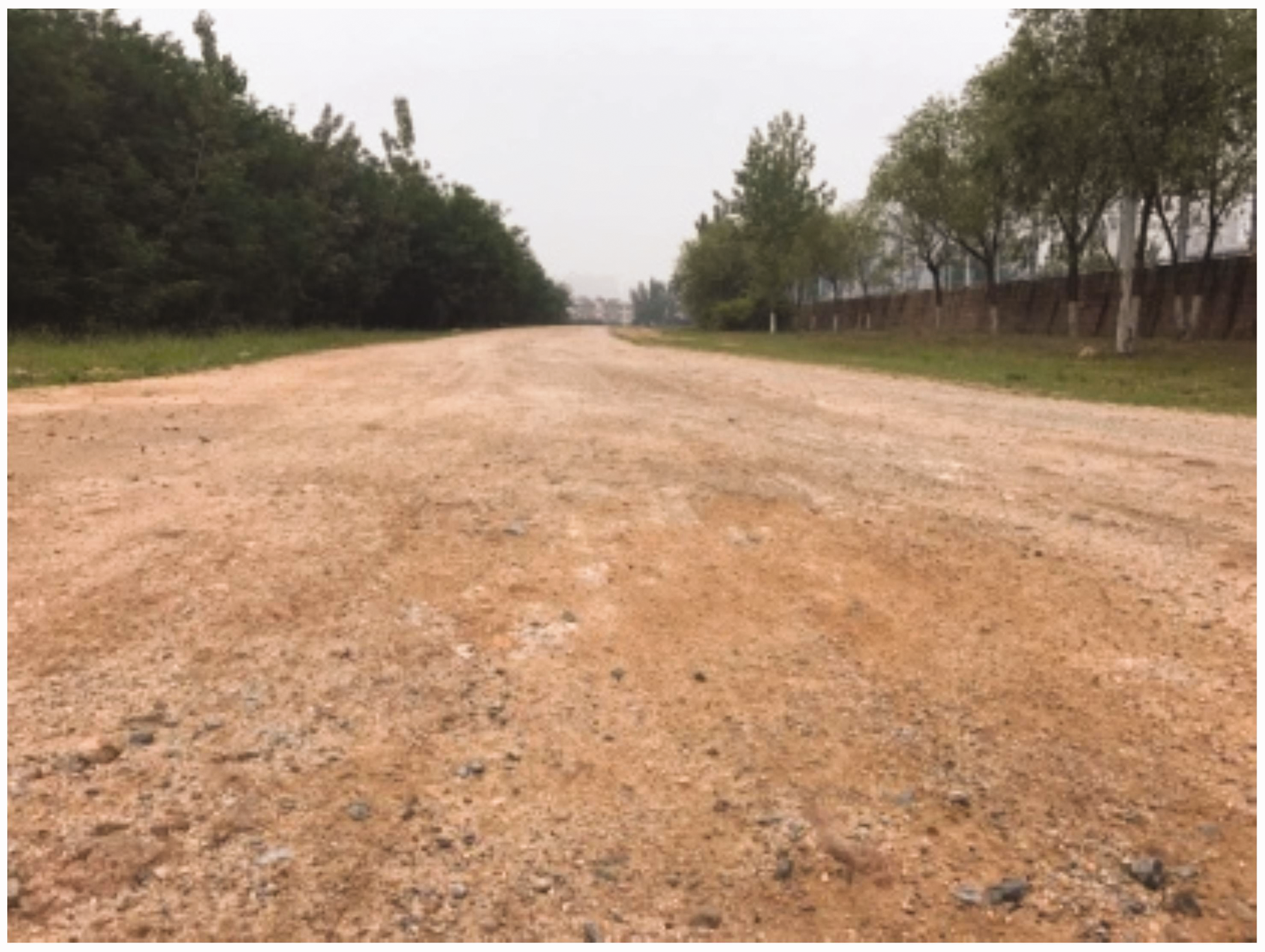
Test site.
The curves show that the semi-active suspension with VDC has better control effect than the traditional passive suspension on vehicle ride comfort and handling stability. In comparison with passive suspension, the VDC suspension can significantly reduce the vibration of body acceleration, pitch angle acceleration, roll angle acceleration, suspension deflection and tire deflection (Figures 11 to 17).
In Figure 11, the acceleration vibration of the vehicle body with a VDC suspension is considerably reduced in comparison with the vehicle body with a passive suspension system. Moreover, the results show that the peak acceleration of the vehicle body with the passive and VDC suspension systems are 2.91 and 1.38 m/s2, correspondingly. In Figures 12 and 13, the pitch and the roll accelerations of the vehicle body are better with the VDC suspension than with the passive suspension. In Figure 11, the peak pitch accelerations of the vehicle body with the passive and VDC suspension systems are 5.22 and 2.49 rad/s2, respectively. In Figure 12, the peaks of the roll angle acceleration of the vehicle body with the passive and VDC suspension systems are 2.94 and 1.55 rad/s2, respectively. The results show that the VDC suspension can effectively reduce body vibration and improve vehicle ride comfort.
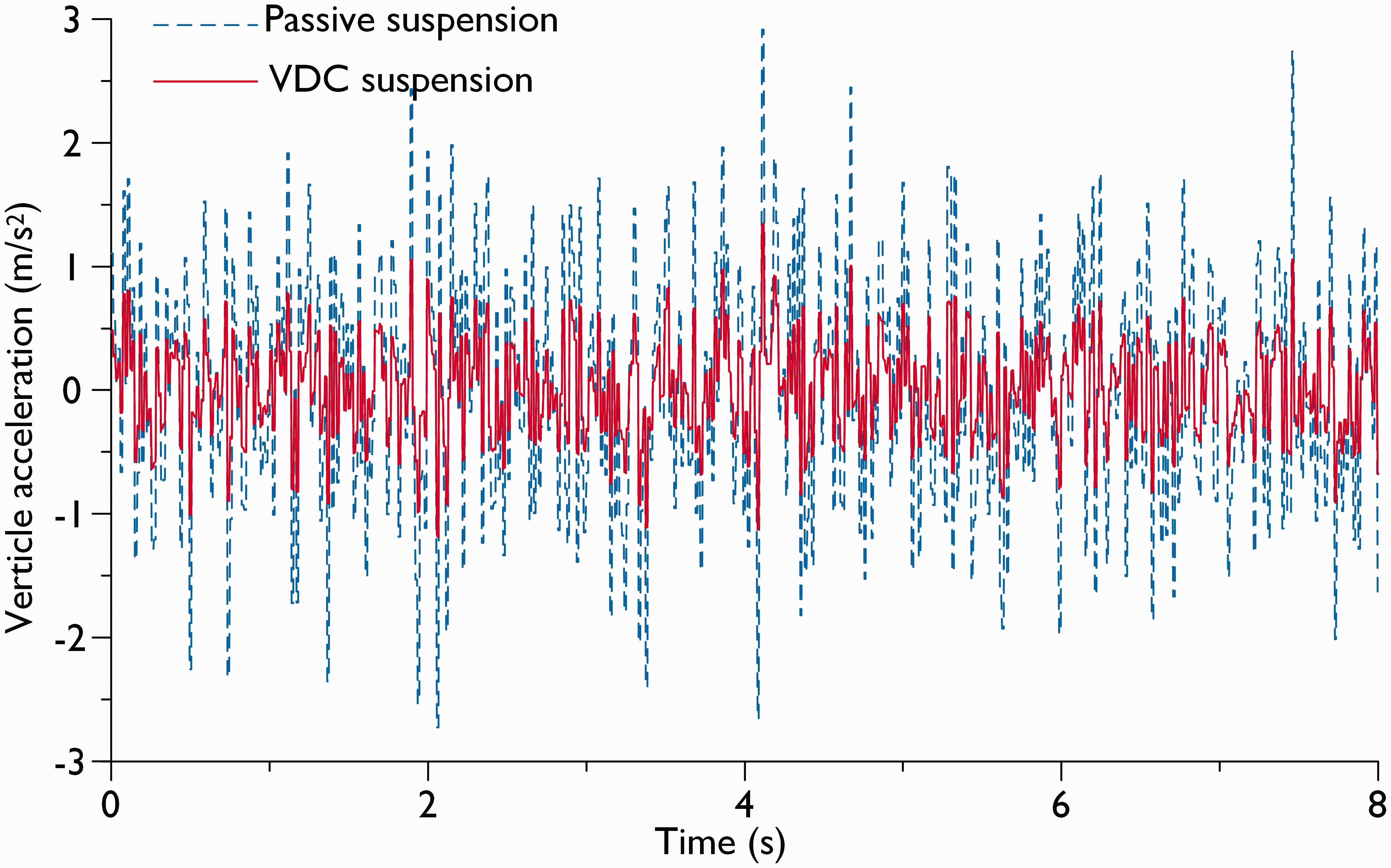
Vertical acceleration of the vehicle body.
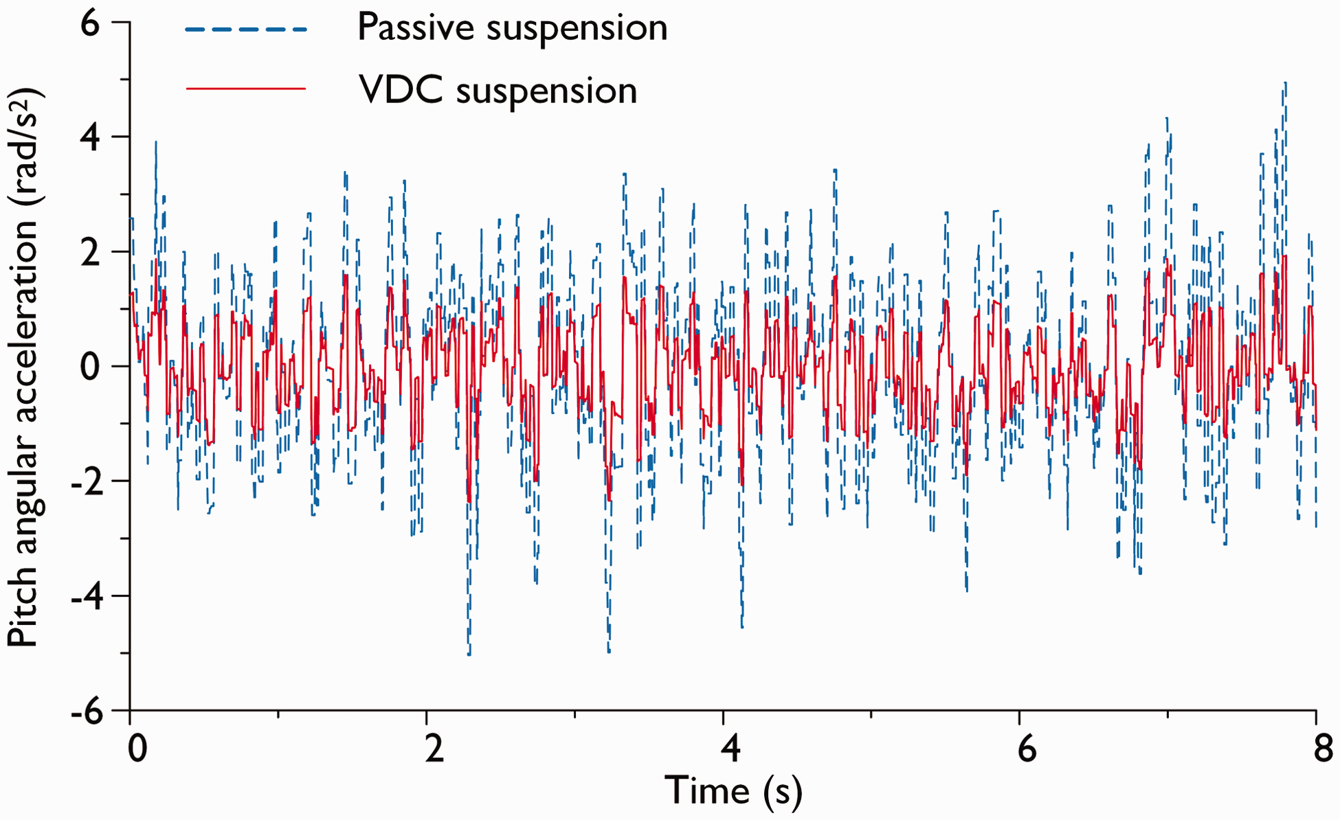
Pitch acceleration.
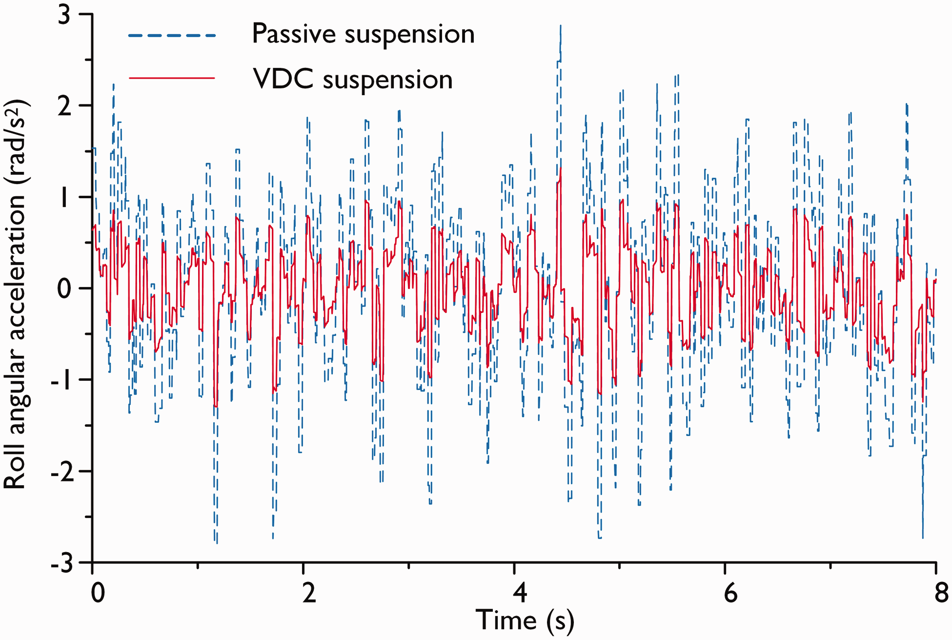
Roll acceleration.
In Figures 14 and 15, in the front axle, the suspension deflections on the left and right sides are clearly lower in the VDC suspensions than in the passive suspension system. In Figures 16 and 17, in the front axle, the tire deflections on the left and right sides are evidently lower in the VDC suspension than in the passive suspension system. The results show that the VDC suspension can effectively reduce the deflection of suspension and tire, thereby improving handling stability.
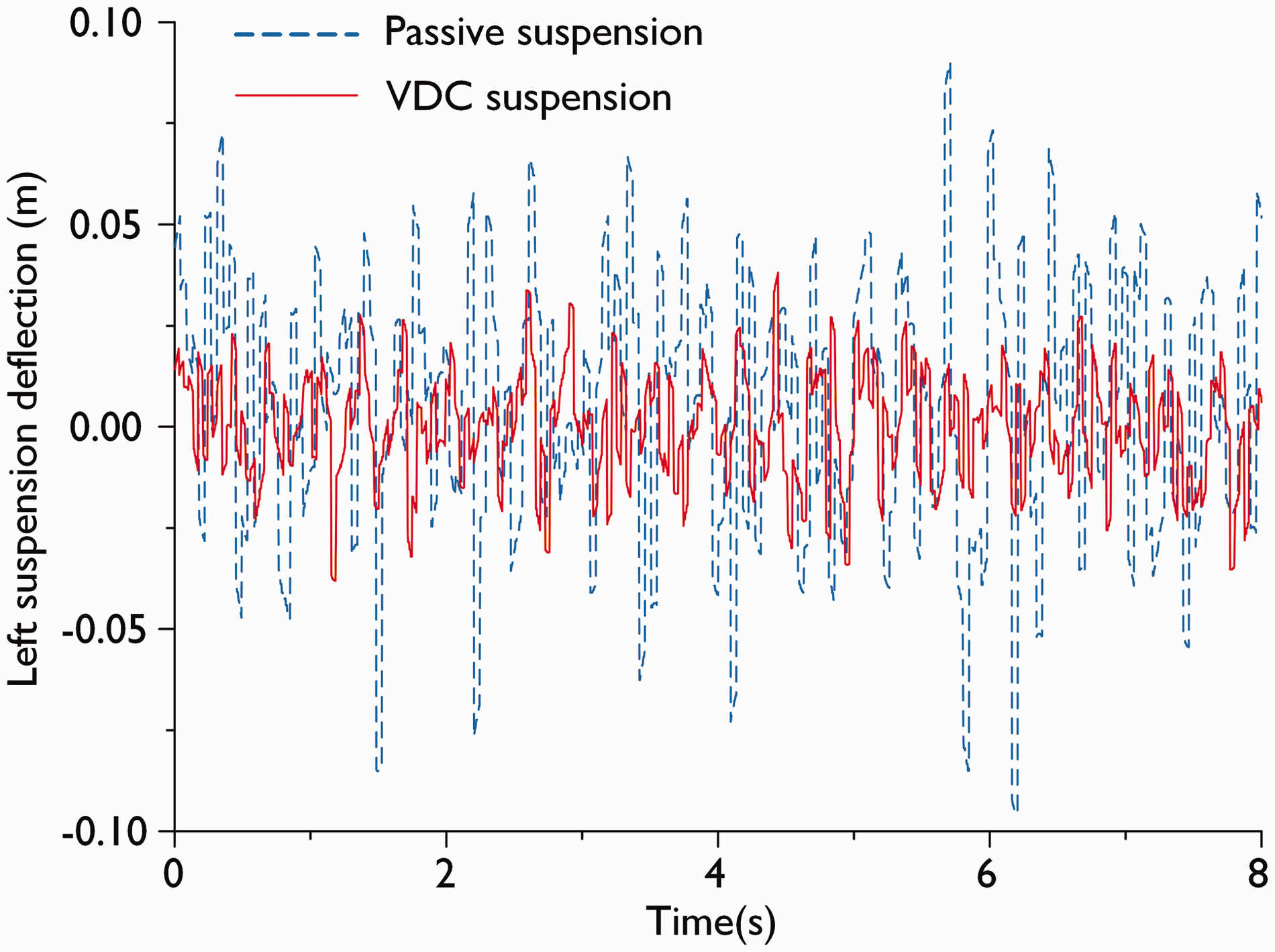
Deflection of the left suspension.
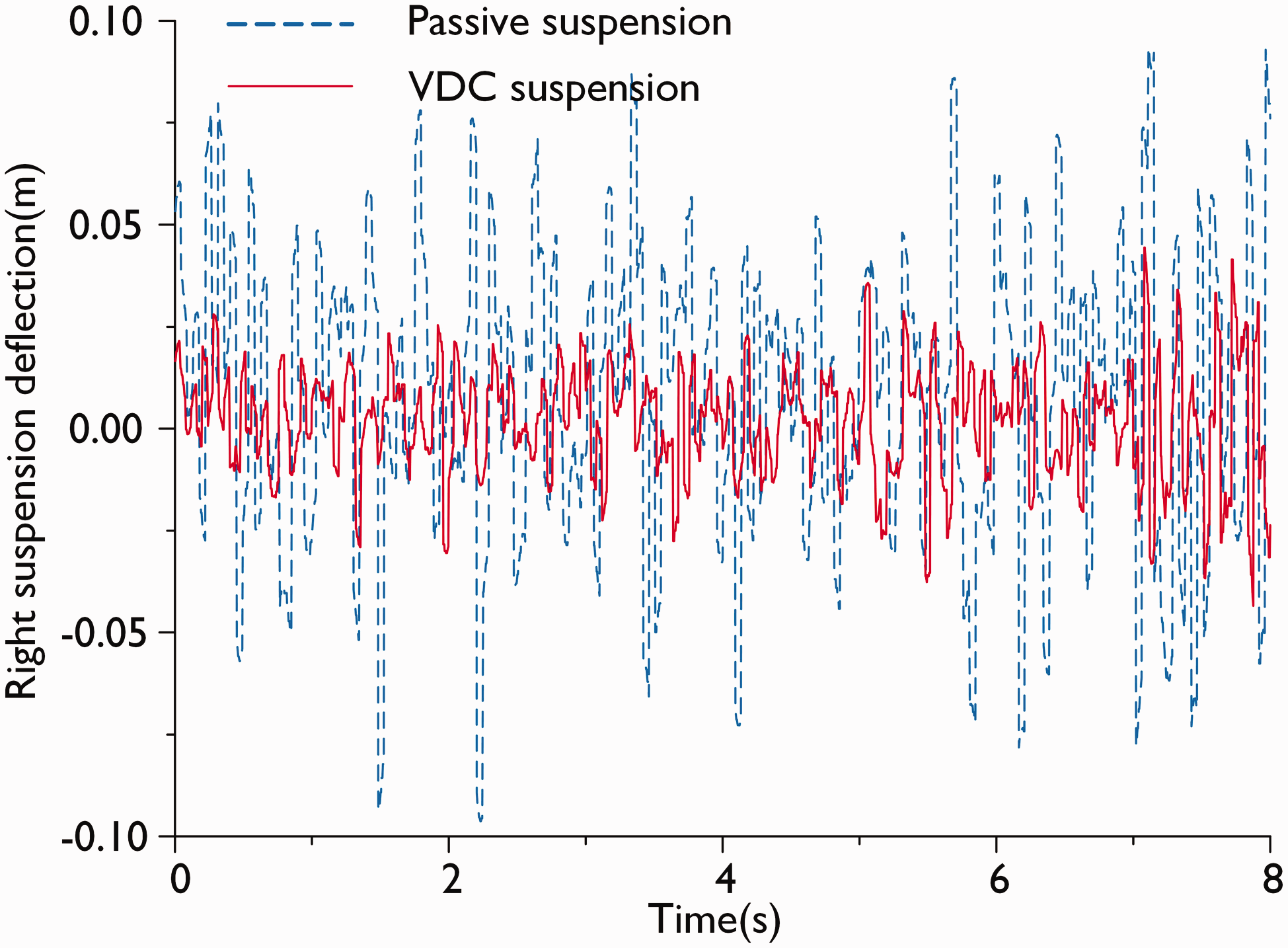
Deflection of the right suspension.
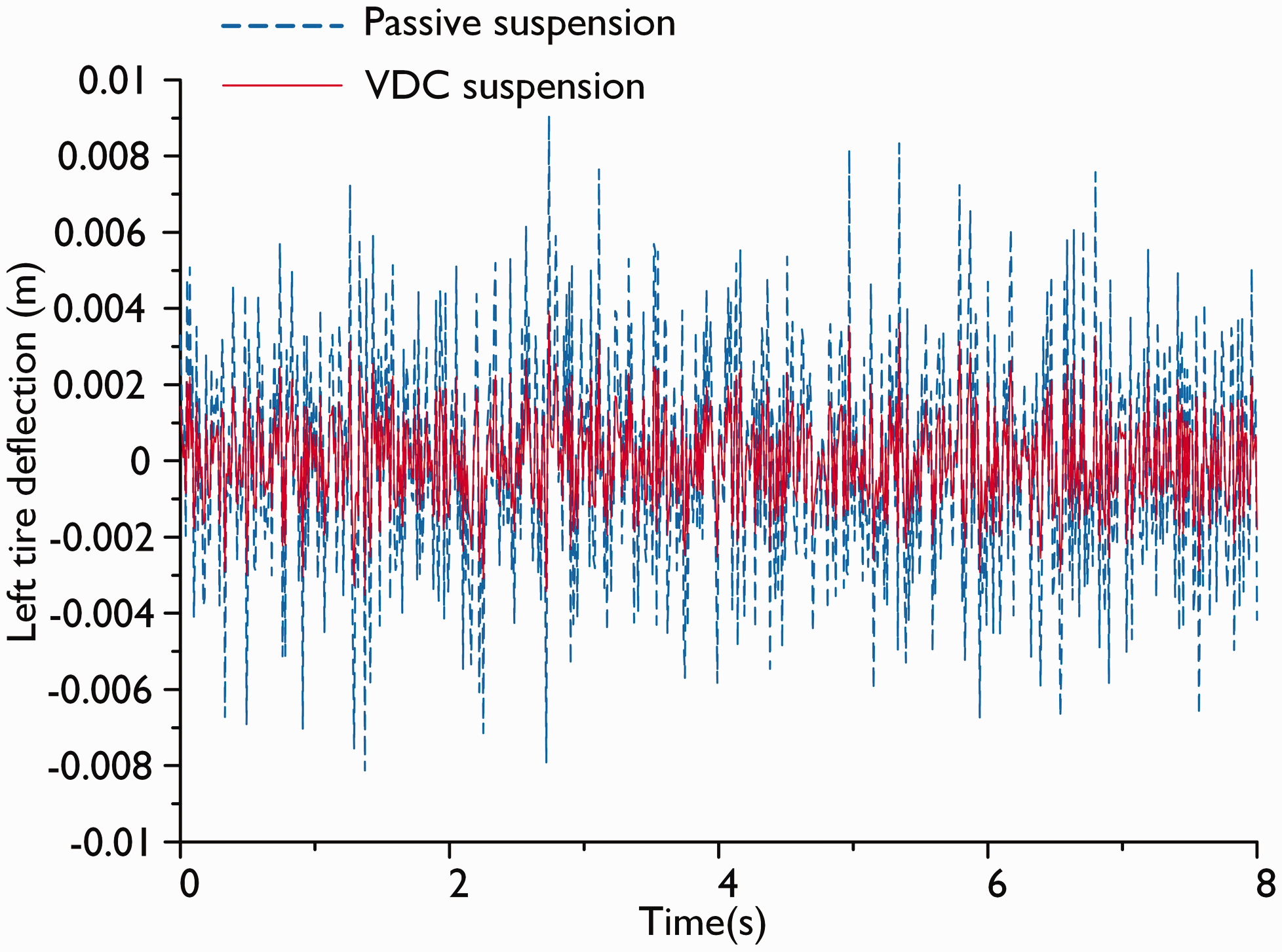
Deflection of the left tire.
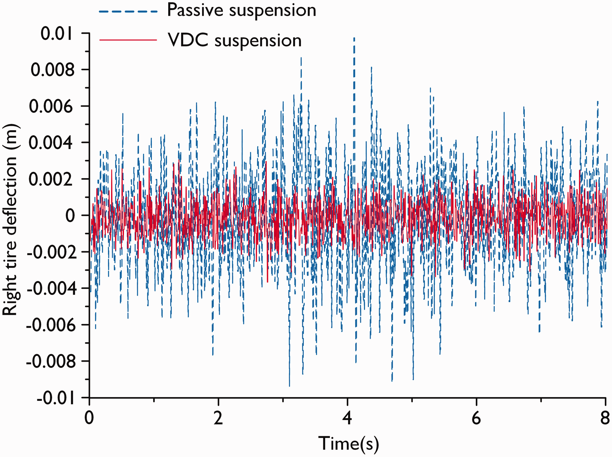
Deflection of the right tire.
To verify the control effects in the frequency domain, the energy spectral density figures of the vertical, pitch and roll accelerations of the two suspension systems are presented in Figures 18 to 20. In these figures, the amplitudes of the VDC suspension have been reduced considerably in comparison with those of the passive suspension.
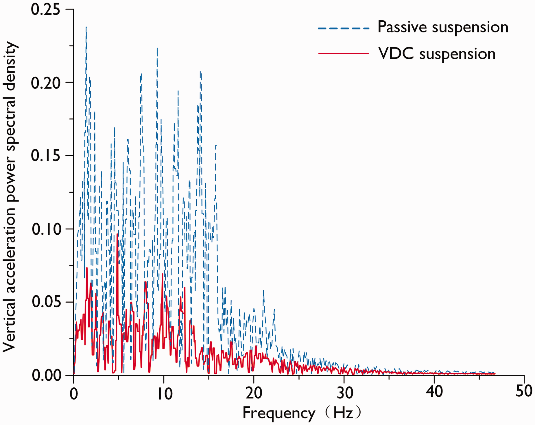
Vertical acceleration power spectral density.
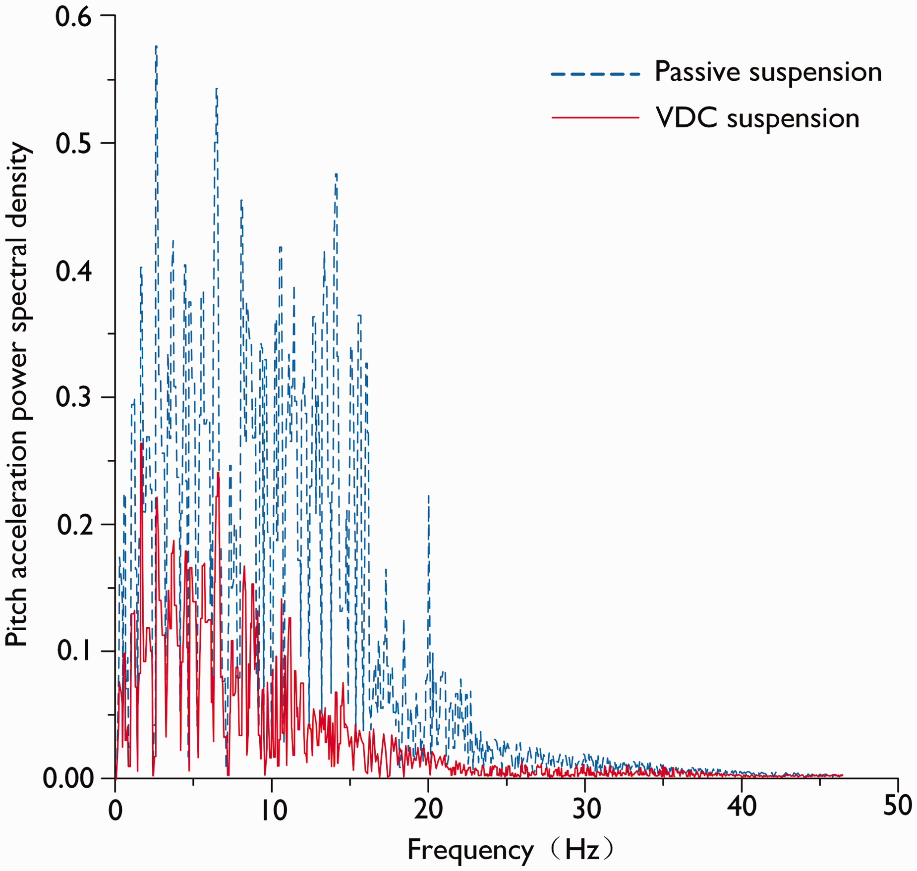
Pitch acceleration power spectral density.
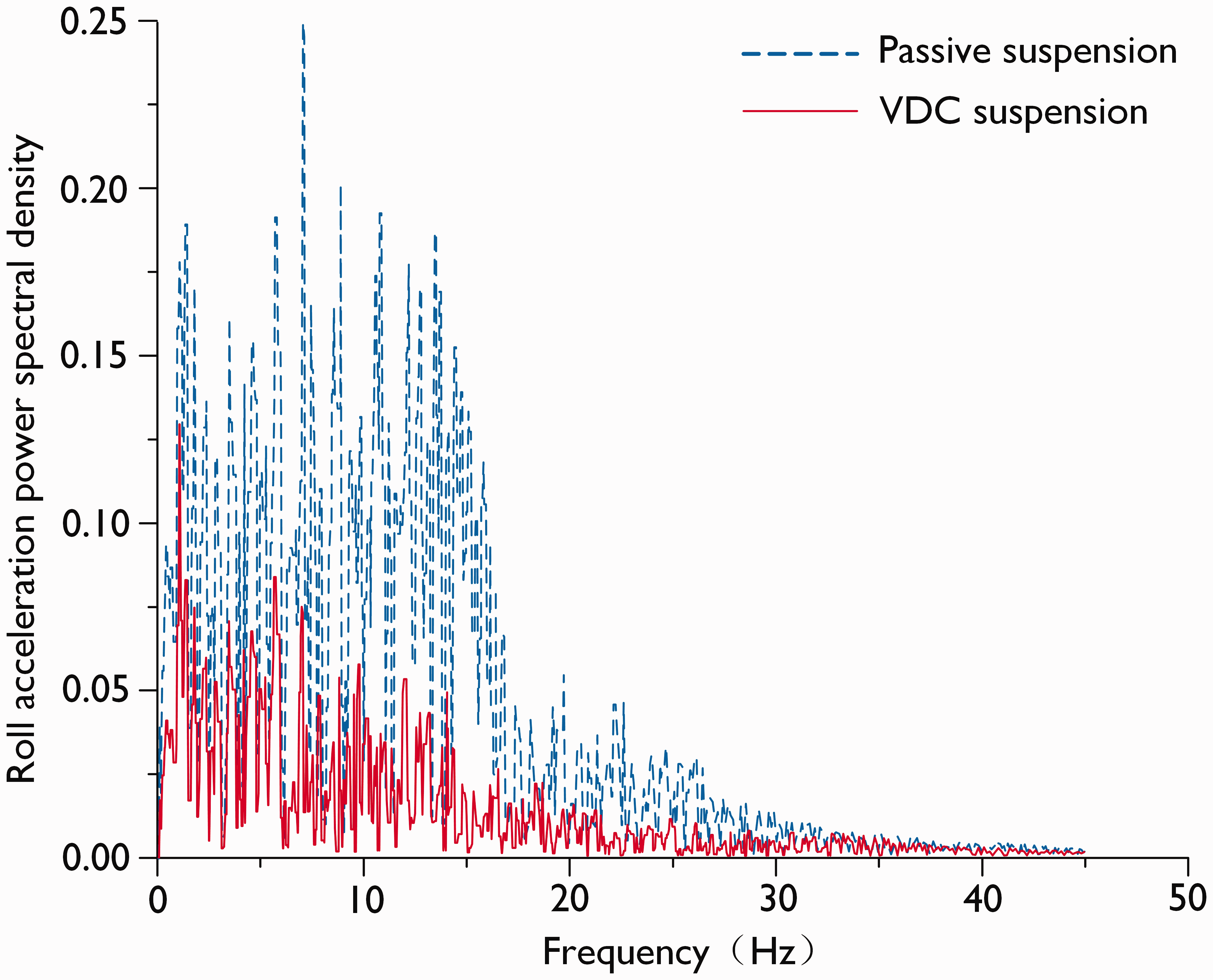
Roll acceleration power spectral density.
Conclusions
In this work, a 9-DOF model of a semi-active suspension system and a random input model of a road surface are established. These models provide a basis for vehicle control. A semi-active suspension with variable damping is proposed for heavy vehicles. The dynamic characteristics of damping and the time for establishing the damping force are presented on the basis of its working principle and configuration mechanism. A VDC strategy is proposed on the basis of the dynamic characteristics of a semi-active suspension with variable damping to control heavy vehicles. The results show that, in comparison with passive suspension, the VDC suspension can significantly reduce body, pitch angle and roll angle accelerations. Therefore, VDC suspension can considerably improve vehicle ride comfort and handling stability in comparison with passive suspension.
Footnotes
Declaration of conflicting interests
The author(s) declared no potential conflict of interest with respect to the research, authorship and/or publication of this article.
Funding
The author(s) disclosed receipt of the following financial support for the research, authorship, and/ or publication of this article: This work was supported by the National Key Research and Development Program of China (Grant No. 2016YFC0802900).