
Abstract
Over the last several years, the complexity of products has been increasing in parallel to the product cost thus becoming one of main focal points for development. On the other hand, although several applications struggle to fix vibration problems, highlighting the importance of damper design, literature that compares the benefits and disadvantages between of dry-frictional, viscous, and Coulomb–viscous dampers is still rare. Owing to this, the main goal of this work is to present a study that compares the dynamical response of mechanical systems against several damper types. For this research, we analyzed the effects of three types of damper (viscous, Coulomb–viscous, and dry-frictional dampers) on two mechanical systems. The first system consists of a mass-spring-damper with one degree of freedom, while the second system is a rotational machine with three degrees of freedom. The sensibility analyses of each damper were also studied, where the viscosity, Coulomb force, static friction, and Stribeck decay were the variables. In this work, mechanical systems were studied in a forced vibration condition and analyzed in the time and frequency domain in addition to identifying the main transfer functions in the frequency domain. In this analysis, the displacement, receptance, and force reaction were considered to be the study responses. After analyzing the main effect of damper coefficients on the general dynamic responses, we performed an optimization study in order to evidence the optimal configurations of either majorly viscous or frictional damper. Lastly, we analyzed the main behavior of this optimized damper on three-degrees-of-freedom rotational dynamic system.
Introduction
Over the years, the complexity of products has increased and the application conditions have become more severe. As a consequence, vibration issues have often been noticed along the product life-cycle. One example of this situation is the rotational machines, such as clothes’ washing machines. The occurrence of vibration issues in this sort of system might be explained by the essence of the dynamical efforts being harmonic. In addition, rotational machines are commonly submitted to unbalance forces, which amplify the occurrence of vibration problems.
In spite of the knowledge of the subject, studies that compare viscous and frictional dampers are rare. As a consequence, the development and selection of suitable damper parameters according to the design of machines are difficult. For that reason, the main goal of this work is to present a comparison between viscous and frictional dampers in addition to identifying the effect of each damper parameter for dynamical systems.
This work is divided in two parts, where the first part consists of the investigation of the effects of the main coefficients on a single-degree-of-freedom (DoF) system. In this study, the main goal was to identify the contribution of each damper parameter for the mass displacement and support reaction force.
In the second part of this work, we optimized the dampening system and identified two optimal solutions, one majorly viscous and other majorly frictional. The dynamical behavior of a rotational machine model with 3-DoF and unbalance mass was analyzed and the effect of these two optimal damper configurations was compared. It is important to note that these configurations were selected by the responses optimization, which were found in the first study. It demonstrates the usefulness of this method for design engineers.
In all the cases, the systems were submitted to forced vibration and dynamical responses were obtained in the time and frequency domains.
Because of the importance of this subject, several solutions and numerical models for hysteretic dampers have been developed over the years. Despite the high volume of concepts, we may characterize passive dampers into three categories: majorly viscous, majorly frictional, and frictional viscous, as presented in Figure 1.
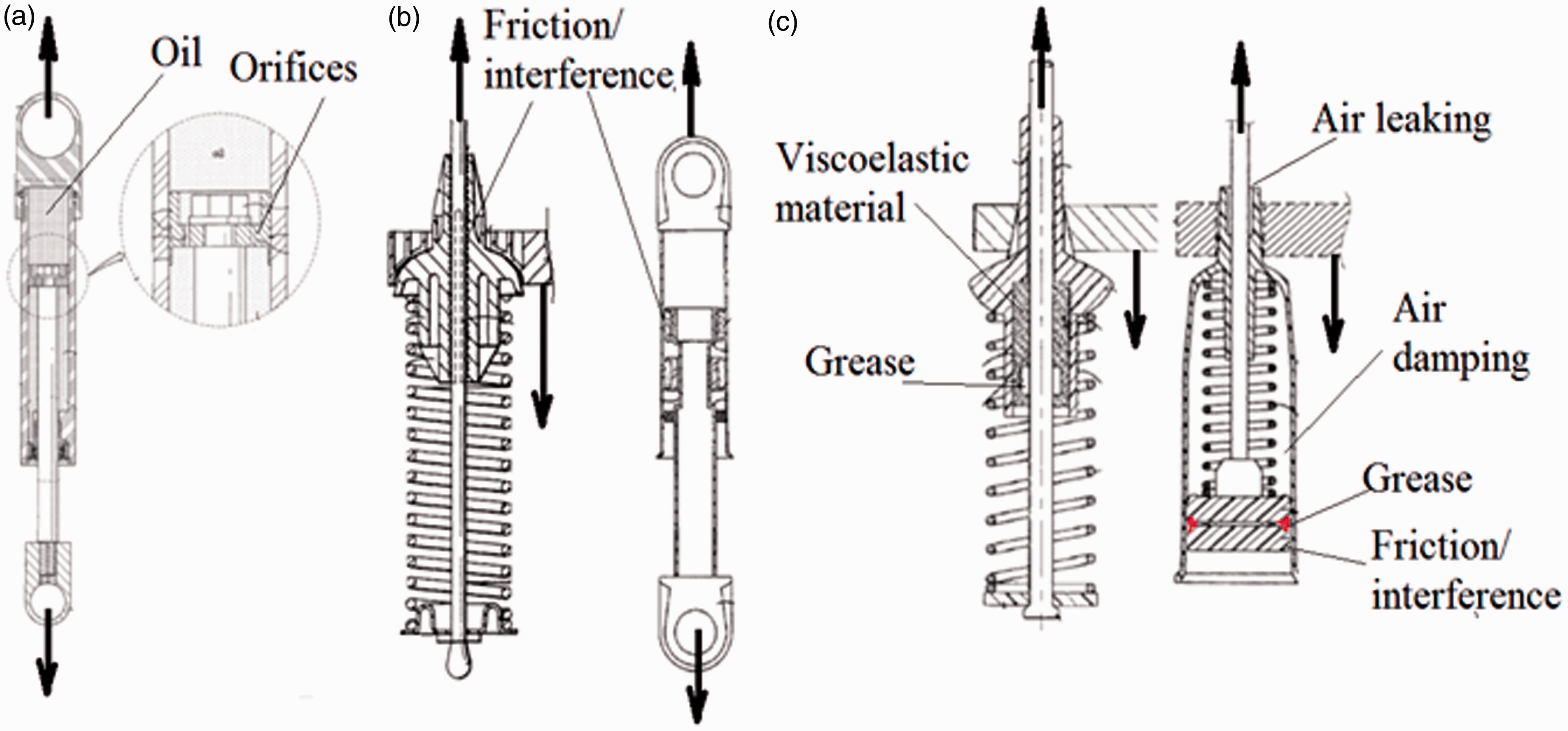
Example of majorly viscous (a), majorly frictional (b), and frictional-viscous damper (c).
Over the years, several models have been developed in order to represent the hysteretic behavior of dry-friction, frictional, viscous, and viscoelastic damping (Table 1).
Reference of numerical models for hysteretic dampers.
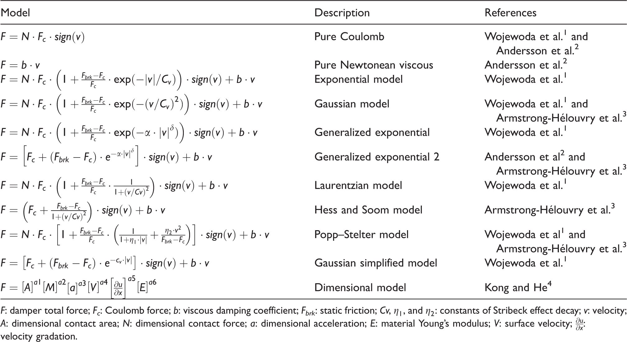
F: damper total force; Fc: Coulomb force; b: viscous damping coefficient; Fbrk: static friction; Cv,
New researches are constantly in development due to better understanding of the behavior of energy loss and damping in mechanical systems. We can highlight the study of Amjadian and Agrawal, 5 who identified frictional dampers whose variable coefficients are based on the electromagnetic effects. Yousefpour et al., 6 on the other hand, indicated the viscoelastic behavior of fabrics frictional dampers. Additionally, Zhang et al. 7 presented the inertial damper based on spherical particles. Another overview about viscous damping models can also be found in Akcelyan et al. 8
We can also identify new updates in several models, such as Xia et al. 9 presented a revised Bingham model to characterize semiactive vibration systems. Tokhi et al. 10 exposed the application of structural damping models for flexible manipulators. On the other hand, Oliveira et al. 11 presented the application of active vibration control based on magnetorheological dampers.
Among these models, we have selected the Gaussian simplified model for application in this work, and is as presented in equation (1). This model is interesting because it can represent Coloumb frictional, viscous, and frictional-viscous damper behavior and is based on only one constant of Stribeck effect decay

Another representation of this model can also be seen in Figure 2, where a graphic example of this numerical model is shown. In this figure, Fv is the effect of viscous force and Fs is the Stribeck force of the damping curve.
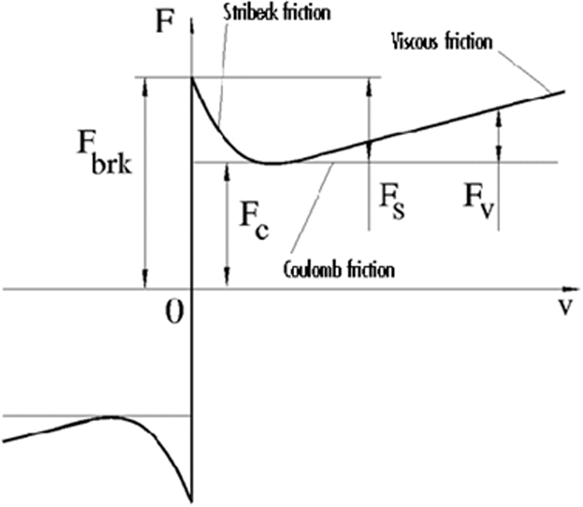
Graphical representation of generalized exponential numerical model of damping systems.
During the damper system design phase, several guidelines are recommended in order to better select and control the damper parameters. For example, static friction and Stribeck effect are directly correlated to system lubrication, 3 as presented in Figure 3. In this case, lubricant directly affects the damper behavior decreasing the static friction. 3
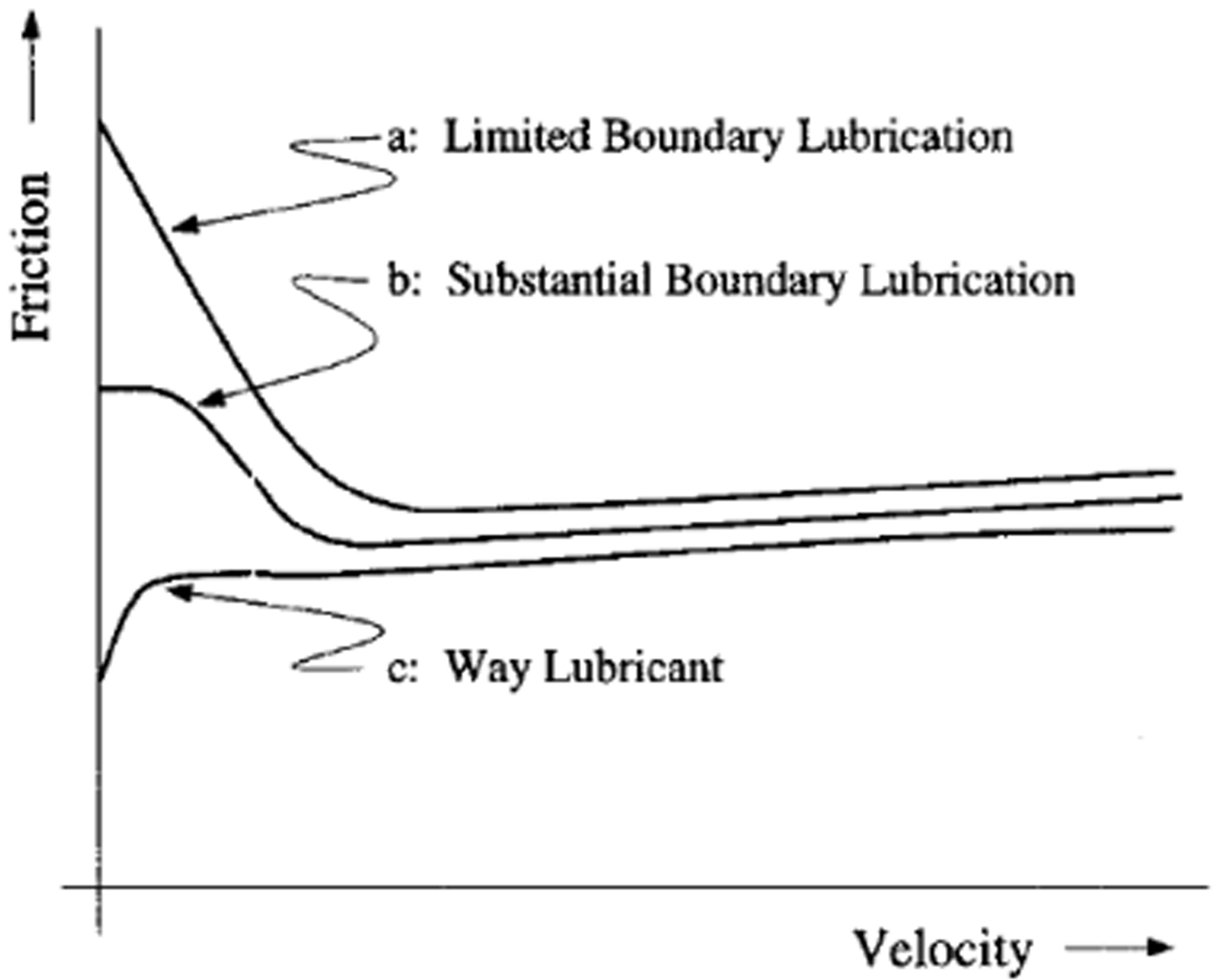
Example of effect of lubricant on static friction.
Another parameter that also affects the Stribeck effect and static friction is the grease viscosity that is used as the lubricant. In this case, thick solid greases are usually non-Newtonean fluids and cause yield strength in the beginning of the movement (e.g. when the grease is still cold), such as Bingham plastics.12,13 It is important to note that the viscous characteristics of dampening systems depends on the lubricant viscosity. Therefore, the proper lubricant selection is essential for suitably designing the dampening systems.12,13
On the other hand, Coulomb friction depends on the normal force applied on the surface, surface roughness, and material flexibility. Therefore, component interferences, roughness shape, and material selection are the basic parameters for proper designing of the dampening systems. It is also important to note that friction generally leads to wearing. And because of that, the dampening system property might vary along the life time.
The coefficient values need to be experimentally identified, in addition to the life-time strength and variation of properties over the time. In spite of that, this work is a useful tool for designing of the optimal dampening systems as a result of their effects on the dynamic behavior of mechanical systems.
After defining the numerical model to be used in this work, we define the boundary conditions and implement a transient numerical simulation in Matlab.
Material and methods
For the first study case, we analyzed the behavior of a single-degree-of-freedom system, where the mass, spring stiffness, and excitation force were considered to be constants. The stiffness was defined as 3000 N/m while the mass was 5 kg, as presented in Figure 4. On the other hand, the excitation force magnitude was 10 N and the excitation frequency was 1.5 Hz.
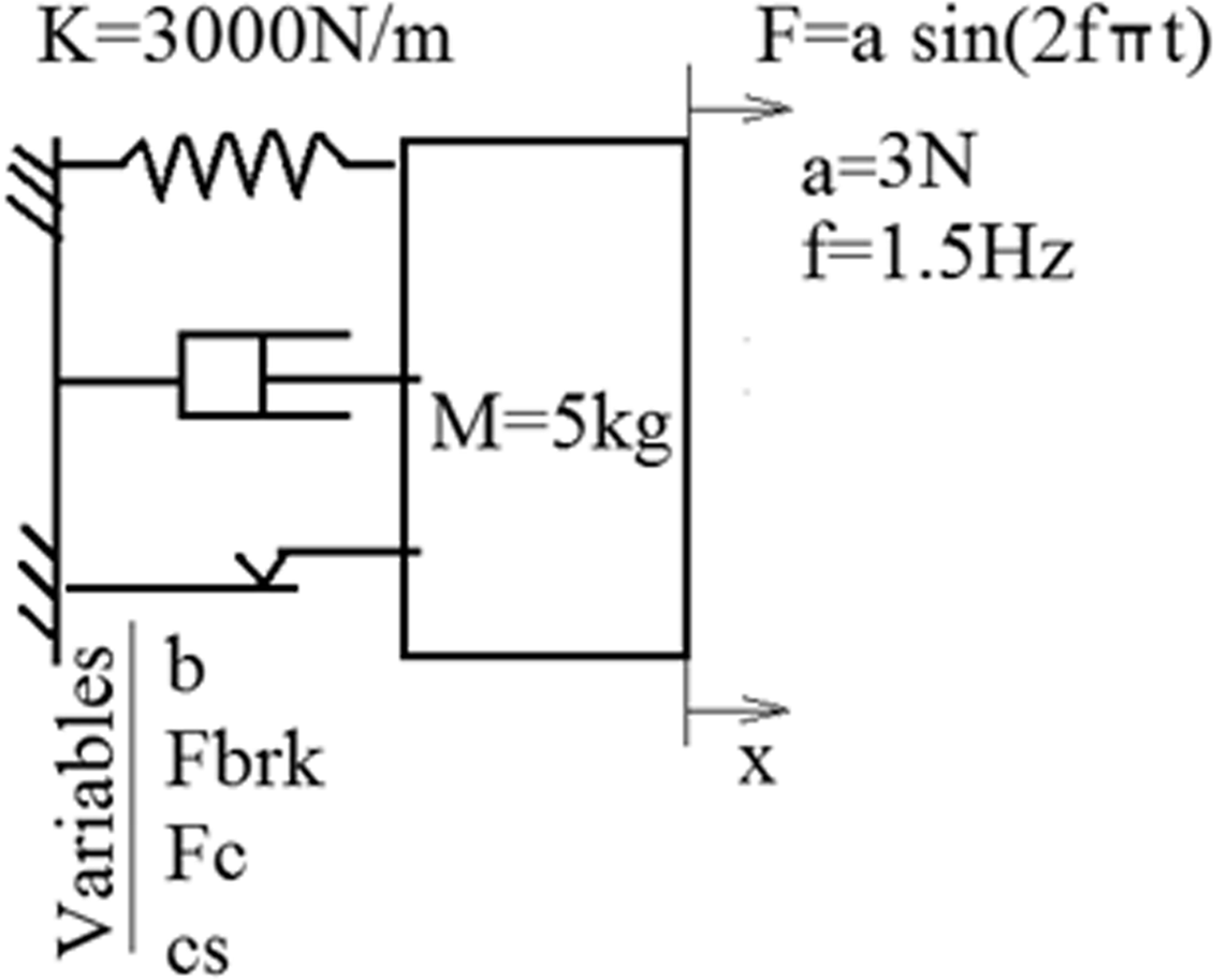
Schematic of 1-DoF mechanical system.
The numerical model, which were used for this analysis, is the generalized exponential that includes the viscous coefficient in the formulation. The movement equation considered for this system was

In this work, we considered that the viscosity coefficient (b), Coulomb force (Fc), static friction ratio (a) (
We have also selected values of Coulomb force and viscosity coefficient that imply the equivalent damping response against an impulse excitation, as exemplified in Figure 5. In this system, the mass is 15 kg and the stiffness coefficient is 3000 N/m. In this figure, it is possible to see that the peak of the system receptance occurs on 2.25 Hz and presents magnitude equal to 9 × 10⁻⁶ m/N. It is also possible to see that Coulomb force stopped the mass faster than the viscous damper, even though the Coulomb force generates residual forces in frequencies, which are different from the resonance frequency.
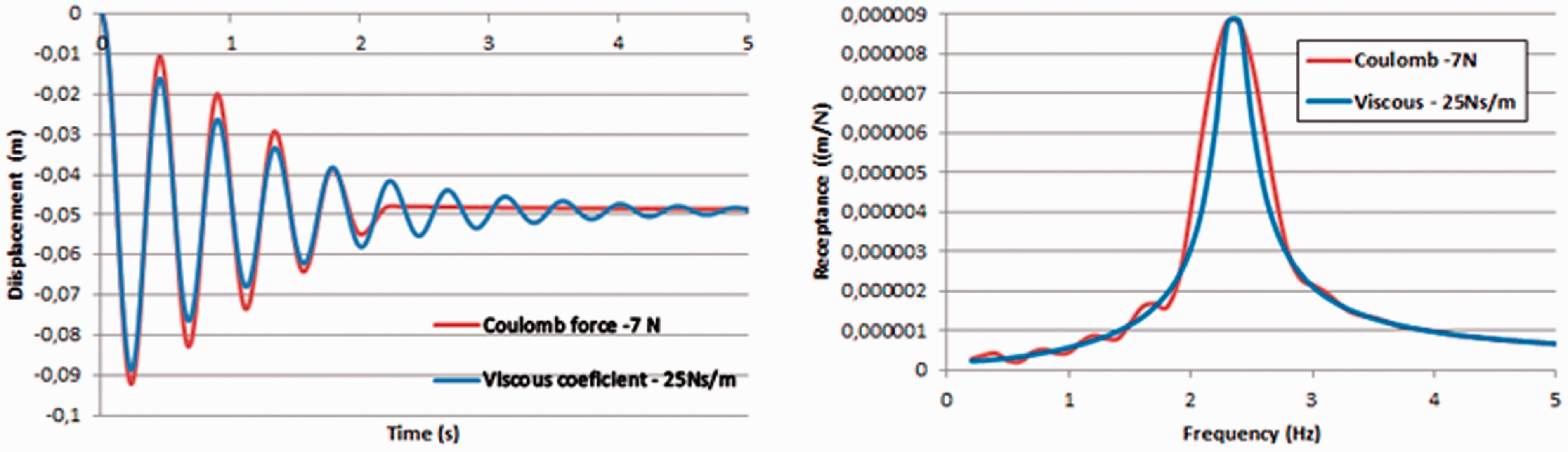
Comparison between pure viscous and pure Coulomb damping.
For the first study case, we used a multivariable method, which is known as the design of experiment. In Table 2, we present the design matrix, which considers four variable full design (2 4 ) with no central points. Besides the depiction variables, this table also presents the study levels and values of virtual study.
Virtual experiment design matrix and levels.
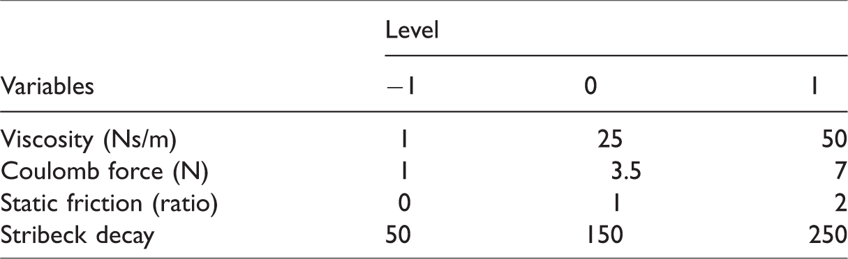
Another important point to be highlighted is that static friction ratio is a variable that is related to the Coulomb force. In this case, 7 N of Coulomb force and static friction ratio equal to 2 will result in a static friction force equal to 14 N.
For the second study case, we performed an optimization study in order to identify the optimum configuration for either majorly frictional or majorly viscous dampers. In this study, we assumed the minimization of displacement, maximum reaction force at 1.5 Hz, maximum reaction force apart from 1.5 Hz, and maximum receptance were the optimization objectives. Additionally, all these objectives were considered to have the same importance weight. Also, the minimum values of Coulomb force, viscous coefficient, static friction ratio, and Stribeck decay were defined as the optimization start values.
Minimizing

It is subjected to


where
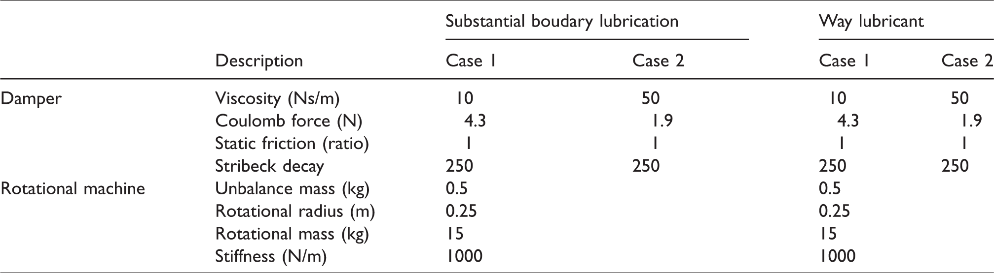
After identifying the optimized solution for majorly viscous and majorly frictional dampers, we implemented those dampers in a rotational machine model with 3-DoF in order to compare the dynamic behavior of the system against those damper types. Additionally, we analyzed the effect of lubrication on the system, comparing way lubricant (static friction ratio equal to 0.5) and substantial boundary lubrication (static friction ratio equal to 1).
In both cases, the systems were submitted to a rotational ramp, as presented in Figure 6. In addition to the rotation velocity per time, this figure also exposes a schematic of the 3-DoF system.
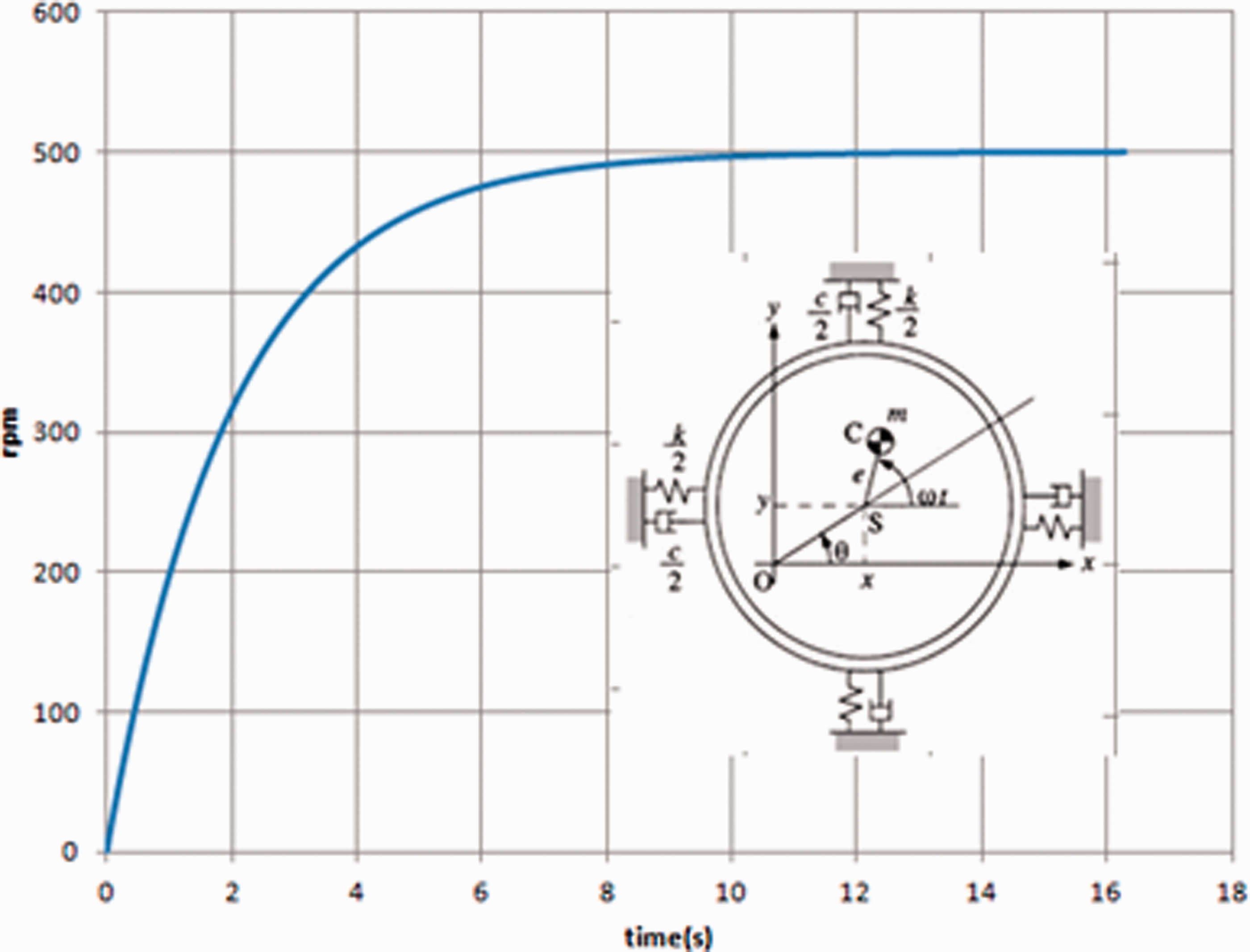
Scheme of 3-DoF system and excitation curve along the time.
The main values of the studied dynamic systems are as presented in Table 3, such as mass, rotational radius, unbalance, spring stiffness, and damper coefficients. The main responses that we analyzed in this second case were maximum orbit of the rotating part and maximum support reaction force.
Description of damper configuration and 3-DoF system parameters.
The numerical models and analyses were implemented in Matlab and the virtual design of experimental analysis was performed in Minitab statistical software.
Results and discussions
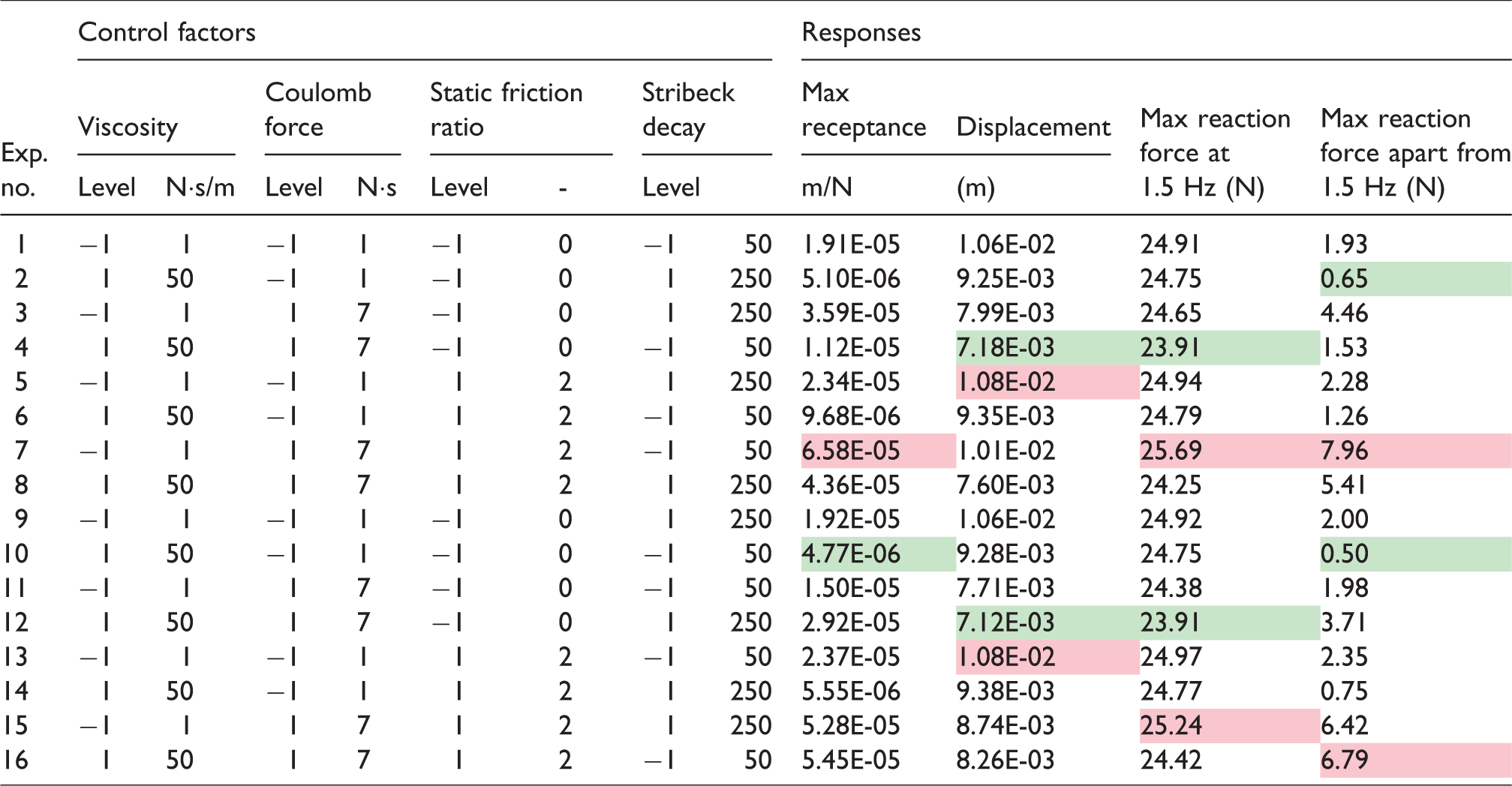
In this work, the difference between viscous and frictional damper was evidenced. The main analyzed responses are listed in Table 4, where the virtual experimental design matrix and responses are found. In this table, the maximum displacement and receptance were presented in addition to the maximum reaction force at excitation frequency (1.5 Hz) and maximum reaction force at different frequencies.
Virtual experiment design matrix and responses.
In Figures 7 and 8, we have also presented a graphical summary of those results. It is interesting to note that these charts correlate the damper force–velocity diagram with the mass displacement and receptance. The comparison between excitation force and reaction force is also present in these charts, evidencing “crisps”, which resulted in static friction.
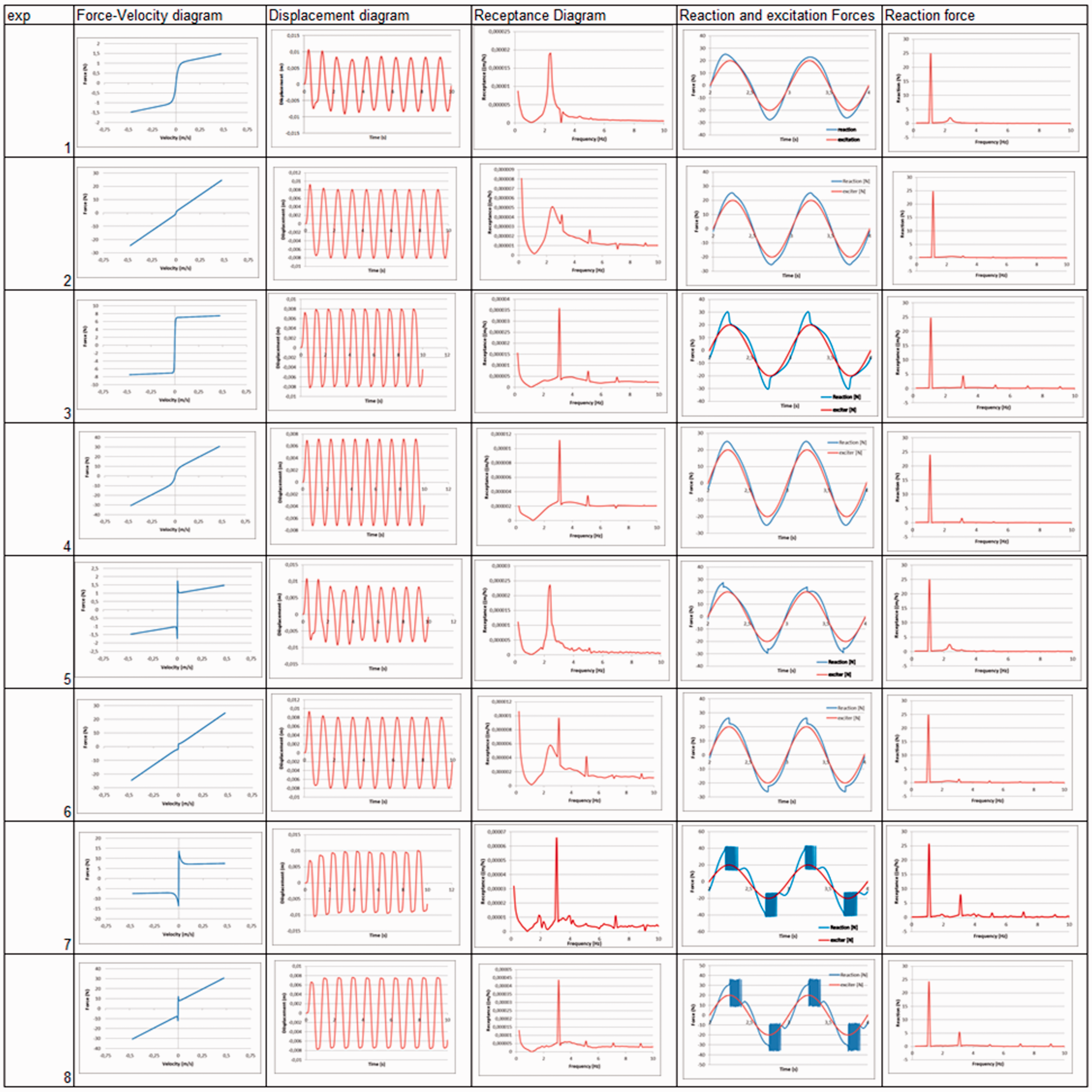
Comparison chart of the main graphical responses and variables.
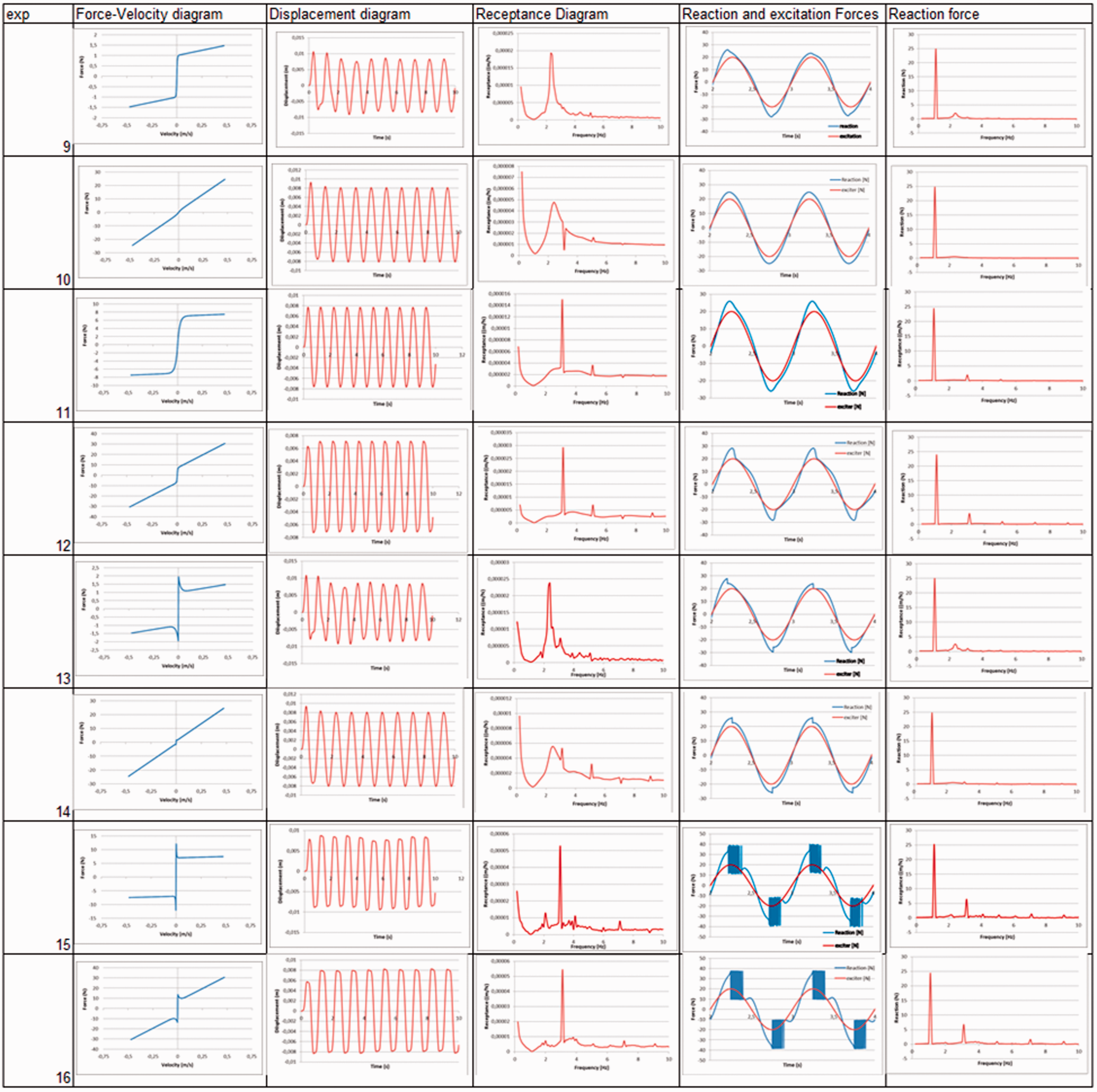
Comparison chart of the main graphical responses and variables.
In these charts, it is also important to note that the static friction implied on frequency components increased. Those frequency components might also result in noise and increased transmitted vibration, indicating potential vibration issues for the mechanical system.
For example, experiments 7 and 15 amplified the reaction force around 2.5 Hz. If the mechanics that supports this system has the resonance frequency around this value, the entire machine would be jeopardized.
On the other hand, the analysis of the whole receptance spectrum indicated that dampers with major frictional behavior might amplify and spread receptance responses at different frequencies.
In order to evidence the major contribution of viscous, friction, static friction ratio, and Stribeck decay on the studied system, we identified the main and secondary effects on the maximum displacement, maximum receptance, maximum reaction force at 1.5 Hz, and maximum reaction force apart from 1.5 Hz.
The main effects of the analyzed variable on the mean responses are presented in Figure 9, where the viscosity and Coulomb force were indicated to provide the highest effect on the maximum displacement. In both variables, the increase in values tends to decrease the maximum displacement of the system. Nevertheless, the increase in the Coulomb force was found to increase the reaction forces in frequencies apart from 1.5 Hz.
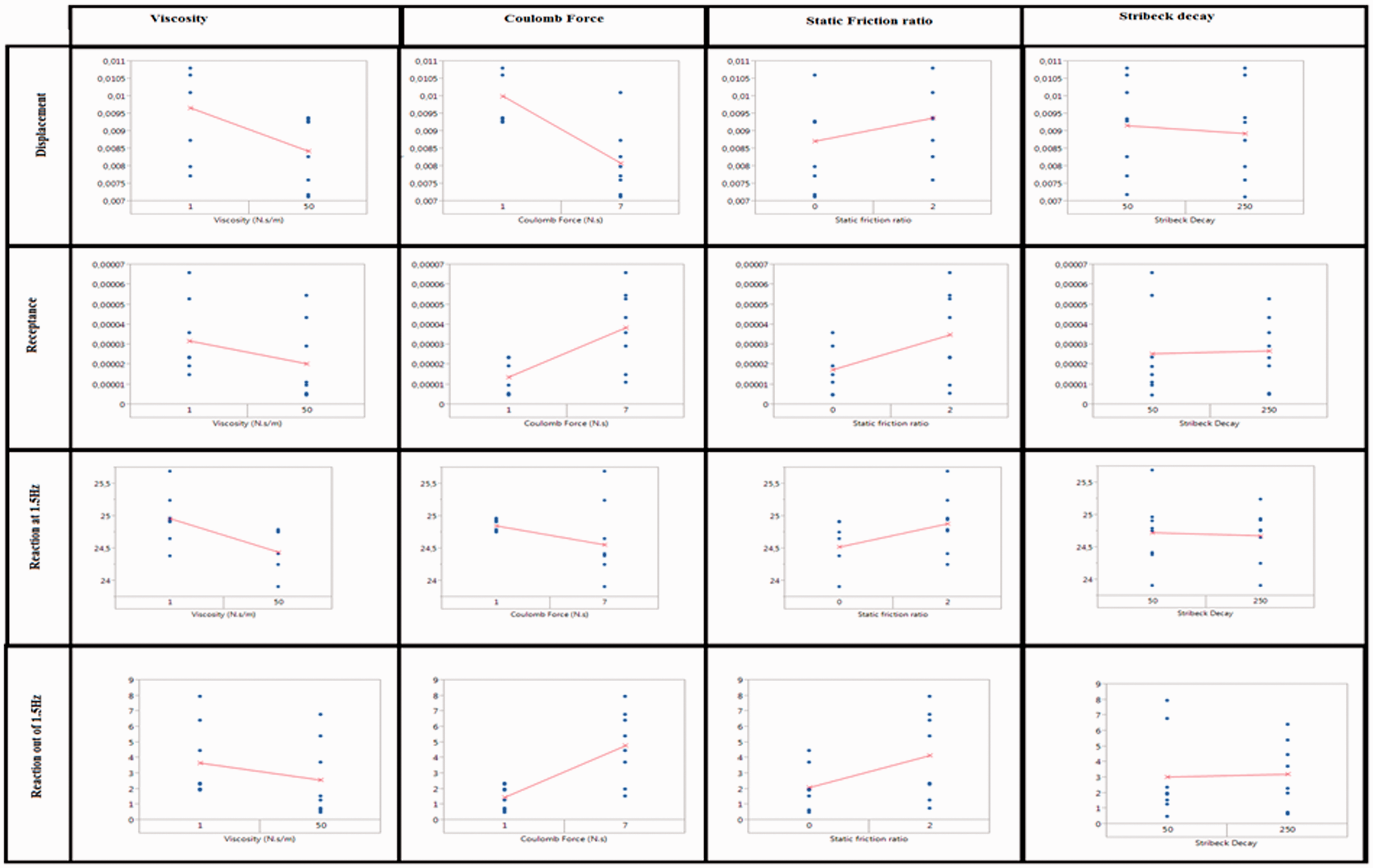
Main effect of variables on mean responses.
It is also important to note that the maximum receptance was mostly affected by Coulomb force and tends to increase in a direct proportion to that of the variable.
Another point that was also observed is that the highest levels of static friction ratio resulted in the increase of all mean responses.
Analyzing the variance of these responses (Figure 10), it is possible to see that the increase of Stribeck decay tends to decrease the displacement and receptance peaks when the static friction and Coulomb force are high. Otherwise, Stribeck decay will contribute negatively to the displacement control. In addition, any significant effect of Stribeck decay was observed for low levels of Coulomb force.
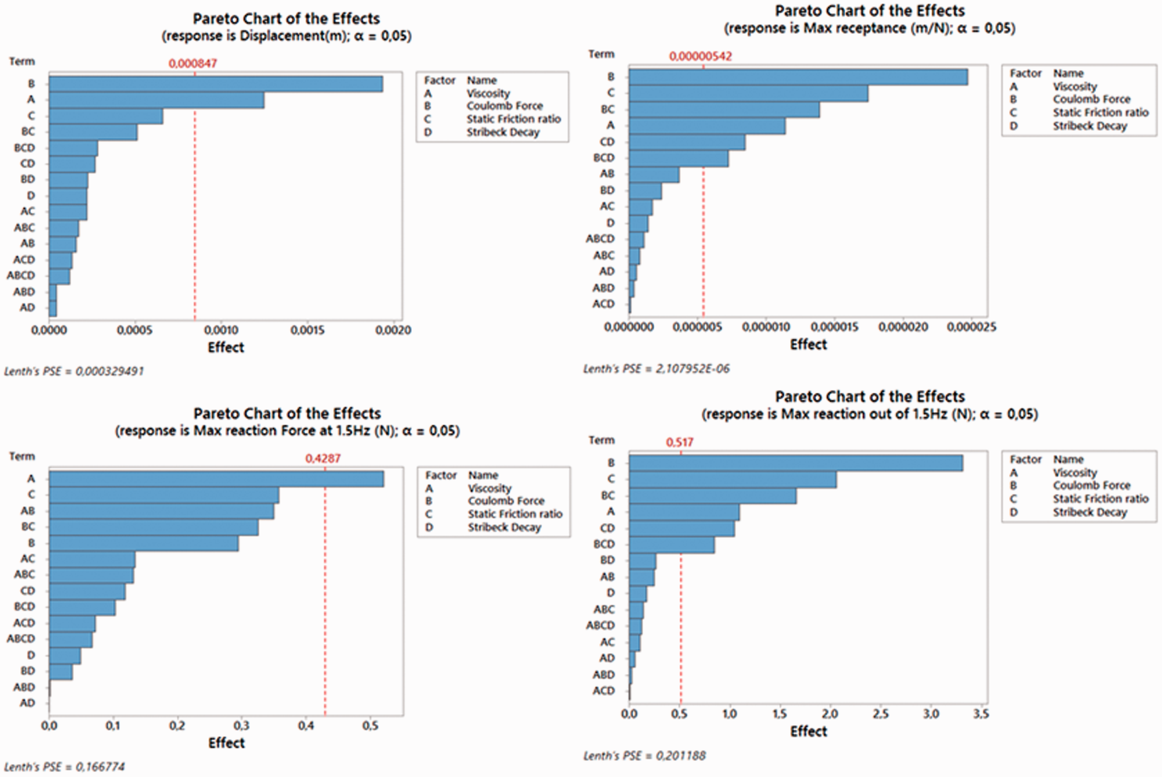
Pareto chart of the effects of viscosity, Coulomb force, static friction ratio, and Stribeck decay on the maximum displacement, receptance, reaction force at 1.5 Hz and maximum reaction apart from 1.5 Hz.
In Figure 10, it is possible to see that the viscosity is the variable that mostly affects the maximum reaction at 1.5 Hz. On the other hand, Coulomb force causes more effects on the maximum displacement, maximum reaction force, which is out of 1.5 Hz and maximum receptance. It is also possible to see that the Stribeck decay ratio is the second parameter that mostly affects the system.
With respect to the reaction force, the increase of Stribeck decay was seen to amplify the reaction force in several frequency components when the static friction ratio was low. It was also observed that low levels of static friction tend to reduce the reaction magnitude at excited frequency (1.5 Hz).
In addition to that, we also analyzed the contour diagrams of control factor on responses, as presented in Figure 11. In this figure, the combination of control factors and the result that those factors cause are graphically exposed. It is a powerful tool for design engineers for the selection of suitable damper coefficients for dynamical systems.
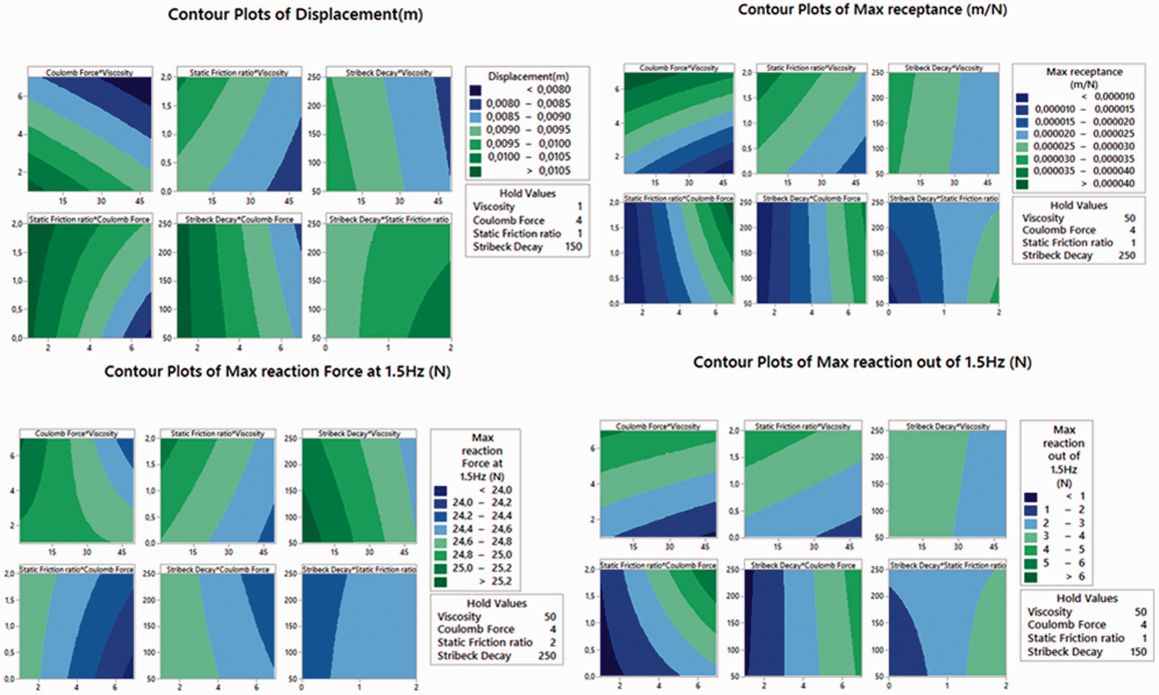
Contour diagrams of viscosity, Coulomb force, static friction ratio, and Stribeck decay on the maximum displacement, receptance, reaction force at 1.5 Hz and maximum reaction apart from 1.5 Hz.
According to Figure 11, the combination of high Coulomb force, high viscosity, and low static friction ratio implies the lowest displacement. In contrast to that, high Coulomb force increases the maximum system receptance.
With respect to the maximum reaction forces at 1.5 Hz, high Coulomb forces and high viscosities result in low reaction forces. However, high Coulomb forces imply increasing maximum reaction forces, which is out of 1.5 Hz.
It is also possible to see that high static friction ratio increases the reaction forces when Coulomb forces are high. Therefore, the most suitable situation for dynamic systems is to reduce the static friction ratio for increasing the system lubrication.
In summary, it might be said that viscous coefficient and Coulomb force were mainly responsible for the energy dissipation and control. Additionally, the static friction tends to affect the movement changes, and high level of this ratio generates impulse responses like in each reverse point. In the same way, Stribeck decay mostly controls the impulse such as intensity. For low levels of static friction, Stribeck decay presents a different role, controlling the response time of the system. In this way, high levels of Stribeck decay increase the constancy of the damping force.
The second study case resulted from the optimized solutions for majorly viscous and majorly frictional damper configuration, as presented in Figure 12. In both of the cases, we established two study conditions where the static friction ratio is equal to 1 in the first case and 0.5 in the second. Both of the optimized cases considered the maximum displacement target as 0.009 m.
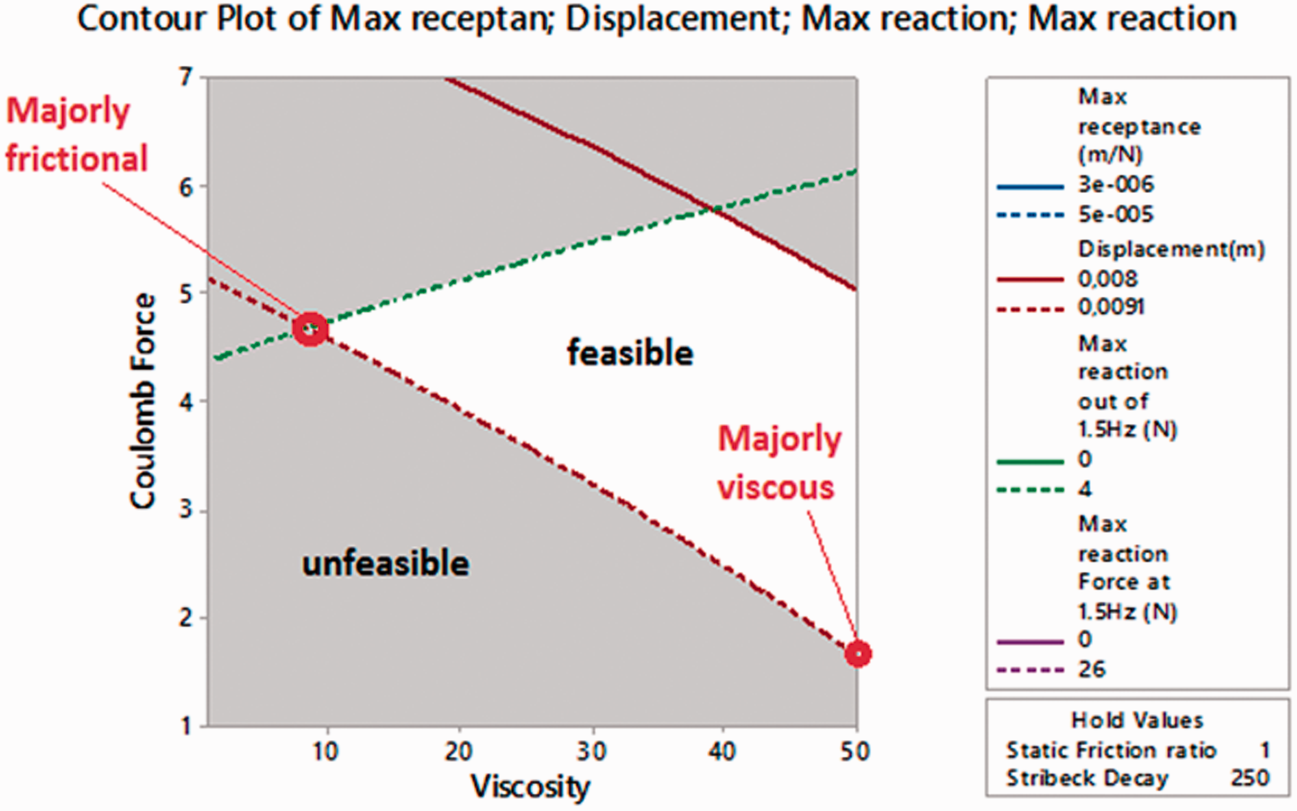
Overlaid contour diagram of viscous and frictional coefficient and indication of optimal solutions for majorly viscous damper with substantial boundary lubrication.
It is important to note that this optimization set creates a comparison metric for the 3-DoF system. Otherwise, it would not make sense to compare dampening systems, which imply different maximum mass displacements.
The velocity–force diagram of both majorly friction and majorly viscous damper can be seen in Figure 13. In this figure, both of the dampers have substantial boundary lubrication, implying the static friction ratio to be equal to 1.
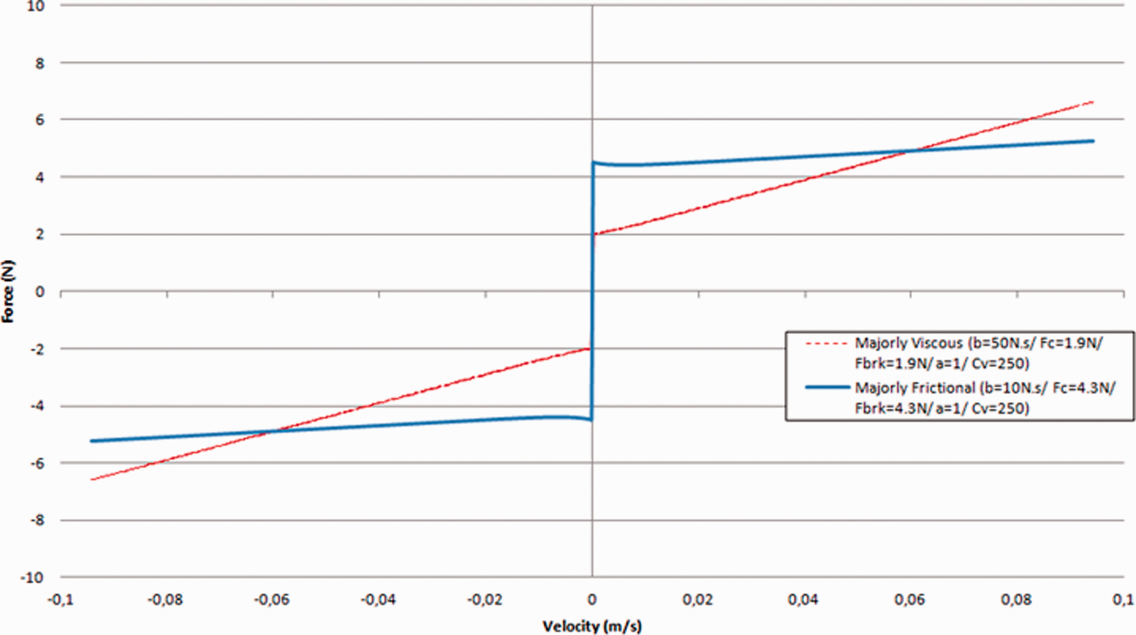
Comparison between velocity–force diagram of majorly frictional and majorly viscous damper with substantial boundary lubrication.
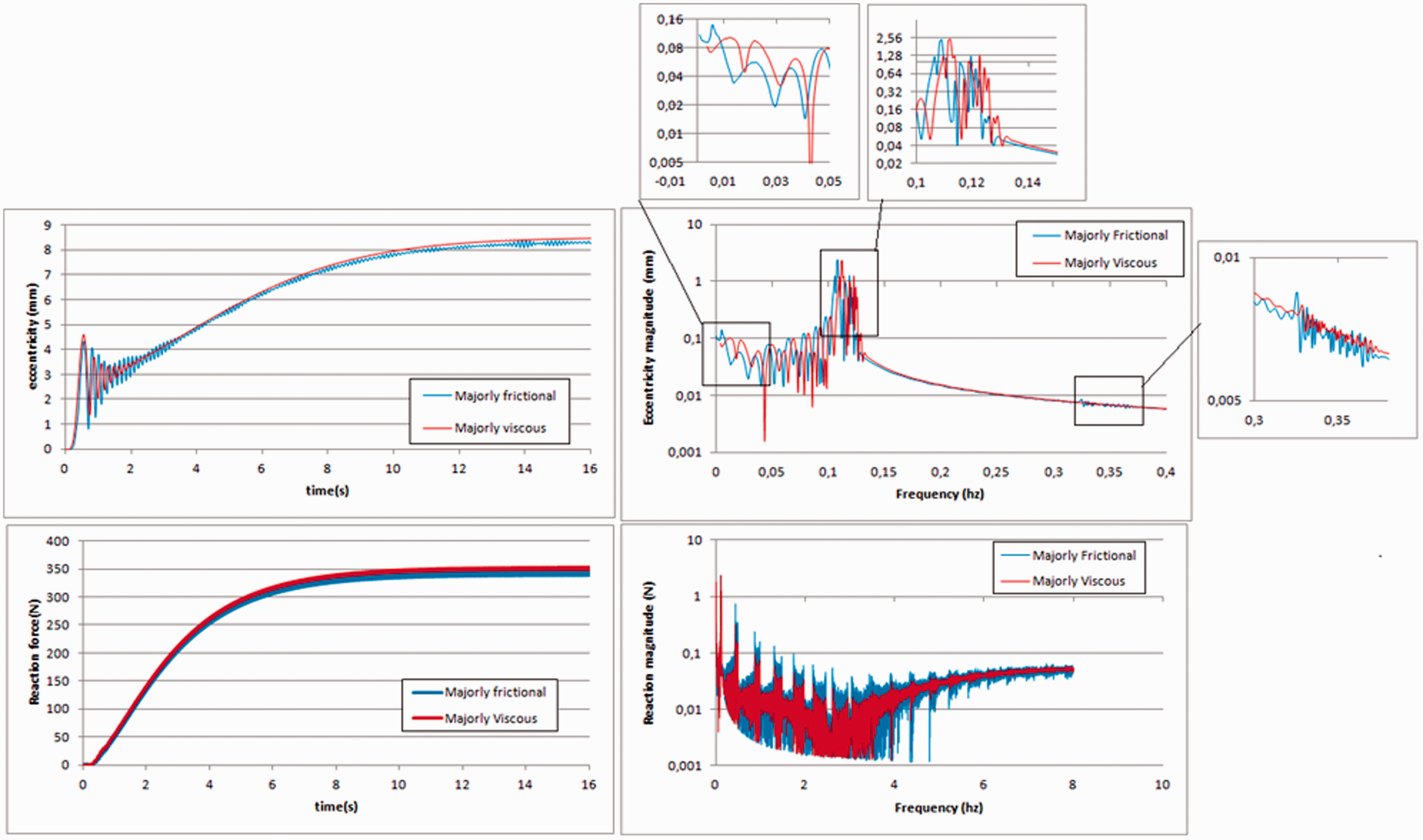
We analyzed and compared the eccentricity and absolute reaction force of 3-DoF rotational system in the time and frequency domain, as presented in Figure 14.

Comparison of eccentricity and absolute reaction force of rotational system with majorly frictional and majorly viscous dampers configurations, considering substantial boundary lubrication.
The analysis of displacement indicated that the majorly friction dampening system caused more noise than the majorly viscous system. In comparison, the second case implied smooth behavior and lower displacements. It is also possible to see that the frictional damper induced low frequency responses of the system, imposing an oscillation behavior in the eccentricity.
In the frequency analysis, majorly friction also induced more frequency components than majorly viscous damper, and the reaction response clearly indicated the potential noise issues in the support mechanism. It might indicate that viscous dampers tend to be more suitable to vibration absorption and isolation in machines than frictional damper with substantial boundary lubrication.
Another point that we could also highlight is that majorly frictional damper reduces the resonance frequency and amplifies support reaction effects. On the other hand, majorly frictional damper also causes more anti-resonances at low frequencies.
In order to evaluate the general effect of majorly frictional and majorly viscous dampers under way lubricants (Figure 15), we analyzed the transient behavior of the 3-DoF system under both the damper effects.
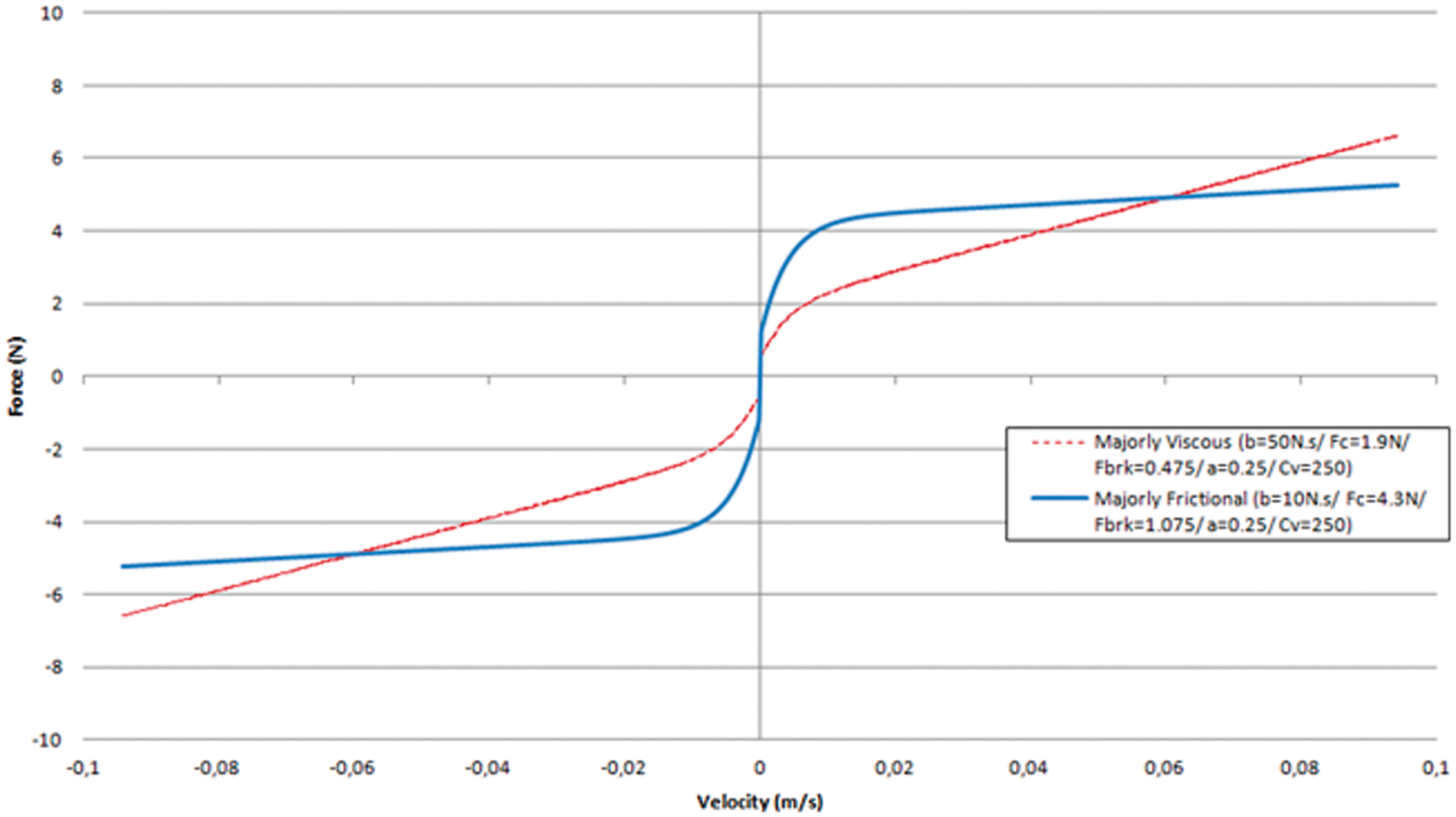
Comparison between velocity–force diagram of majorly frictional and majorly viscous damper with way lubricant.
In Figure 16, the analysis of the system displacement and reaction force over the time and frequency domain is presented. It is possible to see that friction reduces the resonance frequency, in addition to increasing the reaction forces. The secondary oscillation is also possible to be seen, even though it is less accentuated than the boundary lubrication.
Comparison of eccentricity and absolute reaction force of rotational system with majorly frictional and majorly viscous dampers configurations, considering way lubricants.
Moreover, we can identify the main differences between majorly frictional and majorly viscous dampers, in addition to producing a method to optimize the damper design parameters. Therefore, we can determine a suitable damper apart from the main damper behavior (viscous or frictional).
Conclusions
In this work, the comparison between viscous and frictional dampers was exposed and the effects of main coefficients of the numerical model of viscous-frictional damper were found.
The viscous coefficient and Coulomb force were found to be the most important variables of dampers. The static force ratio and Stribeck decay were found to promote different roles according to the level of Coulomb force and viscous coefficient.
It was evidenced that the static friction tends to increase reaction forces in the entire frequency spectrum and peaks of forces in different frequency components.
Comparing the behavior of the damper configuration, which resulted in the worst and best displacements, it was observed that the worst case was majorly frictional, and the best was viscous. The dynamic behavior of the rotational system in which the frictional damper was applied indicated excess of vibration in addition to excess of residual forces and noise at the support.
In conclusion, it might be pointed that dampers that are predominantly viscous tend to result in a smooth system response and might be more suitable to isolate and absorb machine vibrations.
Footnotes
Declaration of conflicting interests
The author(s) declared no potential conflicts of interest with respect to the research, authorship, and/or publication of this article.
Funding
The author(s) received no financial support for the research, authorship, and/or publication of this article.