
Abstract
One of the key challenges with the development of hybrid electric vehicles is the noise, vibration, and harsh behavior, specifically the uncomfortable ride experience during launch. This paper focuses on the driveline vibration caused by the quick response of the traction motor in the launch condition of hybrid electric vehicles. A torsional vibration differential equation for frequency analysis, including a Ravigneaux planetary gear set, a reducer, a differential, half shafts, and wheels, is thus built. Based on the equation, many components of the power-split system are simplified to make the controller design easy. Finally, wave superposition control strategy has been proposed to suppress the vibration, in which the concept is delaying part of the input to superimpose with the original input to eliminate the output wave. In order to optimize the control effect, parameters of the controller are chosen according to the system response. The simulation outcomes demonstrate that wave superposition control strategy is effective in attenuating the vibration generated by hybrid electric vehicles during launch conditions.
Keywords
Introduction
In order to meet with increasingly strict emission regulations, vehicle manufactures spare no efforts to develop electric vehicles. However, current battery technology does not sufficiently satisfy the needs of the vehicle, so hybrid electric vehicles (HEVs) will surely dominate in the present stage. Nowadays, people are paying more attention to the noise, vibration, and harshness performance of a car. In the pure electric mode of an HEV, the engine does not engage in torque output. Due to the quick response of the electric motor, it is easy to activate driveline vibration, in which low frequency longitudinal vibration occurs in the range of 2–20 Hz.1–3 Thus, it is essential to suppress this driveline vibration during HEV development.
During the last decade, a considerable amount of research regarding this issue has been carried out. Fredriksson et al. 4 designed PID, pole placement (PP), and linear–quadratic–Gaussian controllers for active cancellation of the torsional vibrations. The PP controller was applied to solve driveline vibration problems of HEVs during engine starts and stops5–7 and oscillations in the driveline caused by elasticity and gear play. 8 A well-performing motor can also help attenuate system vibration.9,10
However, there is very limited published work available on the active control of driveline vibration of the Ravigneaux planetary power-split HEVs. Furthermore, most methods mainly focus on the vibration problems in EVs or conventional sedans instead of those in HEVs. Therefore, this paper focuses on eliminating the driveline vibration in the transmission system of the Ravigneaux planetary power-split HEVs. In this article, the structure and the working principle of a Ravigneaux planetary power-split HEV are introduced, and a mathematical model of this system is established. Based on this model, natural frequencies of the power-split system are calculated. According to the natural frequencies, the model is simplified to satisfy and optimize the active controller. The control principle of wave superposition control strategy (WSCS) is next illustrated in detail. Finally, WSCS is applied in the active control of driveline vibration during launch conditions.
Dynamic modeling of the power-split system
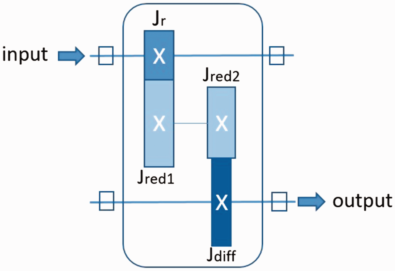
Due to the need for understanding the transient behavior of the Ravigneaux planetary power-split system during launch conditions and providing support for future control designs, a model is required to characterize the relevant system dynamics. The Ravigneaux planetary power-split hybrid transmit system, as shown in Figure 1, is made up of the electric motors MG1 and MG2, Ravigneaux planetary gear set, reducer, differential, half shafts, and wheels. The engine does not work in launch condition, so it is locked in the model.
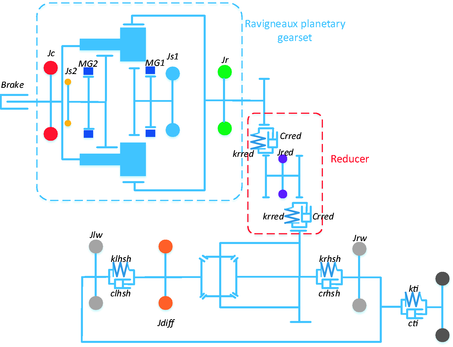
Configuration of the HEV powertrain.
Ravigneaux planetary gear set
The core component of the power-split hybrid system is the Ravigneaux planetary gear set, as shown in Figure 2, which includes a carrier, sun gear 1, sun gear 2, planetary gear A, planetary gear B, and a ring. The planetary gear set provides interconnections for the engine and the two motors MG1 and MG2. The carrier is connected to the engine, while sun gear 1 and sun gear 2 are connected to motor MG1 and MG2, respectively. The ring is connected to the reducer, which is connected to the differential. Two wheels are connected to the differential on both sides. The Ravigneaux planetary gear set enables the power-split hybrid system to work in the pure electric or hybrid driving mode.
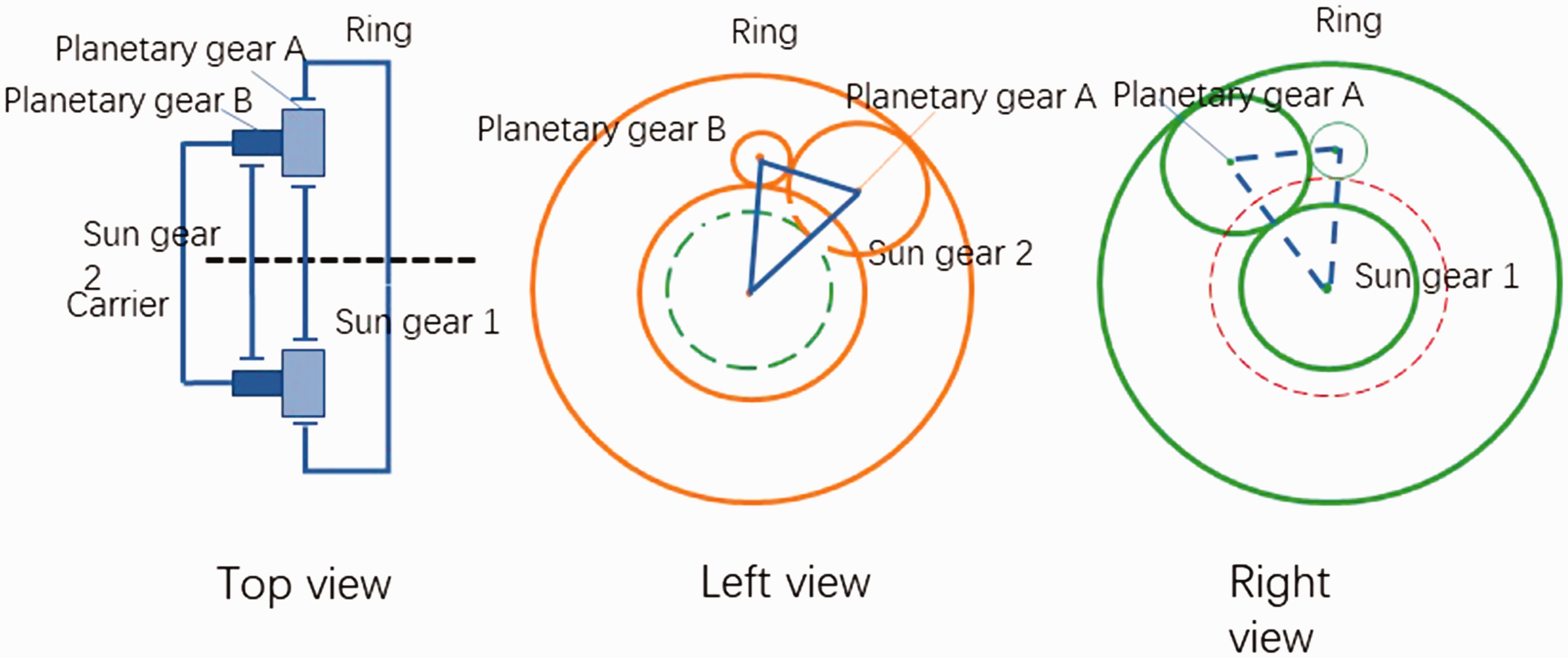
Structure of the Ravigneaux planetary gear set. (a) Top view, (b) left view, and (c) right view.
In the pure electric driving mode, the carrier is locked with the engine by an electro-hydraulic brake, while sun gear 2 and motor MG1 are in free state. Motor MG2 then drives the wheels through sun gear 2, planetary gear B, planetary A, the ring, the reducer, and the differential. As shown in Figure 3, according to the kinematics relationship of the compound planetary gear set, the rotational speeds of A and B on the rear planetary gear are as follows


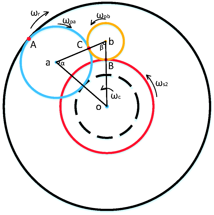
The kinematics analysis of the rear planetary gear mechanism.
The velocity of C on planetary gear A can be described as

The velocity of C on planetary gear B can be described as

Combining equations (3) with (4) gives

In addition, according to the geometric relationship of gear meshing and the cosine theorem


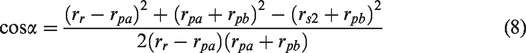
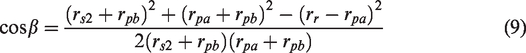
Substituting equations (6), (7), (8), and (9) into equation (5) gives

Combining equations (1), (2), and (10) gives
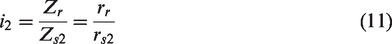

In equation (11),
The reducer and the differential
In order to make the controller design easy, some components of the system need to be simplified. The natural frequency characteristics of the system can determine which components are important to the active control of the driveline vibration. Components with natural frequencies far away from human sensitive frequencies are neglected. As presented in Appendix 2, the eigenvalue equation of the no damping system is

All calculation results of natural frequencies with the corresponding parameters presented in the Table 2 in Appendix 1 are shown in Table 1. These parameters can be obtained from either an experimental method or theoretical calculation.
Calculated natural frequencies.
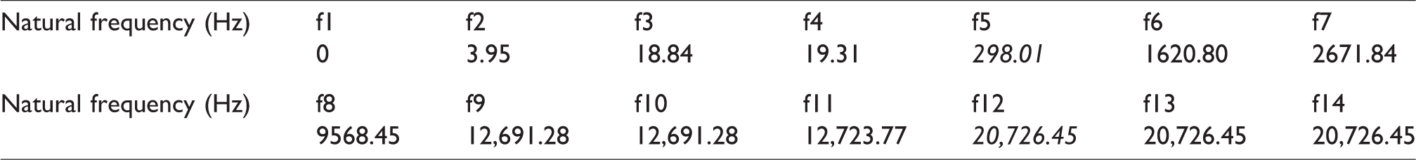
According to the results, the first three modals occur in the frequency range of 0–30 Hz, the range of frequencies about which people are sensitive. The gearbox vibrates obviously in first-order modal. The second-order modal can be considered as the right and left wheel modal. In third-order modal, only the car body vibrates a little.
The natural frequencies of the Ravigneaux planetary gear set are in the high frequency range mainly. For the sake of designing the active controller, the moment of inertia of the planetary gear is overlooked. The dynamic relationship of the Ravigneaux planetary gear set can be replaced by equation (12).
The natural frequencies of the reducer and the differential are high, which result in high meshing stiffness between them. As a result, the backlash and the static transmit error of gears of the reducer and the differential are overlooked and treated as rigid transmit. As shown in Figure 4,
The model of the reducer and the differential.
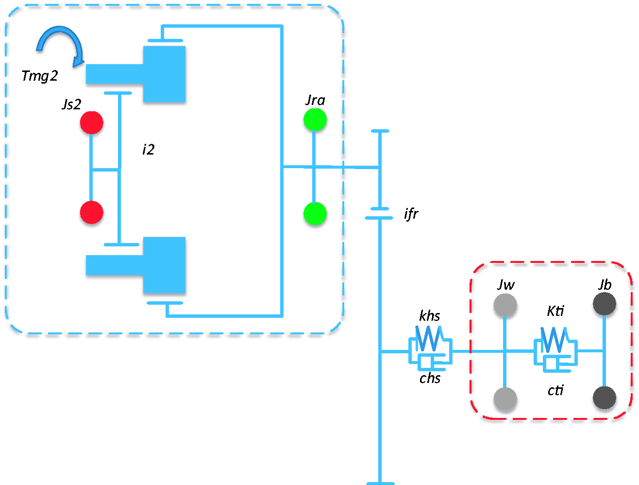
Simplified model.
The kinetic equations are as follows


The half shaft and the wheel
The half shaft can be considered as torsion spring; it has stiffness and little damping. The kinetic equation of the half shaft is

To further simplify the model, 


The kinetic equation of the car body is as follows, and the simplified model is shown in Figure 5.

Active control of the driveline vibration
Generally, the transmission axle between the gear box and the reducer is short. As a result, motor MG2 can be replaced by a mass connected rigidly to the ring, like the simplification of the reducer and the differential. In the wheel system, the body is treated like a mass loaded on the wheels. The model can then be simplified into a two-mass control model as shown in Figure 6.
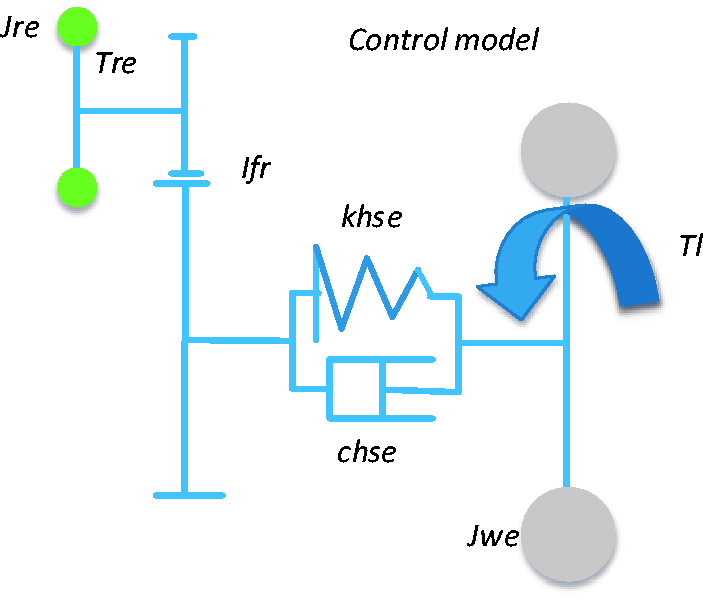
Two-mass control model.
Model analysis
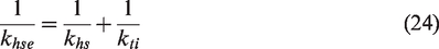
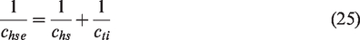
The relationship between the two-mass control model and the simplified model is


The torsional vibration differential equations of transmit in pure electric mode are then expressed as follows
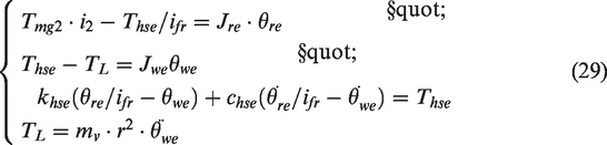
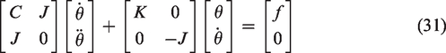
Transforming equation (29) into matrix form, gives

Where the generalized coordinate system is 
Equation (29) can be transformed as
Use
Equation (30) is transformed to
It can be calculated as

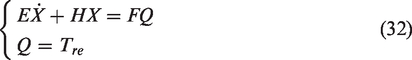
The standard form of the system state-space equation is
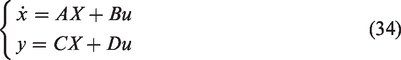
Using Laplace transformation to transform equation (34), the function matrix of the system gives

The transfer function from the angular velocity of the equivalent ring to the output torque of the ring, 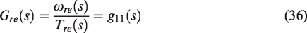
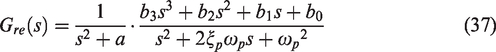

The bode chart of
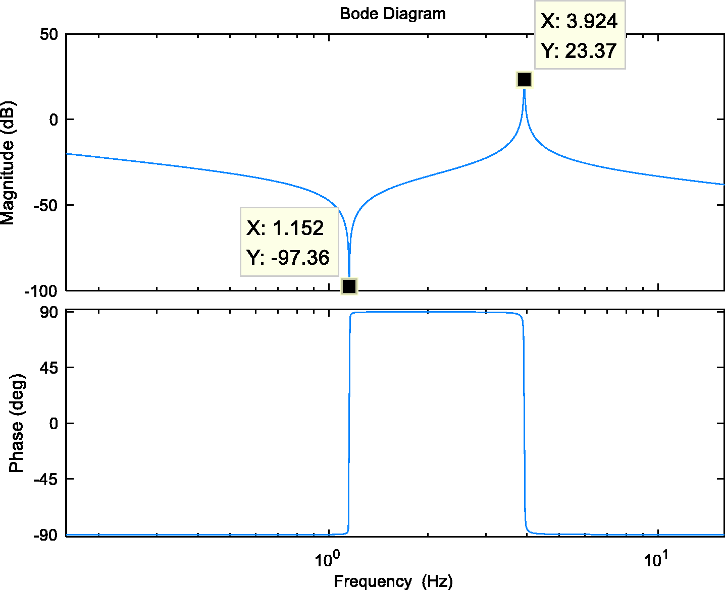
Magnitude and phase spectrum of
We can see the frequency response characteristics of
The motor can reach the needed torque within little time. As a result, a torque step signal is used to describe the torque change when the motor is working. 0.2 s after the vehicle receives the signal, the ring produces a step torque of
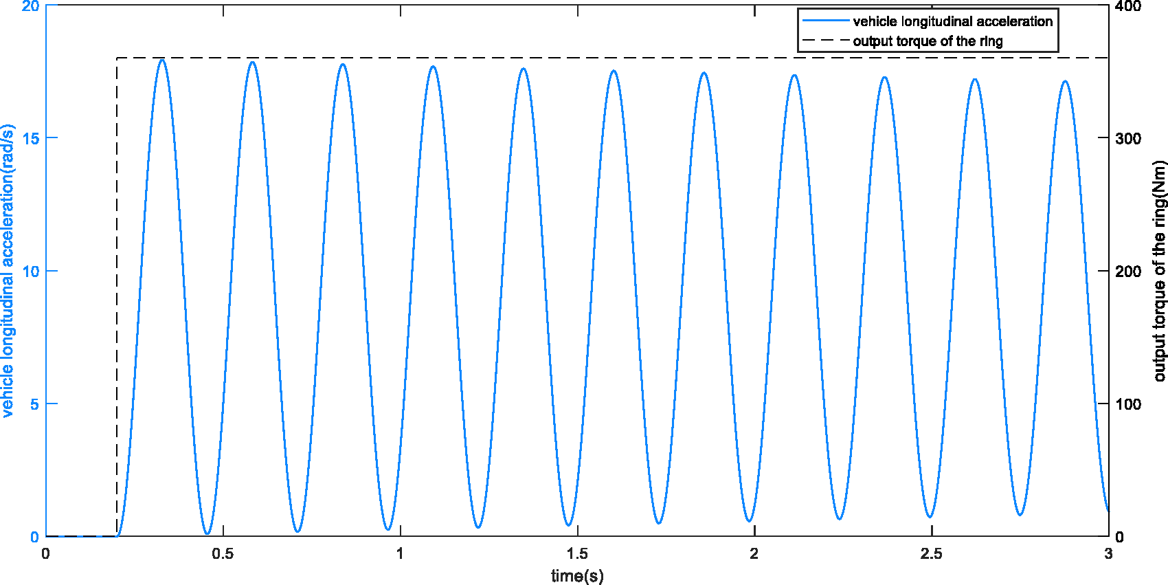
Calculated vehicle longitudinal acceleration.
In Figure 8, we can see the vehicle longitudinal acceleration has an underdamping characteristic, the magnitude of which oscillates around a certain value and attenuates slowly. This saturation makes passengers’ feeling worse.
Controller design
To control this kind of torsional vibration, compared with feed-forward control and PP, WSCS has the best effect. 12 The concept of WSCS is to delay part of the input to superimpose with the original input to eliminate the output wave. The control strategy is as shown in Figure 9. In this control model, the peak-to-peak wheel angular acceleration (WAAmax) is chosen as the index to reflect the vibration suppression effect.
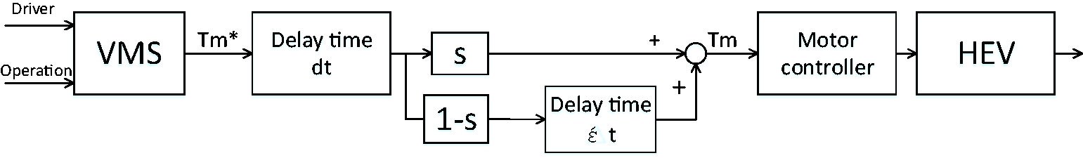
WSCS control strategy. HEV: hybrid electric vehicle; VMS: vehicle management system.
As shown in Figure 10, line 2 is used to replace line 1, the step signal of the motor torque output, which can make the torque increase smoothly to avoid large wheel angle acceleration at vehicle launch. In addition, in order to take advantage of the principle “amplitude cancellation when different phase waveform superimposed” in WSCS control, part of the torque is delayed, so line 2 is divided into line 3 and line 4. The parameters include the start time
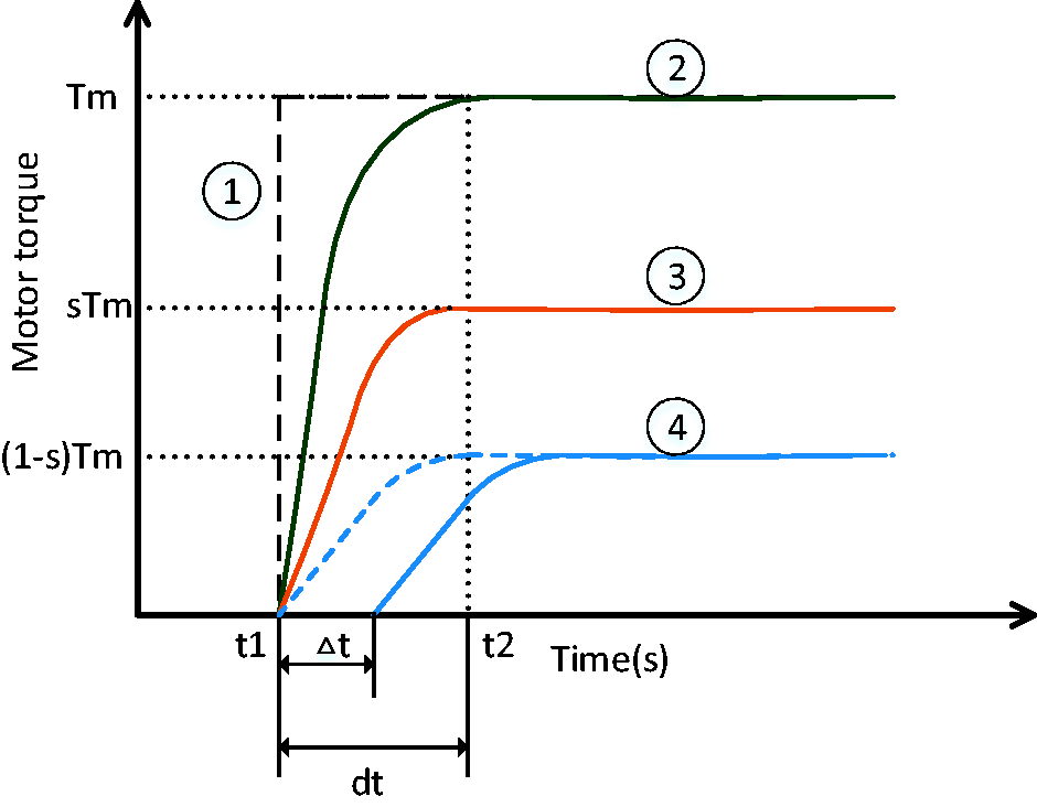
Output motor torque using WSCS.
To find the best parameters of the control strategy,
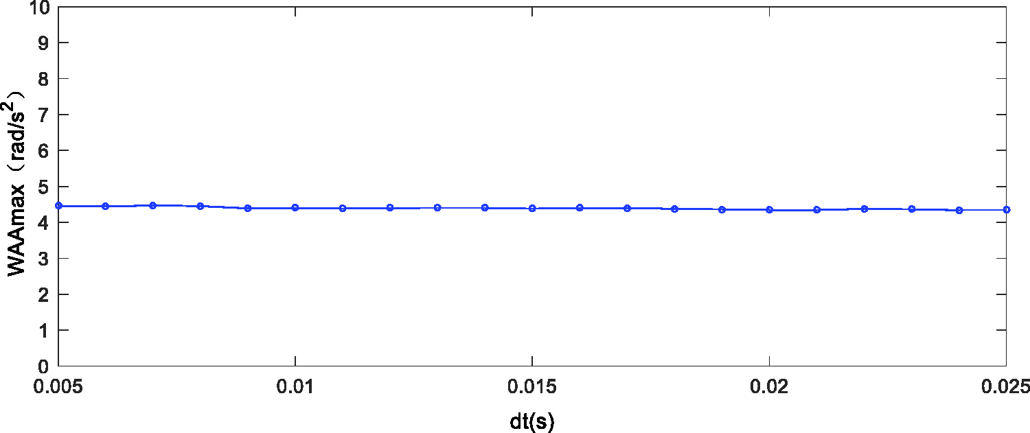
WAAmax with one variable
As shown in Figure 12, the final parameters of motor torque after improvement are
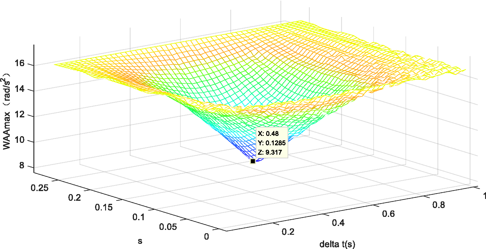
WAAmax with two variables Δt and s.
Control effectiveness
Taking the optimized parameters into the Ravigneaux planetary power-split system, the output torque of motor MG2 and the peak-to-peak vehicle longitudinal acceleration before and after control can be calculated. As shown in Figure 13, after control the output torque of motor MG2 is divided into two saturations. In Figure 14, there exists an obvious decrease in peak-to-peak vehicle longitudinal acceleration from 5.5 to
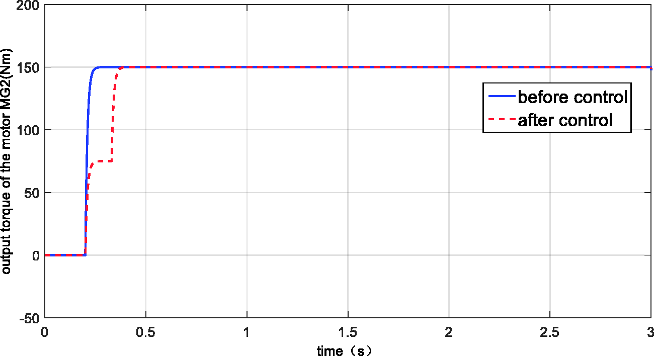
The output torque of the motor MG2 before and after control.
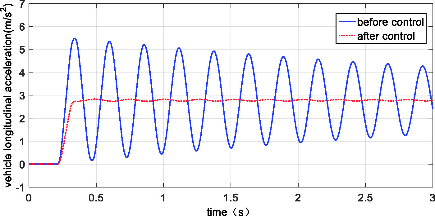
Comparison of vehicle longitudinal acceleration before and after control.
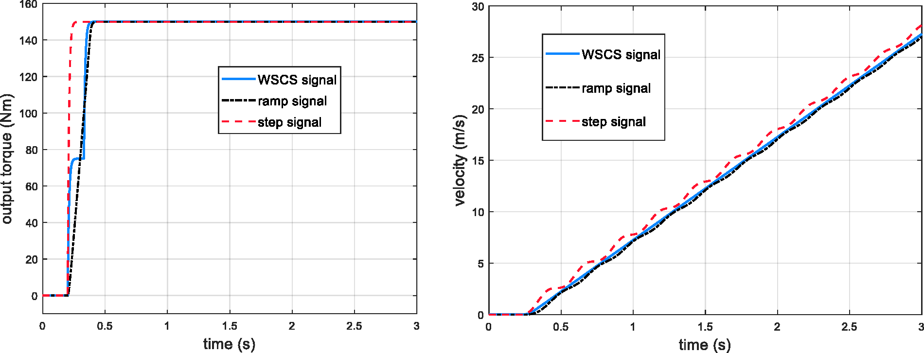
Comparison of vehicle velocity with different input torque signal. WSCS: wave superposition control strategy.
Conclusion
Unsmooth motor starting in the launch condition in HEVs causes ride discomfort. This article investigates a control strategy, WSCS, to minimize the driveline vibrations. Correspondingly, a simplified model of the Ravigneaux planetary power-split hybrid transmit system is established after simplification of many components. The concept of WSCS delays part of the input to superimpose with the original input to eliminate the output wave. During the controller design, the best parameters are found after analyzing the control model. The simulation results reveal that WSCS effectively minimizes the launch vibration, since the peak-to-peak acceleration of the vehicle is decreased by about 49.1% from the original. Furthermore, compared with the curve without control, the oscillation of the magnitude of the vehicle longitudinal acceleration essentially disappears after control. Therefore, WSCS can be considered as an ideal active control method to be further applied in HEVs to lessen the driveline vibration when HEVs start.
Footnotes
Declaration of conflicting interests
The author(s) declared no potential conflicts of interest with respect to the research, authorship, and/or publication of this article.
Funding
The author(s) received no financial support for the research, authorship, and/or publication of this article.