
Abstract
Vibrational power flow contains two types of information, namely, vibration velocity and structural internal force, and is an important parameter for measuring vibration level and transmission. Structures are often under stress because of the working environment. This stress changes the vibration velocity and internal force of the structure. As a result, this stress affects the power flow. In practical engineering, structural stress often has a complex distribution. However, earlier studies mainly focused on the overall uniformly distributed stress, which cannot be applied to practical engineering vibration problems. The finite element method can handle this problem, but has several shortcomings, such as the lack of a clear explanation of the essential relationship between structural stress and vibration, the complicated process of applying specific stress, and the large number of calculations. This study considers the effect of general structural stress and determines the dynamic equation of a structure undergoing stress. By utilizing the orthogonality of specific order modes to decouple, we obtain the power flow analytical solution, which can be applied to structures with arbitrary distributed stress. Finally, we calculate and analyze the effect of structural stress on a welding plate. Results show that structural stress has a more significant effect on power flow than velocity and inner force and should be taken into account when considering vibration prediction and reduction in practical engineering.
Introduction
Power flow is an important parameter for measuring vibration level and transmission and contains information on structural internal force and vibration velocity. Although vibration velocity and structural internal force are strongly related to vibration energy, power flow includes these types of information. As a result, power flow can reflect the essence of vibration better, from the viewpoint of energy, 1 making it an important parameter for predicting and controlling vibration.
However, the complex and special working environment implies there is stress already in the engineering structure before undertaking the workloads. The type of stresses includes but is not limited to, the welding residual stresses, manufacturing defects, submarine shell stress caused by hydrostatic pressure. These stresses can change the dynamic properties of structures, including power flow. For convenience, we refer to this kind of stress as “generalized structural stress.”
Vibration prediction and control has always been a popular field of research.2–4 The influence of generalized structural stress on vibration is important in structural design. Several researchers have investigated the initial stress effect on plate structural dynamics. Herrann and Armenakas 5 applied the variational principle to analyze the vibration and stability of an initial stress plate. Doong 6 applied high-order shear deformation theory to derive the initial stress thick-plate vibration control equation and compared their work to the findings of Brunelle and Robertson. 7 Gao and Liu performed an experimental comparison of plates with and without initial stress. 8 Other researchers investigated the initial stress effect on shell vibration. Zeinoddini and Harding 9 analyzed the effect of in-pipe fluid on tube dynamics by regarding fluid pressure as a uniform static load. Liu assessed the effect of hydrostatic pressure fields on the dispersion characteristics and power flow of cylindrical shells.10,11 Using two-dimensional high-order shear theory, Matsunage 12 analyzed the free vibration of a simply supported cylinder under axial stress. Chen et al. 13 applied a variational method to derive the dynamic equation of a cylindrical shell under local stress. Zhang utilized the wave propagation method to analyze submerged and fluid-filled cylinder free vibration characteristics.14,15 Koroma et al. 16 investigated the influence of preload of rail pads on railway track vibrations.
However, these efforts focused on uniformly distributed stress. Few studies have addressed complex distributed stress, whose values change as location varies, and even fewer studies have addressed the effect of complex distributed stress on power flow. These previous theoretical works cannot be applied to practical engineering vibration problems. The finite element method (FEM) can be used in the dynamic calculation of a structure with complex distributed stress, 17 but cannot help us understand the characteristics and laws of the effects caused by structural stress or the essential relationship between structural stress and vibration. Applying FEM to this problem is also complicated because it requires a complex stress application technique, multitudinous degrees of freedom (DOFs), and vast modeling costs, particularly for large-scale structures. Therefore, investigating the effects of general structural stress through theoretical analysis is necessary.
This study considers the effect of general structural stress and determines the dynamic equation of a structure undergoing general stress. By utilizing the orthogonality of specific order modes to decouple, we obtain an analytical solution that can be applied to a structure with arbitrary distributed stress and can overcome several of the shortcomings of FEM. In the numerical examples, we calculate and analyze the effects of structural stress in a welding plate. Results show that structural stress has a more significant effect on power flow than velocity and inner force and should be considered in practical engineering problems of vibration prediction and reduction.
Theory
Dynamic equation of plate with general structural stress
In this study, we derive the dynamic equation of a plate with general structural stress. The plate is shown in Figure 1. The plate is simply supported, with length L, width B, thickness h, and structural stress, including tensile stresses (
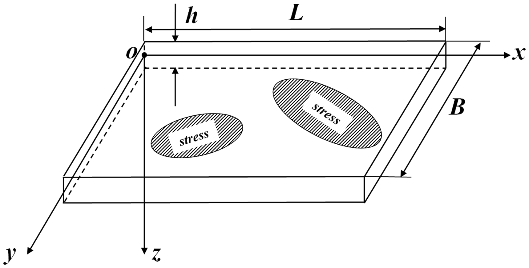
Plate model with complex distributed stress.
Before derivation, the following assumptions are made:
Structural stresses and stresses caused by vibration satisfy the linear superposition. The vibration satisfies the small elastic deformation condition. The stress is uniformly distributed in the direction of thickness. Stress relief is not considered in this study.
In an element body from the plate, length and width directions are dx and dy, respectively. The force diagram of an element with structural stress from a static plate is shown in Figure 2.
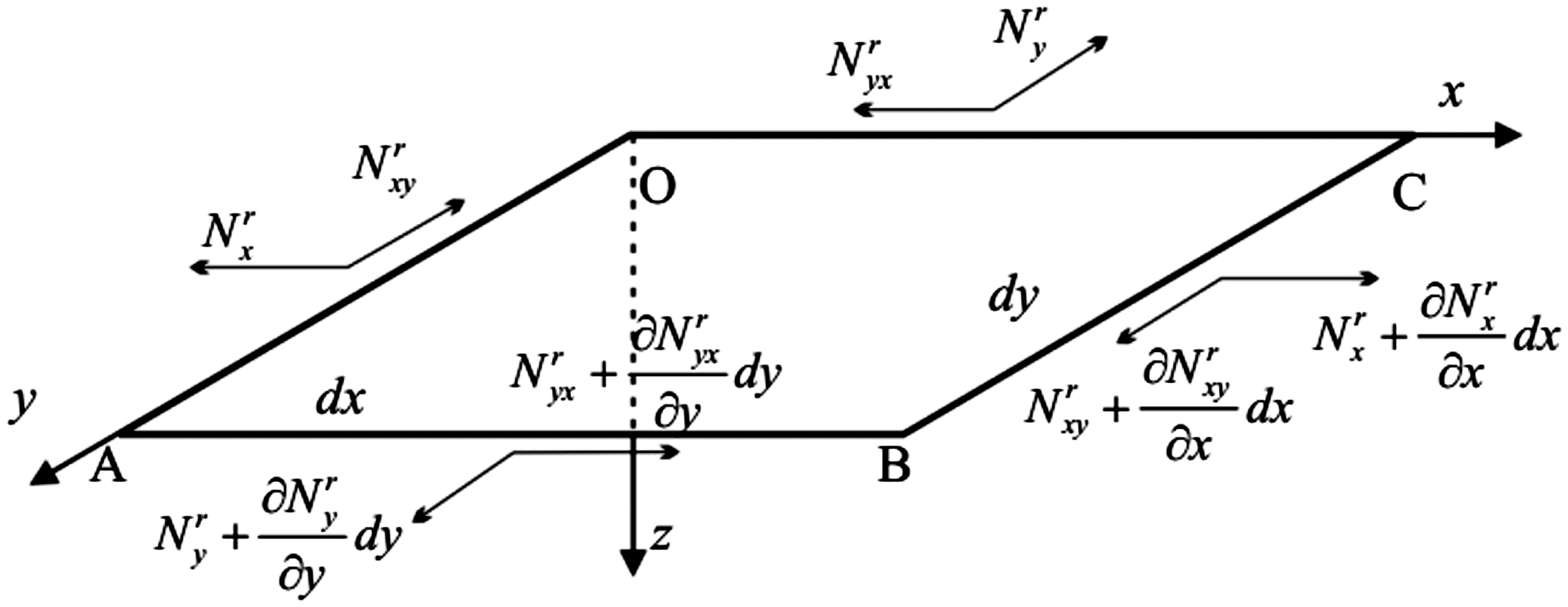
Element body force diagram.
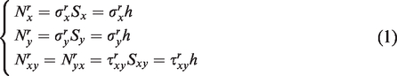
In Figure 2,
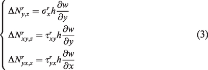
When the plate is vibrating, the forces and moments of the element body may be divided into two parts: Part 1 is the force and moment caused by vibration deformation and Part 2 is the coupling force and moment caused by vibration deformation and structural stress. Part 1 can be expressed by classic plate theory, 18 as follows:
When the plate is vibrating,
By the same derivation, we obtain the other new components, which can be expressed as follows
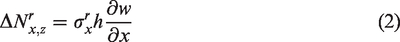
Based on Kirchhoff thin-plate theory, in which the stress value remains unchanged in the thickness direction, we do not need to consider the coupling moments and torques. The derivation shows that structural stress and vibration displacement produce new coupling forces in the z-direction, and these forces affect the equilibrium equation and change the structural dynamic equation. Furthermore, no new coupling forces are generated in the x- and y-directions, such that the force equilibrium equations in the x- and y-directions are still satisfied. Only the new force equilibrium equation in the z-direction and the moment equilibrium equations should be built.
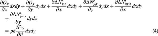
New force equilibrium equation in the z-direction
In stressed structures, the new coupling forces (2) Moment equilibrium equations
New coupling moments are not considered in this study. Based on Kirchhoff thin-plate theory, the moment equilibrium equations in the x- and y-directions are expressed as follows


Substitution of equations (5) and (6) into equation (4) yields the following expression
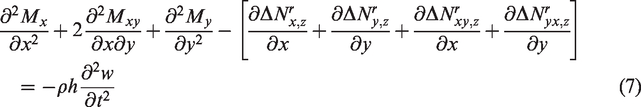
Substituting equations (2) and (3) into equation (7) yields the stressed plate vibration equation

Solution of the equation
The boundary condition is assumed to be simply supported, and the displacement can be expressed in the following series
18
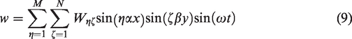
By substituting equation (9) into equation (8) and multiplying both sides of equation (8) by
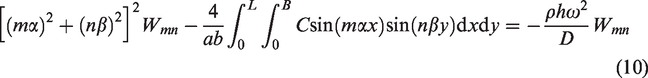
The C integration term in equation (10) is expressed as K for simplicity,
This study considers the normal stress only. If the stress value varies in one direction, then one-dimensional structural stress can be expressed as follows
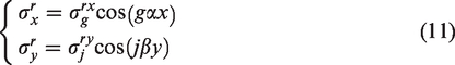
Substituting equation (11) into K yields the following expression
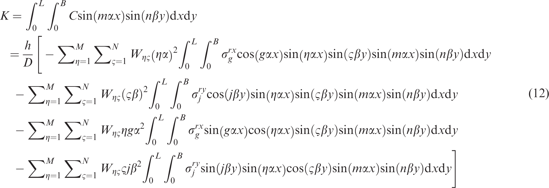
According to the product to sum formula
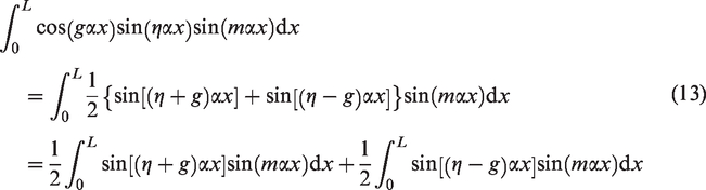
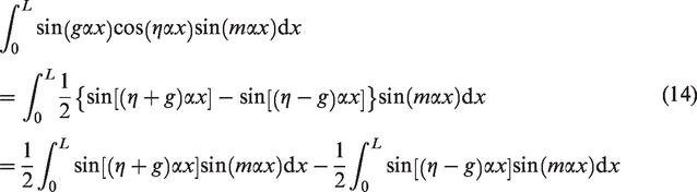
According to the orthogonality of the trigonometric function, we derive the following expressions
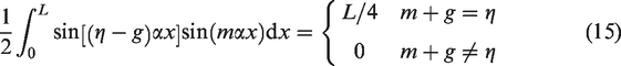
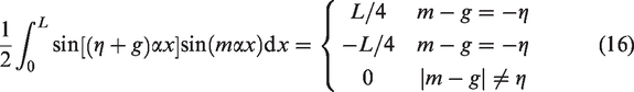
Using equations (13) to (16), the first and third terms can be simplified into the following expressions
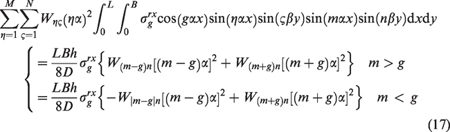
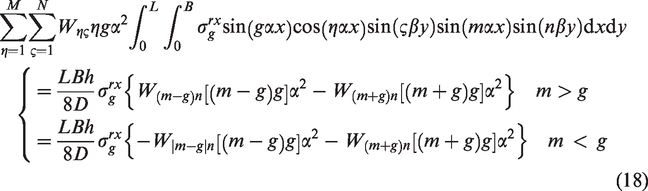
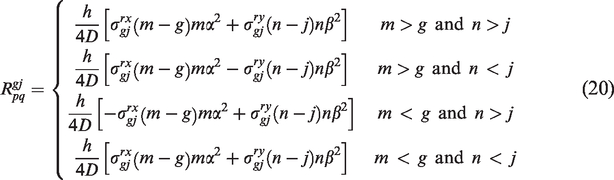
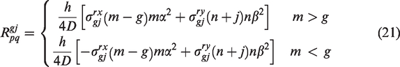
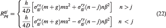
Equations (17) and (18) show that coupling occurred among specified modes only. Each mode is coupled with several specific modes, rather than all other modes. The second and fourth terms can be simplified in the same manner. Therefore, for the final vibration equation, terms that correspond with specific coupling modes must be computed. Then, we can express the resultant


When the stress distribution is more complex, stress can be expressed in series as follows
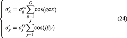

If the stress value varies in two directions, then the two-dimensional structural stress can be expressed as follows
Most distributions can be expressed in the trigonometric form in equation (24) or (27). Thus, the presented method is applicable to the dynamic calculations of practical engineering structures.
The determinant of the coefficient matrix in equation (25) needs to be zero
18
to solve the free vibration of a structure under structural stress, as follows

We can obtain the natural frequency and mode shape of the general structural stress by solving equation (28).
If a vertical distributed force, fz, exists, then the forced vibration equation of a general stressed plate can be expressed as follows

The vertical distributed force, fz, can be expressed as the same series as the displacement expression in equation (9), as follows
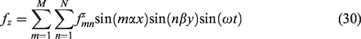
Substituting equations (9) and (30) into equation (29), we can derive the forced vibration matrix equation of a plate under general structural stress as follows

We obtain the displacement coefficient
Power flow equation of structure with stress
Power flow theory
In practical vibrating structures, we often use the time-averaged power flow to measure the vibration level, which can be expressed as follows
19


Based on Kirchhoff’s thin-plate theory, equations (28) and (29) can be simplified into the following expressions


The total power flow is
Solution of complex stress structure power flow
As shown in equations (30) and (31), we need the values of the shear forces, moments, linear velocity, and angular velocity to obtain the power flow. These values can be obtained by differentiating the displacement expression.
20
Substituting the displacement field derived in the section Solution of the equation into the calculation formulas of these parameters, we obtain the following expression
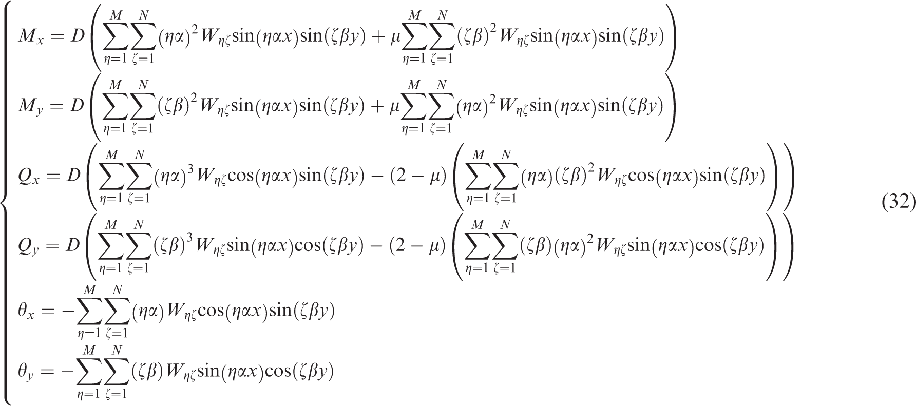
Then, substituting equation (32) into equations (30) and (31), we obtain the power flow of a plate with structural stress.
Numerical examples
Verification of the method validity
In this study, we verify the validity of the proposed method by a numerical example. The plate model is simply supported, as shown in Figure 3, and the color represents structural stress. The parameters of the model are length L = 1 m; width B = 1 m; thickness h = 0.01 m; density
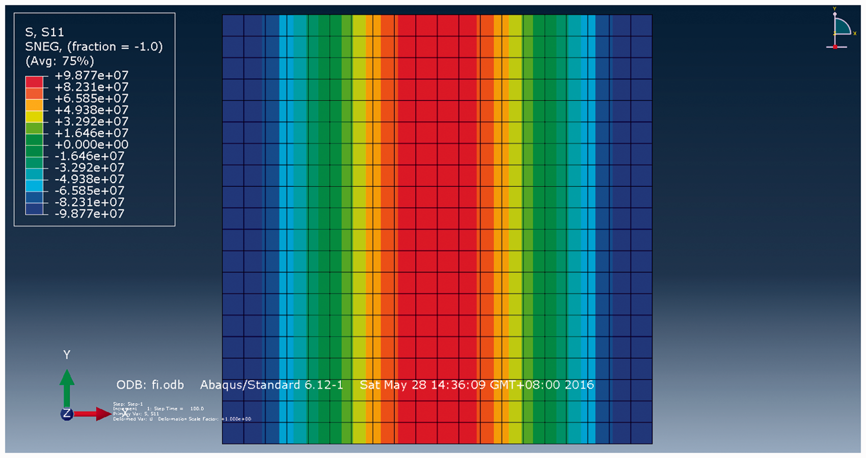
Structural stress distribution of FEM plate model in Abaqus.
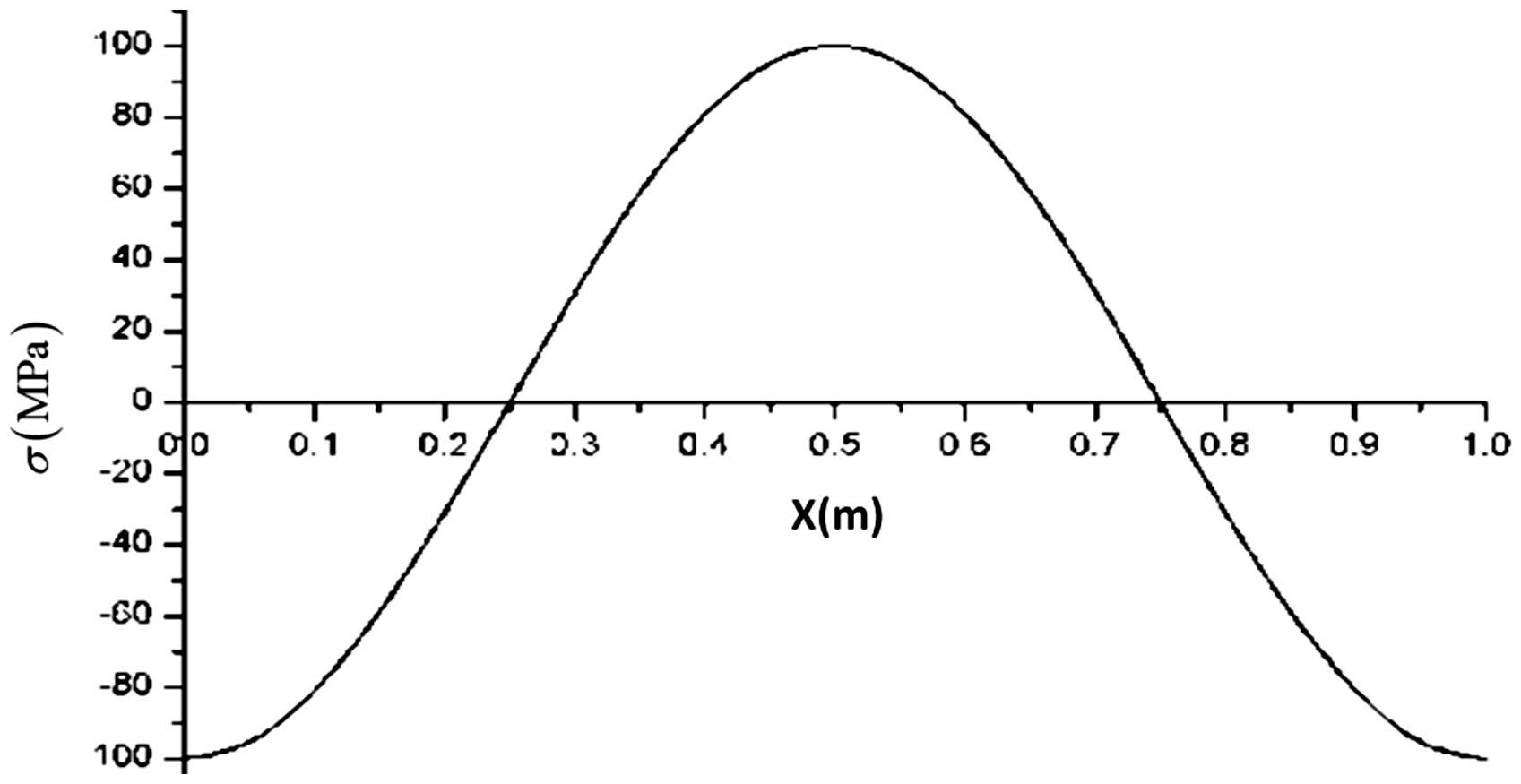
Structural stress distribution in the verification case.
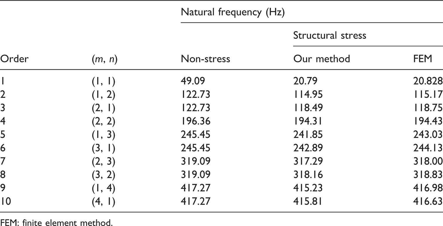
Comparison of natural frequency.
FEM: finite element method.
Table 1 shows that the differences between results obtained from our method and FEM do not exceed 0.6%. The largest difference is 0.51%, occurring in the sixth mode, in which our method obtains a natural frequency of 242.89 Hz, whereas the FEM result is 244.13 Hz. The smallest difference is 0.06%, occurring in the fourth mode, in which our method obtains a natural frequency of 194.31 Hz, whereas the FEM result is 194.43 Hz. The natural frequency comparison verifies the validity of our method. In this example, the most significant influence happened in the first order natural frequency, but it should be pointed out that this phenomenon is not a specific rule. In some other examples, the most significant influence may happen in other frequencies. The influence of the stress on the natural frequency depends on the plate properties and the stress distribution.
At the same time, although pure computation time does not exhibit a significant difference between FEM and the presented method, FEM requires more complicated and time-consuming operations to exert a specified stress distribution during modeling. Moreover, when the mesh is updated or stress distribution changes, these complicated operations must be rerun. If the stress distribution changes frequently or the structure is large with numerous elements, then FEM modeling would be time-consuming. Our method is more appropriate for analyzing the characteristics and effect rules and for clarifying the essential relationship between structural stress and vibration.
Effects of structural stress on power flow
In this study, we calculate the influence of practical structural stress on vibrational power flow. A certain type of welding residual stress is used as the structural stress in the numerical example. A welding plate example from Liu
21
is investigated in this analysis, with basic parameters of length L = 2 m; width B = 2 m; thickness h = 0.02 m; and the welding line is located at x = 1 m; the other structural parameters are the same as that in the previous section. The plate is simply supported. The welding plate model is shown in Figure 5, and the welding stress distribution is shown in Figure 6. We consider only x-directional stress and assume that the stress value remains constant in the y-direction for simplicity. The force amplitude is
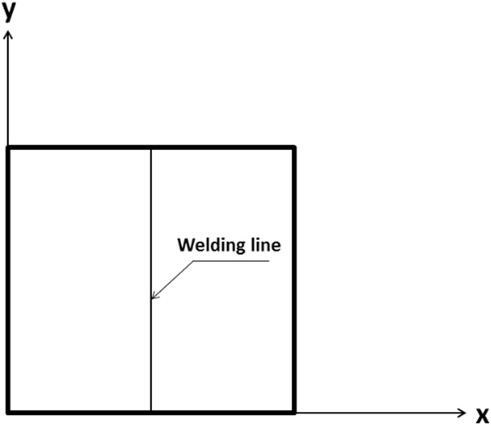
Welding plate with complex distributed residual stress.
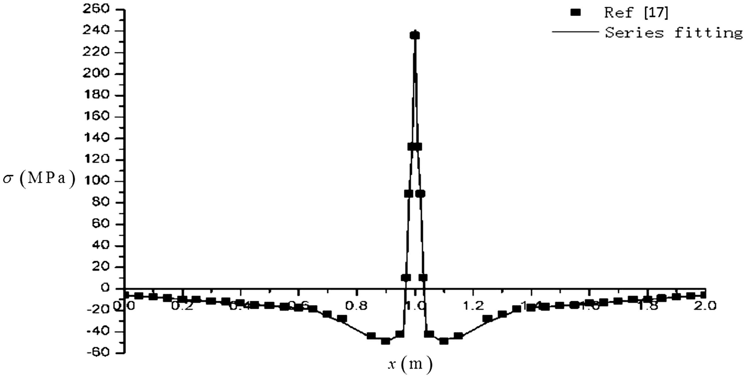
Plate welding residual stress distribution.
We calculated and compared the dynamic parameters of a non-stressed plate and the structural stressed plate. The computational diagram of the stressed plate is shown as follows:
Fit the stress distribution by the trigonometric function series equation (27), and obtain the coefficient Substitute the stress expressions into equation (29), and obtain the coefficient After obtaining Substitute equation (32) into equations (30) and (31), then we can obtain the power flow of a plate with structural stress.
The computation results are shown in Figures 7 to 14. In these figures, subfigure (a) represents the non-stressed plate results, subfigure (b) represents the structural stressed plate results, and subfigure (c) represents the difference between subfigure (a) and subfigure (b).
From the result comparisons above, we can find: Figures 7 to 9 show that the influence of structural stress on velocity is nonsignificant. The most difference in Figures 7 to 9 are 1.05%, 2.65% and 2.53%, respectively. Compared to the velocity parameters, Figures 10 to 13 show that the influence of structural stress on the force parameters is clearer and stronger. The most difference in
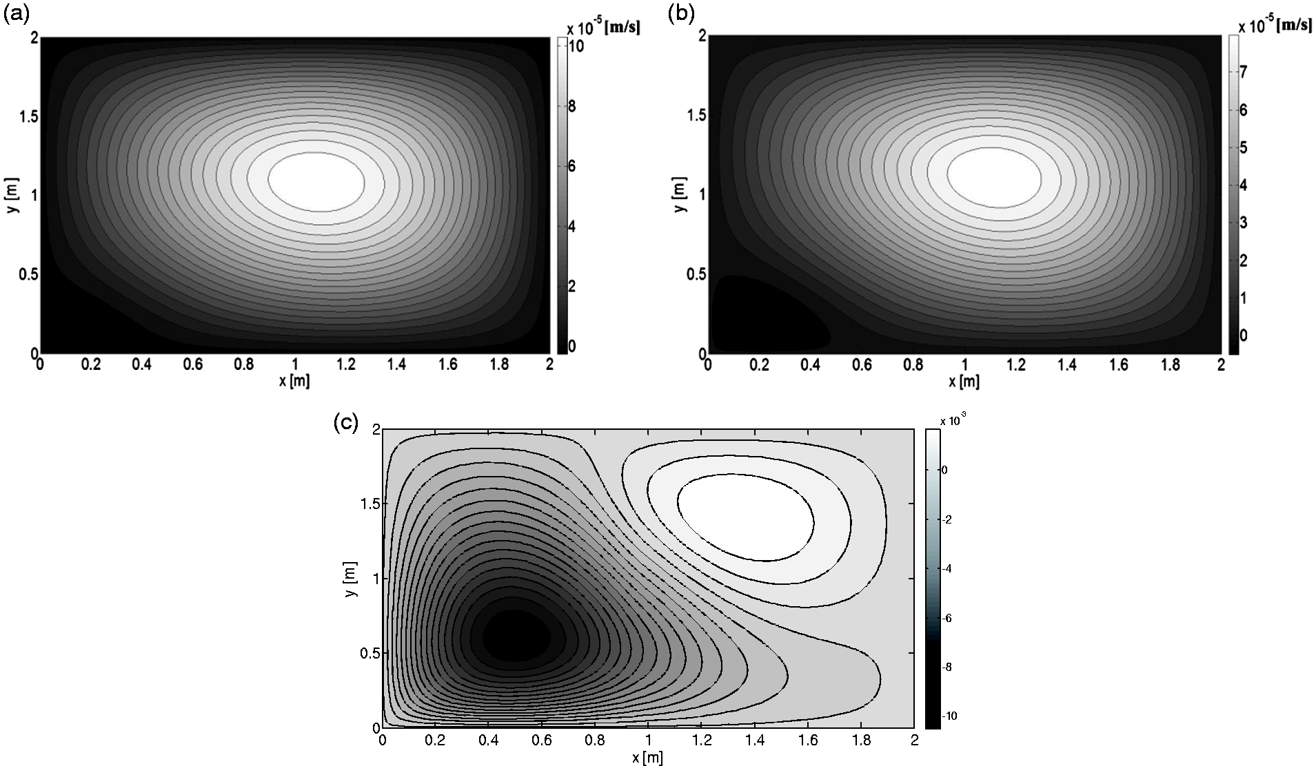
Comparison of the linear velocity of (a) non-stressed, (b) stressed plates and (c) difference.
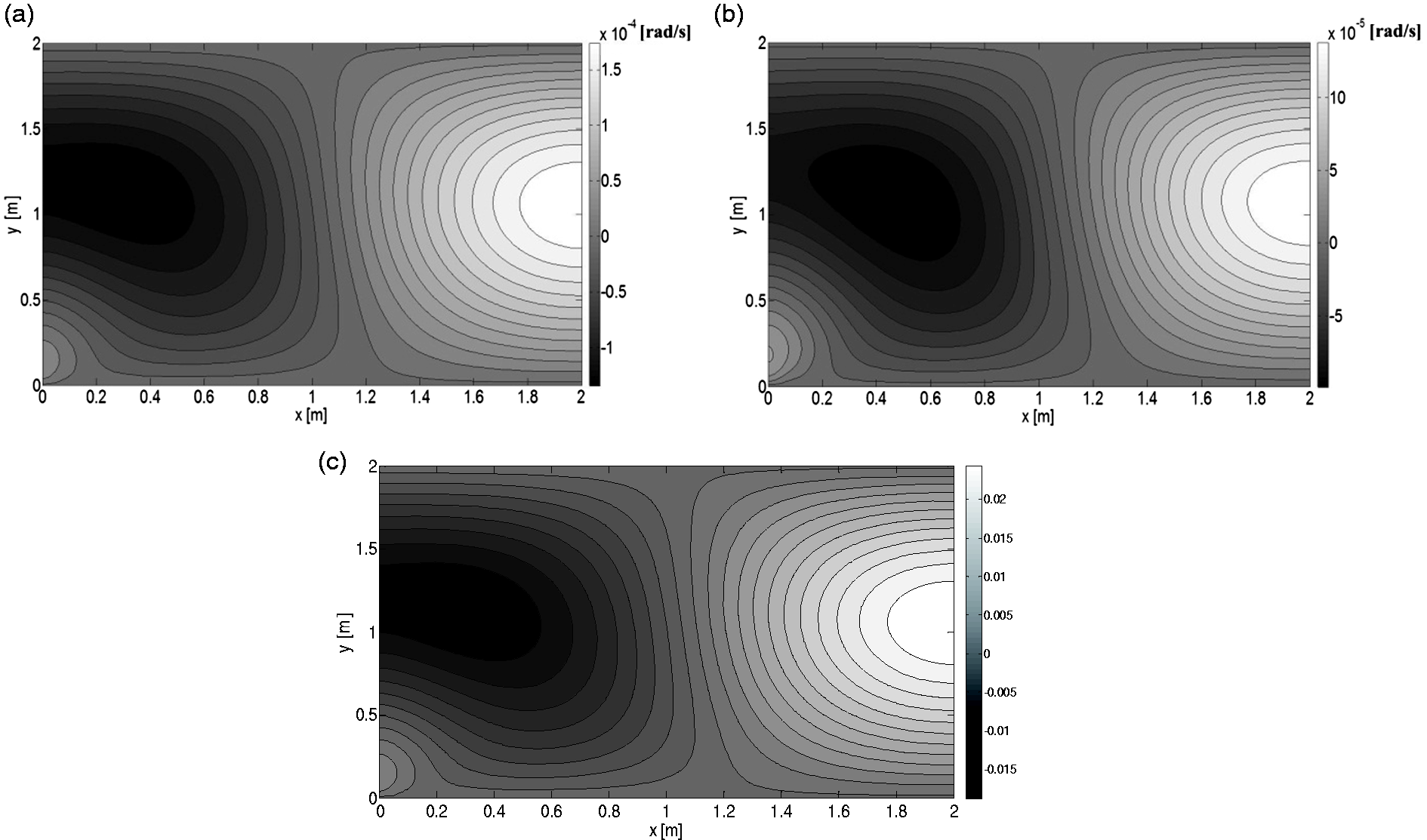
Comparison of angular velocity
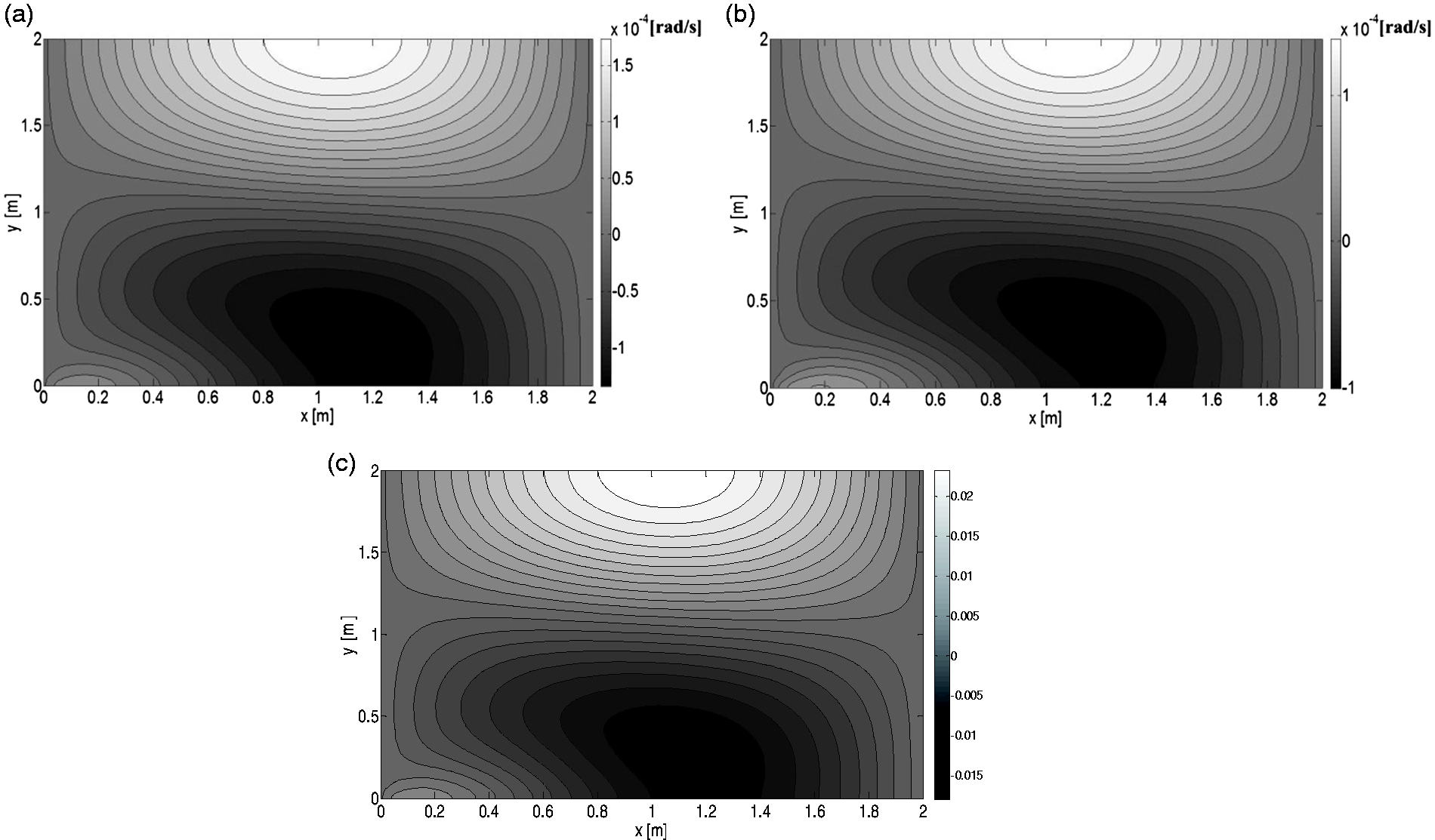
Comparison of angular velocity
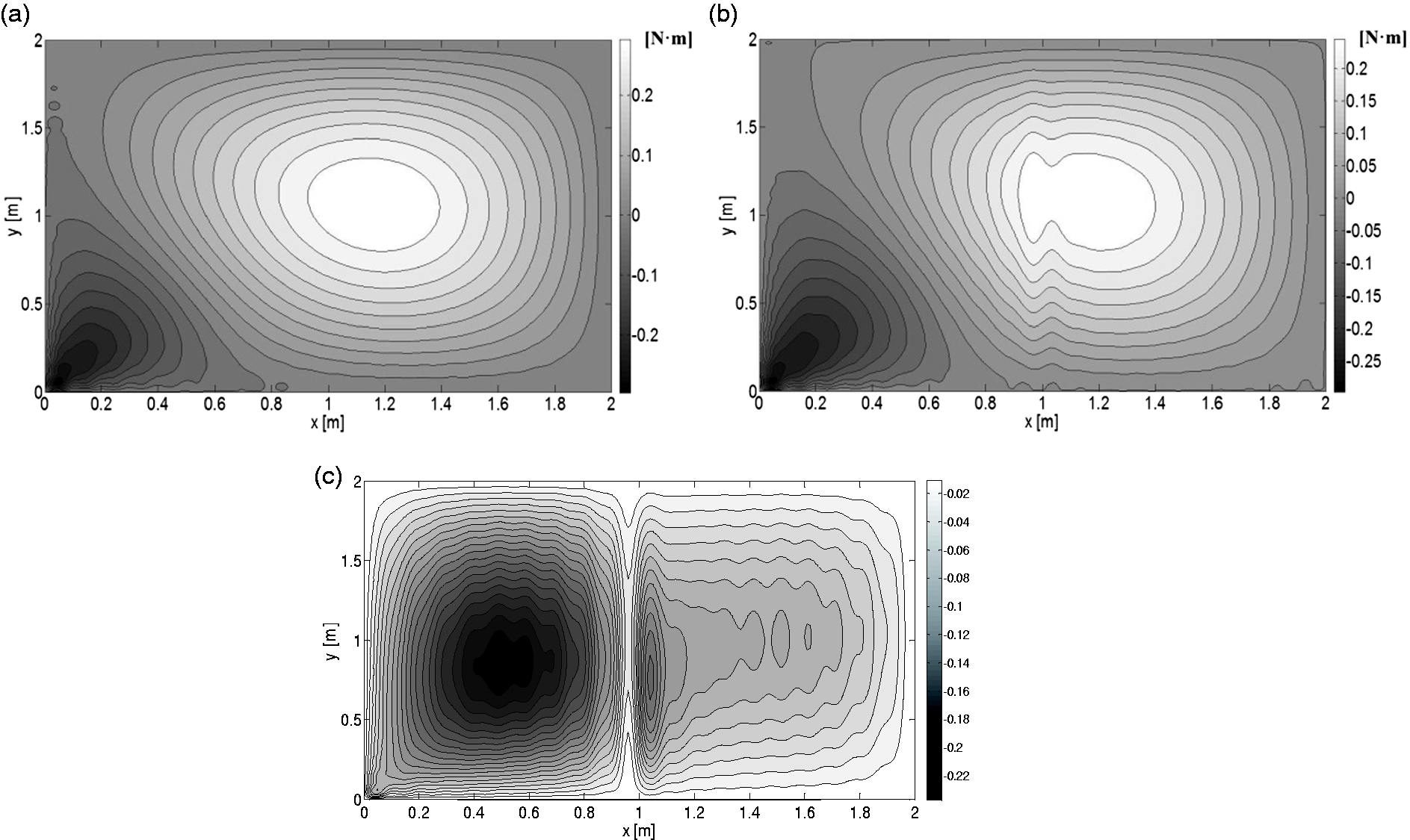
Comparison of moment
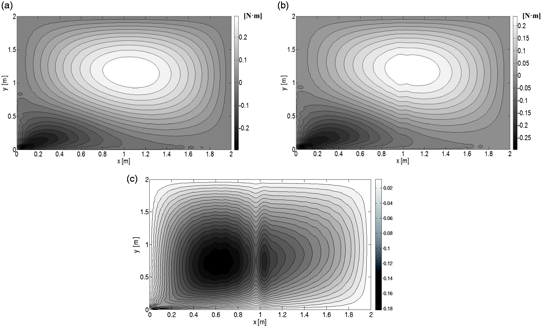
Comparison of moment
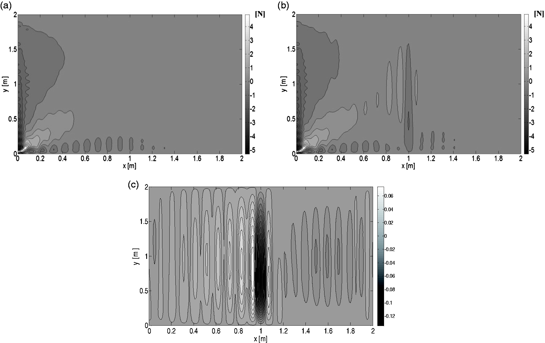
Comparison of shear force
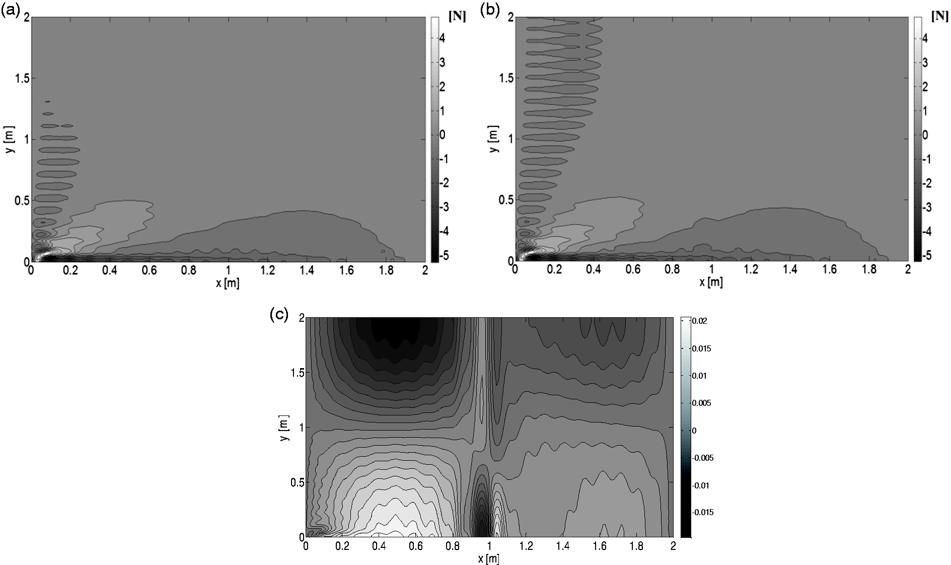
Comparison of shear force
Comparing the results shown in Figures 7 to 13 with those shown in Figure 14, the influence of structural stress on power flow is more significant than velocity or force parameters, and the most difference value in the power flow is 111.6%. We need to reprocess the velocity and force parameters to obtain power flow (as shown in equations 30 and 31). Thus, during reprocessing, the structural stress influence on the force parameters and velocity parameters would be superposed and magnified and would reflect the power flow difference between non-stressed and stressed structures. Especially in the stress distribution area, the force and velocity parameters changed more dramatically which leads a greater power flow change than the non-stress area, so it is the reason for the result that there is a clear discontinuity in the stress area. Therefore, the structural stress has the most significant influence on power flow. In addition, the figure of stressed plate power flow shows an evident discontinuity at the stress location x = 1 m, indicating that power flow analysis has aspects of stress detection or damage location.
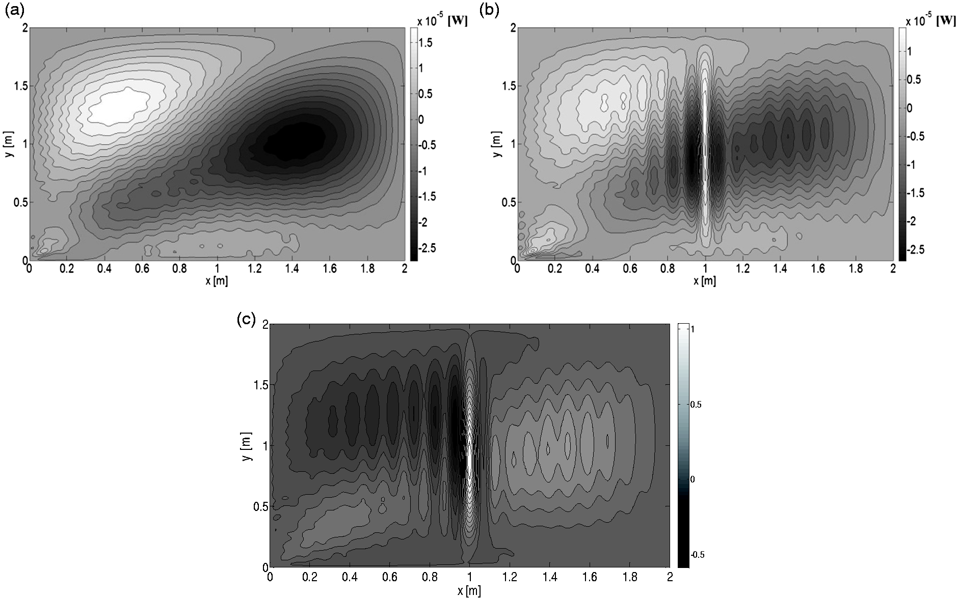
Comparison of power flow I of (a) non-stressed, (b) stressed plates and (c) difference.
Conclusion
Power flow is an important parameter for measuring and controlling vibration. In practical engineering structures, stress often exists, which can change power flow. However, the distributions of these stresses are always complex rather than uniform. Earlier studies and FEM analyses have shortcomings when solving this problem. In this study, we investigated the influence of general structural stress on power flow using a theoretical method. Based on Kirchhoff plate theory, we used the orthogonality of specific order modes to derive the power flow equation of the structural stress plate. Then, we calculated and compared the influence of complex stress on vibration velocity, structural internal force, and power flow.
Results show that our method is more appropriate for analyzing the characteristics and general rules of the effects and for clarifying the essential relationship between stress and vibration. The process of obtaining power flow magnifies the influence of structural stress on vibration velocity and structural internal force. Thus, power flow is more affected.
At present, the proposed method has the following limitations: The method can only be applied to several simple structures, such as plates and shells. If the boundary condition is not simply supported, then the simplification in this paper is unusable and has a large computation cost. The series also needs to be developed for quick convergence. In future research, these problems must be investigated further. Analyzing the influence of practical structural stress to assist forecasting and to reduce vibration and noise is also necessary.
Footnotes
Declaration of conflicting interests
The author(s) declared no potential conflicts of interest with respect to the research, authorship, and/or publication of this article.
Funding
The author(s) disclosed receipt of the following financial support for the research, authorship and/or publication of this article: The work presented in this paper was supported by the Fund of State Key Laboratory of Ocean engineering (grant no. 1507) and also was sponsored by Shanghai Sailing Program 18YF1411500.