
Abstract
The internal electro-hydraulic servo system of a hydraulic press is affected by the non-linear friction, and it becomes non-linear, unstable under vibration. In this study, the dynamic behavior and control of such a system were investigated. A mathematical model was first built and then proportional-integral-derivative control and sliding mode control were applied. Particle swarm optimization was used to find the optimal gain values and proportional-integral-derivative control parameters to control and stabilize the system. Sliding mode control was used for interactive comparison to demonstrate that the controller could avert chaos and restore stable periodic motion. A circuit was designed and assembled for the experimental confirmation of the results. The results showed that control of nonlinear behavior was better with sliding mode control than proportional-integral-derivative. This study can serve as a reference for the further investigation of hydraulic press electro-hydraulic servo systems.
Keywords
Introduction
The electro-hydraulic servo system of a hydraulic press comprised a number of mechanical parts, which together have extremely non-linear and unstable characteristics. The system relies on the reciprocal back and forth motion of the piston to build pressure and generate hydraulic power. Electro-hydraulic servo systems are widely used in automation, for hydraulic presses, flying simulation platforms, and the steering gear system in ships. The hydraulic press is the most well-known application. However, electro-hydraulic servo systems can exhibit dynamic instability should the behavior of the work medium become non-linear and a topic that needs attention is the maintenance and control of stability in the system. Controller design is the main topic of this study and two methods were investigated. Both proportional-integral-derivative (PID) control and sliding mode control (SMC) were considered. Improvements were made to reduce the non-linear behavior in these two control methods and the results were compared by experiment. Dynamic modeling of the electro-hydraulic servo system and simulation of the circuit was done and the observations were analyzed. Particle swarm optimization (PSO) was used to search for the optimal PID parameter and for the development of a suitable PID controller. A theoretical model of the SMC controller was derived and simulations were done using Matlab/Simulink. Finally, circuits were developed for both types of controller. Experiments showed that both methods can keep an electro-hydraulic servo system dynamically stable and suppress chaotic behavior.
The electro-hydraulic servo systems used in a wide range of engineering applications include many components that exhibit non-linear behavior.1–3 This means that non-linear dynamic phenomena can occur, such as chaotic motion and jumping.4–6 Many related studies make extensive use of modern theories and non-linear dynamics to explore system behavior.7,8 Wu and He 9 have made serious contribution to the analysis of nonlinear systems using the Homotopy perturbation method. There were also some other control schemes where nonlinear system control was applied.10,11 For our analysis of an electro-hydraulic servo system, we used various value analysis methods 12 such as the phase trajectory diagram, bifurcation diagram, Poincaré map, spectral analysis and the maximum Lyapunov exponent, all of which can be reliably used to analyze the stability of non-linear systems.
We used a simple hydraulic cylinder to build a servo system dynamic theory model. This was used to simulate the dynamic phenomena under different parameters, and to analyze the numerical values. The system dynamics equation allowed us to understand that when an exciting force enters the system at a fixed frequency, the introduction of non-linear friction and spring force will produce non-linear dynamics, piston displacement, and speed instability.
The electro-hydraulic servo system is the main component of a hydraulic press. These presses are mainly used for stamping parts in factories, and they are more dynamically stable, have less vibration, and make less noise than their mechanical counterparts. However, advances in technology mean that hydraulic presses are now required to be more stable and precise. Careful model building and analysis can be used to assist in the design of controllers that can be used to maintain system dynamic stability and precision.
Electro-hydraulic servo systems are extremely unstable and successful control methods that have been used include fuzzy 13 and adaptive control.14,15 In this study, both methods have been used. Because the system is non-linear and unstable, it is difficult to determine the suitable values for the PID controller parameters manually. We used the widely known particle swarm algorithm (PSO) 16 to search for and determine the optimal PID controller parameters. 15 In addition, we used SMC (first used by Soviet scholars in 1950) for variable system motor control.15–17 Almost all modern variable structure control is based on the sliding mode now. In this non-linear system, a control signal causes the system to move or “slide” along the value of system normal behavior. Control methods are then used to force the system track back into the sliding surface so that it becomes stable and can be completely controlled. We explored and compared the different effects of these two control methods on the electro-hydraulic servo system. Control circuits were then realized to serve as a basis for the rapid analysis of system dynamics.
Electro-hydraulic servo system
As mentioned before, we used a common dual action single piston hydraulic cylinder as our theoretical model. Simple harmonic excitation force drives the piston back and forth in the cylinder (see Figure 1). The friction between the piston and the wall of the hydraulic cylinder can affect the system and produce non-linear and unstable dynamic phenomena. The input items are the hydraulic oil pressure, pulsation, the flow quantity and the pressure at the valve entry/exit. Hydraulic pressure at the entrance to the hydraulic cylinder will exhibit slight fluctuations which obey the laws of simple harmonic vibration.
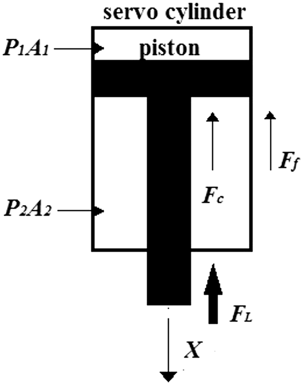
Theoretical servo hydraulic cylinder model.
There are other non-linear factors in this model, such as the hydraulic pressure spring force and damping force. However, very few studies have been made that explore the non-linear friction changes in an electro-hydraulic servo system and research on this type of non-linear system is an important focus for future studies.
Electro-hydraulic servo system dynamic equation analysis
The dynamic equation for the servo hydraulic cylinder theoretical model is as described in equation (1)


Input item on the right side of the equal sign conforms to the simple harmonic excitation law. Equation (2) can be re-written as

The structure of equation (3) shows that it can be perceived as a Duffing-Van Der Pol coupling equation with damping. To make value analysis more convenient, we can further organize the equation as

Finally, after simplification and letting
System dynamic analysis and verification
System dynamic analysis
We used three different analytical methods, the phase trajectory graph, the Poincaré map, and spectral analysis to simulate the model system dynamic phenomena. For this study, we added external excitation force
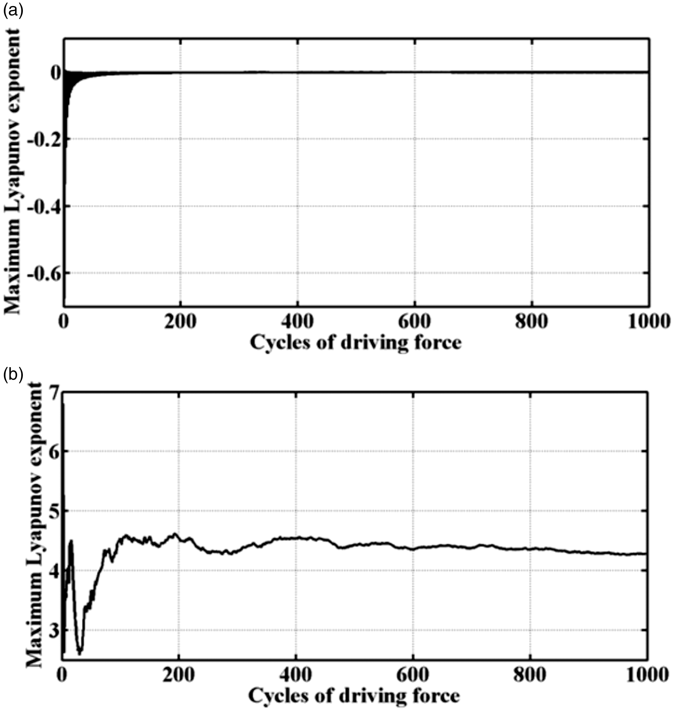
μ=0.1102, 0.0375, 0.0262, 0.0738, 0.0848, 0.0013, 0.087, 0.0949, 0.0019, 0.0263. In this study, a large number of graphs were generated, so only the dynamic analysis Poincaré map and the spectral analysis graphs of μ = 0.1102, 0.0263 are shown as illustrations.
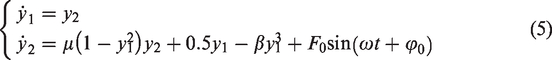
Figure 2 shows the phase trajectory graph drawn with different μ parameters. The graph shows that when the μ = 0.1102, the system exhibits 1T cyclic behavior. When μ=0.0263, the system shows disorderly and irregular non-cyclic motion.
μ value and system track (a) μ = 0.1102; (b) μ = 0.0263.
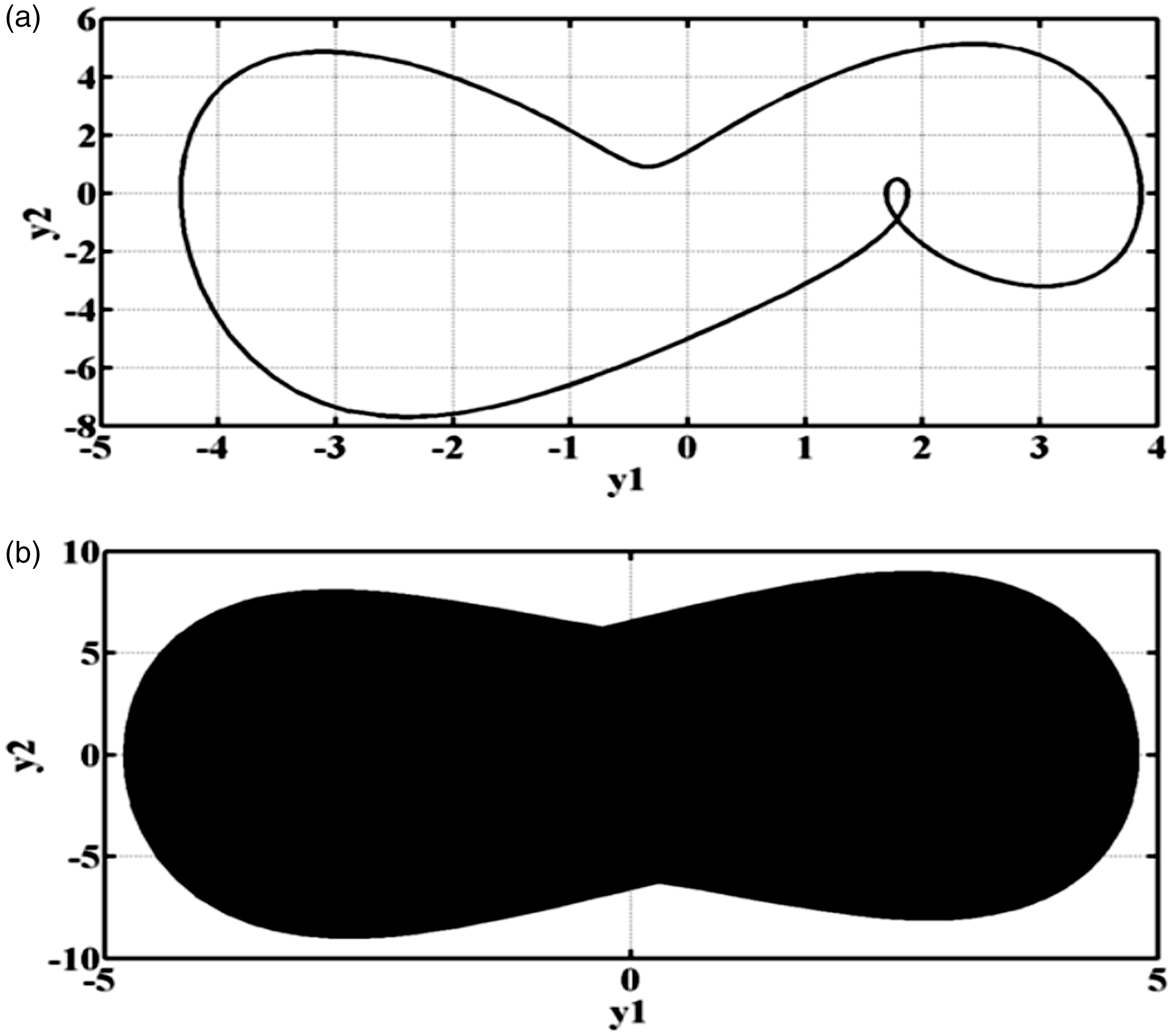
Figure 3 shows the Poincaré map of the system. When μ = 0.1102, the system exhibits single cycle motion. When the system parameter μ = 0.0263, this system exhibits disorderly and irregular non-cyclic motion.
μ value and system Poincaré map illustration (a) μ = 0.1102; (b) μ = 0.0263.
Figure 4 shows the system frequency analysis response graph. The graph shows that when μ = 0.1102, both y1 and y2 exhibit single cycle motion that is regular and stable. However, when μ = 0.0263, the system exhibits disorderly and irregular non-cyclic motion.
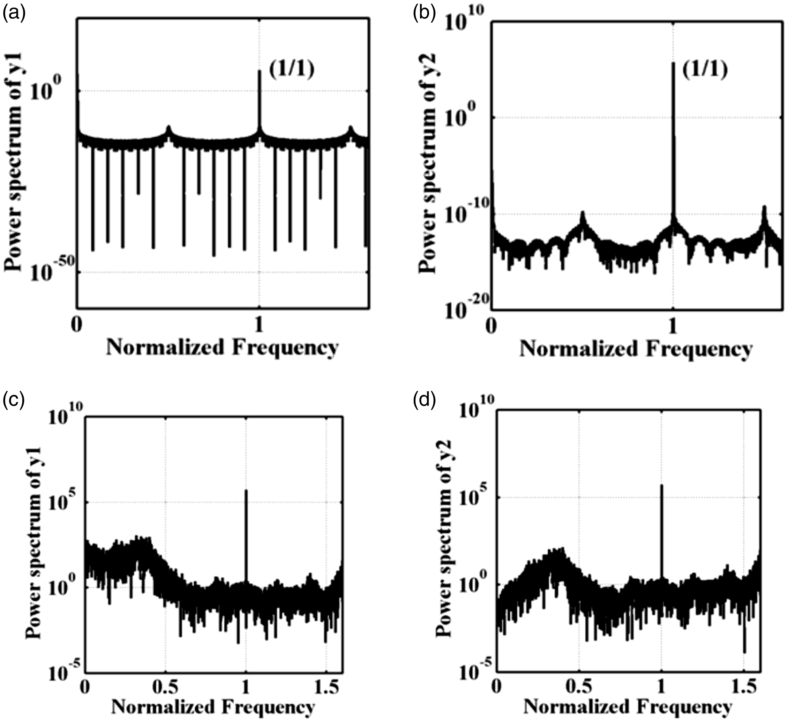
μ value and frequency domain analysis illustration (a) y1/μ = 0.1102; (b) y2/μ = 0.1102; (c) y1/μ = 0.0263; (d) y2/μ = 0.0263.
The results from the three methods used are summarized in Table 1.
Parameter μ and motion behavior.
System dynamic verification
For an in-depth exploration of “
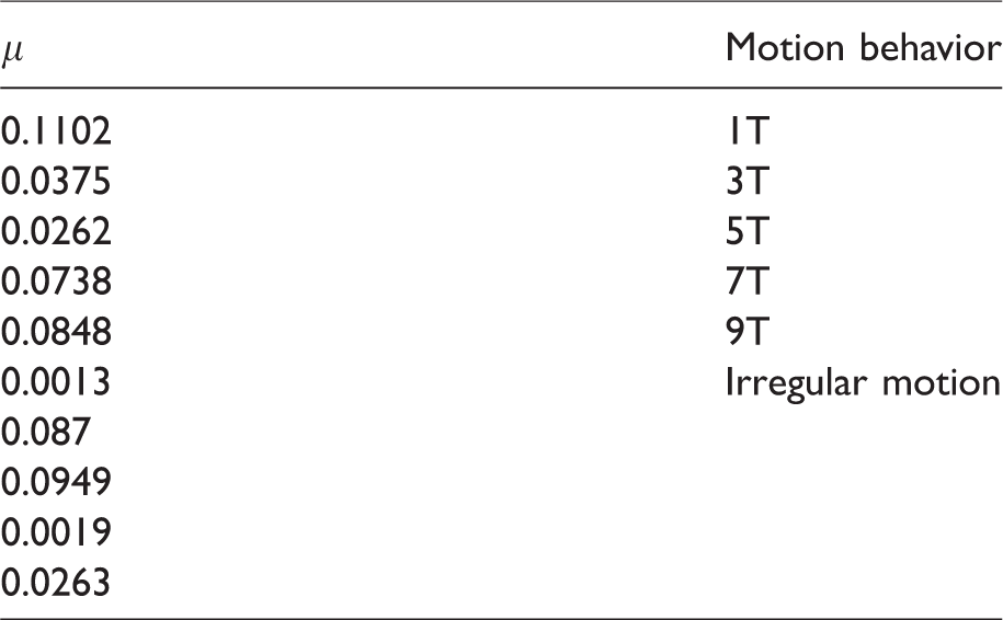
Maximum Lyapunov exponent with different μ value (a) μ = 0.1102; (b) μ = 0.0263.
The above figure shows that when μ = 0.1102, the system is in cyclic motion and its maximum Lyapunov exponent is close to 0. However, when μ = 0.0263, the system maximum Lyapunov exponent >0, system motion is chaotic. Figure 6 shows the maximum Lyapunov exponent when the system damping coefficient μ = [0.0000, 0.2000].
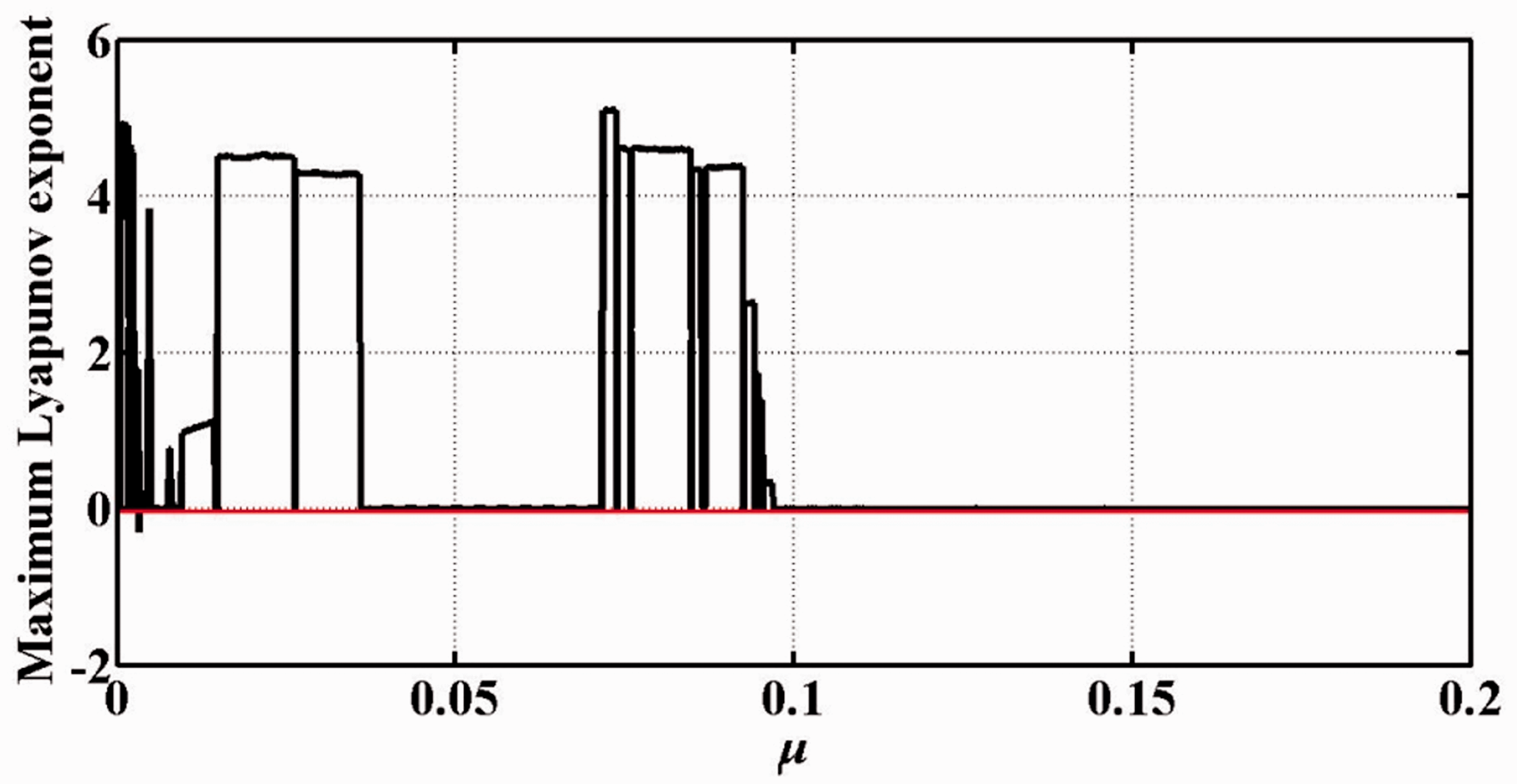
Change in maximum Lyapunov exponent when μ is in the [0.0000, 0.2000] interval.
A bifurcation diagram can be used to observe the splitting phenomenon in a chaotic system. Figure 7 shows that when the system damping parameter μ is in the [0.0000, 0.2000] interval, system y1 and y2 exhibited cyclic and chaotic motion. When system damping parameter μ = 0.2, the bifurcation diagram clearly shows that the system is in a completely chaotic state.
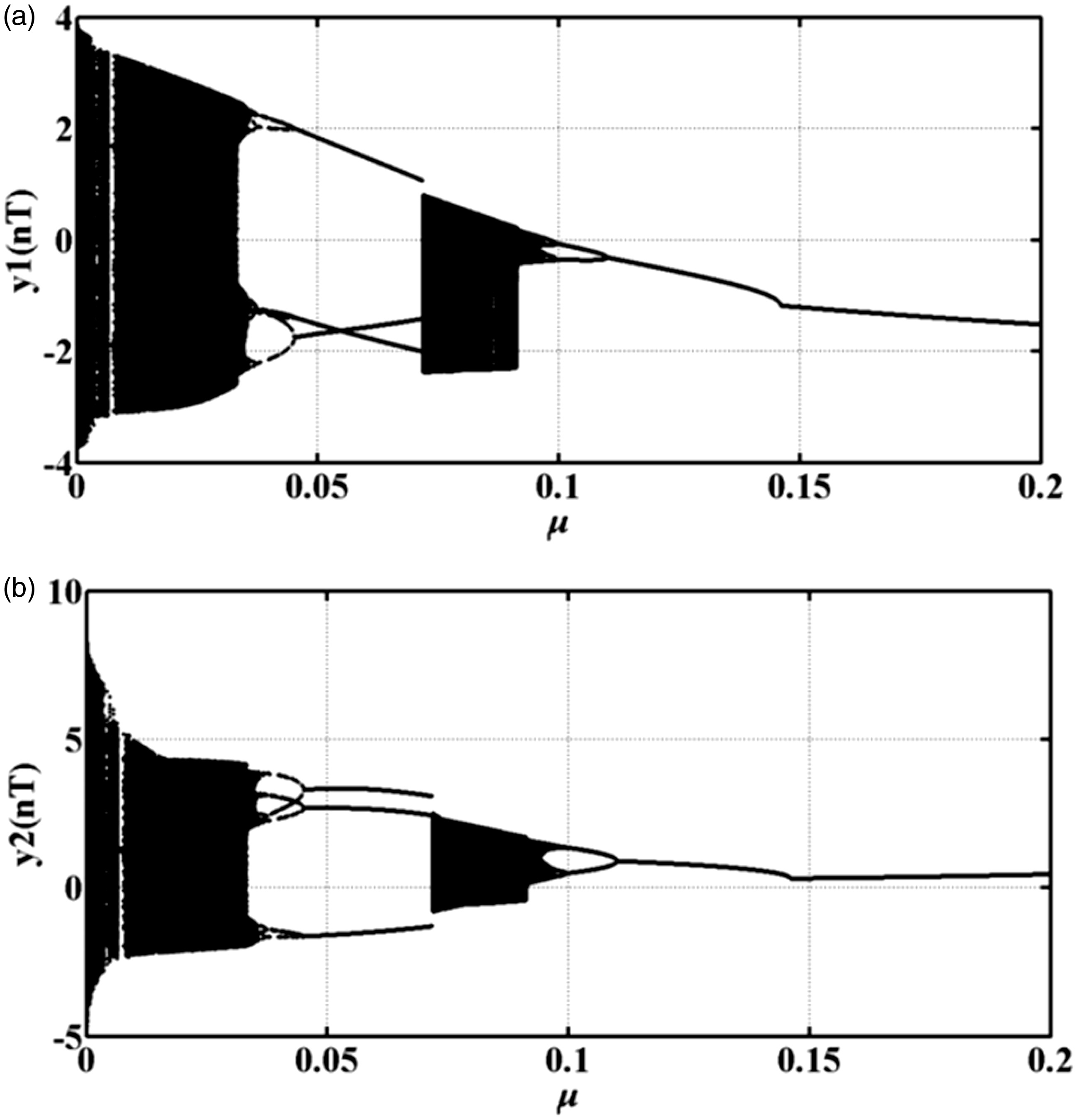
The change in splitting when μ is in [0.0000, 0.2000] interval (a) system y1(nT); (b) system y2(nT).
Controller design
In ‘System dynamic analysis and verification’ section, it was shown that changes in the damping parameter μ can cause the system to exhibit chaotic phenomena and we used SMC to control the system and impose stability. We also used PSO-PID and compared the results to those achieved with the proposed SMC control method.
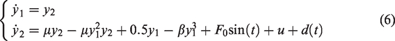
The SMC method has wide application and is easy to realize. When SMC enters the sliding mode, it can track targets rapidly and we added the control item u to the system. The system was then redefined as
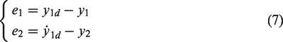
According to equation (8), the sliding function was defined as

According to the definition of the sliding mode, when s = 0, the system response should conform to equation (10)

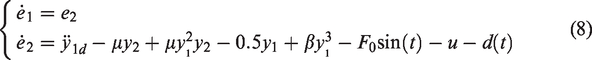
Thus, equation (8) can be rewritten as

The approaching condition is defined as
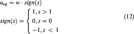
Thus, we designed the SMC controller as

To ensure that this controller is stable, we selected equation (14) as the Lyapunov function and verified its stability
When equation (12) is established and 
Obviously, when
Experimental results
The results of the analyses show that when the system damping coefficient has a specific value, this will result in chaotic behavior. Therefore, we added the PSO-PID and SMC controllers to the hydraulic press electro-hydraulic servo system.
Simulation results
Figure 8 is a phase diagram of the PSO-PID speed control process used to control the system. PSO is used to optimize the system control parameters Kp, Ki, and Kd. Figure 9 shows the phase diagram of the SMC controller used in which y1 represents the system output displacement and y2 represents the system output speed.
Phase diagram of displacement and speed controlled by PSO-PID.
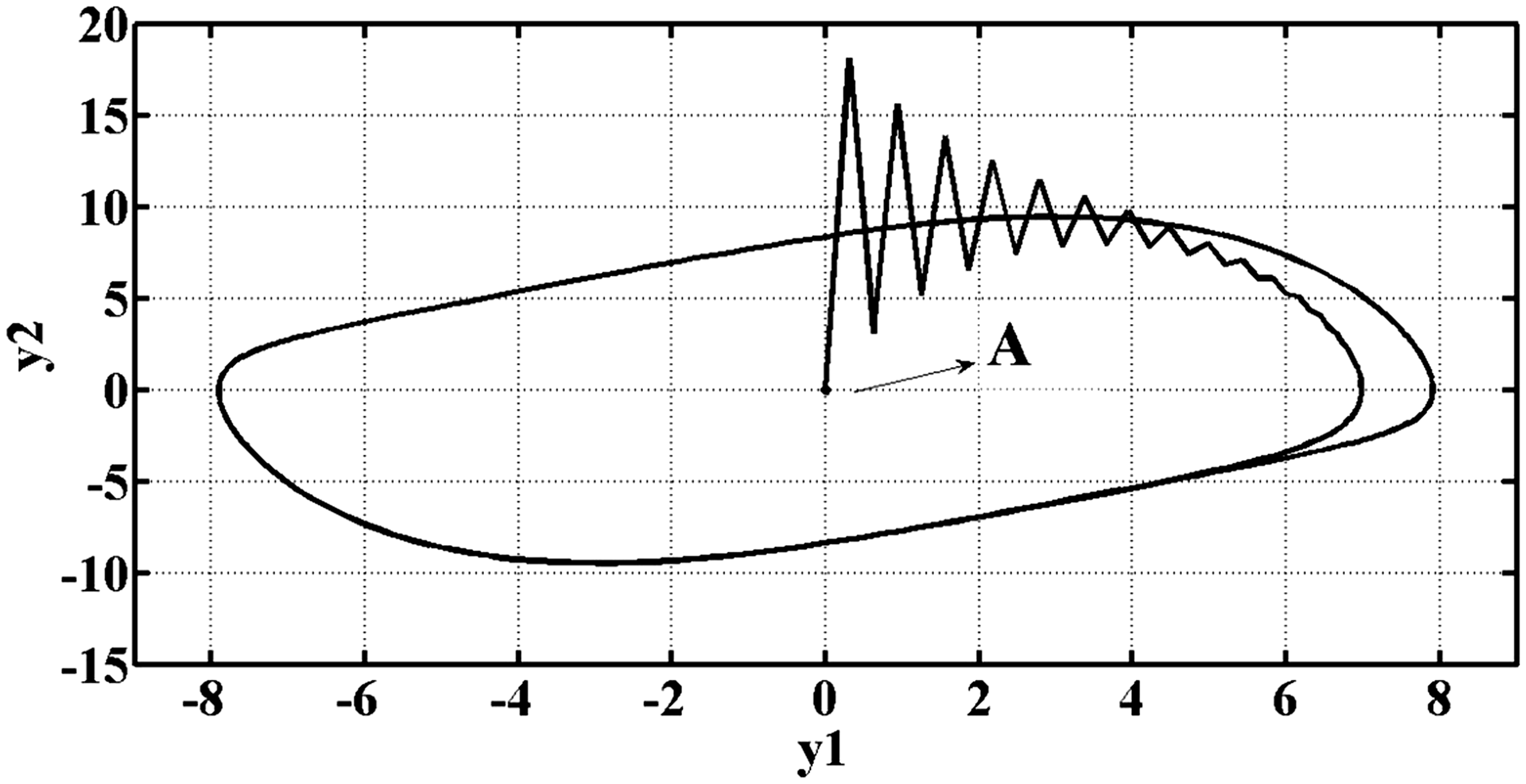
Phase diagram of displacement and speed controlled by SMC.
The time and displacement response shows that when SMC control is used, the transient time and precision are higher than that achieved with PSO-PID (see Figure 10). In the figure, r represents the system input target.
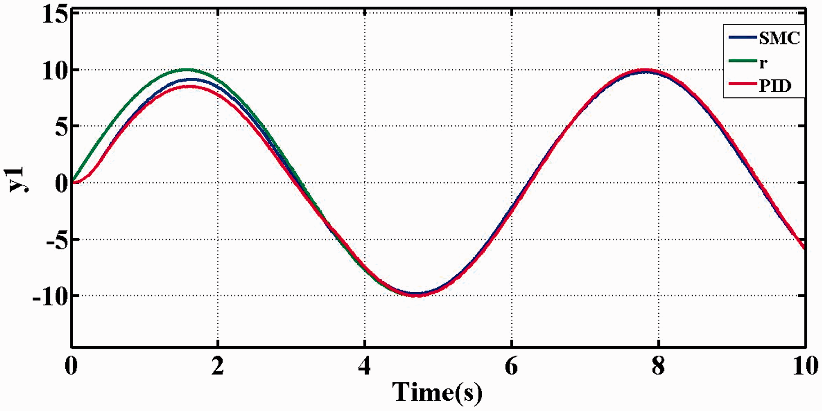
Comparison of input signals r, PSO-PID, and SMC.
Circuit realization
Because the SMC controller gave superior results, only the SMC circuit was realized as a breadboard assembly in the laboratory and used in an actual hydraulic press electro-hydraulic servo system. The simulated circuit was used as a reference for the construction. Basic electronic components and analog ICs were used to form the OP circuit. External excitation signals were used to realize the electro-hydraulic servo system hardware circuit. A signal generator, power supply, and oscilloscope were used in the experiments to observe the system motion. The laboratory experimental mockup is shown in Figure 11.
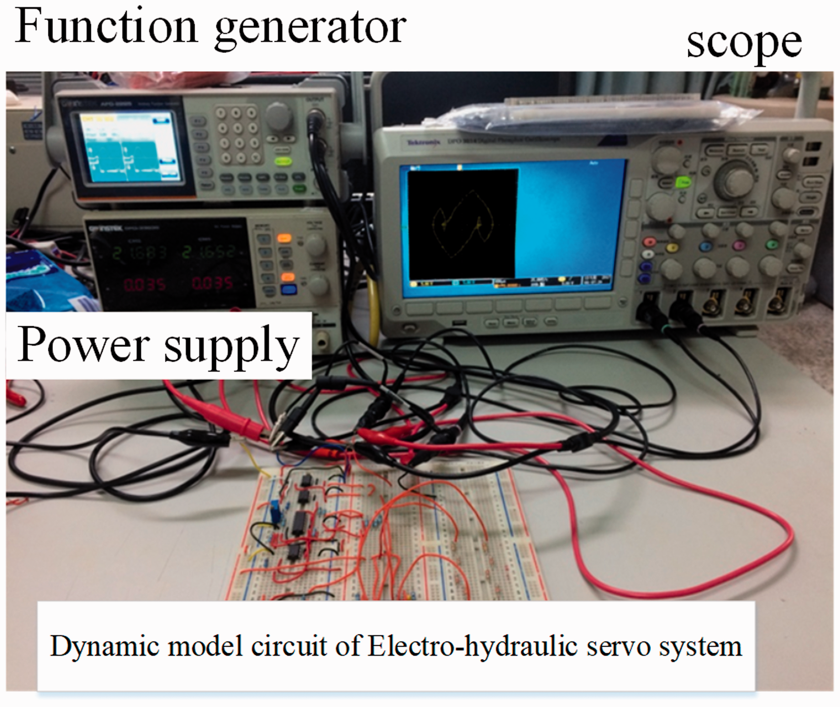
System hardware.
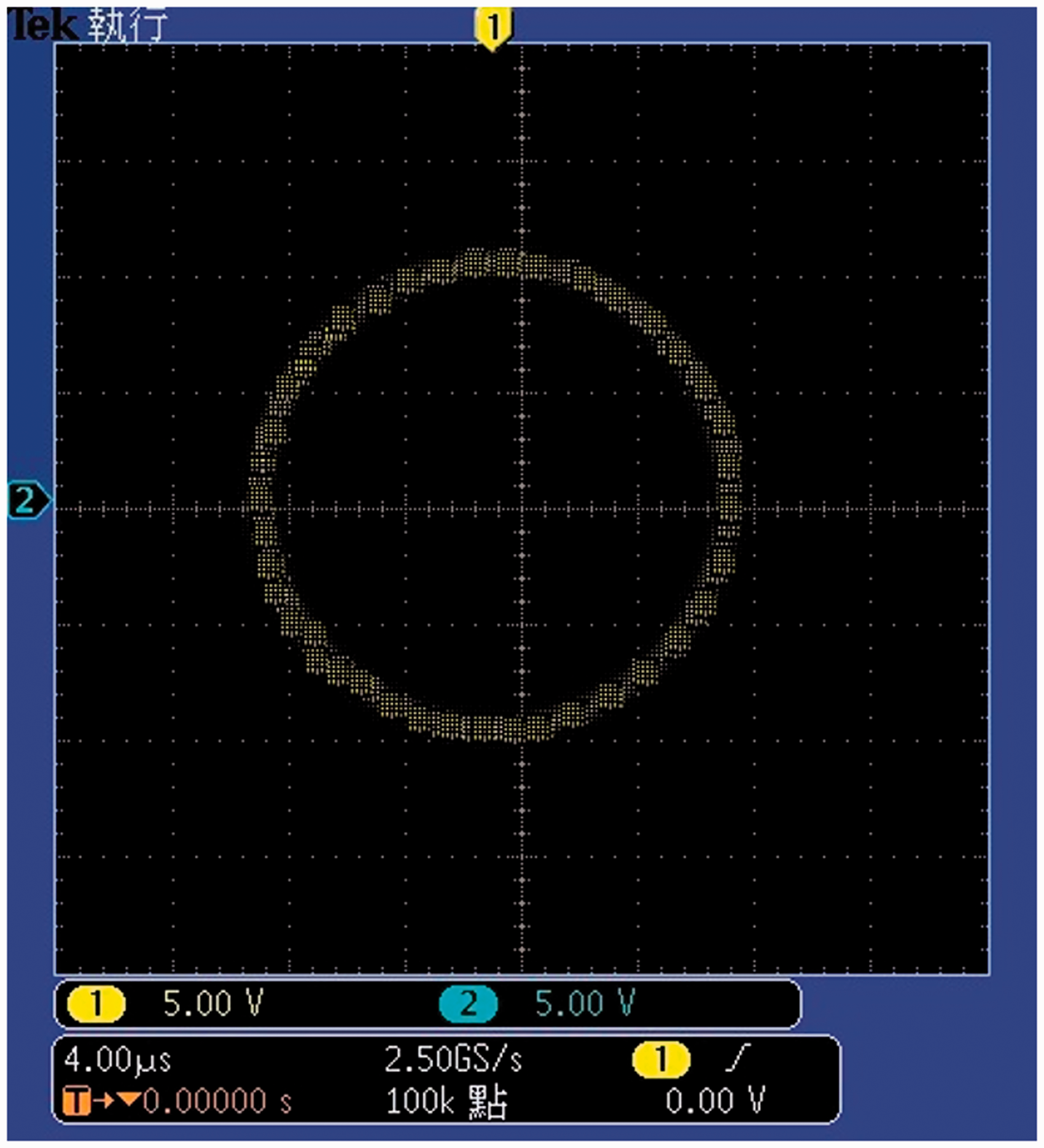
When the system damping parameter μ is 0.0013, the system becomes chaotic as shown in the oscilloscope trace (see Figure 12).
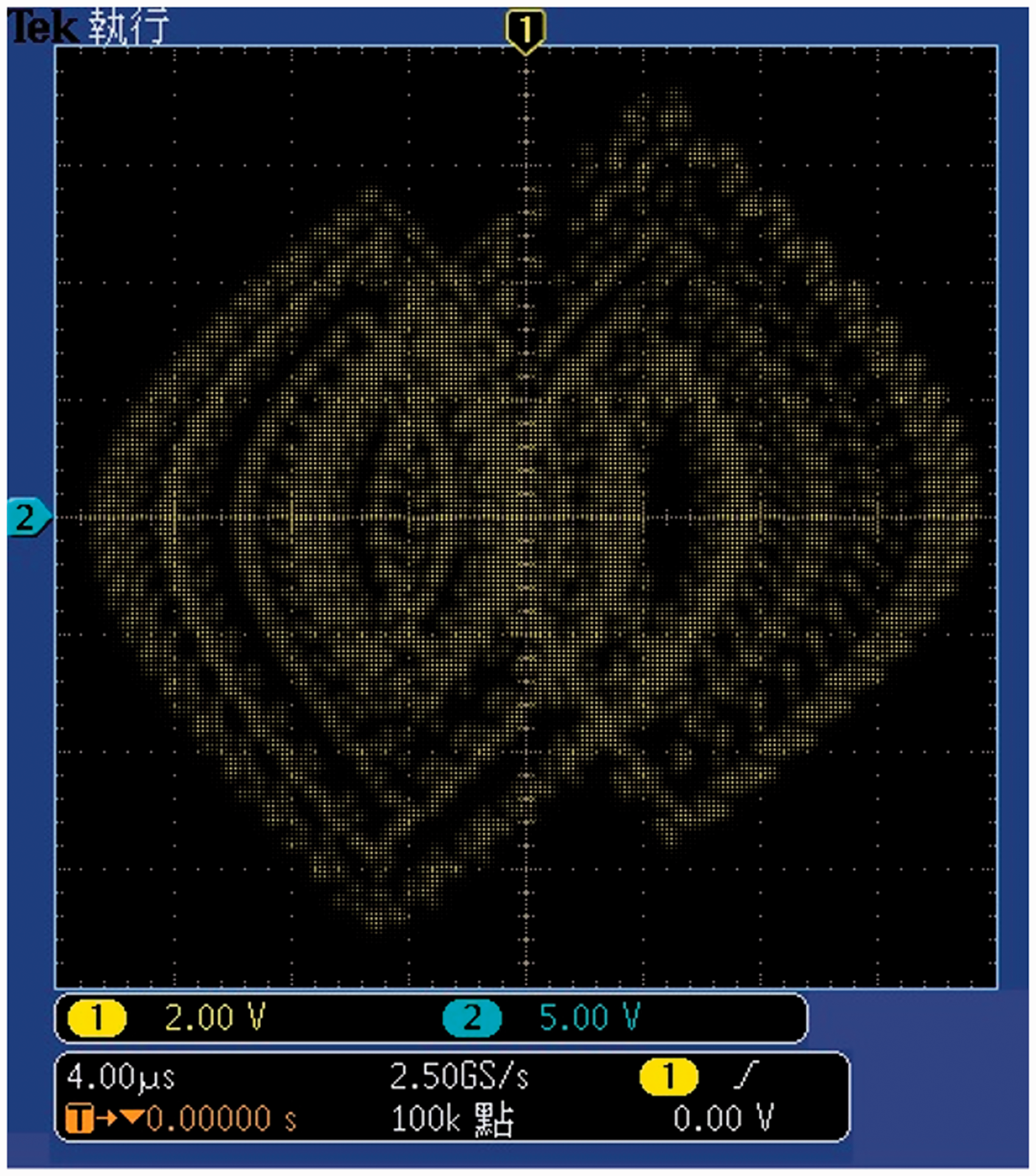
Actual system chaotic oscilloscope trace (μ = 0.0013).
Figure 13 shows the system response when the SMC controller designed for this study was introduced.
Actual system response graph with SMC control (μ = 0.0013).
Conclusion
In this study, we used theoretical derivation to build an initial dynamic model for a hydraulic press electro-hydraulic servo system. Many non-linear factors were included in the model, such as hydraulic spring force, friction, and damping force. Because few studies of non-linear friction have been made, five different numerical value methods were used to analyze the dynamic phenomena resulting from changes made to the friction damping coefficient of the system. The maximum Lyapunov exponent was used to determine and define chaotic phenomena. This showed that the nonlinear factors will cause a considerable amount of complex variation in the system dynamics which may actually damage the system. To prevent system motion from becoming chaotic, we introduced the PSO-PID and SMC control. Finally, we assembled an SMC controller in the laboratory. Experiments showed that the SMC controller gave a superior response and better control of the system and could successfully suppress the unwanted behavior. In future studies, we will analyze comprehensive system characteristics, including the non-linear spring rigidity coefficient and the system damping ratio.
Footnotes
Declaration of conflicting interests
The author(s) declared no potential conflicts of interest with respect to the research, authorship, and/or publication of this article.
Funding
The author(s) received no financial support for the research, authorship, and/or publication of this article.