
Abstract
The KDamper is a novel passive vibration isolation and damping concept, based essentially on the optimal combination of appropriate stiffness elements, which include a negative stiffness element. In this paper, after a short review of the optimal design and the selection of the parameters of the KDamper, the main concept focuses on the implementation of the negative stiffness elements with a set of Belleville (disc) springs. The major benefits of the proposed structure are the size and the robustness of the structure. The theory and the design process of the disc springs are presented thoroughly, as well as of the spiral springs with ground ends, along with an initial structural design. Simulation results from three different case scenarios are demonstrated; for an initial displacement, an initial velocity and an external excitation. The results obtained from the simulations show very satisfactory behavior.
Introduction
The tuned mass damper (TMD) has a long history with numerous applications in the field of vibration isolation. The essential limitation of the TMD is that a large oscillating mass is required in order to achieve significant vibration reduction. Among others, this has prohibited the usage of TMDs in the automotive or aerospace sector. A parallel direction to the various TMD approaches is the concept of introducing negative stiffness elements (or “anti-springs”) for vibration isolation. The central concept of these approaches is to significantly reduce the stiffness of the isolator and consequently to reduce the natural frequency of the system even at almost zero levels, being thus called “Quazi Zero Stiffness” (QZS) oscillators. In this way, the transmissibility of the system for all operating frequencies above the natural frequency is reduced, resulting to enhanced vibration isolation. The negative stiffness behavior is primarily achieved by special mechanical designs involving conventional positive stiffness pre-stressed elastic mechanical elements, such as post-buckled beams, plates, shells, and pre-compressed springs, arranged in appropriate geometrical configurations. Some interesting designs are described in Virgin et al. 1 and Winterflood et al. 2 However, alternatively to elastic forces, other forms of physical forces can be used to produce an equivalent negative stiffness effect, such as gravitational described in Dyskin and Pasternak, 3 magnetic in Robertson et al., 4 or electromagnetic in Zhou and Liu. 5 An interesting approach for a dynamic absorber has been also proposed at Felix et al. 6
The KDamper described in Antoniadis et al. 7 is a vibration absorption concept that overcomes the disadvantages of both the TMD and the QZS. In this paper, the concept of the KDamper is implemented using disc springs. The reasons for which it is selected to implement the negative stiffness with this kind of springs is the fact that they are compact and also because they can withstand heavy loads and stresses. The “Belleville” name comes from the inventor Julien Belleville who in Dunkerque, France, in 1867 patented a spring design which already contained the principle of the disc spring. Disc springs are conical ring washers whose shape changes under axial loads, based on the approximated rotation of the generally uniform rectangular cross-section of the disc around a circle of inversion.
“Basic properties of the KDamper” section introduces the KDamper concept together with a preliminary conceptual presentation on its fundamental concept and on the reasons why this concept offers the potential to overcome the disadvantages of the TMD and the QZS.
“Basic properties of disc springs” section presents the basic properties of the disc springs. All their parameters are displayed, followed by the expressions for the non-linear force and the equivalent stiffness. A parametric analysis is carried out for both force and stiffness to the displacement for different values of the ratio of the maximum displacement to the thickness. In addition, the different configurations of disc springs are cited. Finally, the expressions for the stresses in different points of the spring are given.
“Application” section presents an application of the KDamper concept. The linear negative stiffness element is replaced by a non-linear bistable element, which operates around an unstable equilibrium point. This bistable element takes the form of one Belleville spring (in practice, they are a number of disc springs in series). An effort was made to design the positive stiffness elements with disc springs. The whole design process is thoroughly demonstrated, and all the parameter values for the disc springs are calculated.
In “Model design” section, the parts and the assembly, both designed in Solidworks, of the proposed damper are presented. Firstly, all parts are presented separately, the disc spring for negative stiffness, the disc spring for positive stiffness, and the additional mass and the intermediate ring. In the end, the whole model in normal view, as well as in cross-sectional view, is depicted.
“Response analysis” section presents the results of this research that are the response analysis figures of the designed model. The results have been found for three different cases: (a) for given initial displacement, (b) for given initial velocity, and (c) for an external excitation for different values of the frequency. The figures of the variation of the non-linear stiffness as a function of both time and displacement are given, followed by the figure showing the forces applied on the mass. The external force is almost entirely balanced by the positive and negative stiffness forces, as well as by the inertia of the main mass.
Basic properties of the KDamper
The KDamper always indicates better isolation properties than a TMD damper with the same additional mass. Instead of increasing the additional mass, the vibration isolation capability of the KDamper can be increased by increasing the value of the negative stiffness element. Consequently, significant vibration isolation properties can be achieved, even for very low values (practically insignificant) of the additional mass. Regarding the QZS, they suffer from their fundamental requirement for a drastic reduction of the stiffness of the structure almost to negligible levels, which limits the static load capacity of such structures.
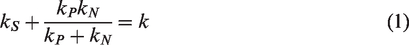
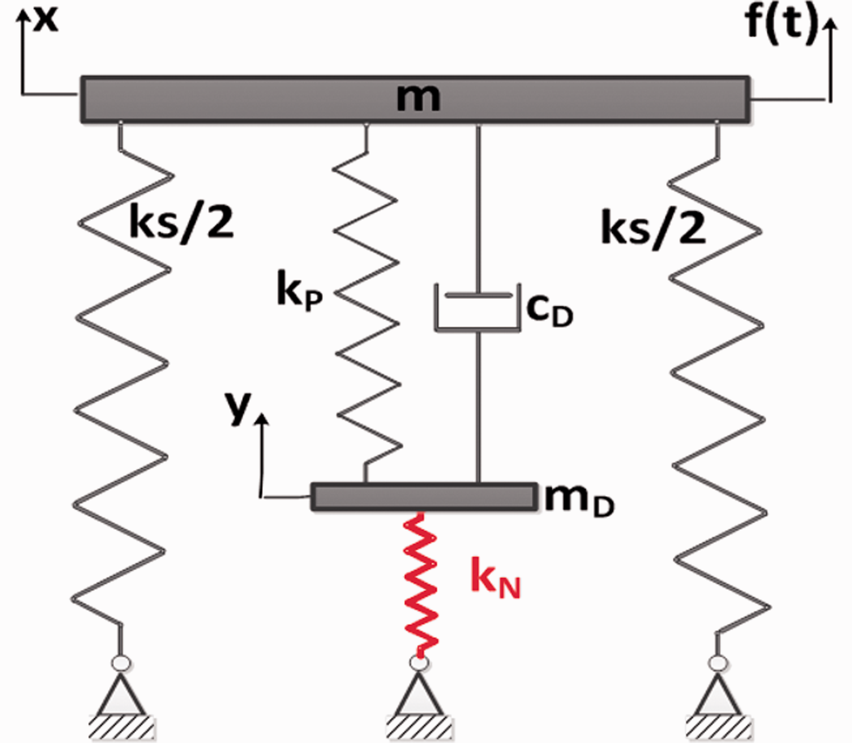
Figure 1(c) presents the fundamental concept of the KDamper. Similarly to the QZS oscillator, it uses a negative stiffness element kN. However, contrary to the QZS oscillator, the first basic requirement of the KDamper is that the overall static stiffness of the system is maintained
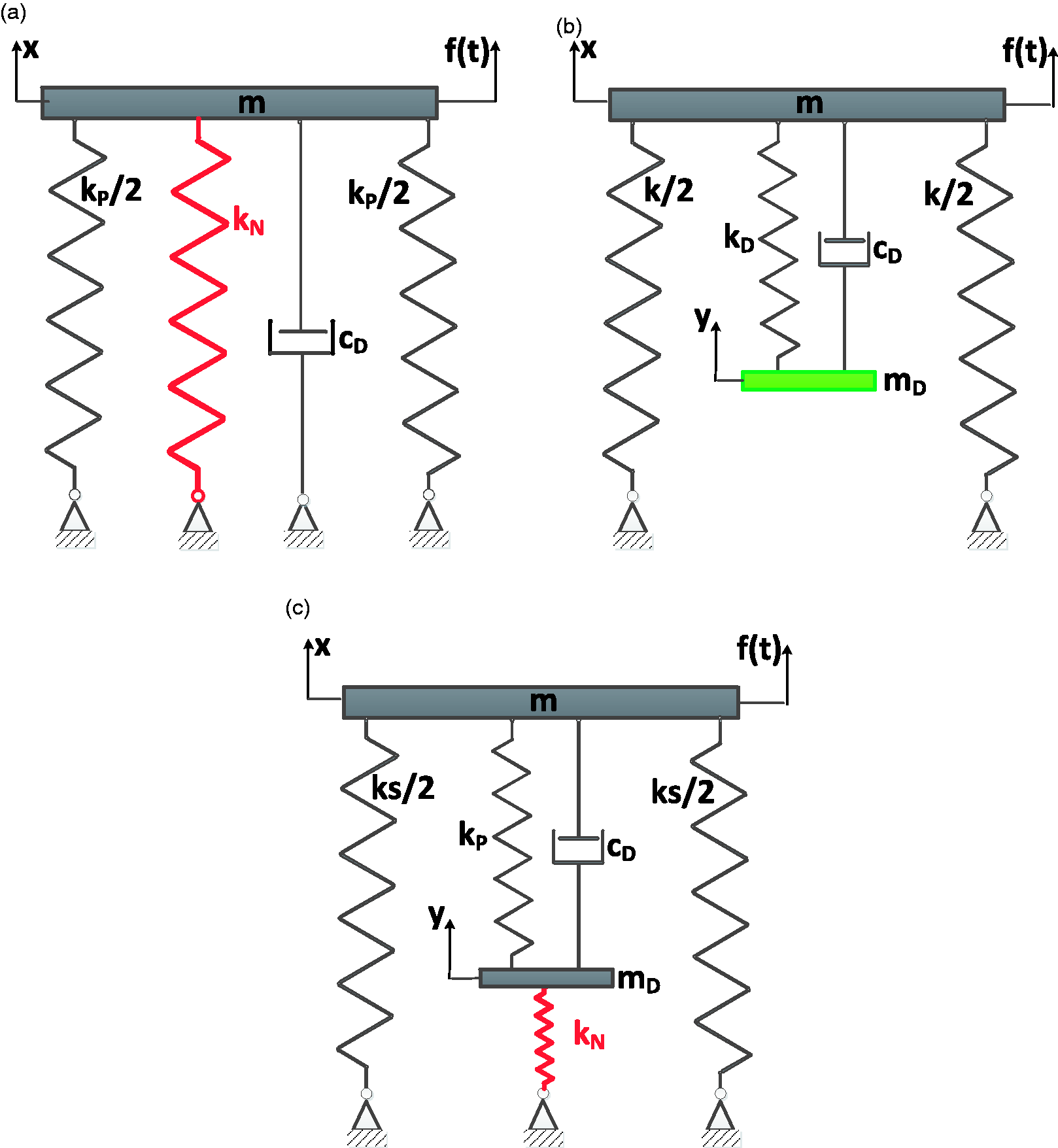
Schematic presentation of the considered vibration absorption concepts (a) quasi-zero stiffness oscillator, (b) tuned mass damper, and (c) KDamper.
In this way, the KDamper can overcome the fundamental disadvantage of the QZS oscillator.
The equation of motion of the KDamper is


Assuming a harmonic excitation in the form


A careful examination of equation (5c) reveals that the amplitude FMD of the inertia force of the additional mass and the amplitude FN of the negative stiffness force


As it can be seen in Figure 1, the KDamper design is similar to the TMD one with adding a negative stiffness element kN. Of course, it should be mentioned that this holds only for negative values of kN.
The optimal selection of the KDamper parameters is described thoroughly in Antoniadis et al. 7 The first property in equation (39) of Antoniadis et al. 7 has to do with the fact that the amplitude of the Transfer Function of the KDamper at the two pick points is less than the maximum amplitude of the Transfer Function of a TMD with equal μ. The addition of a negative stiffness spring reduces the magnitude of the Transfer Function of the TMD. As a result, the Transfer Function of the KDamper shows an important reduction. This means that the maximum value of the Transfer Function can be reduced without increasing the value of μ and so the additional mass. The second property of the KDamper presented in equation (42) in Antoniadis et al. has to do with the fact that the amplitude of the Transfer Function of the KDamper at the two picks tends to zero when κ reaches the maximum limit value. Because there is a limit for the parameter κ, a margin stability parameter ε is selected based on equation (46) of Antoniadis et al. and so the third property of the KDamper can be found.
Basic properties of disc springs
Characteristic values of the disc springs
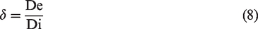
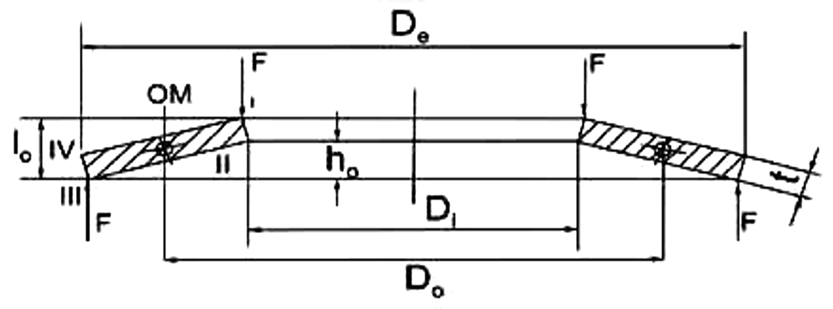
As it can be seen from Figure 2, the basic geometric parameters of a Belleville spring are the outside diameter (De), the inside diameter (Di), the thickness (t), and the total height (h). As given in Bauer,
8
the maximum displacement of the spring is mentioned as

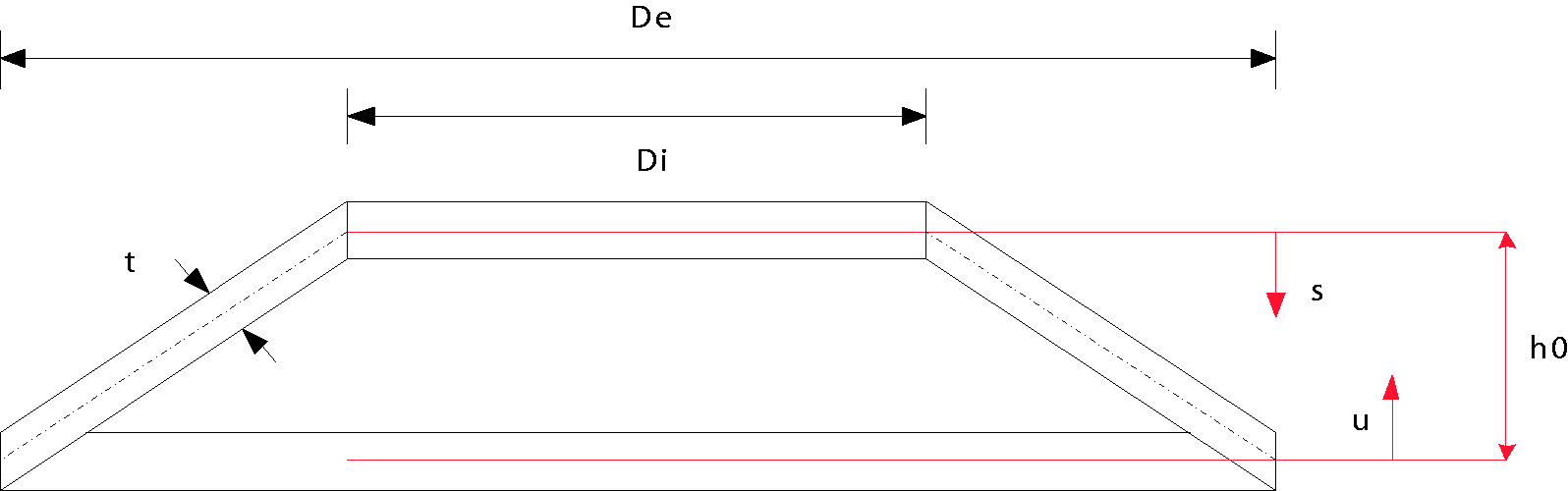
Belleville spring.
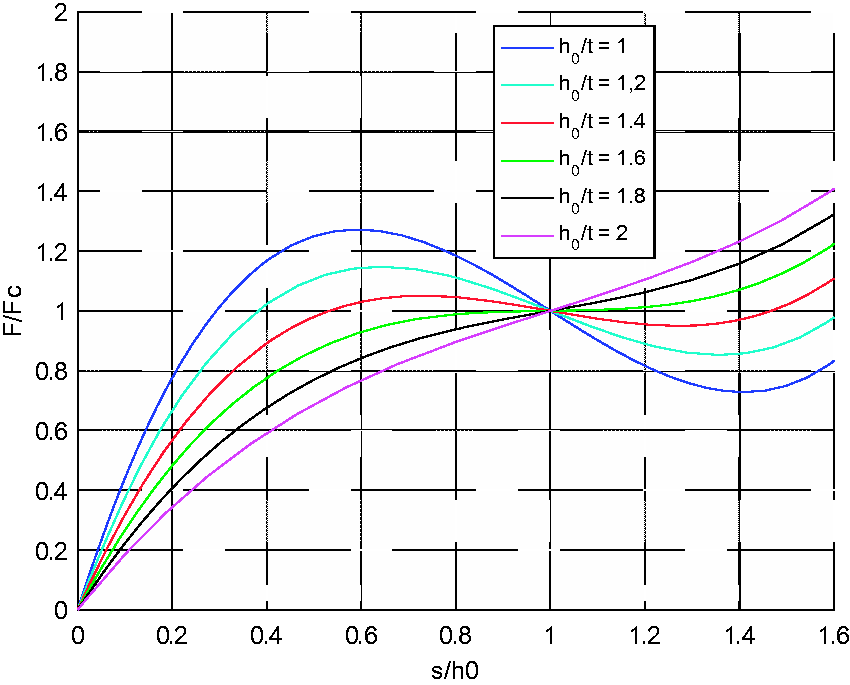
Variation of the non-dimensional non-linear force
Figure 3 presents the variation of the non-dimensional non-linear force as a function of the displacement for different values for ratio of the maximum displacement of the spring over the thickness.
In addition, the ratio of the outside diameter to the inside diameter can be defined as
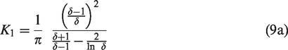
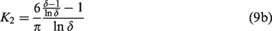
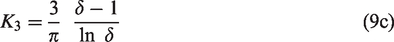
The characteristic values must also be defined as

Force–displacement curve
The following expressions can be derived for the non-linear force


The force provided by a disc spring at the flat position is given by this equation
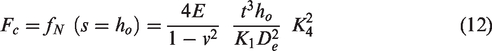
Figure 4 presents the curve of the non-dimensional non-linear force
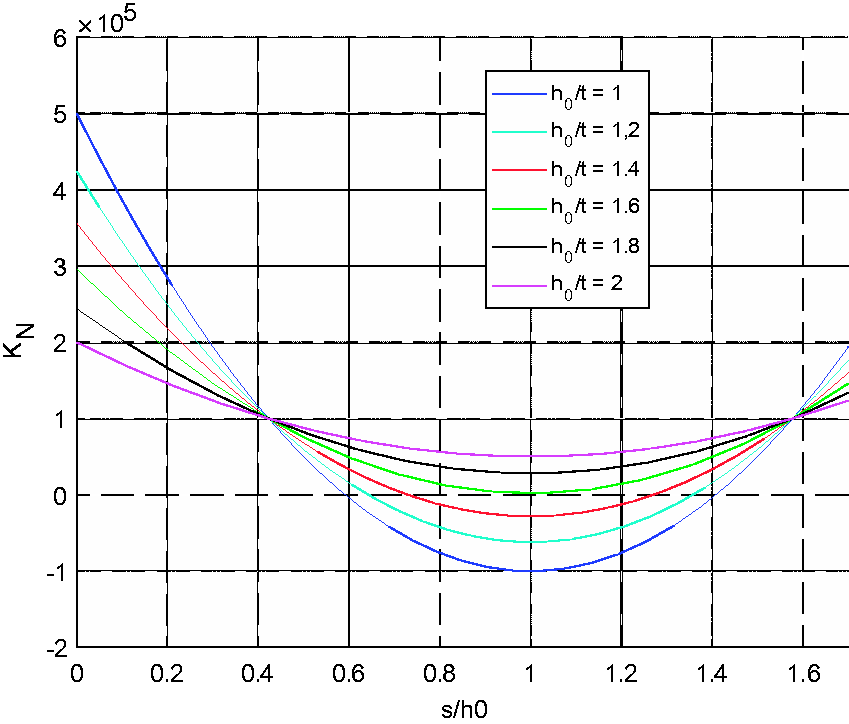
Variation of the non-linear stiffness
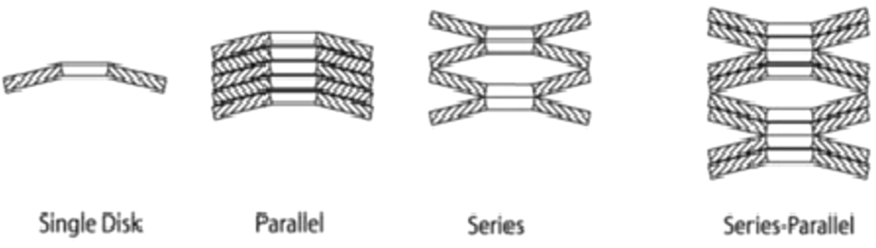
Various configurations of Belleville springs.
Stresses on the disc spring.
Compared to other types of springs, the disc spring can be categorized as having a “small spring displacement coupled with high spring force.” However, this restriction is circumvented by the ability to form stacks of multiple disc springs. Arranging the discs in parallel or nested formation multiplies the spring force, alternating or series arrangement multiplies the spring displacement (Figure 5). Both these stacking methods can be used in combination. Taking into consideration that the disc springs at flat position occupy less space than the conventional springs, more compact structures can be created, being able to withstand heavy loads and stresses (Figure 6).
One of the outstanding characteristics of the disc spring is undoubtedly its capacity for variation of the characteristic force–displacement curve over a wide range. Alongside practically linear characteristics, digressive force displacement characteristics can also be implemented, even those in which spring force diminishes in certain ranges with increasing spring displacement. We can achieve negative stiffness. Many disc springs feature contact surfaces. These are predominantly large parts which in any case involve a high degree of production complexity. In this case, modified calculation methods are used. Contact surfaces improve the guidance properties of disc springs. In some applications, the guiding element of the disc spring stack can have a disturbing influence. Slotted disc springs assume a special role. The slotting process changes the force–displacement range of the individual disc springs, resulting in greater spring displacements coupled with lower spring force. Many disc springs feature contact surfaces. These are predominantly large parts, which in any case involve a high degree of production complexity. In this case, modified calculation methods are used. Contact surfaces improve the guidance properties of disc springs. In some applications, the guiding element of the disc spring stack can have a disturbing influence. Slotted disc springs assume a special role. The slotting process changes the force–displacement range of the individual disc springs, resulting in greater spring displacements coupled with lower spring force.
Disc springs in series or in parallel
The following are the various configurations of the Belleville disc springs:
For i alternating disc springs stacks, the following applies


For n parallel disc spring stacks, the following applies


These two methods can be used in combination according to the demands of the problem.
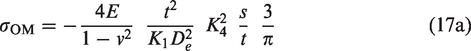
The equations for the stresses in the Belleville springs are


Application
Dynamic equations of the non-linear system
An example for an implementation of the KDamper is now considered. It consists from a mass m which is supported by two parallel linear springs with stiffness kS and kP, respectively, and by a damper with constant cD. The damper cD and the spring kP are also connected to a mass mD.
Considering the example of Antoniadis et al., 7 the main concept is to replace the negative stiffness springs with a number of disc springs (Belleville) in order to get better damping results.
The static equilibrium position of the system is depicted in Figure 7(a), under the action of the gravity force. The perturbed position after an external dynamic excitation f(t) is depicted in Figure 7(b), along with the necessary notation concerning the various displacements of the system.
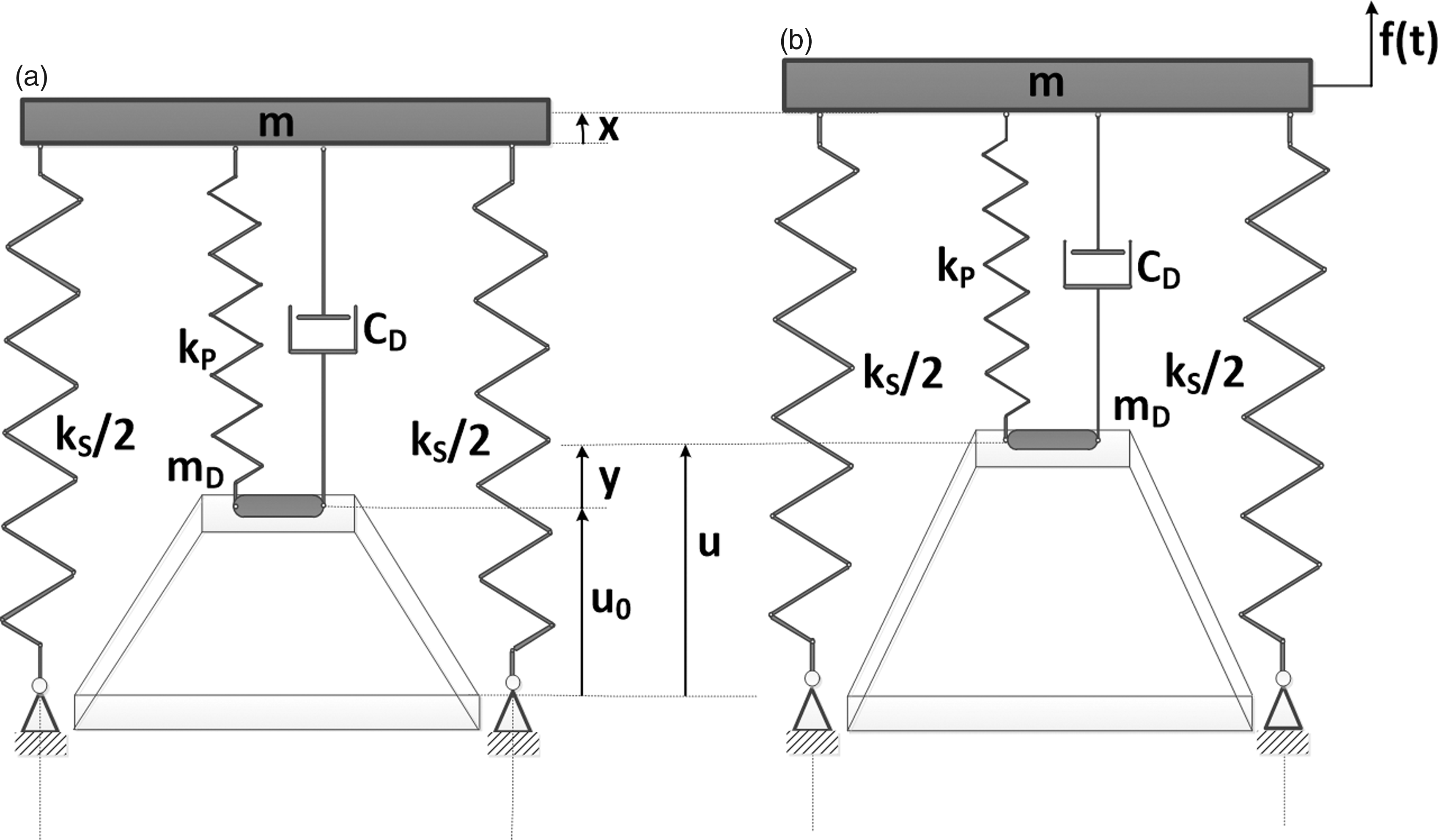
Schematic presentation of the realization of the KDamping concept using a Belleville spring. (a) Configuration at the static equilibrium point. (b) Notation concerning the perturbed configuration.
The linear problem.
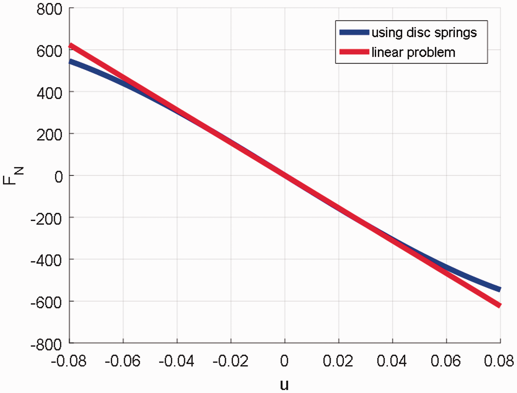
Force–displacement curve of (a) the linear problem (red line) and (b) the appropriate disc springs (blue line).
The equations of motion of the proposed oscillator are


The equations of the system at the static equilibrium point are derived by equations (18a) and (18b)


Denoting by


Further elaboration of the sets of equations (19) to (21) and substitution in the set of equations (18) leads to the final set of equations of motion


Design process
To design the appropriate disc springs, the linear problem (Figure 8) must be solved first. After the selection of the system parameters (it will be presented in the next paragraph), the simulation of the linear problem is the first step.
After the simulation, the force–displacement curve (Figure 9) of the negative stiffness element occurs. The concept is to design a disc spring or a stack of disc springs whose force–displacement curve will fit on the curve of the linear problem. Disc springs are initially compressed to flat position.
Response analysis for the linear system
The mass of the system is selected to be m = 100 kg and the total static stiffness of the system k = 49,050 N/m. The main parameters of the KDamper are selected as in Antoniadis et al. 7 and are μ = 0.01 and κ = 7.8. The full set of the KDamper parameters and the spring stiffness are presented in Tables 1 and 2, respectively. It should be noted that the static stability margin has been found to be ε = 0.05.
Non-dimensional KDamper parameters.

Dimensional KDamper parameters.

It should be noted that if the damping element CD was used to connect directly the mass m to the support (ground), the equivalent damping effect on the system would have been essentially negligible

Figure 10 presents the waveforms of the displacements and the velocities of the linear system to an initial displacement of 0.01 m. As it can be observed at the figure above, the maximum displacement of the mass mD is equal to
Response functions of the linear system to an initial displacement of 0.01 m. (a) Displacements. (b) Velocities.
Selection of the Belleville springs parameters
The next step is the design of the Belleville springs to be used for the non-linear problem. First, the equation above for the non-linear stiffness K is considered.
By setting the derivative of this equation equal to zero, it can be found that when
The following equations must be true


Equation (25) must be true in order not to exceed the limit of the static stability, while equation (26) must be true in order to have an adequate level of damping.
Therefore, from equations (25) and (26), the full set of the Belleville springs parameters can be defined. The full set of the Belleville springs parameters can be found in Table 3.
Belleville springs with negative stiffness parameters.

The value N represents the number of the springs stacked in series formation. In addition, the values E (elasticity modulus) and ν (Poisson ratio) are the characteristic values of the material of which the springs are produced. For the case considered, steel has been used. To increase the maximum displacement for the mass, a stack of 56 springs in series formation has been used.
Considering N number of equal stiffness springs (
The total stiffness 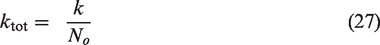
And the maximum displacement of all springs is

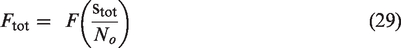
It is important to mention that the total force applied by the stack of the springs is equal to this applied by the one spring and so
In addition to all the above, the proposed model in Antoniadis et al. 7 has been improved by replacing also the inside positive stiffness spring (kp) by a set of Belleville springs.
The parameters of the designed springs are presented in Table 4.
Belleville springs with positive stiffness parameters.

It should be mentioned that the material used is the same for all springs (steel). Finally, compression coil springs with ground ends are used to implement the exterior stiffness.
As it is mentioned in Khurmi and Gupta, 10 the equations for the parameters of the springs are
The free length of the spring can be found as

The spring length in flat position can be found as

The spring stiffness can be found as
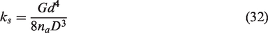

By solving for 
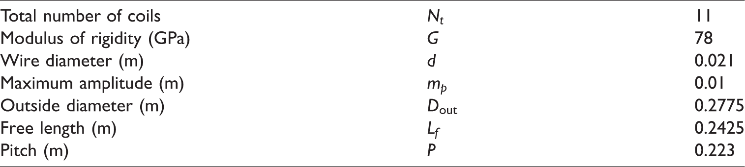
There has been designed a set of four parallel coil springs with their parameters presented in Table 5.
Normal springs parameters.
Model design
An initial model has also been designed in Solidworks and is presented in Figures 11 and 12. The negative stiffness disc springs are initially compressed with a screw. Disc springs are held in position relative to each other by intermediate rings with T-shaped cross-section (Figure 10(d)), which act also as guide elements. Between the two different types of disc springs, the damping mass acts also as an intermediate ring and has a hole with an interior thread where the screw is screwed.
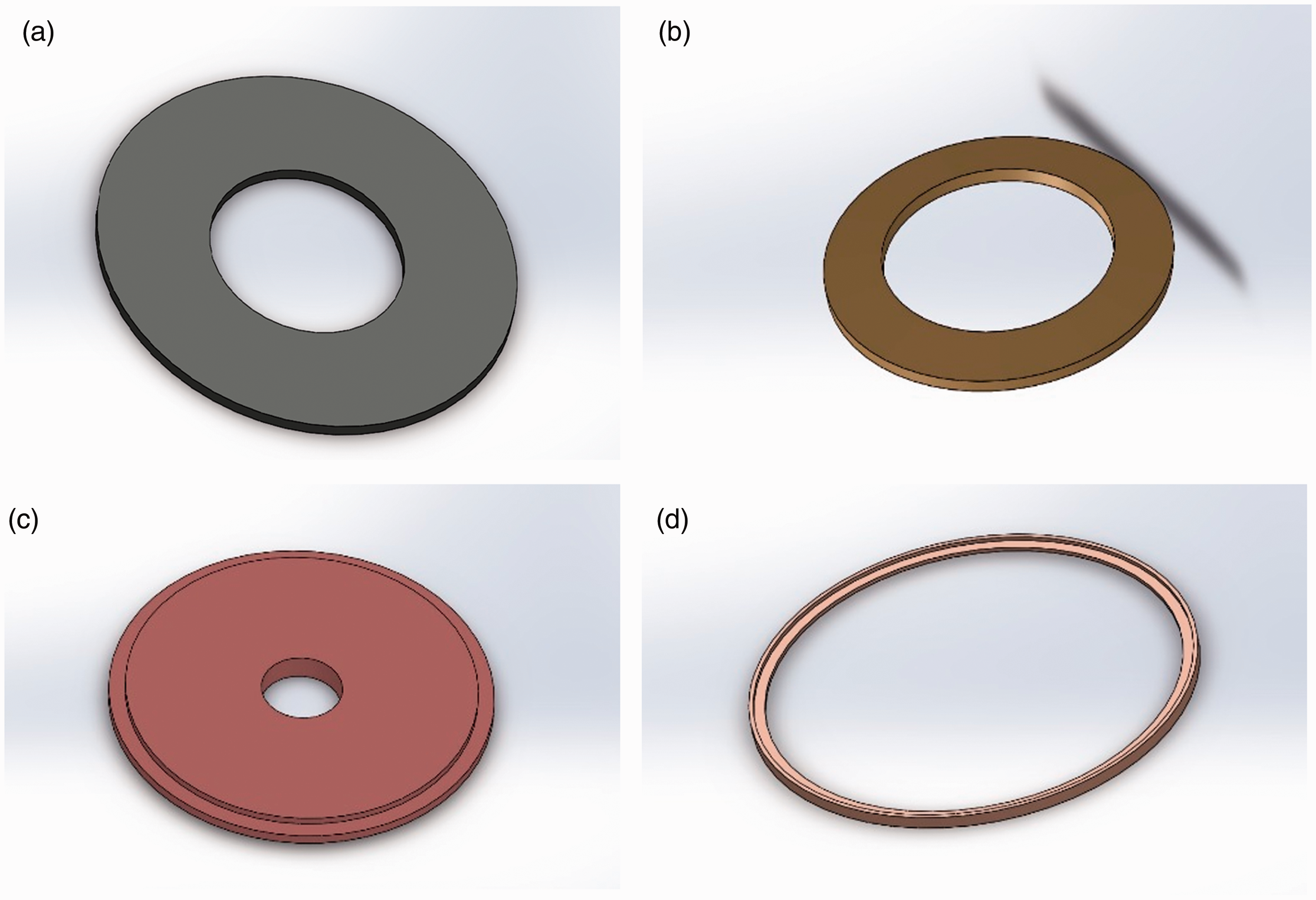
Solidworks model for (a) negative stiffness Belleville spring, (b) positive stiffness Belleville spring, (c) interior mass, and (d) intermediate ring.
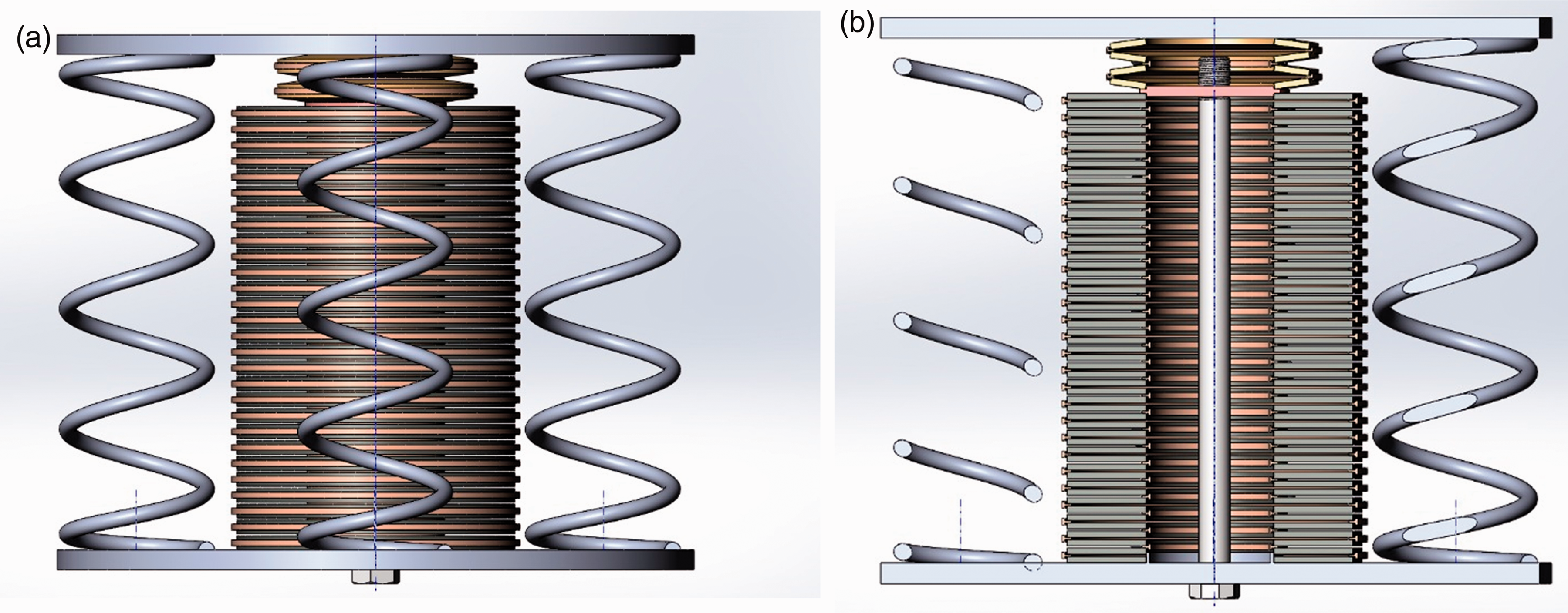
Solidworks model. (a) Full view. (b) Cross-sectional view.
Response analysis
Response analysis for initial displacement
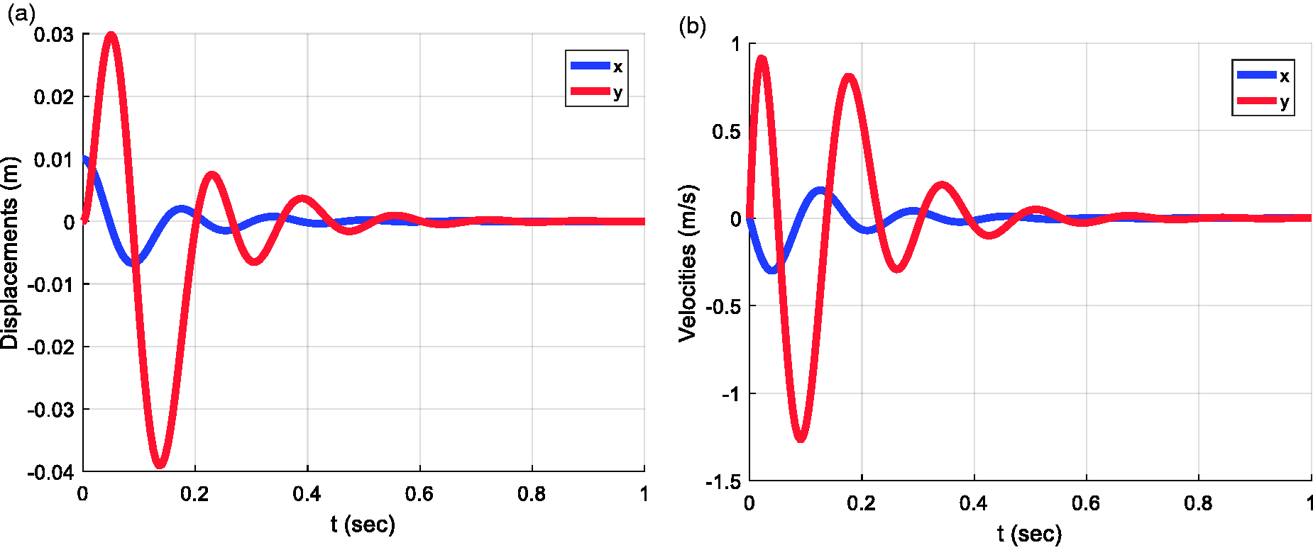
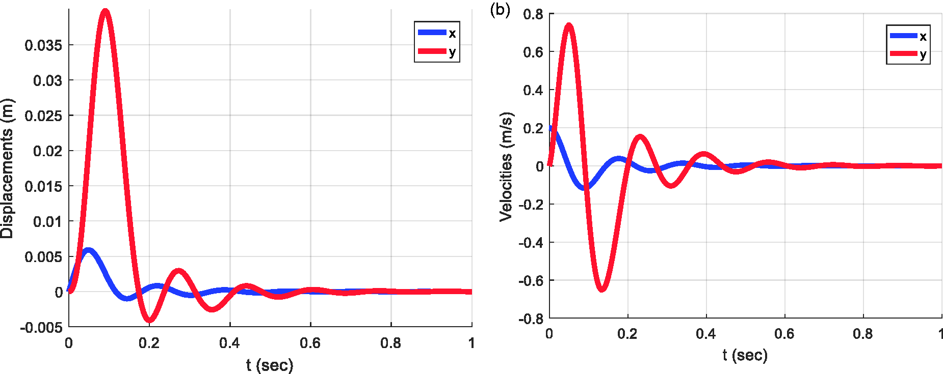
Figure 13 presents the waveforms of the displacements and velocities of the response of the non-linear oscillator to an initial displacement of 0.01 m.
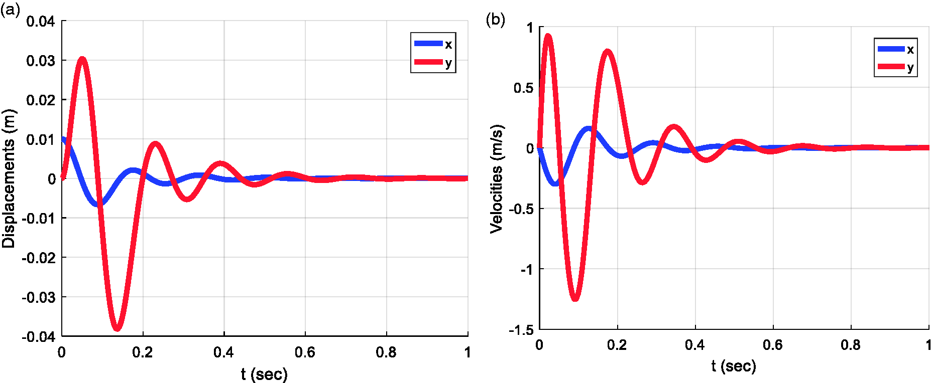
Response of the KDamper configuration to an initial displacement of 0.01 m. (a) Displacements. (b) Velocities.
Figure 14 presents the response function of the TMD for the initial displacement of 0.01 m. To get this result, the non-linear stiffness kN is set equal to zero. As it can be seen, there is a great difference at the damping results compared to KDamper case. This difference has to do with the bigger additional mass needed by the TMD. This is the most remarkable drawback of the TMD compared to the KDamper. In addition, the time needed from the TMD to give the same damping results with the KDamper is found to be greater than 300 s.

Response function of the tuned mass damper to an initial displacement of 0.01 m.
Figure 15(a) presents the variation of kN over time and Figure 15(b) as a function of the displacement u of the Belleville springs. A significant variation of kN is observed, verifying the strong non-linear nature of the response. However, the negative stiffness kN remains within the specified acceptable limits, which guarantee both static stability and damping behavior.
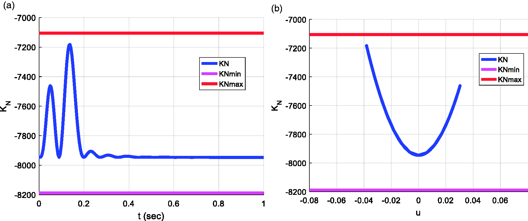
Variation of the non-linear stiffness kN to an initial displacement 0.01 m. (a) Variation in the time domain. (b) Range of oscillation.
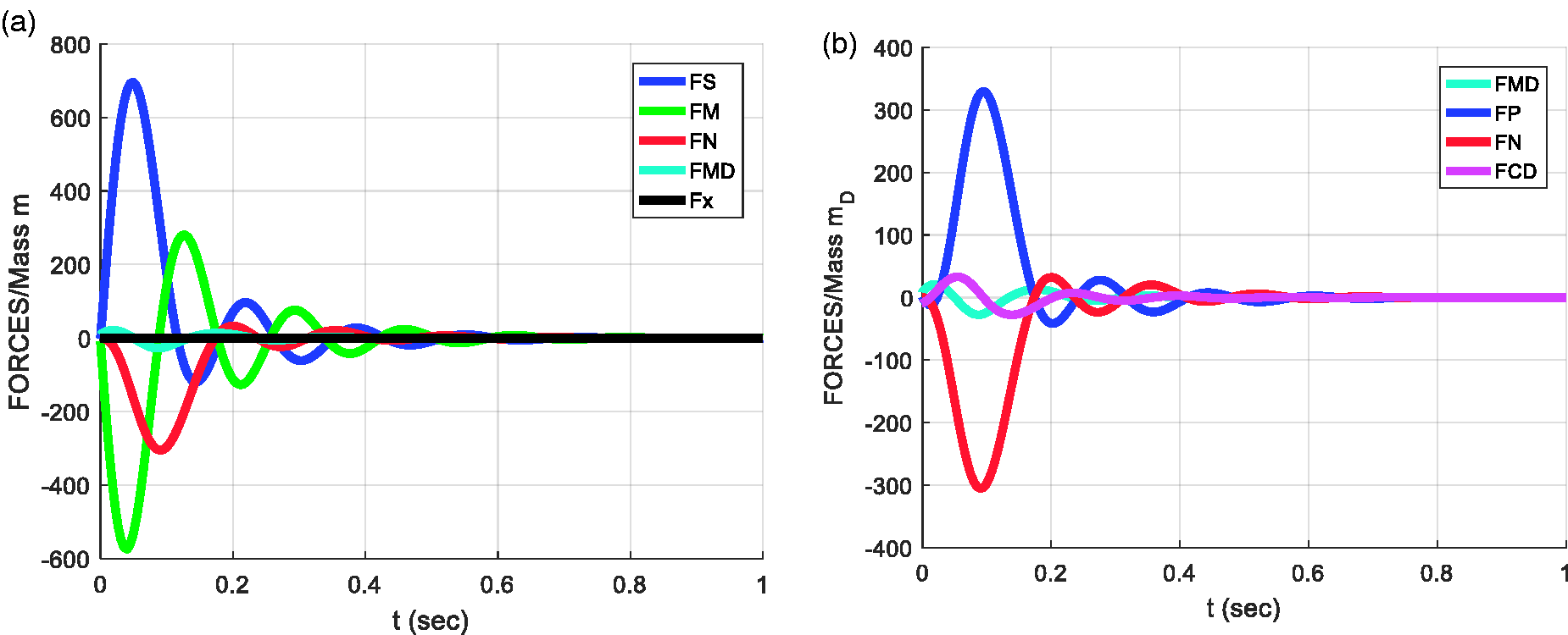
Figure 16 presents the waveforms of the forces. It should be mentioned that
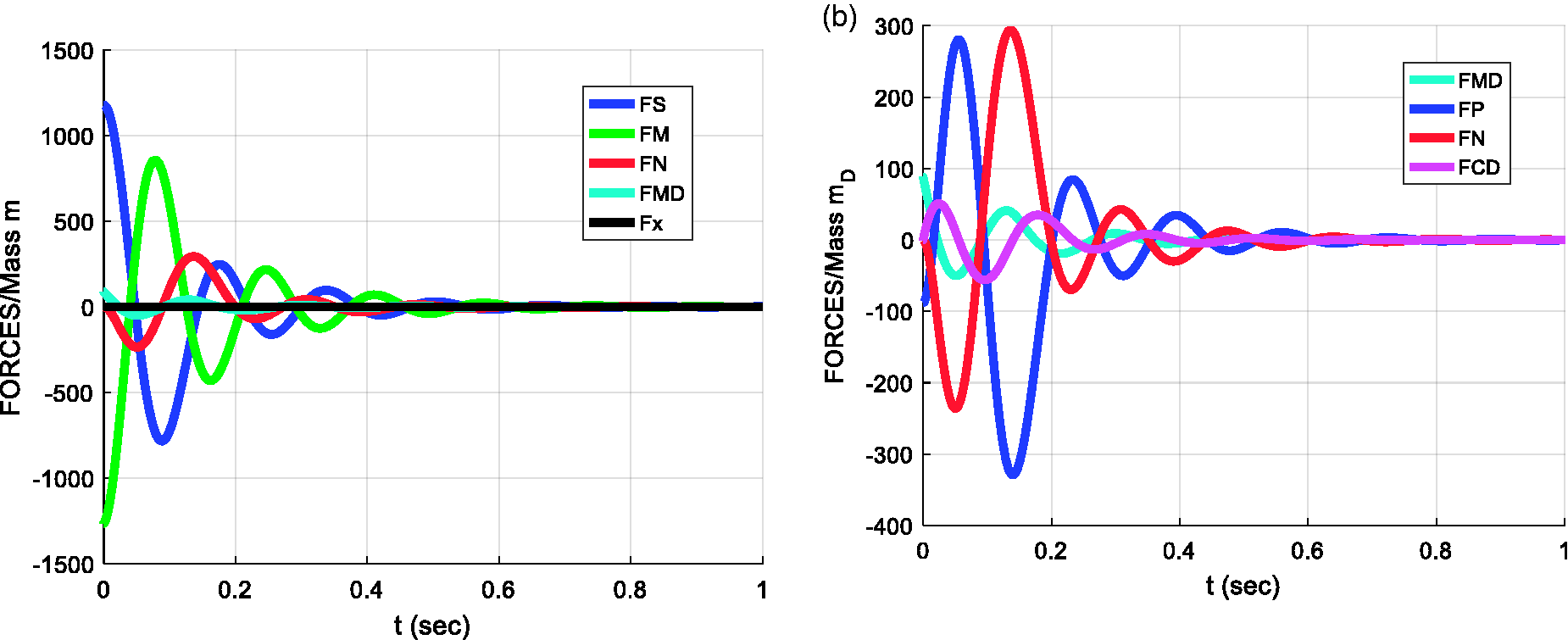
Waveforms of the various force types of the KDamper to an initial displacement 0.01 m. (a) Forces at the mass m. (b) Forces at the mass mD.
The next step is to check the stresses for the proposed structure.
As it can be seen in Figure 17, all stresses are in the allowed limits, as the yield strength for the material proposed (steel) is 1100 MPa.
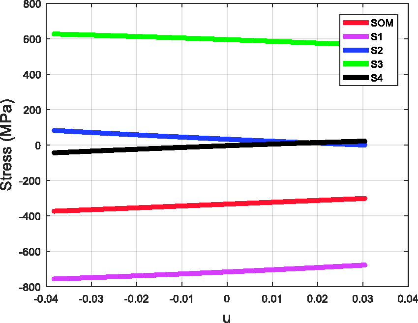
Stresses in the Belleville spring for an initial displacement 0.01 m.
Response analysis for initial velocity
Figure 18 presents the waveforms of the displacements and velocities of the response of the non-linear oscillator to an initial velocity of 2.5 m/s.
Response of the KDamper configuration to an initial velocity of 2.5 m/s. (a) Displacements. (b) Velocities.
Figure 19 presents the variation of the force FN as a function of the displacement u of the Belleville springs. The red color represents the theoretical curve and the blue the real one.
Variation of the force FN as a function of the displacement u.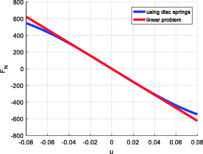
Figure 20(a) presents the variation of kN over time and Figure 20(b) as a function of the displacement u of the Belleville springs. A significant variation of kN is observed, verifying the strong no-linear nature of the response. However, the negative stiffness kN remains within the specified acceptable limits, which guarantee both static stability and damping behavior.
Variation of the non-linear stiffness kN to an initial velocity of 2.5 m/s. (a) Variation in the time domain. (b) Range of oscillation. Waveforms of the various force types of the KDamper to an initial velocity of 2.5 m/s. (a) Forces at the mass m. (b) Forces at the mass mD.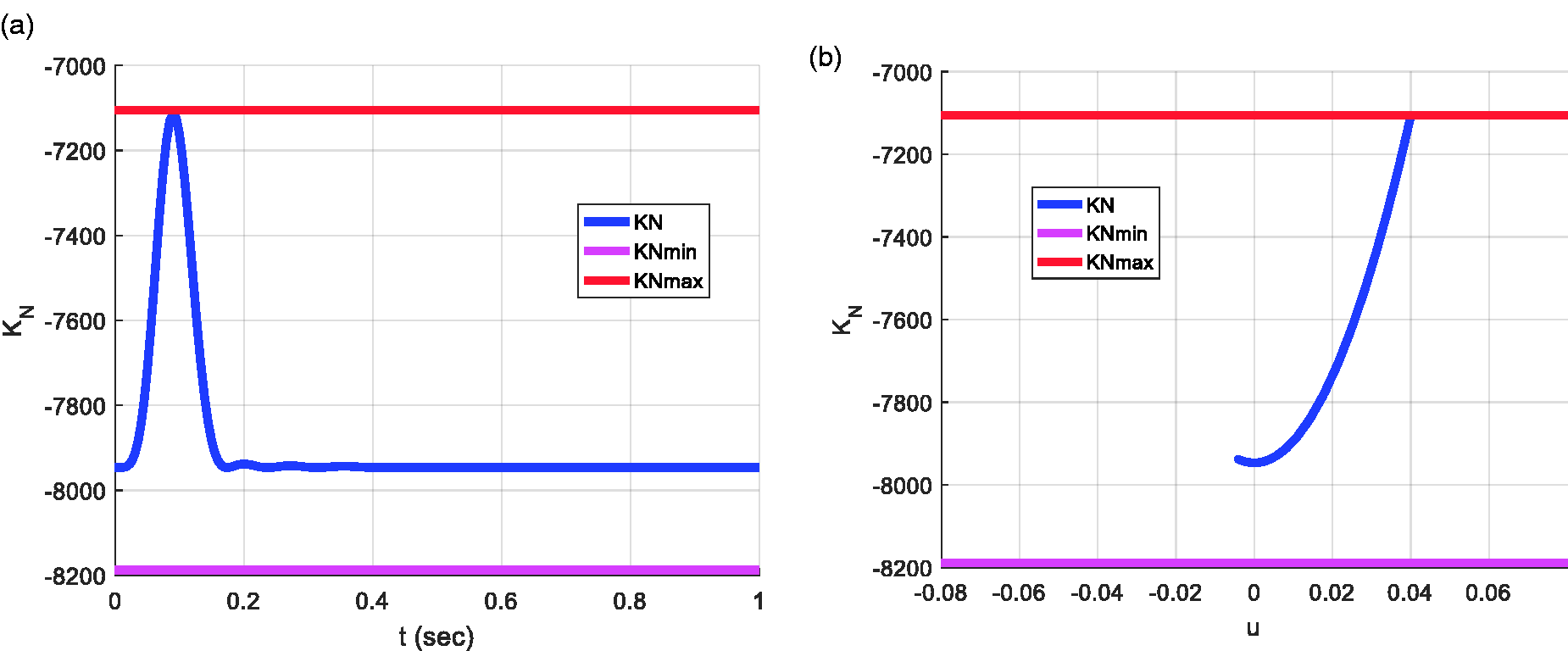
As it can be seen in Figure 22, all stresses are in the allowed limits as the yield strength for the material proposed (steel) is 1100 MPa.
Stresses in the Belleville spring for an initial velocity of 2.5 m/s.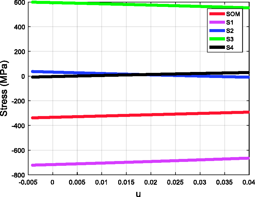
Response analysis for external excitation
Figure 23 presents the transfer function for the linear system for x that corresponds to the displacement of the mass m.
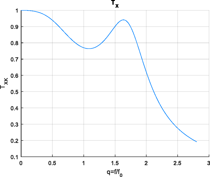
Transfer function for the displacement x of the linear system.
Figure 24 presents the waveforms of the displacements and velocities of the response of the non-linear oscillator to an external force with
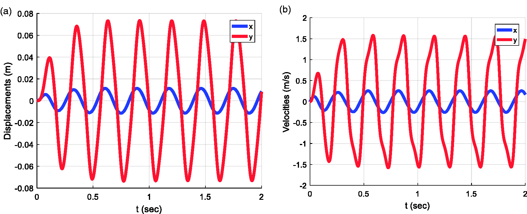
Response of the KDamper configuration to an external force with f = 3.5 Hz. (a) Displacements. (b) Velocities.
Figure 25 presents the waveforms of the displacements and velocities of the response of the non-linear oscillator to an external force with
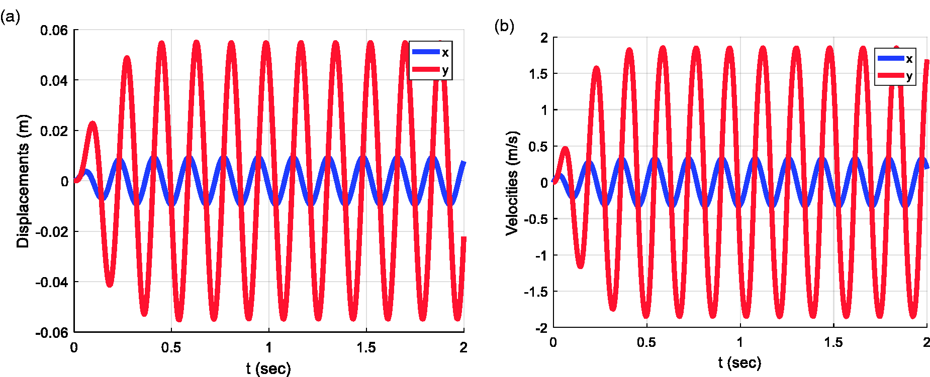
Response of the KDamper configuration to an external force with f = 5.6 Hz. (a) Displacements. (b) Velocities.
As it can be noted, comparing Figures 24 and 25 with the curves for x and y for the two different values of the frequency, for one equal to the resonant frequency of the system, the amplitude is smaller.
Conclusions
The design process demonstrated in this paper leads to the implementation of the KDamper concept using disc springs. As it has been cited, the proposed structure offers far better results than the TMD. More technological advantages can emerge over other isolators in terms of weight, complexity, and reliability, without any need for compromises in the overall stiffness of the structure.
As far as disc springs are concerned, they can be an easy and effective design for negative stiffness concepts, as the ability to adjust the force–displacement curve according to the problem’s demands can prove very useful in low-frequency vibration isolation concepts. The major benefits of this structure comparing it to the one described in Antoniadis et al., 7 where the mechanical complexity can be a suspending factor at the design, are the size and the robustness of the structure.
The concept presented consist a general vibration absorption concept that can be applied also for the design of advanced materials or complex structures. This means that it presents the potential for numerous implementations in a large variety of technological applications.
Footnotes
Acknowledgments
The first author would like to express his sincere thanks to the “The Foundation for Education and European Culture” for the financial support he was granted for his PhD studies during which this work was implemented.
Declaration of conflicting interests
The author(s) declared no potential conflicts of interest with respect to the research, authorship, and/or publication of this article.
Funding
The author(s) disclosed receipt of the following financial support for the research, authorship, and/or publication of this article: This work was supported by the Foundation for Education and European Culture.