
Abstract
This study focuses on integrating an active vibration controller into the finite element model of a piezoelectric laminated plate with the controller–structure interactions considered. A finite element model of a piezoelectric laminated plate is formulated using the third-order shear deformation theory. A state-space model is set up by performing a system identification technique. The state-space model is then used to design an optimal vibration controller. Considering that the finite element model is more appropriate than state-space model for dynamic simulation, the state-space model-based controller is integrated into the finite element model to capture the controller–structure interactions. The results obtained by applying vibration controller in state-space model are also presented to make a comparison. It is numerically demonstrated that the controller–structure interactions occur and cause performance degradation in case that the state-space model-based controller works with the finite element model. There is no prior guarantee that a state-space model-based controller satisfying the control requirements still works well in closed loop with the finite element model. The results of this study can be used to evaluate the controller performance for the piezoelectric smart structures during the preliminary design stage.
Keywords
Introduction
The attempts at solving vibration control of lightweight, flexible, and lightly damped structures, such as satellites and other large-scale space structures, have stimulated extensive researches into smart structures over the past years. A smart structure is capable of sensing and reacting to its environment in a desired manner through the integration of sensors, actuators, and associated control systems. There are a number of smart materials available that can be integrated into the smart structures, such as electrorheological fluids, shape memory alloys, piezoelectric materials, and magnetostrictive materials. Among all these materials, piezoelectric materials, such as lead zirconate titanate (PZT) and polyvinylidene fluoride (PVDF), are widely used as sensors and actuators owing to their intrinsic piezoelectric-mechanical coupling effects, rapid response, and large force transmission. Consequently, the study of laminated composites with surface bonded or embedded piezoelectric materials has attracted many researchers recently because of their potential benefits in shape control, vibration suppression, and damage detection. The design of piezoelectric laminated smart structures relies upon multidiscipline knowledge, such as mechanics, mechanical engineering, and control theory.
For the purpose of vibration control of a piezoelectric laminated smart structure, it is first required to investigate its dynamic characteristics. The finite element (FE) method is capable of dealing with the piezoelectric smart structures.1–3 It has been widely accepted that one of the pioneering works in FE modeling of piezoelectric smart structures is due to Allik and Hughes 4 who investigated the electricity–elasticity interactions using a solid element. Following this research, numerous FE models have been developed to analyze the dynamic behaviors of piezoelectric smart structures. Due to the geometric characteristics of piezoelectric laminated structures, one-dimensional models and two-dimensional models are often used, which include the classical laminated plate theory,5–7 first-order shear deformation theory,8,9 and third-order shear deformation theory (TSDT).10,11 The classical laminated plate theory is based on the Kirchhoff–Love assumption in which the transverse shear deformation effects are neglected. The first-order shear deformation theory implies a linear displacement variation through the thickness and results in a constant transverse shear strain through the thickness, so it needs a shear correction factor which is very difficult to be determined especially for arbitrarily laminated composite structures with piezoelectric layers. The TSDT accommodates quadratic variation of transverse shear strains and eliminates the transverse shear stresses on the top and bottom of a laminated composite plate. Accordingly, no shear correction factor is required in the TSDT. Another model for thick laminated composite structures is based on a layerwise theory12,13 which assumes a biquadratic model for the electric potential distribution along the thickness. These models have their own advantages and disadvantages in terms of accuracy, speed of convergence, and computational cost. Mackerle 14 and Benjeddou 15 have presented a detailed bibliographical review of the FE methods applied to the analysis and simulation of smart piezoelectric structures.
In general, a FE model must include many degrees of freedom (DOFs) in order to obtain an accurate prediction of the dynamical behavior. However, a model with a large number of DOFs is not really suitable for the design of a controller, as its evaluation requires considerable computational efforts. For this reason a model reduction technique, such as mode superposition technique, is applied to develop a reduced-order model, such as state-space model (SSM). Control algorithms are then designed based on SSM of the structure dynamics. A survey on various control algorithms employed for active vibration control of smart structures is presented by Alkhatib and Golnaraghi. 16 Classical constant gain velocity feedback (CGVF) control algorithm is widely employed for active vibration control of smart beams and plates.17,18 Paper by Tjahyadi et al. 19 deals with the vibration control of a flexible cantilever beam utilizing adaptive resonant control method. Kircali et al. 20 applied the modal truncation method for dynamic modeling of a beam and then designed a H∞ controller to suppress the first two flexural vibrations of the beam. Manning et al. 21 presented a smart structure vibration control scheme using system identification and pole placement technique. Yang et al. 22 presented a feedforward adaptive controller based on an adaptive filter for system dynamics identification of composite laminated smart structures with experimental verifications. Vasques and Dias Rodrigues 23 presented a comparison between the CGVF control algorithm and optimal control strategies (linear quadratic regulator, i.e. LQR, and linear quadratic Gaussian controller, i.e., LQG) to investigate their effectiveness to suppress vibrations in piezoelectric smart structures. Unlike CGVF controller, the LQR controller with the assumption that the full state variables are available24,25 does not require collocated sensor/actuator (S/A) pairs. The LQG controller which does not require the measurement of all the state variables is formed by employing an optimal state observer along with the LQR.
It can be seen that, in most of the current studies, if not all, the traditional method for design of the piezoelectric smart structures is divided into two stages: creating an open-loop FE model and performing a model reduction procedure, then setting up a closed-loop control system based on a simplified mathematical model or a SSM. Although the smart structure which includes sensors, actuators, and control algorithm is a highly integrated physical system, dynamic modeling of the smart structures and design of the controller are usually carried out separately without taking the controller–structure interactions into account. In practice, the controller operates in a closed loop with the actual structure and unwanted controller–structure interactions may occur due to unmodeled dynamics. The accuracy and efficiency of active vibration control models are highly dependent on the perfection of understanding the interactions between the structure and the controller.
The basic idea of this paper is that the FE model is more accurate than SSM for modeling of physical systems. Consequently, integration of the controller into FE model not only removes the need to use a SSM in the closed-loop simulation but also leads to better solutions than ever before. Moreover, it simplifies and speeds up the design and simulation processes for vibration control of smart structures. Malgaca and Karagulle 26 have shown the feasibility and efficiency of integration of controller into ANSYS to perform closed-loop simulations.
This paper presents a study on integrating an active vibration controller into FE code. The objective of the present study is to develop a general scheme for piezoelectric smart structure analysis and controller performance evaluation with the controller–structure interactions being taken into account. Based on TSDT, a FE model is formulated for active vibration control of laminated composite plates with integrated piezoelectric sensors and actuators. Nonconforming four-noded rectangular elements with potential DOFs are used to model the laminated composite plate. Considering the FE simulations are analogous to performing experimental investigations, a system identification technique known as observer/Kalman filter identification (OKID) approach together with eigensystem realization algorithm (ERA) method is employed to obtain a multi-input–multi-output (MIMO) SSM for the piezoelectric laminated smart structure from the inputs and outputs of the FE simulations. An optimal controller is then designed to control unwanted vibration response of the piezoelectric structure based on the SSM. At every time instant in the transient analysis, the actuator voltages are updated in accordance with the controller outputs. It is worth pointing out that by this way the controller outputs are eventually fed back to the FE model but not the SSM. Therefore, the controller performance can be evaluated in the context of a closed-loop FE environment which takes the controller–structure interactions into consideration. Numerical examples are presented to demonstrate the efficiency of the proposed scheme in simulating an actively controlled piezoelectric structure.
Mathematical modeling
The lamina constitutive equations
Figure 1 shows a laminated composite plate of total thickness
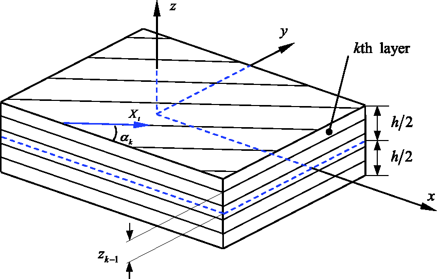
A piezoelectric laminated composite plate.
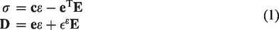
Considering the piezoelectric sensors and actuators, while retaining the orthotropic behavior of the fiber reinforced layer, the linear coupling between mechanical and electrical effects can be described by constitutive equations as follows
5
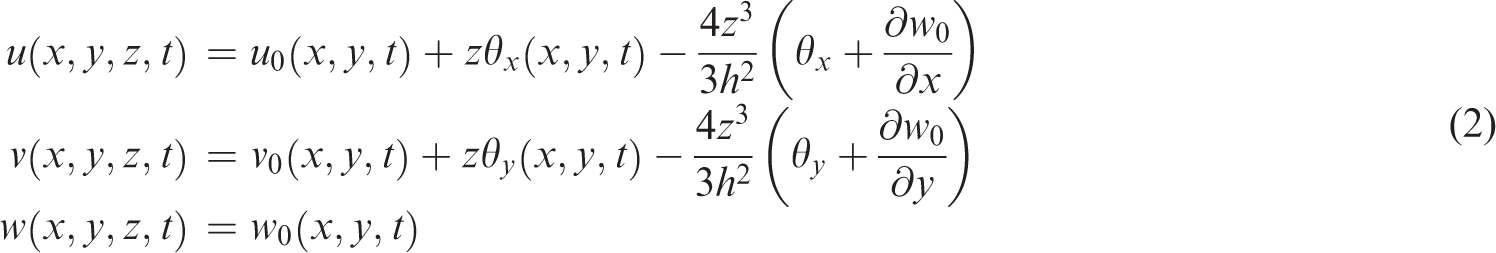
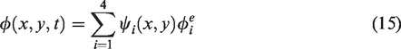
Approximations of displacements and electric potential
Using TSDT,
27
the displacement components of the laminated composite plate take the following form
We define


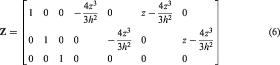
The infinitesimal strain components associated with the displacements are as follows

Supposing the

FE formulation
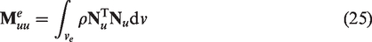
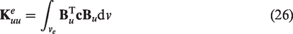
The nonconforming four-noded rectangular element is used to discretize the piezoelectric laminated plate. Each node has seven mechanical DOFs and one electrical potential DOF for each piezoelectric layer. The efficiency of this type of element for modeling of piezoelectric laminated structures has been demonstrated by Reddy.
27
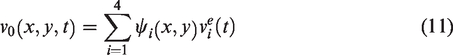
The continuous mechanical displacements


For each element, the nodal electric potential vector is


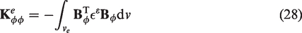
Substituting equations (10) to (14) into equation (5) yields

Substituting equation (19) into equation (7) yields


The electric field vector is the negative gradient of the electric potential

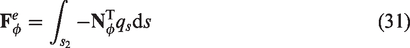
The Hamilton’s variational principle is adopted in the derivation of the elementary dynamic equation, which is as follows
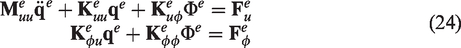


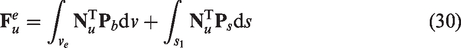


Considering equation (36), equation (32) can be written as

System realization and model reduction
Identification of system Markov parameters
System identification techniques are widely employed for developing a mathematical model by given experimental data. The electromechanical coupling FE model of piezoelectric smart structures provides time histories of the output signals of piezoelectric sensors; therefore, FE simulations using equation (37) are analogous to performing experimental investigations where the only direct outputs are time histories. Consequently, a system identification technique is a logical choice to set up a SSM for control law design. In this study, a system identification technique known as OKID28,29 technique is employed. The OKID method is formulated entirely in the time domain and is capable of handling general response data. In the following we will summarize it in brief.
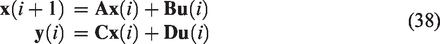
Supposing the FE model of a piezoelectric smart structure described by equation (37) can also be represented by the set of first-order difference equations of the form

The matrix

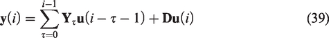
The input–output description of the system in equation (42) is

Equation (43) becomes

Note that equation (44) is in linear form thus the unknown observer parameter vector
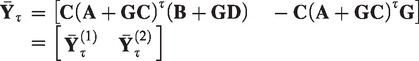
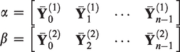
Juang et al.28,29 presented a complete description for the computation of the Markov parameters.
Minimal state-space realization
The ERA method
28
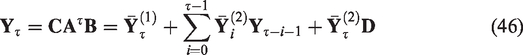
uses the system Markov parameters to construct Hankel matrices and then obtain the minimal SSM by singular value decomposition. The algorithm begins by forming the
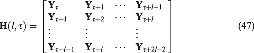
The order of the system is determined from the singular value decomposition of


The direct influence matrix
It is well known that the rank of the Hankel matrix is the order of the system. For noise-free data, the minimum order realization can be easily obtained by keeping only the nonzero Hankel singular values. However, for real data or data contaminated by noise, the Hankel matrix tends to be full rank, thus making the problem of determining a minimal SSM nontrivial. A criterion deciding which singular values are sufficiently small is very problem dependent. But in all investigated cases there always exists a significant drop in singular values for an increasing position index that signals the order of the system.
Vibration control in FE environment
An optimal controller
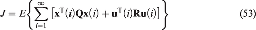
In optimal control the feedback control system is designed to minimize the cost function or performance index. A discrete-time minimal realization of the piezoelectric smart structure is represented by


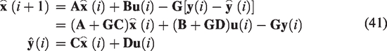
In the state feedback design, it is assumed that all of the state variables are available for feedback. However, this is not always the case and only the system outputs are available for feedback. Thus, one should design a suitable state estimator for the purpose of estimating the states of the system. Among several proposed observers, a state estimator based on the Kalman filter is selected in this study. The dynamic behavior of the Kalman filter is already given by equation (41) and the observer gain matrix
The selection of


Control-oriented FE simulation
The overall methodology for integration of a LQR controller into a FE code will be illustrated briefly. The process begins with performing an open-loop FE simulation with prescribed actuator inputs to obtain a set of corresponding output time histories. Band-limited white noise is preferred to be used as the input signal since it satisfies the condition of persistent excitation, as required by a reliable identification. The next step is to employ OKID method and ERA method, using the time histories of inputs and outputs obtained previously, to determine a discrete linear state-space system for use as a control law design model. Next, the LQR controller gain matrix
The major modification to the FE code is the updating of the actuator voltages at each time instant in the transient analysis to account for the feedback control. First, the sensor signals are calculated at a given time instant based on equations (36) and (37) and the system states are then estimated using equation (41). And then, the feedback voltages are determined based on equation (54). This process will continue for the predefined time duration of the computed response. Through the results of transient analysis, the control law can be evaluated in the FE environment. If the controller performance is not satisfactory, the controller can be redesigned and evaluated again until the desired performance is obtained.
Case studies and discussion
Validation of numerical code
A simple benchmark problem is solved to validate the numerical code. The results obtained using the developed code are compared with the published results. In this case, a bimorph cantilever piezoelectric plate, which consists of two uniaxially bonded PVDF layers with opposite polarities (see Figure 2) is considered. The length and width of the laminate are 100 and 5 mm, respectively, and the thickness of each lamina is 0.5 mm. The material properties of the PVDF are shown in Table 1. The cantilever plate is modeled with 10 identical plate elements, and each element has the dimension of 10 mm × 5 mm × 1 mm. The cantilever boundary conditions are simulated by specifying zero displacement DOF for the x, y, and z directions at the fixed end of the plate. With a unit voltage applied across the thickness, the deflection of the bimorph plate is calculated by the present FE model and compared with those proposed by Tzou and Ye.
30
To begin with, static analysis is performed to calculate the static deflection of the bimorph plate. For static analysis, equation (37) takes the form

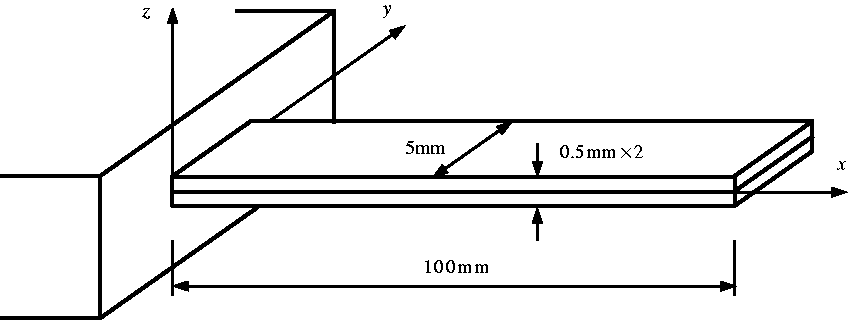
A cantilevered bimorph PVDF plate.
Material properties.
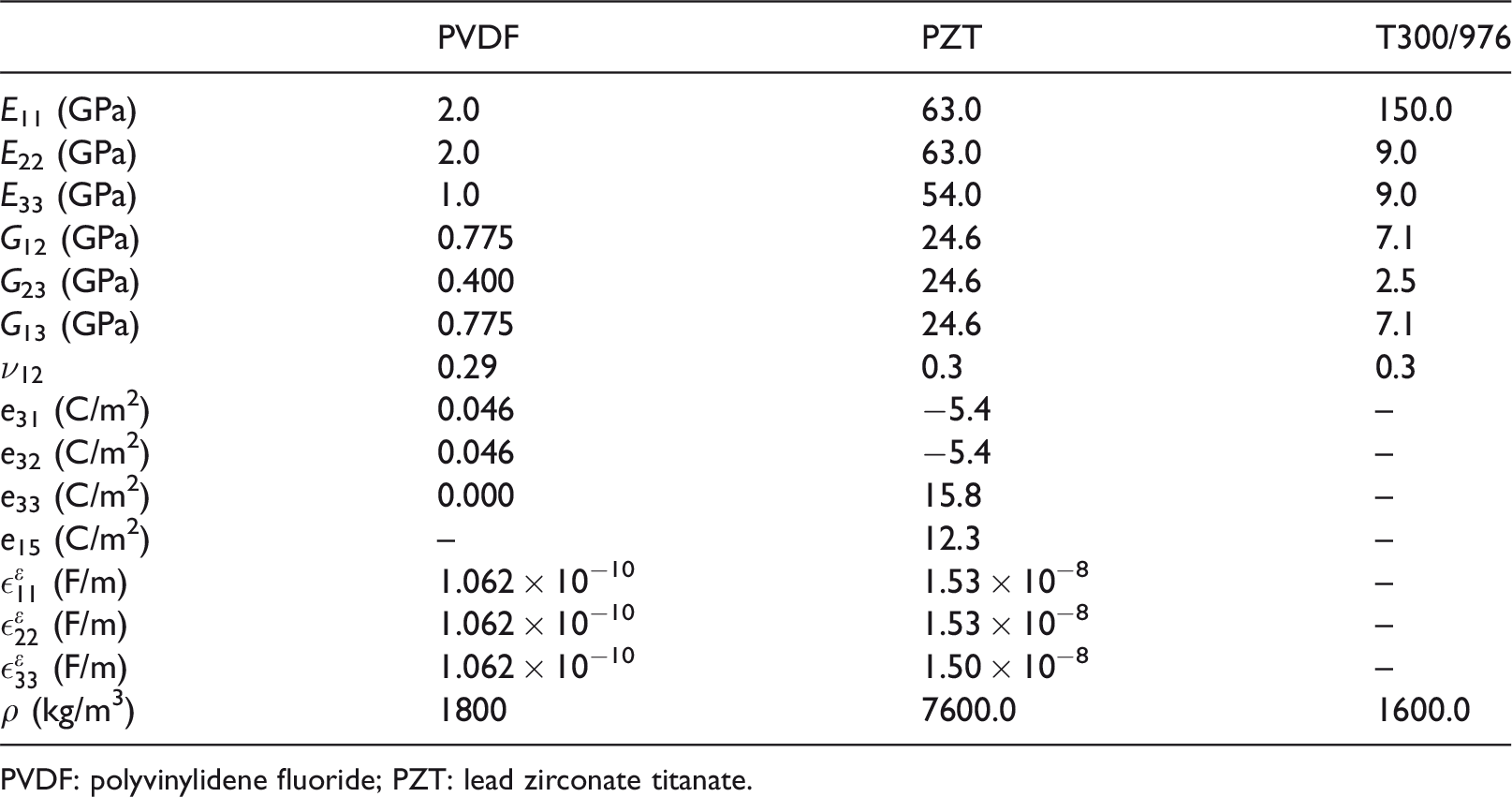
PVDF: polyvinylidene fluoride; PZT: lead zirconate titanate.
The results obtained by numerical solution of equation (59) are compared with the theoretical and other FE predictions as shown in Figure 3. It can be seen that the present results are much closer to the theoretical solutions than those from the solid FE results of Tzou and Ye,
30
since the solid FE model is relatively rigid and less efficient for thin plates due to the higher stiffness coefficients in the thickness direction. Furthermore, transient analysis is performed to verify the consistency between the steady-state value of the transient response and the static displacement. A time step
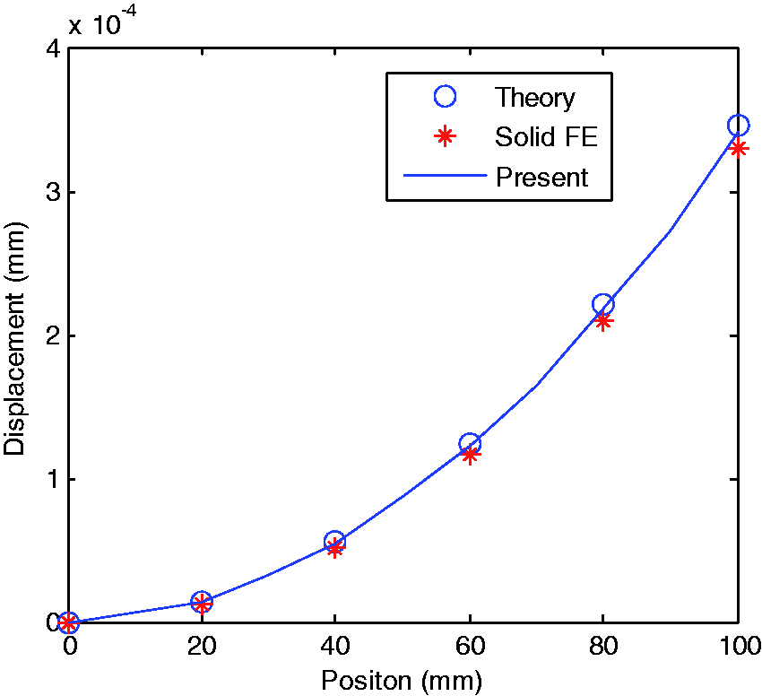
Static deflection of the bimorph plate for 1 V across the thickness. FE: finite element.
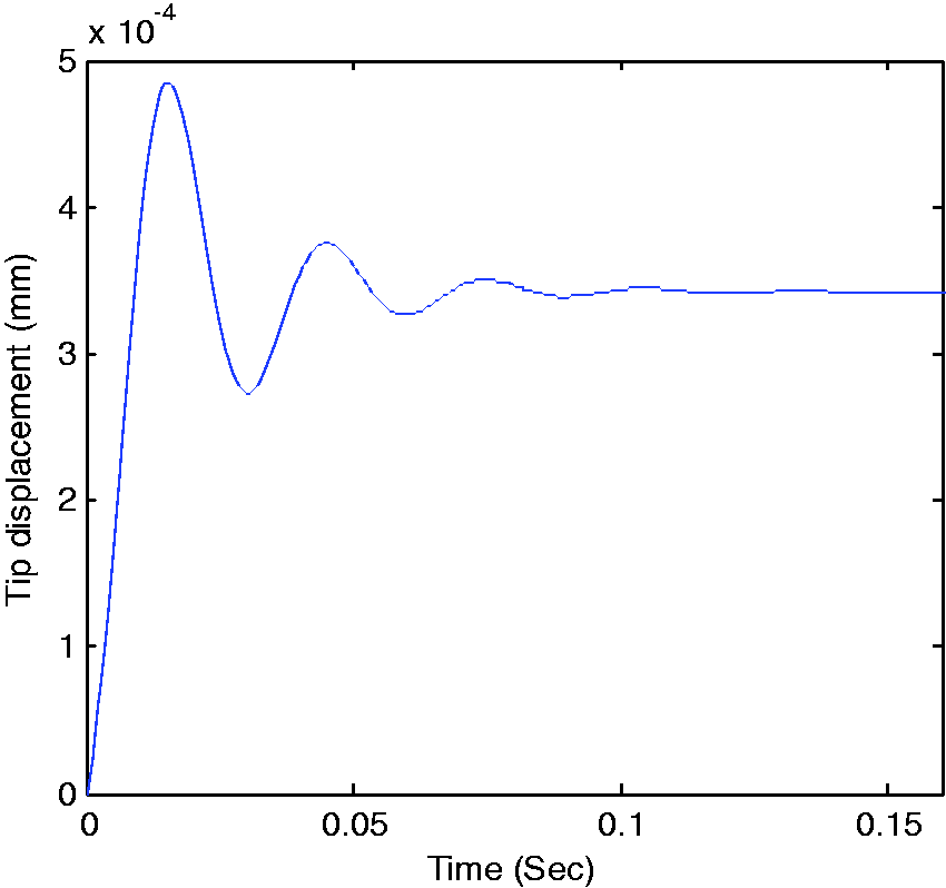
Transient response of the tip displacement with constant voltage applied.
Vibration control in FE environment
Having validated the FE code, we begin our discussion on controller design and active vibration control of a piezoelectric smart structure in FE environment. A simply supported square laminated composite plate with four collocated pairs of PZT S/As bonded on the top and bottom surfaces of the plate, as shown in Figure 5, is considered. The plate with side dimension
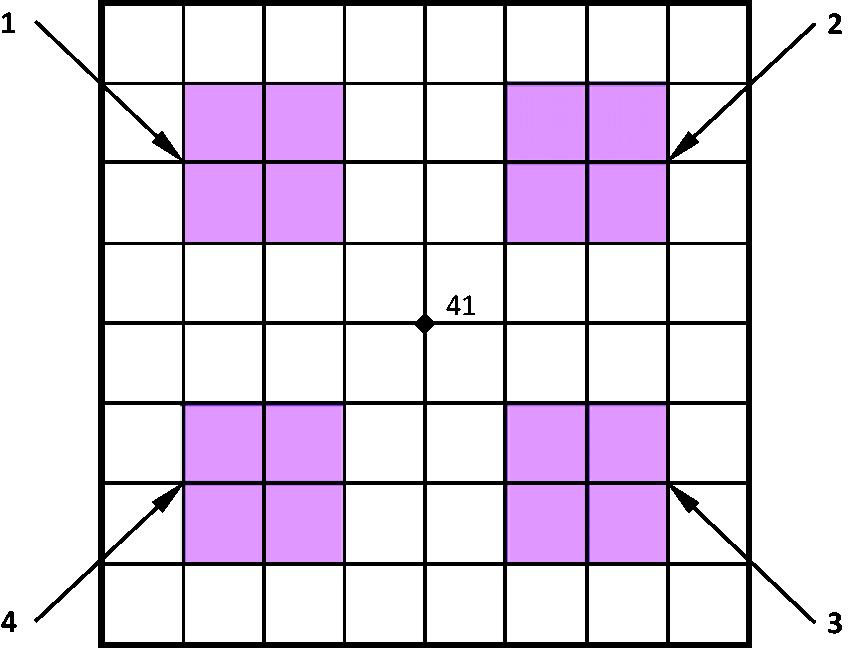
A simply supported laminated plate with four pairs of S/A.
White noise signals, band limited in a frequency range varying from 2 to 200 Hz, which cover six low-frequency modes of the plate, are applied to the four PZT actuators as input data, and the corresponding voltage output data of the four PZT sensors are obtained by performing open-loop FE analysis. The sampling rate of the input–output time is set to 400 Hz for system identification. The prementioned identification technique, i.e. OKID method, is employed to determine the system Markov parameters from the input–output data. For brevity, only the system Markov parameters observed at sensor 4 are shown in Figure 6. It can be seen from Figure 6 that the dynamic characteristics of the structure can be described by the obtained system Markov parameters. The ERA method is then used to find a state-space realization from the system Markov parameters. The order of the SSM is determined upon inspecting the singular values of the corresponding Hankel matrix. Figure 7 shows the singular values of the Hankel matrix. One can clearly observe that there are 12 first-order modes in the data, as evidenced by the sharp drop after the 12th singular value, and the fact that the rest of the singular values are numerical zeros. Hence, a MIMO SSM with the system order 12 is obtained from singular value decomposition of the Hankel matrix. The identified model can be utilized in the controller design procedure.
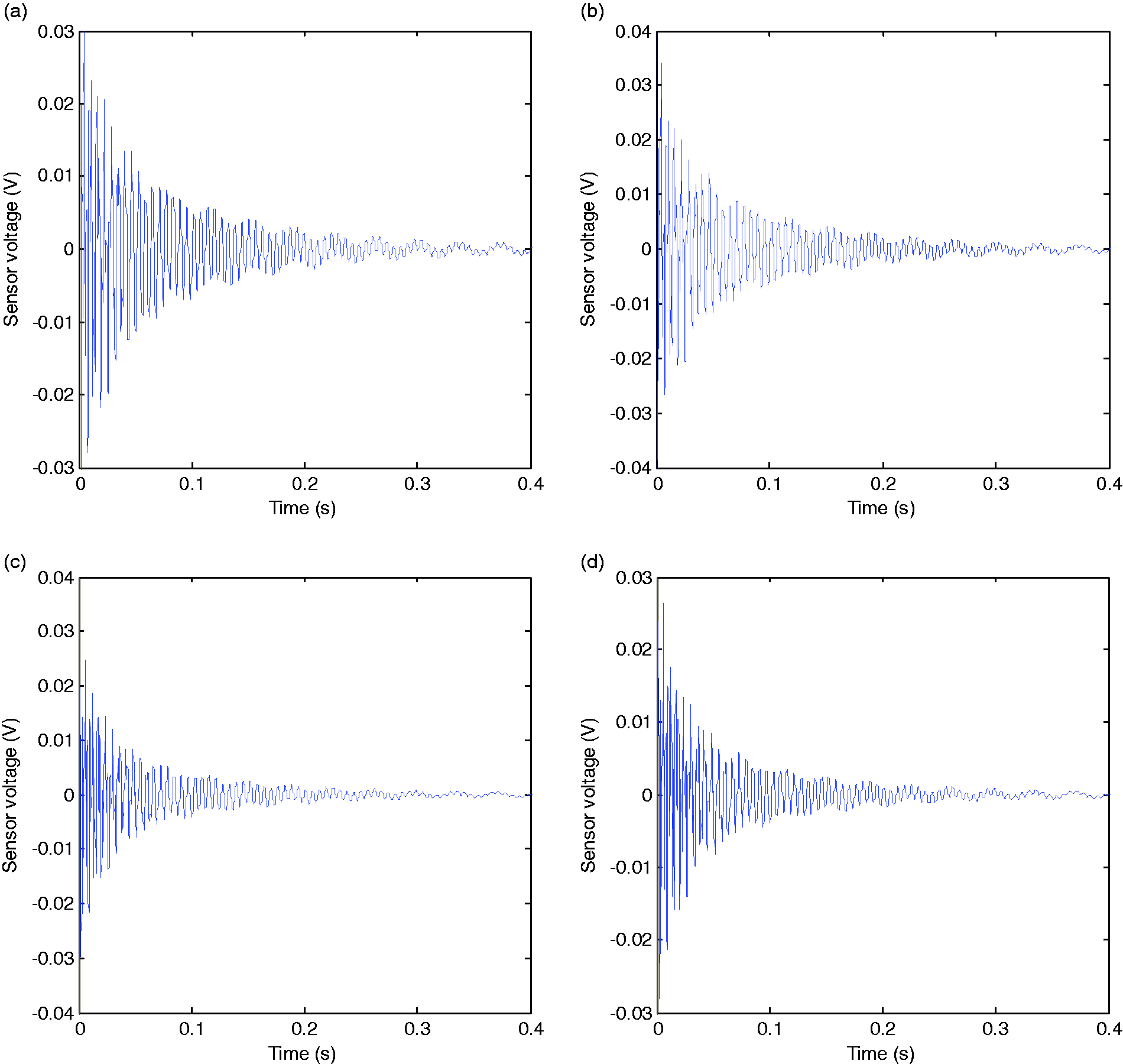
System Markov parameters observed at sensor 4: (a) stimulated by actuator 1, (b) stimulated by actuator 2, (a) stimulated by actuator 3, and (a) stimulated by actuator 4.
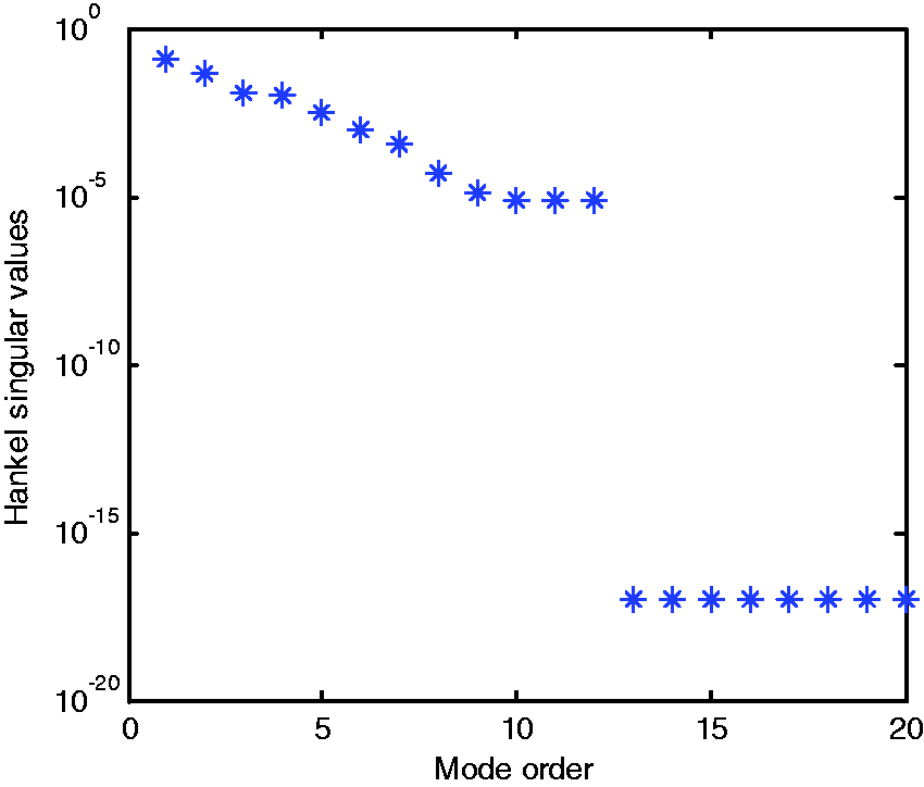
Singular values of the Hankel matrix.
After several attempts we set the parameter
Two cases are considered in vibration control of the simply supported square laminated plate. For case 1, the plate is initially exposed to a uniform distributed load of
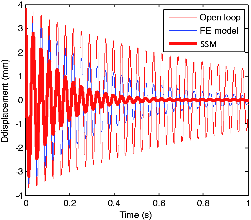
Transverse displacement of node 41 under initial disturbance. FE: finite element; SSM: state-space model.
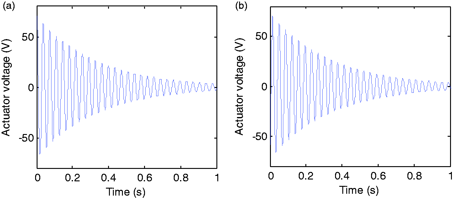
Actuator voltages for case 1: (a) actuator 1 and (b) actuator 2.
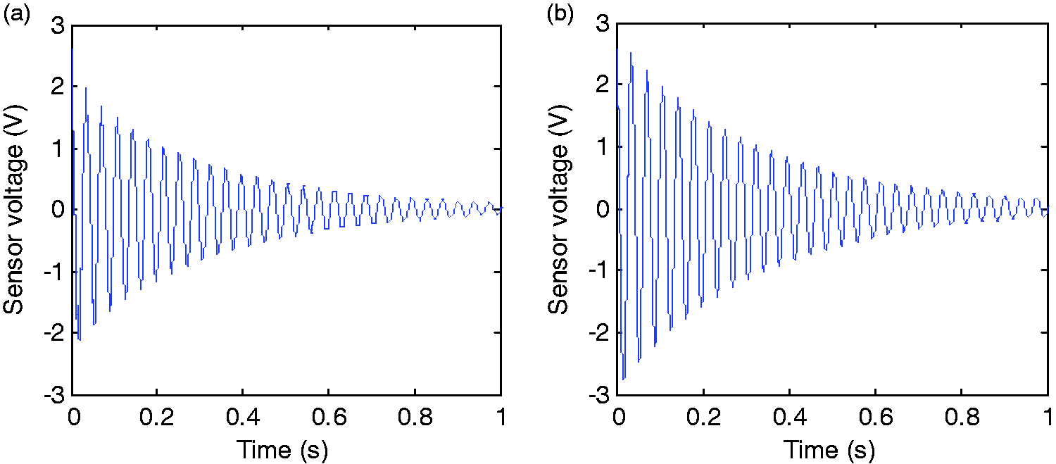
Sensor voltages for case 1: (a) sensor 1 and (b) sensor 2.
For case 2, a distributed transverse harmonic force
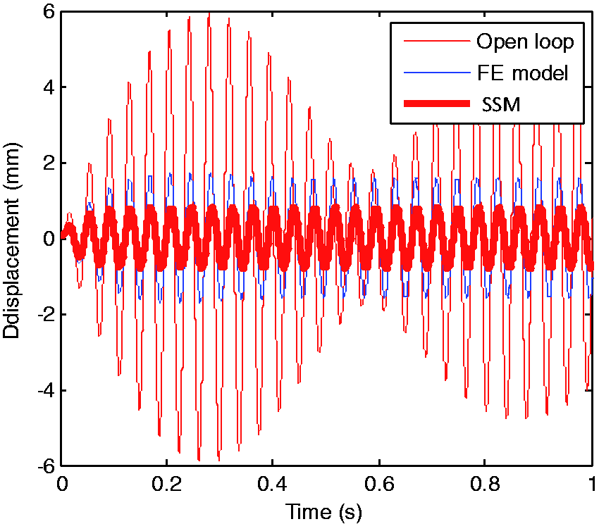
Transverse displacement of node 41 under harmonic load. FE: finite element; SSM: state-space model.
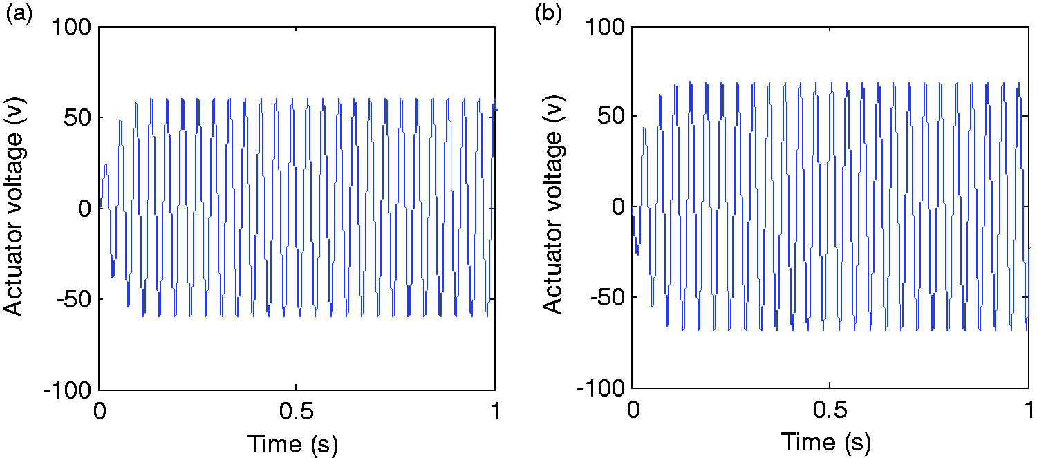
Actuator voltages for case 2: (a) actuator 1 and (b) actuator 2.
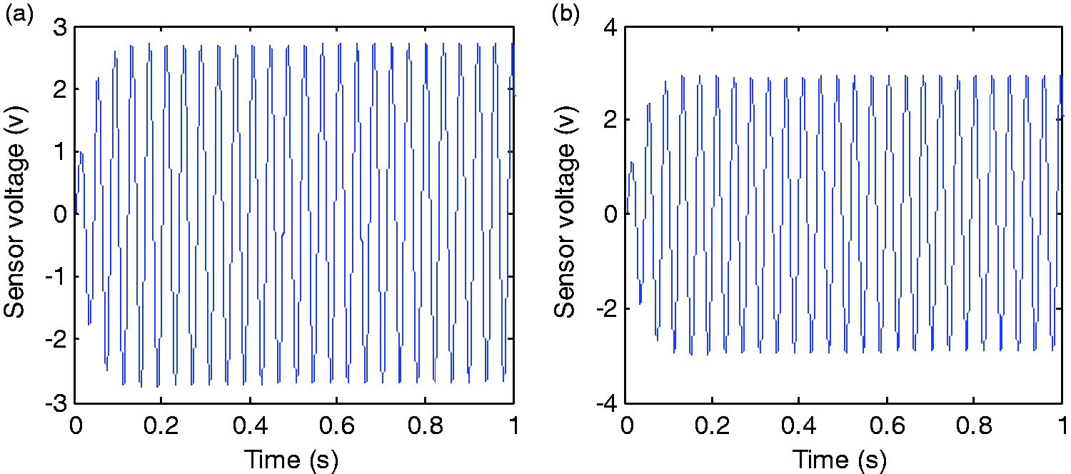
Sensor voltages for case 2: (a) sensor 1 and (b) sensor 2.
Generally, the SSM contains only the low-frequency modes. The high-frequency modes which are not included in the SSM are termed as unmodeled dynamics. Compared with SSM, it is generally considered that the FE model contains the unmodeled dynamics. Therefore, when the SSM-based controller operates in closed loop with FE model, the unmodeled dynamics are to be excited. In this way, the controller–structure interactions can then be captured numerically. Usually, we feed back the SSM-based controller outputs to the SSM to evaluate the controller performance. However, one can infer from Figures 8 and 11 that the performances of the same controller observed in SSM and in FE model are not the same due to unmodeled dynamics. That is to say, it is not adequate to evaluate the controller performance in SSM environment. Furthermore, it cannot be concluded that a SSM-based controller satisfying the control requirements still works well when it is connected to the real plant.
Conclusions
An active vibration controller is integrated into the FE model of a piezoelectric laminated plate to conduct vibration control simulations, with a focus on taking the controller–structure interactions into consideration. By using TSDT, an accurate open-loop FE model is developed and a system identification technique known as OKID approach together with ERA method is employed to obtain a reduced-order SSM. An optimal feedback controller is designed based on SSM and then integrated into the FE code by updating the actuator voltages at each time instant in the transient analysis. By this way the controller outputs are eventually fed back to the FE model, but not the SSM as in some traditional active vibration control methods. Because the FE model represents the real system much better than a SSM, the proposed FE model-based closed-loop simulations can be used to capture the controller structure interaction. Numerical examples are presented to demonstrate the efficiency of the proposed scheme in the simulation of an actively controlled piezoelectric structure. It is numerically demonstrated that there is no prior guarantee that a SSM-based controller satisfying the control requirements still works well in closed loop with the FE model due to unmodeled dynamics. It is strongly recommended to evaluate the performance of an active vibration controller by using FE model-based closed-loop simulations but not SSM-based closed-loop simulations. Future research calls for investigating unwanted controller–structure interactions occurring due to unmodeled dynamics, such as control spillover, based on the proposed method.
Footnotes
Declaration of conflicting interests
The author(s) declared no potential conflicts of interest with respect to the research, authorship, and/or publication of this article.
Funding
The author(s) disclosed receipt of the following financial support for the research, authorship, and/or publication of this article: This work was supported by the National Natural Science Foundation of China (No. 11572189).