
Abstract
Active hybrid aerodynamic and aerostatic bearing system has gradually become more valued in recent years for its application in the precision machine field, especially for precision instruments and mechanisms that require high rotational speed, high precision, and high rigidity support. In this system, air lubricated bearing is mainly used for support. Although the carrying capacity is not as high as oil film bearings, air lubricated bearings can provide a work environment where the rotor (spindle) will not experience axial deformation at high rotational speed and low heat generation. In practice, spindle system dynamic problems include critical speed, spindle imbalance, and improper bearing design, which can cause the spindle system to produce aperiodic motion, instability, and even chaotic motion under certain parameters and conditions during its operation. If severe, these irregular motions may cause machine damage or delay production. In order to understand what type of work situation can produce aperiodic phenomenon, and to prevent irregular vibration and reduce instantaneous air hammer effect, the finite difference method and mixed method are used to explore the related characteristics for spindle system. Meanwhile, relevant theories including bifurcation diagram, Poincare map, spectrum response phenomenon, and maximum Lyapunov exponents are applied to analyze rotor non-linear dynamic behavior. In addition, we verified the non-linear motion parameter conditions to prevent spindle system from falling into the instable status during design. The objective is to lower the probability of chaotic phenomenon in the system and reduce damage caused by irregular vibrations in the system. The result of this study can serve as a reference when designing precision spindle systems or mechanisms.
Keywords
Introduction
Active hybrid aerodynamic and aerostatic bearing (AHAAB) system is different than general bearing system. The rotation speed of general rotors (spindle) is only between 14,000 and 24,000 r/min, and has a DmN value (the spindle high-speed indicator, which is related to bearing material, structure design, carrying capacity, precision, and critical speed) upper limit of 2 × 10⁶. However, the spindle rotational speed of AHAAB can reach more than 3 × 10⁵ r/min and a DmN value greater than 2 × 10⁶. This is mainly because gas bearing has no contact; therefore, has very little friction. The bearing is almost operating in a no friction status. Thus, there is little wear between the rotor and the bearing, which results in longer spindle system life.1,2 Gas is also compressible, has very low value of viscosity, which means it has very little fluid shear and does not require much power to achieve very high rotation speed. This means that the bearing does not heat up easily, and can operate in a high temperature environment without affecting its dynamic performance. Because the lubricant used by this type of spindle system is air, it can also operate at extremely high rotation speed, high temperature, or low temperature. The homogenizing effect of gas can effectively compensate for processing deviation on the working surface and also significantly improve the rotational and translation accuracy of spindle system. Thus, gas bearing can serve as a circularity reference, straight line reference, and as a main machine component for ultra-precision processing technology and micro-processing technology. As such, it has received the attention of domestic and international academic fields and industries. The production and manufacturing standard of gas bearings represent the research level of humans in the ultra-precision machining technology field. Currently, air lubricated bearings have replaced large number of traditional rolling component or liquid film lubricated bearings in instruments and equipment that require high precision axis positioning, high rotational speed, low friction, and have other special environmental requirements. 3
Studies on the performance of bearing and rotor (spindle) related dynamic characteristics of air lubricated spindle system show that the static and dynamic characteristics of high-speed rotor (spindle) directly affect the precision quality of the work piece. Therefore, when designing an spindle system, not only does the torsion or bending strength of the spindle must be calculated, but the static and dynamic stiffness should also be carefully designed. In air lubricated bearing studies, how to accurately calculate air film pressure distribution has always been an important topic in analyzing air lubricated bearings. In 1991, Nguyen4,5 proposed using finite element method (FEM) to solve complex border gas bearing pressure distribution problems. The AHAAB used for this study have both externally supplied pressure and special groove or floating ring designs that provided superior support and stability. However, there are few studies conducted on this subject. For groove basic theory, scholars have used FEM to solve the pressure distribution of herringbone groove bearing and studied the effects produced by groove design. This includes stability analysis, pressure distribution, and the impact of critical parameters on the system. Study results showed that spindle systems with grooves can achieve superior stability.6–8 For air lubricated bearings with externally supplied pressure, holes setup above the bearing can provide appropriate gas pressure and also produce greater rigidity. Consequently, the rotor (spindle) can operate at a higher rotation speed.9,10 The aforementioned reference shows that the air film dynamic characteristics has a significant impact on the overall bearing support system, especially for the air film pressure, stiffness, and damping effect. In 1974, Bently 11 discovered that rotor-bearing system has 2nd order and 3rd order subharmonic vibration by experiments. Choi and Noah 12 proved that rotor-bearing system has subharmonic vibrations by numerical simulation. Although these references conducted studies on oil film bearing, very few studies were conducted on the rotor behavior of air lubricated bearing systems.
For the analysis methods of nonlinear behaviors, a new method called the Exp-function method was first proposed by He and Wu 13 and was successfully applied to a KdV equation with variable coefficients 14 and to high-dimensional nonlinear evolution equations. This method was also applied to obtain generalized solitary solutions of the generalized Drinfel’d–Sokolov–Wilson (DSW) system. Then, some of the solitary solutions are converted to periodic solutions or hyperbolic function solutions by a simple transformation. The research results show that the Exp-function method is a powerful and convenient mathematical tool for solving nonlinear evolution equations with higher order nonlinearity. 15 In 2003, a new perturbation method was proposed and can analyze the rotor dynamic equation efficiently. In contrast to the traditional perturbation methods, this technique does not require a small parameter for the rotor equation. According to the homotopy technique, a homotopy with an imbedding parameter is considered and replaced the small parameter, so this method can be called the homotopy perturbation method. 16 In 2008, He 17 proposed He’s frequency formulation for analyzing the nonlinear oscillators and also presented the application of variational principle.18–20 In 2017, He studied the well-known Hamilton’s principle and found that it is valid for the conditions prescribed at the beginning and at the end of the motion. 21 For AHAAB system, the initial position of rotor is known and can be applied the Hamilton’s principle to obtain the orbits caused by external forces and different operation conditions.
In recent years, Wang et al.22–25 used mixed method to solve the air film pressure distribution of high-speed rotor air lubricated bearing with grooves. Meanwhile, the system state trajectories, Poincaré maps, power spectra, bifurcation diagrams and Lyapunov exponents were used to analyze the dynamic behavior of the rotor and journal centers. In this study, we discovered that under different operation conditions, the rotor and journal centers have periodic, quasi-periodic, subharmonic or nonperiodic motions. It is also found that within a specific operating interval, the system may even produce chaotic motion.
System modeling and research method
Dynamic analysis of active hybrid aerodynamic and aerostatic bearing system
In AHAAB system, the interior of air lubricated bearings often have excess gas capacity (GC), and this GC generally has lower natural frequency. When certain interference source appears inside the system, and its frequency comes close to the natural frequency of the bearing systems, excitation will occur, causing resonance in the excess GC. This phenomenon is similar to air hammer striking an object, and is called air hammer vibration phenomenon. This phenomenon often causes bearing damage and rotor instability. The main reasons of air hammer are as follows:
Internal GC of a certain size: If the bearing’s total internal GC is Existence of an excitation source: Air hammer vibration is a self-excited vibration meaning an oscillation that occurs from the system’s internal excitation by internal gas pressure or volume changes. Thus, regardless of whether the system is static or rotating, or whether the pressure is normal or high pressure, air hammer still occurs. When the external interference frequency and internal excitation frequency is closed, a resonance phenomenon can be triggered. The distribution of air film pressure: The bearing’s internal pressure is determined by externally supplied pressure and bearing rotation speed. The higher the internal pressure, the more severe the air hammer vibration. When the rotation speed of rotor is closed or equal to the system GC’s vibration frequency, the air hammer can be exacerbated. The air hammer vibration always exists at critical rotation speed.
To overcome and consider the aforementioned three factors, we analyzed the pure air guided type of AHAAB systems and described below.
Pure air guided type bearing mainly utilizes air guided method shown in Figure 1, as well as integrated bearing surface groove design. This bearing type is divided into single-way valve forward and reverse air guided type, all groove air guided type, and partial groove air guided type. Because this type of system has the advantage of both static pressure and dynamic pressure bearings, it can effectively inhibit air hammer effect and improve system stability.
Pure air guided type bearing (a) with a single way valve, (b) with continued grooves and (c) with partial grooves.
This study mainly analyzes groove air guided bearing system. This spindle system has both dynamic and static pressure effects, and its dynamic pressure effects come from the groove design on the bearing surface. The static pressure effects come from the configuration of the air (Ps) from air guide holes. When analyzing the air film pressure distribution (P), designers must consider the Reynolds equation (1), as follows:

And also be satisfied periodic condition equation (3):
Numerical method was used to calculate the pressure distribution of the air film. Integration was conducted on lubrication area to obtain the relative carrying capacity:
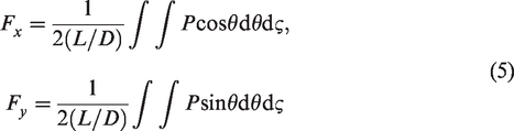
The air film total carrying capacity W is

To analyze the dynamic parameter of the air lubricated bearing system, the rotor mass is considered as mr and supported in the gas bearing. At the same time, the bearing is fixed on a rigid base. In the transient state, the equations of motion of O2 (i.e. the rotor center) and O3 (i.e. the journal center) can be written in Cartesian coordinates as:


The main advantage of the air guided type mixed dynamic/static pressure air lubricated bearing system is its high-speed stability, which is superior to general air film bearing. Thus relevant coefficients in equations (7) and (8) can be applied to confirm the stability of the AHAAB system. The motion behavior of rotor bearing system was also analyzed by the system state trajectories, Poincaré maps, power spectra, bifurcation diagrams and maximum Lyapunov exponents.
Proposed numerical method
In order to solve the Reynolds equation efficiently, we used two different numerical methods to analyze the bearing system, including traditional finite difference method (FDM) and proposed mixed method. These two sets of numerical results by different methods were confirmed and compared. The proposed mixed method mainly combines differential transformation method (DTM) and FDM. First, DTM was used to discretize time in the non-linear Reynolds equation. FDM central differential processing was used on position coordinates. The following describes the DTM in detail:
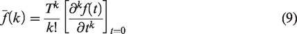
The differential transformation of the function of f(t) is defined as:
This method also requires confirmation of accuracy during calculation. That is, when time increases to the second interval, then the following equations (11) and (12) shall be used for accuracy calculation.
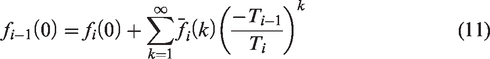
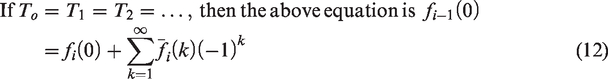
If the calculated value on the two sides of equation in equation (11) and (12) is too different, that means the accuracy was insufficient, and the time interval T must be reduced and the calculation redone.
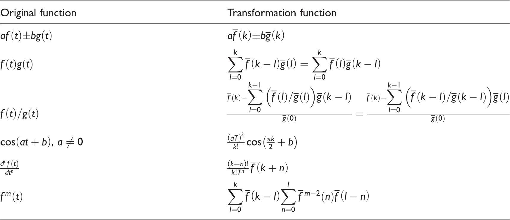
The differential transformation basic algorithm is as shown in Table 1.
Differential transformation basic calculation formula.
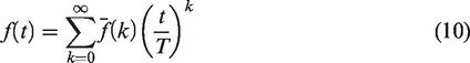
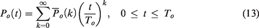
For AHAAB system, the pressure distribution function can then be calculated by differential transformation with boundary conditions. The pressure function is divided into n number of subintervals and each subinterval is divided into T0, T1, T2, T3, …, then equation (10) shall show the function in the first interval as:
If initial value 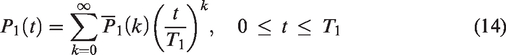
Using 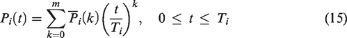
The aforementioned numerical method can be used with traditional perturbation method to conduct accuracy confirmation. This, combined with comparison of numerical results from follow-up experiments, can further verify the critical performance coefficient.
In solving the Reynolds equation for the current gas bearing system, the DTM is used for taking transformation with respect to the time domain τ, and hence equation (1) becomes
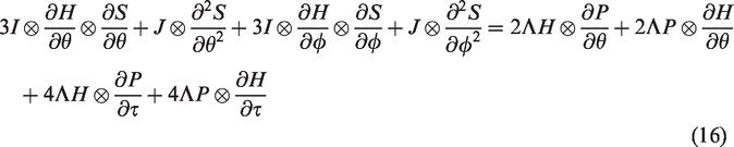
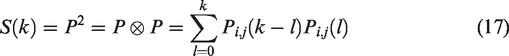
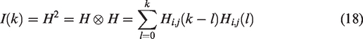

The FDM is then used to discretize (12) with respect to the θ and
Substituting (17) to (19) into (16) yields
From (20), Pi,j(k) is obtained for each time interval, where i and j are the coordinates of the node position and k indicates the kth term.
The motions of the rotor center are computed using an iterative procedure which commences by determining the acceleration and then computes the velocity and the displacement, on a step-by-step basis over time. In defining the initial conditions, the initial displacement (Xo,Yo) is specified as the static equilibrium position of the shaft and defines the gap Hi,j(k) between the shaft and the journal bearing, and the velocity of the rotor is assumed to be zero.
Calculation steps are as follows:
Step 1: When time
Step 2: Substitute the rotor center displacement obtained in step 1 into the rotor equilibrium equation to obtain the rotor center’s new displacement. As rotor changes the air film thickness H, the new displacement value forms the new H. Then substitute back the differential produced by the Reynolds equation to calculate the new pressure value.
Step 3: Use integration on pressure distribution obtained in step 2 which can produce new air film force, rigidity coefficient, and damping coefficient.
Step 4: Use the displacement and speed obtained in step 1, pressure distribution obtained in step 2, and air film force obtained in step 3 to form a new set of initial conditions. When time increases by
The aforementioned four steps can obtain the pressure distribution, air film thickness to position change correlation, change in air film support force, rigidity coefficient, damping coefficient, and rotor dynamic orbits with time increased. The maximum Lyapunov exponents are used as the main judgment criteria to predict periodic, quasi-periodic, aperiodic, and chaotic for different affecting factors such as bearing number, and rotor mass. High-speed air lubricated bearing’s rotation speed and rotor mass are used as the bifurcation parameter to construct the bifurcation diagram and analyze the dynamic stability of AHAAB system. We also analyzed the relationship between the maximum Lyapunov exponents and the key factors, as well as established the stable and unstable areas for different operating parameter of AHAAB system.
Result and discussion
Numerical analysis of bearing system
We used two different numerical methods to solve this bearing system for pure air guided type AHAAB system. Comparison shows that there is a difference in accuracy between the mixed method (DTM combined with FDM) and traditional FDM. Numerical test with different rotor mass at the same time step showed that the mixed method has superior accuracy of numerical simulation, and has good consistency with traditional FDM analysis results. Thus, the mixed method proposed in this study had superior convergence for this system. The comparison of rotor center orbits is shown in Tables 2 and 3.
Comparison of rotor center’s Poincare sectional value at different time interval τ and different rotor mass (results obtained with mixed method calculation).
Comparison of rotor center’s Poincare sectional value at different time interval τ and different bearing number (results obtained with mixed method calculation).
For mixed method stability numerical analysis, we tested the effects of different time intervals on values, as well as used Poincare sectional value to compare displacement changes under different operating conditions. Results are shown in Tables 2 and 3.
The numerical results show that the mixed method used in this study has superior convergence for AHAAB system and is more suitable for this system. The mixed method can effectively calculate the track of system regardless of rotor mass change or increase in bearing number. Tables 2 and 3 results show that time interval does not need to be overly meticulously to obtain sufficiently precise numerical results. Thus, for follow-up dynamic analysis, π/300 is used for the time interval calculation.
Rotor dynamic behavior analysis of AHAAB system
Effect of rotor mass on the system
The bearing number (rotation speed) is set to be Λ = 3.45, and rotor mass Phase diagram and dynamic trajectory diagram
Fig. 2(2.1(a) and (b), 2.2(a) and (b), … 2.12(a) and (b)) shows that the rotor center and journal center with less mass (
Phase diagram (2.1a to 2.12a), journal center dynamic track (2.1b to 2.12b), spectrum response of rotor center in the horizontal direction (2.1c to 2.12c), and in the vertical direction (2.1d to 2.12d) when the rotor mass at the rotor center is
b. Spectrum analysis
Fig. 2(2.1(c) and (d), 2.2(c) and (d), …, 2.12(c) and (d)) shows the dynamic effects of the rotor center at the horizontal and vertical directions. Study shows that when the rotor mass is at c. Bifurcation diagram
As shown in Figures 3 and 4, we used rotor mass
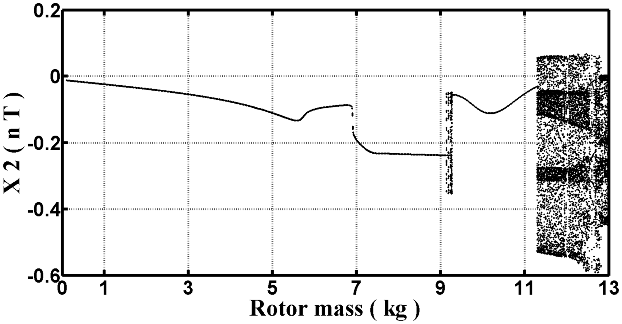
Bifurcation diagram when the rotor center in the horizontal direction X2(nT) with different rotor mass; system bearing number Λ = 3.45.
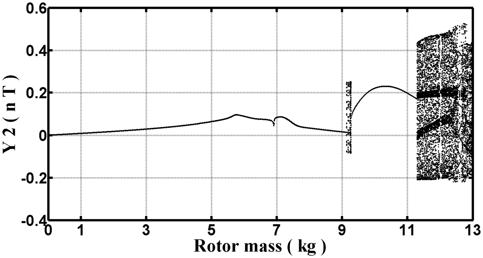
Bifurcation diagram of the rotor center in the vertical direction Y2(nT) with different rotor mass; system bearing number Λ = 3.45.
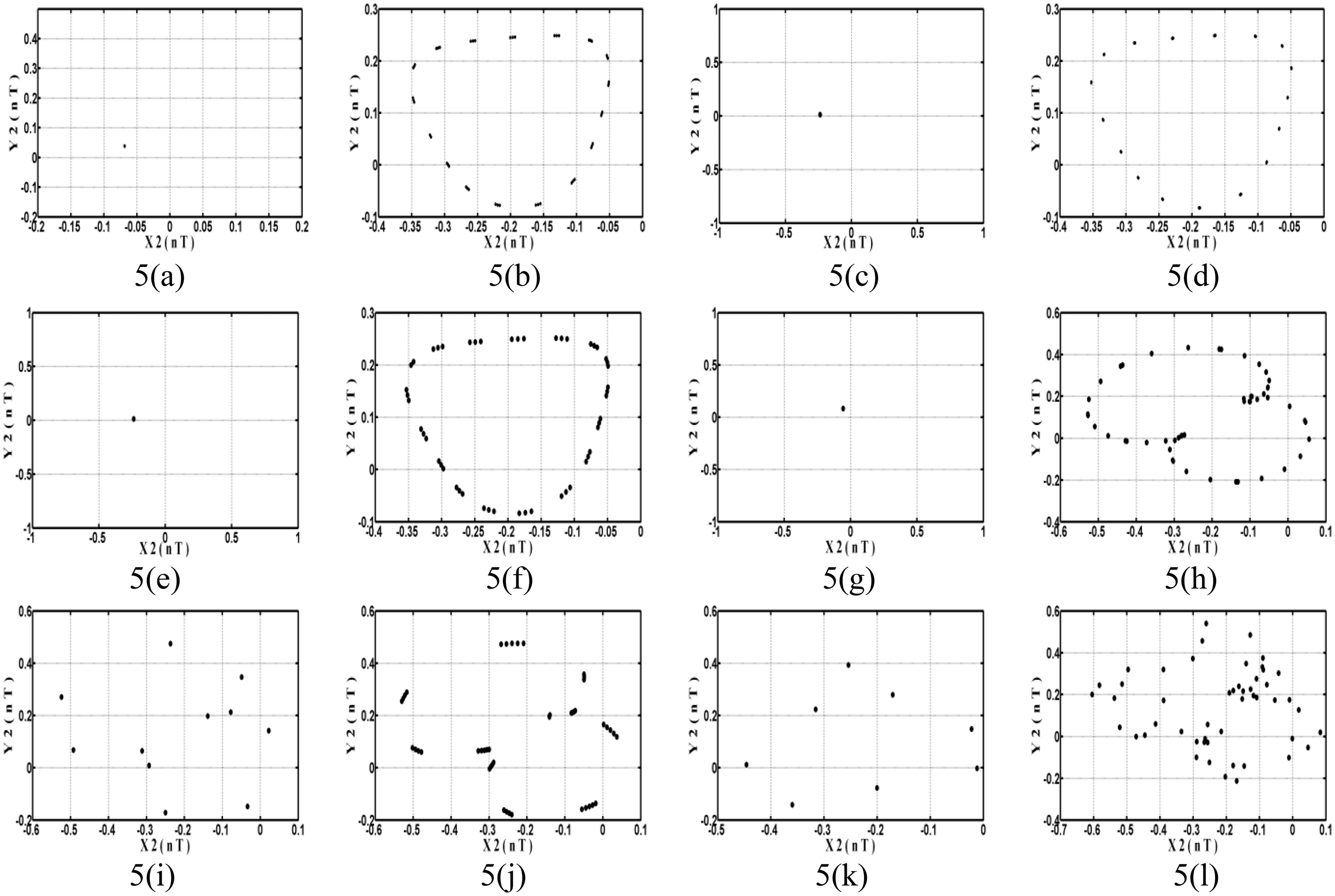
Poincare sectional diagram when the rotor is at different rotor mass (a)
When the mass increased to
Rotor center dynamic behavior for different rotor mass (system bearing number Λ = 3.45).
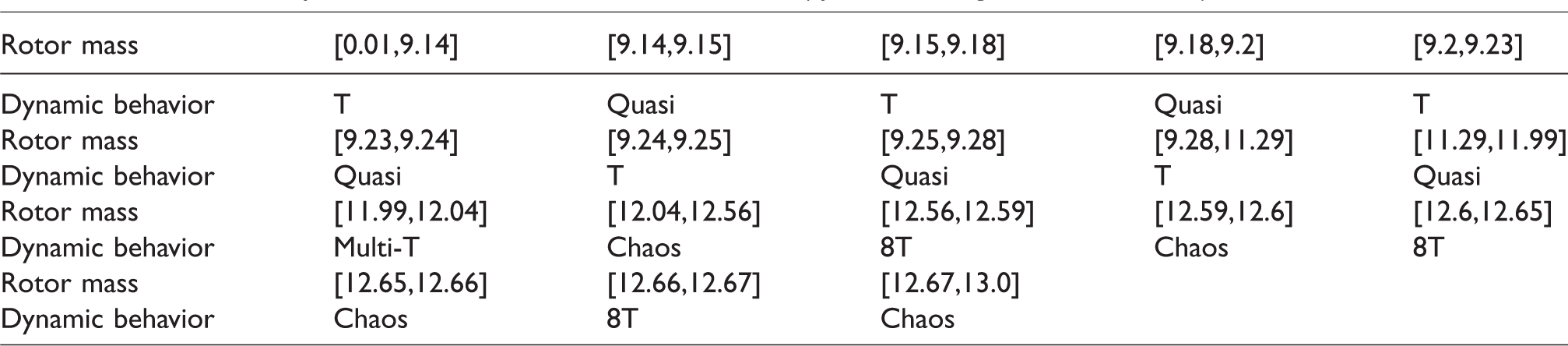
Figure 5 shows that when
To confirm chaotic behavior, we used maximum Lyapunov exponents for interpretation and further verification. Figure 6 shows that when the maximum Lyapunov exponent is close to zero, then the system is in non-chaotic behavior. When
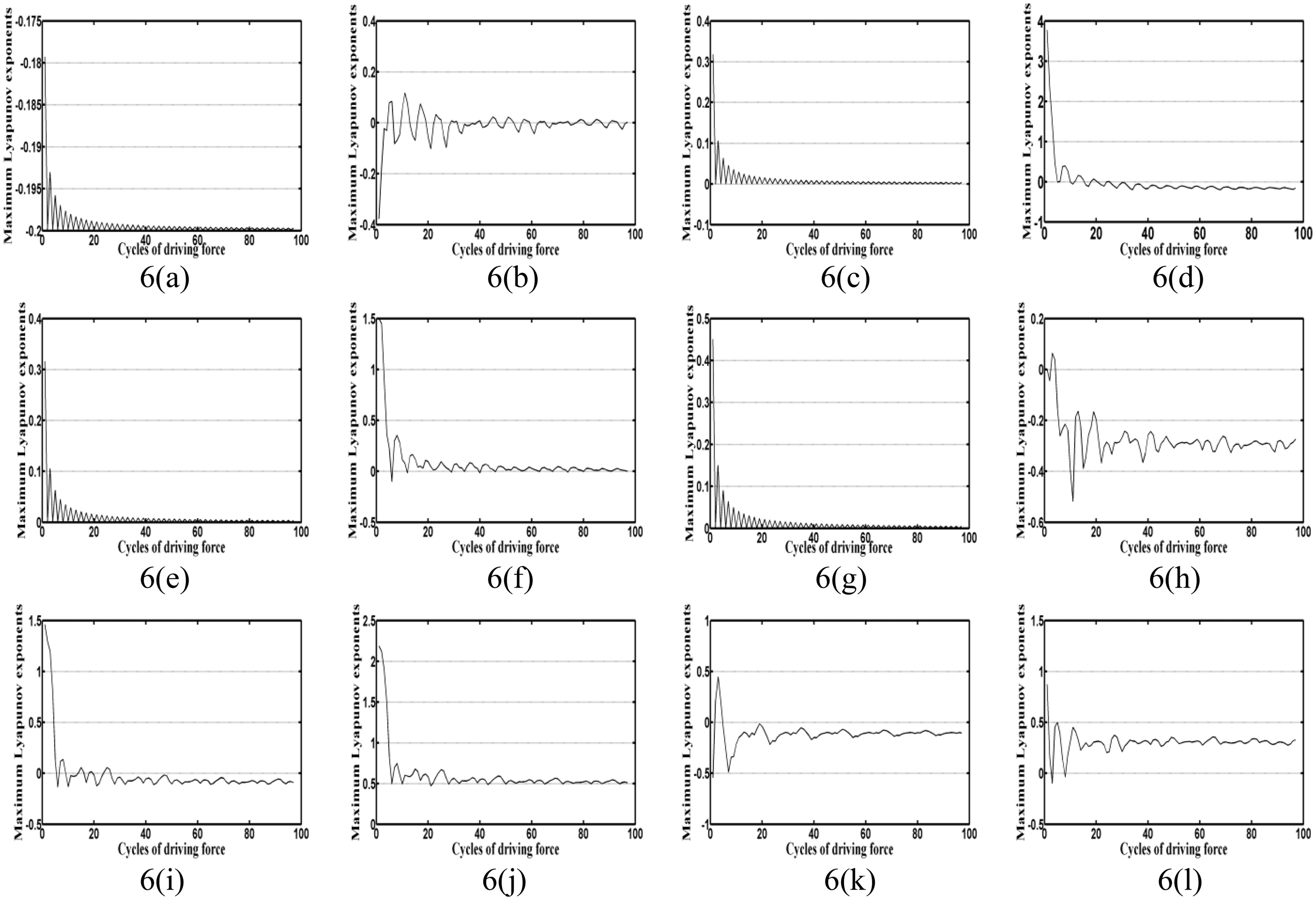
Maximum Lyapunov exponents of the rotor center at different rotor mass (a)
Effect of bearing number on the system
Because the rotational speed of rotor related to the bearing number, it affects the performance of the AHAAB system, the bearing number (Λ) is used as the bifurcation parameter and the rotor mass is set at mr=2.7 kg to analyze the system dynamic behavior:
Phase diagram and dynamic trajectory diagram
Figure 7(7.1(a) and (b), 7.2(a) and (b), …, 7.6(a) and (b)) shows that with smaller bearing number (Λ = 2.3, 4.5), the rotor exhibited regular behavior. When Λ was increased to 5.65, the system exhibited irregular motion. When bearing number reached 5.82, the dynamic orbit changed to regular motion. When Λ = 5.97 and 6.4, the rotor center’s behavior became more stable and regular.
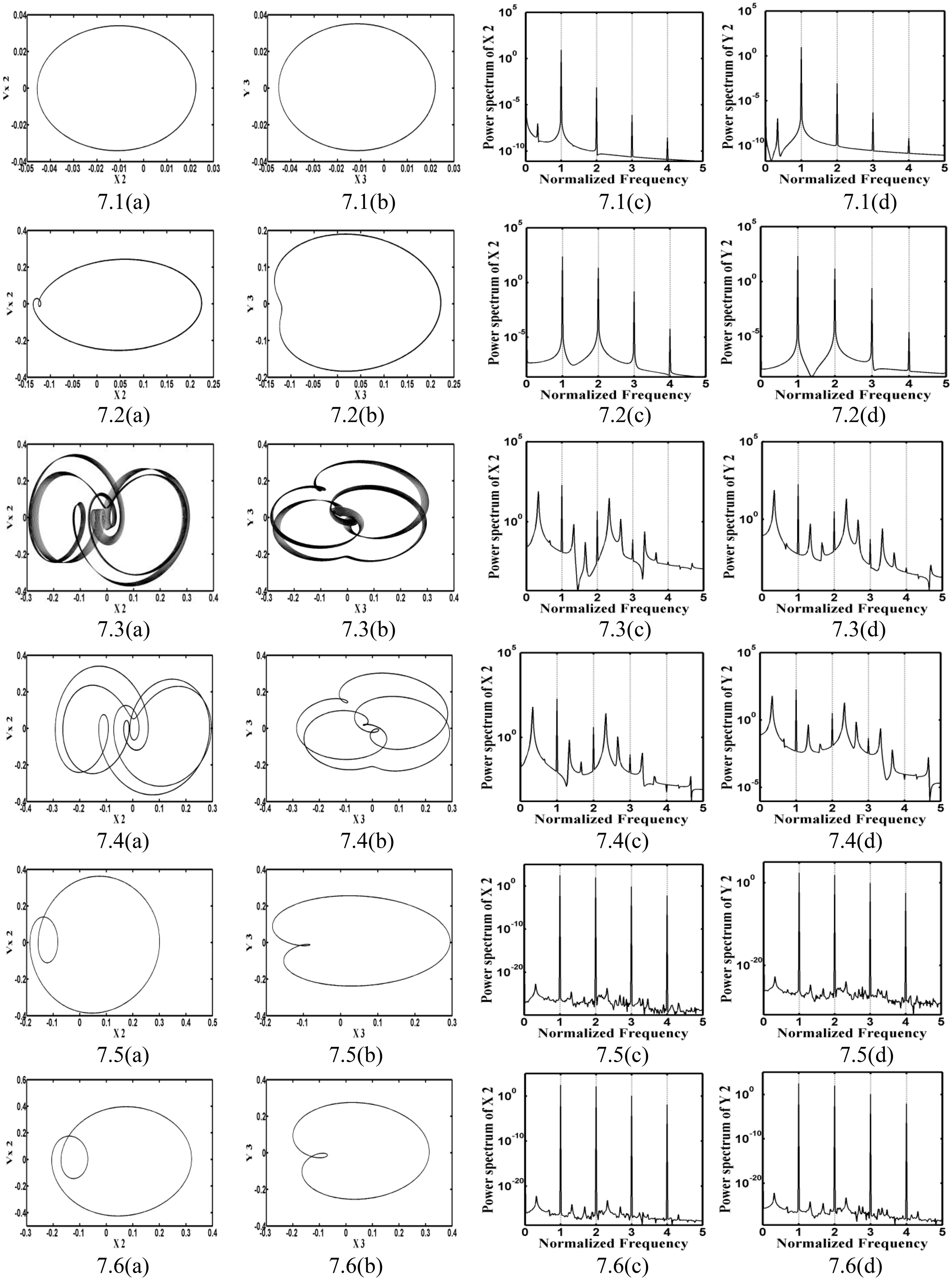
Phase diagram (7.1a to 7.6a), journal center dynamic trajectory diagram (7.1b to 7.6b), spectrum response of rotor center in the horizontal direction (7.1c to 7.6c), and in the vertical direction (7.1d to 7.6d) when the rotor center bearing number is Λ = 2.3, 4.5, 5.65, 5.82, 5.97, 6.4 (rotor mass set at mr=2.7 kg).
b. Spectrum analysis
Figure 7(7.1(c) and (d), 7.2(c) and (d), …, 7.6(c) and (d)) shows the dynamic effect of different bearing number on the rotor center in the horizontal and vertical directions. Results show that when the bearing number is at Λ = 2.3 and 4.5, the rotor center exhibits a T-periodic motion. When Λ = 5.65, spectrum response figure (Figure 7(7.3(c) and (d))) shows the rotor center of horizontal and vertical directions both has aperiodic and chaotic motion. As bearing number increased to Λ = 5.82, the motion changes to 3 T-periodic motion. At Λ = 5.97 and 6.4, the system changes to T-periodic motion. This is the same in both horizontal and vertical directions.
c. Bifurcation diagram
As shown in Figures 8 and 9, we used different bearing number Λ as the primary analysis parameter to explore the effect of different bearing number Λ on the system. At the same time, we set the bearing number between 1.0 and 7.0 for the actual operating condition. At low bearing number Λ = 2.3 and 4.5, the system rotor center shows T-periodic motion in both vertical and horizontal directions. This phenomenon is verified by Figure 10(a) and (b). When bearing number is increased to Λ = 5.65, system changes to chaotic motion. Figure 10(c) clearly shows that at this time, the system produced multiple uneven discrete points. This chaotic motion is maintained only when 5.65
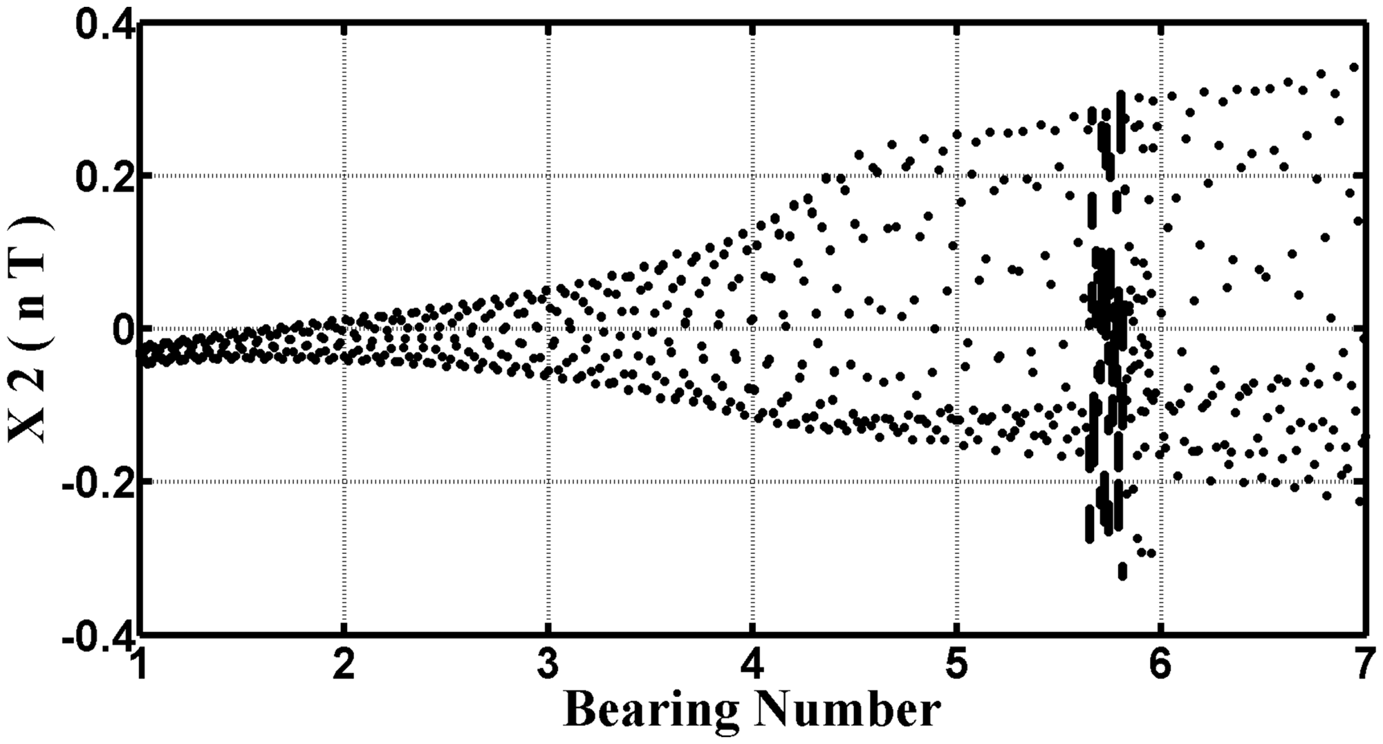
Bifurcation diagram when the rotor center in the horizontal direction X2(nT) with different bearing number; rotor mass set at mr=2.7 kg.
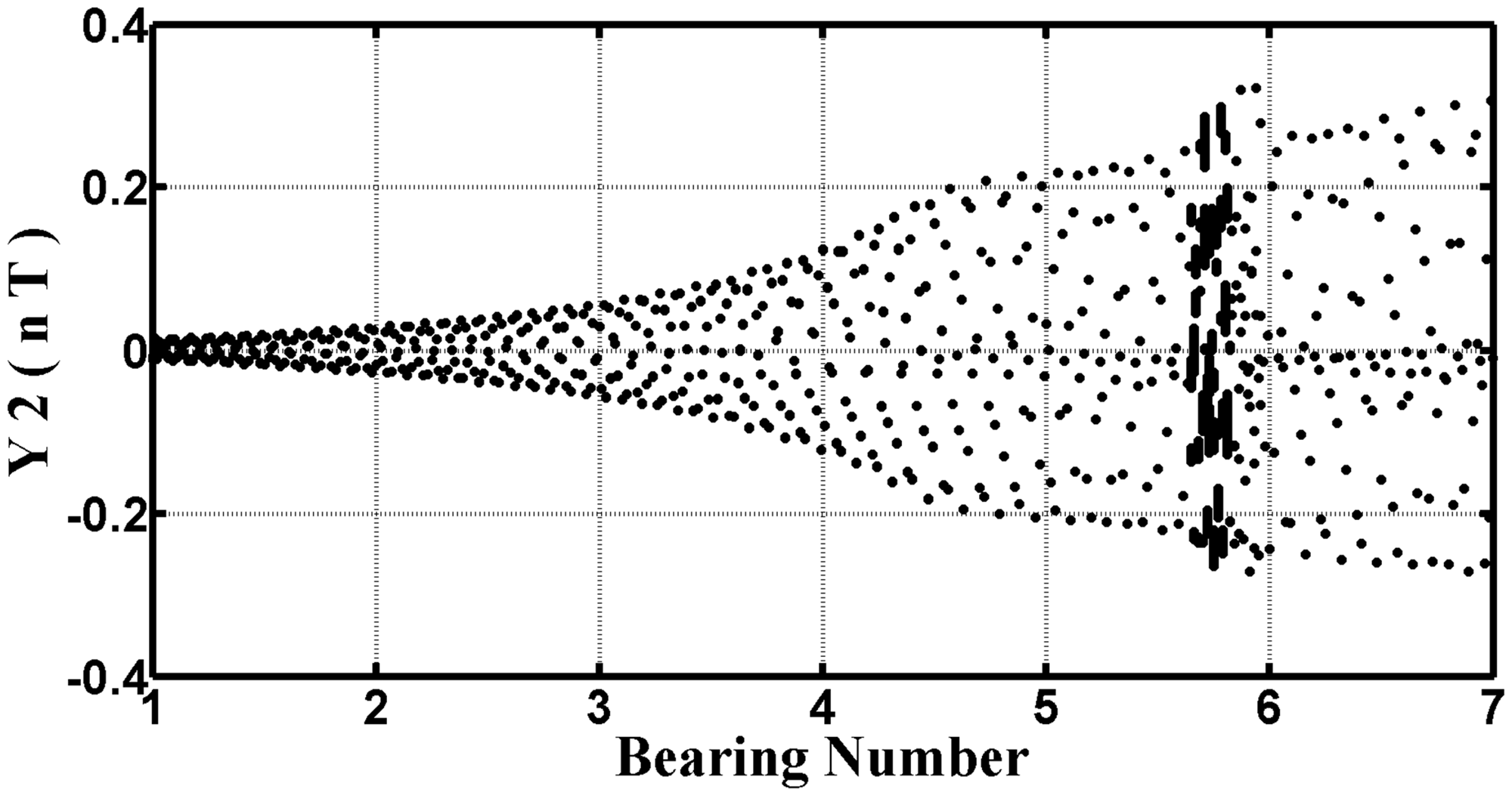
Bifurcation diagram when the rotor center in the vertical direction Y2(nT) with different bearing number; rotor mass set at mr=2.7 kg.
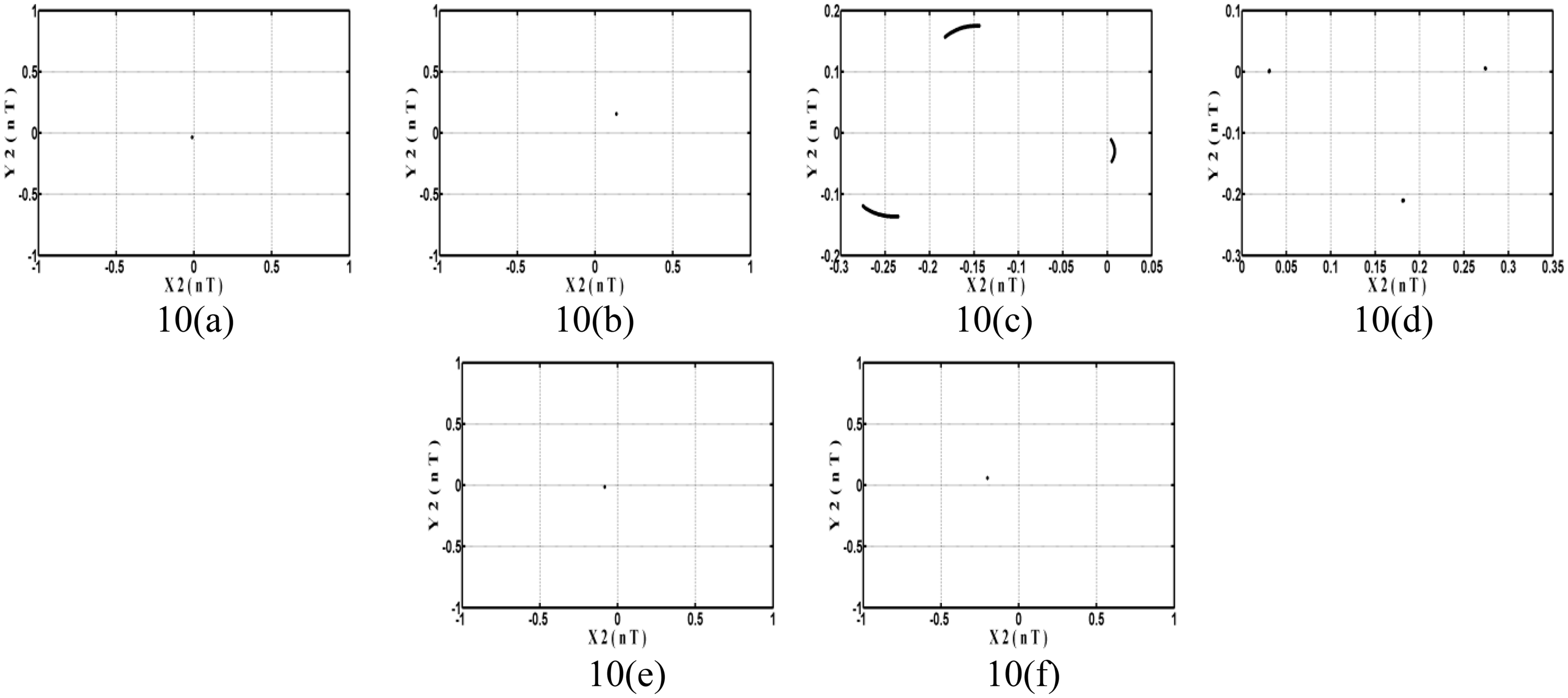
Poincare sectional diagram when the rotor center is at different bearing number (a) Λ = 2.3, (b) 4.5, (c) 5.65, (d) 5.82, (e) 5.97, and (f) 6.4 (rotor mass set at mr=2.7 kg).
The relationship between the rotor center’s motion and bearing number is very complex. Thus, we organized 1.0≤Λ ≤ 7.0 interval in Table 5, as shown.
Dynamic behavior of rotor center with different bearing number (1.0≤Λ ≤ 7.0, rotor mass set at mr=2.7 kg).

For chaotic behavior confirmation, we used maximum Lyapunov exponents for interpretation and verification. Figure 11 shows that when maximum Lyapunov exponents are less than zero, the system exhibits non-chaotic behavior. When Λ = 5.65 (as shown in Figure 11(c)), the index is greater than zero, and the system motion is in chaotic behavior.
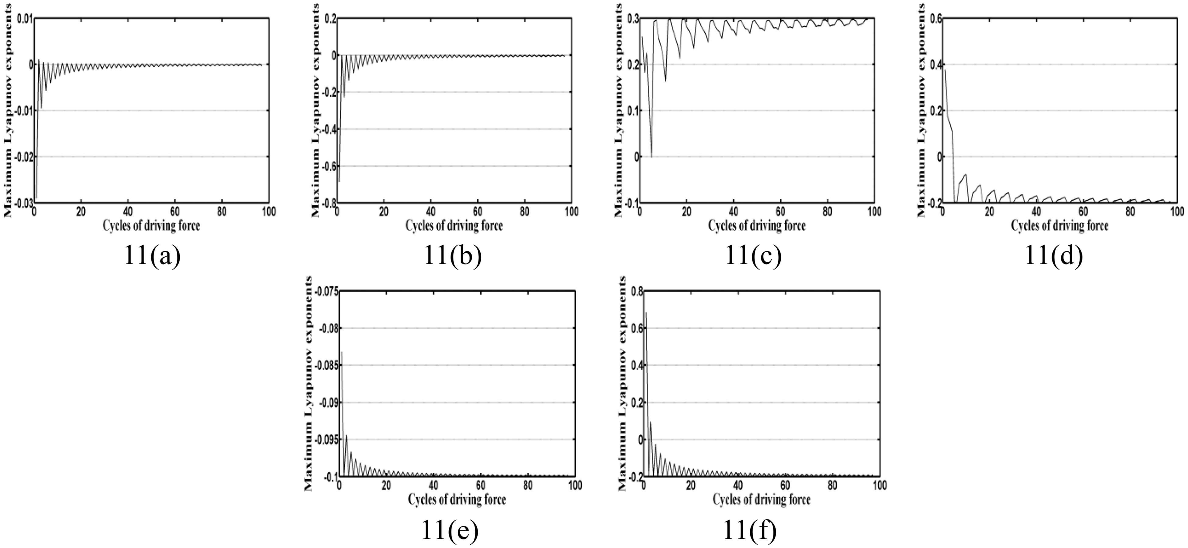
Maximum Lyapunov exponents of the rotor center at different bearing number (a) Λ = 2.3, (b) 4.5, (c) 5.65, (d) 5.82, (e) 5.97, and (f) 6.4 (rotor mass set at mr=2.7 kg).
Conclusions
This study has analyzed the dynamic behavior of an AHAAB system by utilizing a mixed numerical scheme comprising the DTM and the FDM. The system state trajectories, Poincaré maps, power spectra, bifurcation diagrams and Lyapunov exponents have revealed the presence of a complex dynamic behavior comprising periodic, sub-harmonic, quasi-periodic and chaotic responses of the rotor center. Meanwhile, the mixed method is the best candidate, and from Table 6 the results obtained by the FDM and DTM&FDM (mixed method) methods for the orbits of the rotor center prove that a good agreement exists between different sets of results. Moreover, the mixed method converges under all the considered conditions and therefore represents a more appropriate method for analyzing the nonlinear dynamic response of the AHAAB system. The results of this study provide an understanding of the nonlinear dynamic behavior of AHAAB systems characterized by different rotor masses and bearing numbers. Specifically, the results have shown that chaos appears in four rotor mass intervals, namely 12.04–12.56, 12.59–12.6, 12.65–12.66 and 12.67–13.0 kg. Regarding the influence of the bearing number on the dynamic response of the bearing system, the results have shown that the chaotic motion only occurs in the bearing number range of 5.65
Comparison of various numerical calculation results for pure air guided type bearing system rotor center displacement.
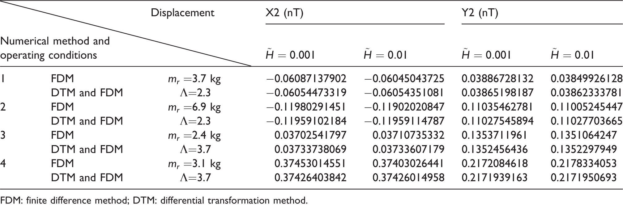
FDM: finite difference method; DTM: differential transformation method.
Footnotes
Declaration of conflicting interests
The author(s) declared no potential conflicts of interest with respect to the research, authorship, and/or publication of this article.
Funding
The author(s) disclosed receipt of the following financial support for the research, authorship, and/or publication of this article: The authors gratefully acknowledge the financial support provided to this study by the Ministry of Science and Technology of Taiwan under Grant Numbers MOST-106-2221-E-167-012-MY2 and MOST-106-2622-E-167-010-CC3, 107-2634-F-005 -001 and 106-2622-8-167-001-TE3.