
Abstract
In order to achieve the fast response of turboshaft engine combined with torsional vibration, a predictive controller of helicopter/engine based on the least mean square adaptive torsional vibration suppression is proposed and designed. First, in order to make up for the insufficiency of conventional notch filter on torsional vibration suppression with changeable frequency under variable rotor speed, an adaptive one based on least mean square is presented in the process of helicopter autorotation downward. Then, based on the least mean square adaptive filter, a predictive controller based on the support vector regression is proposed to compensate for the dynamic control performance in helicopter autorotation recovery process. It is shown that least mean square adaptive filter can suppress all low-order torsional vibrations with amplitude less than 15% in comparison with the notch filter, which proves the more remarkable ability of adaptive torsional vibration suppression. Meanwhile, the droop of power turbine speed can be reduced to less than 0.3% with the steady-state error no more than 0.01% by adopting the predictive controller based on least mean square adaptive torsional vibration suppression. The fast response and high-quality control of turboshaft engine has been realized.
Keywords
Introduction
Helicopter is a complex dynamics system with multi-degrees of freedom and strong coupling, whose torsional stability has always been a serious problem badly in need of being solved. 1 There is only one load channel from the engine to the rotor system, and any fault will pose a serious threat to flight safety. 2 Therefore, in terms of the structure and power, the torque transmission system of helicopter is a key component without redundant backup. 3
Since 1950s, turboshaft engine has become the core power device of rotorcraft because of its advantages of light weight, small volume, small vibration, and easy operation. Nevertheless, the speed feedback loop as the main loop aims at keeping engine output speed constant. In this case, when the output speed is fluctuating, the speed sensors feel these changes and adjust the fuel supply by the engine fuel-metering unit. If the speed fluctuates unexpectedly, the fuel is bound to response, both of which couple each other, causing the serious self-excited vibration. 4 Therefore, the torsional vibration is an unavoidable key problem in the design process of helicopter control system.
The torsional vibration modelling and control of helicopter/engine coupling system have been studied abroad earlier. Boeing and Sikorsky encountered torsional vibrations in 1960s and 1970s. 5 Wong introduced a simplified rotor drive train model to simulate the torsional vibration based on the linear model of turboshaft engine, which could simulate the dynamic characteristics of torsional vibration but could barely reflect the real working condition of the propulsion system. 1 In terms of control scheme, Hansford 6 proposed and utilized the impedance matching method to analyse the torsional vibration of the integrated helicopter system in 1998. A series of torsional vibration filters were proposed in the speed feedback loop of the power turbine to do the suppression after conducting an enormous amount of research on the rotor speed control based on the integrated helicopter/engine control platform. 7 The early torsional vibration filter is vibration damper and replaced by notch filter later.8–10 Unfortunately, the phase shift in low frequency of the general notch filter is too large, which will degrade the performance of computerized numerical control system. Li 11 proposed several notch filters in parallel combination. In this case, the control system can select different filter according to the working conditions of the engine. Therefore, the notch filters designed can not only effectively suppress the torsional vibration but also weaken the effect on the performance of the control system through introducing the additional phase of passband.
With the rapid development of rotorcraft and engine design technology, the technical bottleneck that restricts the implementation of variable rotor speed technology is gradually eliminated. The latest research shows that variable rotor speed aircraft and the integrated control can significantly improve the manoeuvrability and flexibility of rotorcraft, reduce noise, and decrease engine fuel consumption, whose benefits are obvious.12–15 The variable rotor speed control has become the inevitable development direction of rotorcraft in the future. However, as far as turboshaft engine is concerned, variable rotor speed has also brought two key problems: the rotor speed is no longer constant but variable in a large range, resulting in the corresponding variety of the equivalent damping and stiffness. Under these circumstances, the significant variation of torsional vibration fundamental frequency will occur, and the conventional constant notch filter designed at fixed frequency is no longer applicable. Therefore, in order to suppress the torsional vibration more efficaciously, it is necessary to propose and design a high-quality torsional vibration filter with adaptive capability.
The rotor demanded torque and engine output torque match each other through the clutches with variable transmission ratio in variable rotor speed, which enhances the coupling between the helicopter subsystem and the engine subsystem. For the conventional cascade Proportion-Integration-Differentiation (PID) controller, it is very difficult to obtain high-quality control effect.16–17 During helicopter manoeuvre flight, there exists assignable time-delay effect that is caused by the hysteretic rotor torque measurement and engine dynamic response, which must be taken into account within the small time scale. The cascade PID control method appears to lack of ability to forecast. On the contrary, the predictive controller tends to be accessible as an alternative to solve the problems of time-varying hysteretic nonlinear systems owing to its predictive potency. 18 Since the 1990s, the theory and application of linear predictive control have made great progress, 18 such as dynamic matrix control, generalized predictive control and so on, which can solve the optimization problems with constraints in real time. In recent years, some new forecasting methods have been proposed, such as robust model predictive control (MPC) 19 and nonlinear MPC, which can effectively solve the control problems of nonlinear systems with complex constraints and disturbances. Nevertheless, the above research has not yet been applied to the integrated control for helicopter/engine system based on torsional vibration suppression.
Therefore, in terms of the lack of research on predictive control of helicopter/engine based on adaptive torsional vibration suppression, first, the torsional vibration modes of rotor drive train system with two turboshaft engines are calculated by MATLAB and ANSYS separately. Second, based on UH-60A model, the integrated helicopter/engine model combined with torsional vibration is established. Third, the adaptive torsional vibration filter based on least mean square (LMS) is proposed and the simulation and verification of adaptive torsional vibration suppression are conducted in the process of helicopter autorotation downward. Finally, based on the LMS adaptive filter, a predictive controller is proposed by utilizing support vector regression (SVR). Meanwhile, several numerical simulations are carried out and compared with the predictive controller based on constant notch filter in the control effect.
Torsional vibration characteristic of rotor drive train system and torque transmission train model
The turboshaft engine assembled on a helicopter drives rotor and tail rotor through the transmission system consisting of power turbine, gearbox and transmission shaft, which form a rotor drive train system together. A typical schematic diagram of a simplified rotor drive train system is shown in Figure 1.
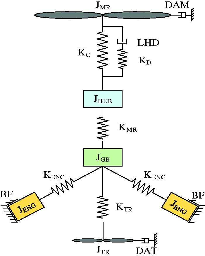
Schematic diagram showing rotor drive train system.
This simplified model is obtained through lumping rotational inertias and springs 20 from the detailed model of the drive train system. Two turboshaft engines are connected to a helicopter. Engines’ power turbine is connected to the rotor drive train through gears. JMR, JENG, JGB, JHUB and JTR represent the moment of inertia of main rotor, turbine shaft engine, gearbox, hub and tail rotor, respectively. KC, KD, KMR, KENG and KTR are the equivalent stiffness of rotor blade centrifugal force, blade lag spring, transmission shaft, engine output shaft and tail rotor transmission shaft, respectively. DAM, LHD, BF and DAT are main rotor’s aerodynamic damping, lag hinge damper, engine damping and tail rotor’s aerodynamic damping. Figure 2 shows the block diagram of Figure 1 by combining two engines together and neglecting the rotor hub inertia. KEQ represents equivalent shaft stiffness, and τ1 and τ2 are the time constant of lag-lead damper.
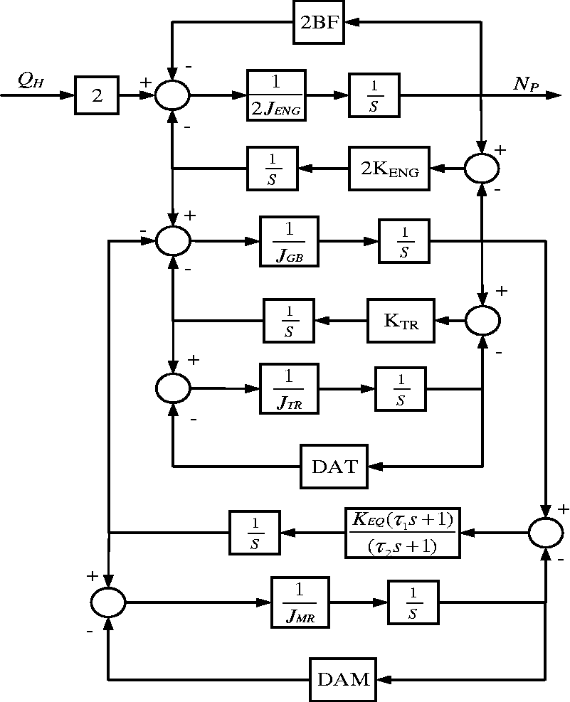
Block diagram showing rotor drive train.
As shown in Figure 2, the transfer function module is available in MATLAB/Simulink and the Bode diagram at the rotor speed of 27 rad/s is shown in Figure 3.
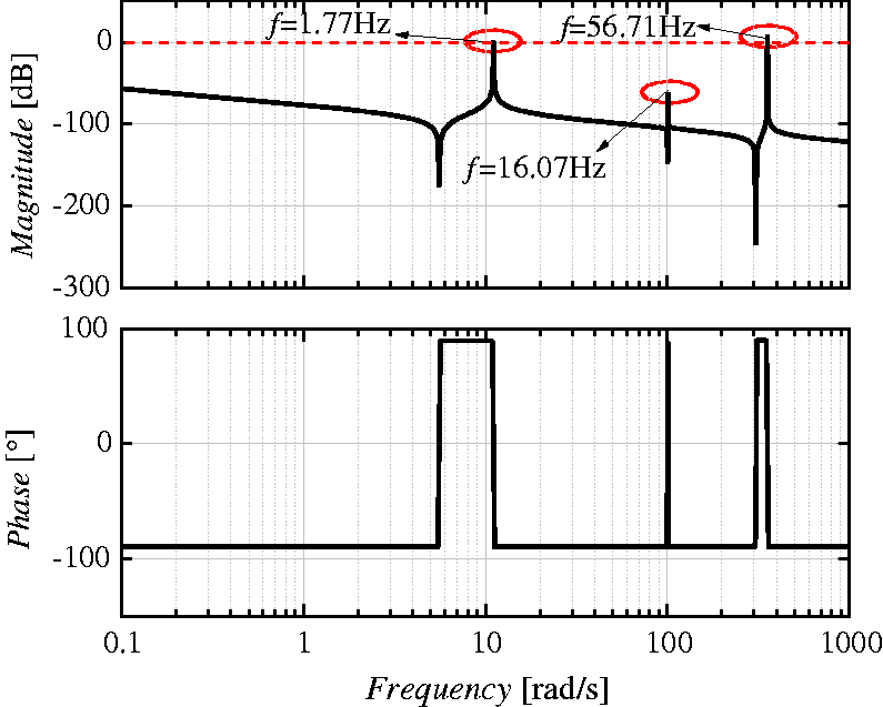
Bode plot of a general rotor drive train system.
Figure 3 shows the Bode plot of a typical rotor drive train system. There are three torsional vibration peaks corresponding to three vibration modes. The first frequency is produced by the main rotor to the combined engines and gearbox. The second mode is the vibration produced by the tail rotor to the rest of the system. The third one is the dynamics of engine to gearbox. The first torsional vibration frequency has a dominant influence on torsional instability because it has the lowest frequency and generally has the highest peak that is above 0 dB line. Therefore, it is necessary to design an appropriate filter, otherwise it will cause torsional vibration instability.
In order to verify the accuracy of the torsional vibration modes calculated by the model mentioned above, another numerical simulation is conducted through ANSYS at the same rotor speed. In the modal calculation of ANSYS, the stiffness and rotating inertia have a leading effect on the frequency of torsional vibration. Thus, all components of the rotor drive train system shown in Figure 1 can be simplified to be several particles with the moment of inertia, which are connected by relative spring and damper each other. The simplified rotor drive train system in ANSYS is shown in Figure 4, and the torsional vibration modes calculated by the two approaches are listed in Table 1.
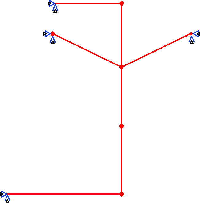
Simplified rotor drive train system in ANSYS.
Comparison table of torsional vibration modal calculation.
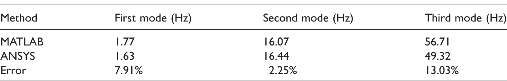
As presented in Table 1, except for the third mode, the errors of the first and second torsional vibration frequency calculated by two methods are both less than 10%, which verifies the accuracy of the rotor load transfer function model built by MATLAB.
In practical engineering, the modes of torsional vibration vary in different working conditions, which is called ‘dynamic frequency’. The model shown in Figure 2 takes into account the effect of centrifugal force on the blade stiffness, while there is a positive correlation between the centrifugal force and rotor speed. The frequency-amplitude curves of rotor drive train system under different rotor speed are shown in Figure 5.
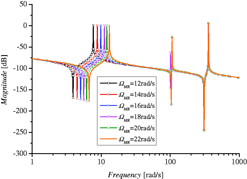
Frequency-amplitude curves of rotor drive train system at different rotor speed.
As shown in Figure 5, the second and third torsional vibration modes stay constant under different rotor speed. On the contrary, when the rotor speed increases from 24 rad/s to 29 rad/s, the fundamental frequency varies in the range of 1.22–2.09 Hz.
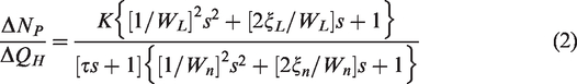
For simplicity, the lag-lead damped is taken out of Figure 2, where the torsional vibration mainly produced by main rotor and tail rotor, so the transfer function can be described in equation (1). Nevertheless, it is shown in Figure 5 that the second mode hardly changes under different rotor speed. Hence, a Harmonic signal with same frequency can be utilized to replace the second one. The simplified torque transmission train model is shown in equation (2)

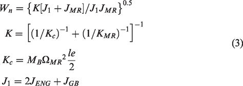
MB, l, and e represent the mass of blade, the length from blade hinge to blade tip and the distance from rotor centre to blade hinge, respectively.
The design of adaptive torsional vibration filter based on LMS and simulation verification
Based on UH-60A helicopter/engine model, the torque transmission train model shown in equation (2) is introduced, where the torsional vibration speed is added to the engine output speed linearly, which constitutes the integrated helicopter/engine model combined with torsional vibration. It can be seen from Figure 5 that the rotor speed has a significant effect on the low order torsional vibration of the system, and the nonlinear characteristics of the system are more obvious. In this case, in order to suppress the torsional vibration signal with frequency varying in a wide range, the conventional notch filter must be designed with wide bandwidth. However, the increase of the bandwidth will result in the decrease of amplitude attenuation gain, and the additional phase shift will rise with the increase of the attenuation gain. Thus, the notch filter with constant coefficient designed at single frequency will hardly be applicable. A high-quality torsional vibration filter with adaptive capability is urgently in need of being proposed.
LMS adaptive filter is significantly different from the conventional one, which is based on the estimation of statistical properties of the input and output signals. The filter can track the changes of the reference signal and adjust the coefficients with specific algorithm, which help the filter achieve the optimal effect. It can be not only continuous but also discrete. Discrete adaptive filter is composed of variable weight coefficient and automatic tuning coefficient. The output signals generated by the filter compare with the reference signal to obtain errors, which is available to adjust the parameters of the filter by LMS adaptive algorithm and to realize the LMS of errors. 21 The diagram of principle is shown in Figure 6.
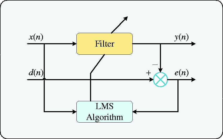
The structure of adaptive filter based on LMS.
LMS algorithm is the basic of adaptive filter, and it is a random recursive algorithm. 21 As shown in Figure 6, LMS adaptive filter is composed of filter and LMS algorithm, which constitute feedback loop. x(n) in Figure 6 represents the input signal, y(n) and d(n) represent the output signal and reference signal, and e(n) is the error of y(n) and d(n), which affects the weight coefficients of filter. The specific algorithms are as follows.
Supposing that x(n) and w(n) are sequences of M order, which are expressed as follows


The expressions of the output signal and the weight coefficient are


The error can be available as follows

The mean square of error is shown in equation (9)

According to the equation (9), the mean square of the error is only related to the weight coefficient, which is a unitary and hypo-two function about the weight coefficient, and there must be a minimum value. Therefore, the principle of LMS adaptive filter is that the system can automatically adjust the weight coefficient through LMS algorithm, so that the mean square of the error can reach the least value, and the filtering optimization can be achievable.
It is vital of manoeuvrability in the process of helicopter autorotation, where the collective pitch varies dramatically and the demanded torque change in wide range, which will induce torsional vibration continuously. Therefore, the verification of the LMS adaptive torsional vibration suppression in the process of helicopter autorotation downward was conducted in comparison with constant coefficient notch filter. The initial flight height H = 500 m and the flight speed of the helicopter Vx=10 m/s. The results are shown in Figure 7.
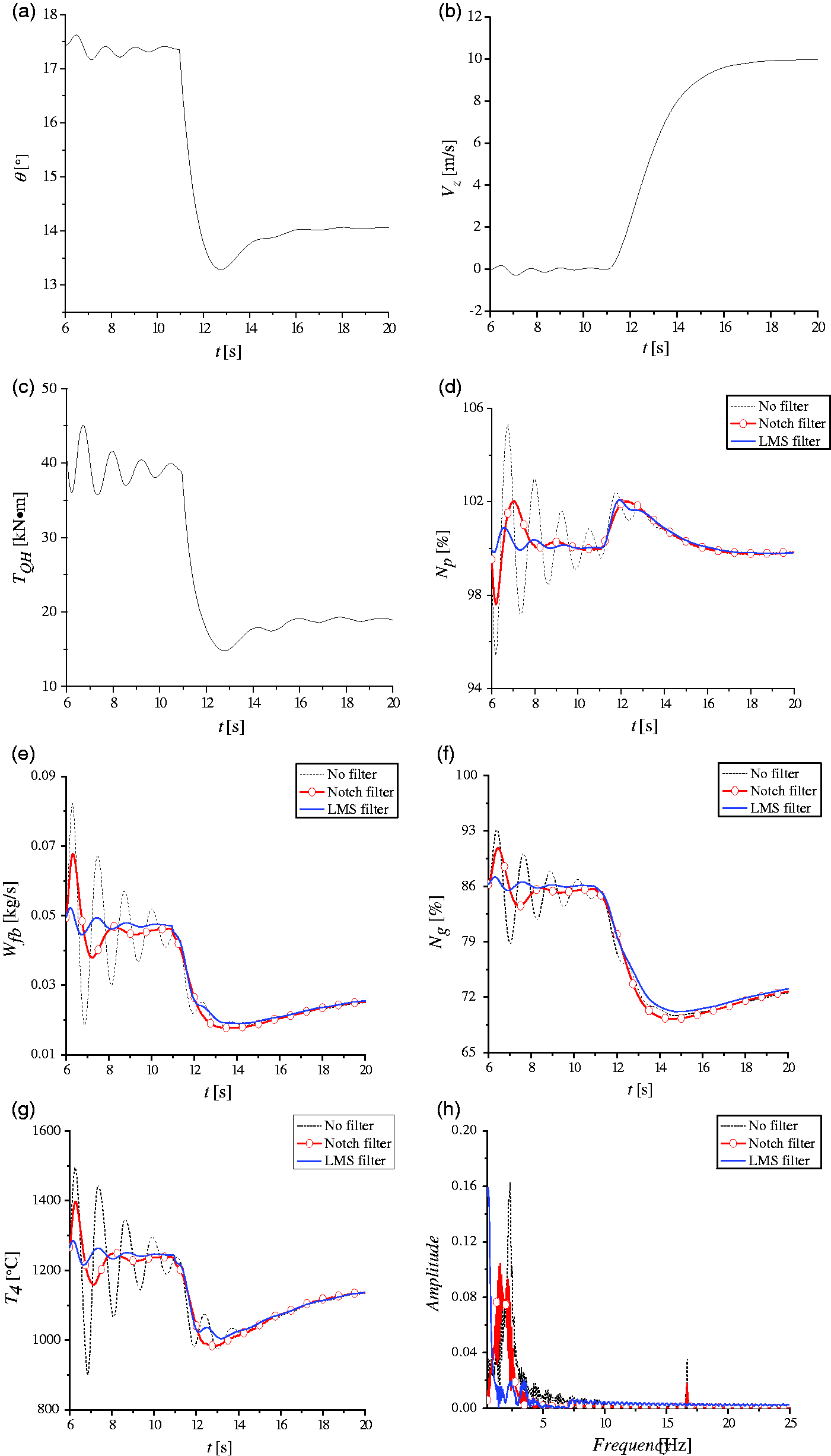
Results of adaptive torsional vibration suppression in autorotation downward. (a) Collective pitch, (b) speed of climbing, (c) rotor demanded torque, (d) relative speed of power turbine, (e) fuel flow, (f) relative speed of gas turbine, (g) temperature before turbine, and (h) FFT of relative speed of power turbine.
As shown in Figure 7(a), the autorotation command is applied at 10 s, and then the collective pitch decreases rapidly to ensure that the blade is not stall and the rotor produces enough thrust. At this time, the driving power is greater than the induced power, and the rotor speed increases. When the climbing speed reaches the maximum, the driving power is approximately equal to the induced power, where the rotor speed keeps constant and the helicopter enters into the stable state.
Figure 7(d) to (g) represents the time-variation curves of the relative speed of power turbine Np, fuel flow Wfb, relative speed of gas turbine Ng and the temperature before turbine T4. From the point of time domain, it is clearly shown that the oscillation is damped a little by the notch filter with constant coefficient; nevertheless, all parameters tend to be smoother with LMS adaptive filter. Figure 7(h) summarizes the amplitude-frequency curves of Np by Fourier transformation. As shown in the figure, the notch filter can reduce the torsional vibration signal at the designed frequency but has little effect on others. On the contrary, although the low-order frequency varies from 1.4 Hz to 2.25 Hz, LMS adaptive filter still can damp all torsional vibrations with the amplitude of the first-order torsional vibration suppressed below 15%, which proves the filtering effect of LMS adaptive filter further.
Predictive control based on adaptive torsional vibration suppression
Under variable rotor speed, the surge margin tends to be more irregular because of the variations of flow capacity and efficiency of the power turbine. Meanwhile, taking into account the prediction ability of rotor demanded torque, the conventional control strategy has the disadvantage of tracking the rotor demanded power. In the interest of better performance and characteristic of helicopter energy and efficiency, the combination of LMS adaptive torsional vibration suppression and predictive control is utilized to enhance the power following ability of the engine, which reduces the droop and overshoot of the power turbine speed, and the high-quality response of the turboshaft engine is realized. The stability of turboshaft engine combined with torsional vibration is acceptable by adopting cascade PID controller, while the dynamic performance is scarcely the best; conversely, the predictive controller can achieve better one.
The structure of predictive control for UH-60A helicopter/engine system based on LMS adaptive torsional vibration suppression is shown in Figure 8. The LMS adaptive filter applied in the feedback loop of the power turbine suppresses the torsional vibration components mixed in Np that enters into predictive control subsequently. The predictive controller is composed of online predictive model of main rotor torque, online predictive model of turboshaft engine and Feasible Sequential Quadratic Algorithm (FSQP) receding optimization algorithm.
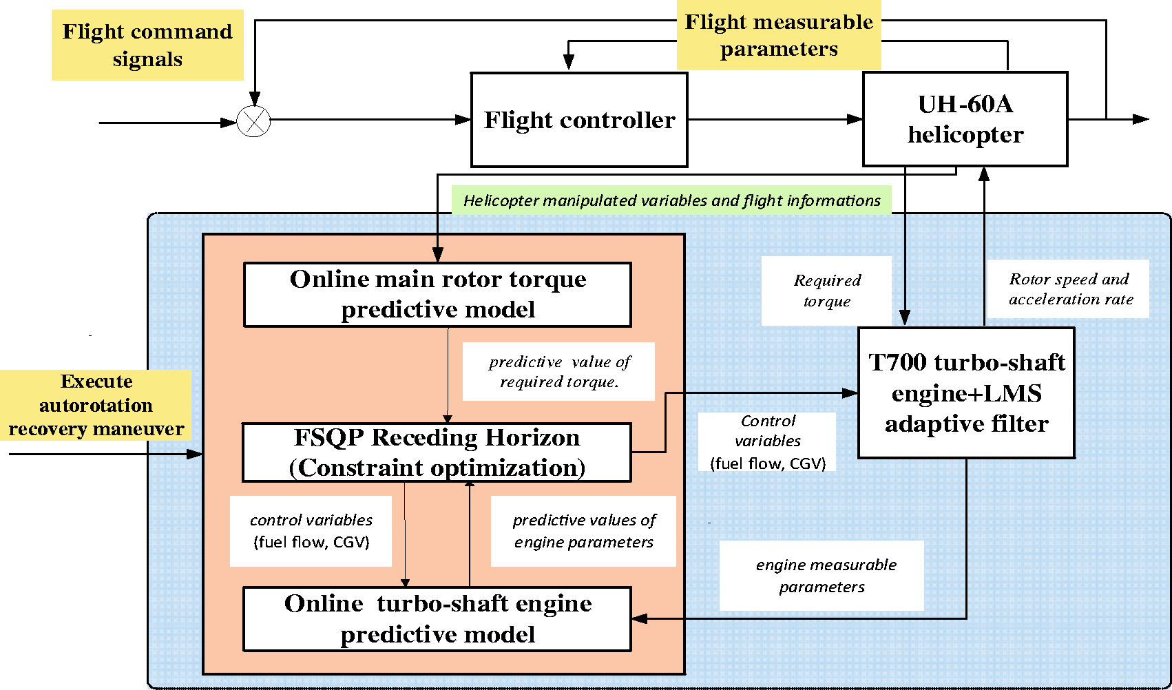
Structure of predictive control based on adaptive torsional vibration suppression.
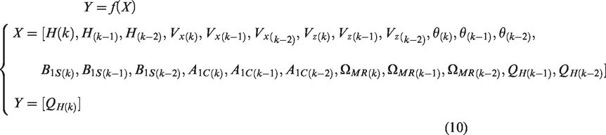
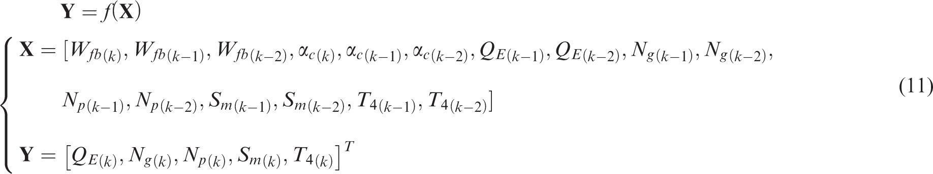
The online predictive model of main rotor torque and turboshaft engine shown in Figure 8 is available by adopting SVR, which is basic of the predictive control. The online predictive model of main rotor torque estimates current rotor demanded torque according to the former data and the current helicopter flight state and suppresses the dynamic interference and torsional vibration through reducing the error between the rotor demanded torque and engine output torque. Assuming that online predictive model of main rotor torque is a two-order system, then the expression is as follows and subscript denotes the sampling time.
The online predictive model of turboshaft engine is adopted to estimate relative parameters of real engine. Similar to main rotor, it is assumed to be a two-order system, which can be expressed as follows
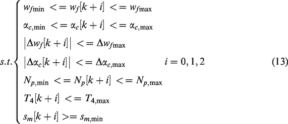
The predictive model obtains the predictive parameters. Through the FSQP algorithm, these parameters can achieve the control target in the premise that the engine is not over-temperature and does not exceed the surge margin. The objective function and necessary constraints are as follows
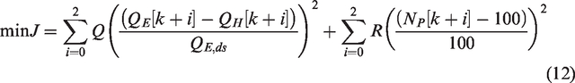
The first part of formula (12) decreases the difference between the torques provided by the engine and demanded by the rotor, thereby reducing the droop of power turbine speed. The second part can reduce the overshoot and droop of the power turbine speed in the optimization process, so that Np keeps about 100%. Q and R represent weight parameters, which can be adjusted if necessary.
According to the above contents, the numerical simulation of predictive control based on adaptive torsional vibration suppression is conducted in helicopter autorotation recovery process in comparison with notch filter in the effect of predictive control. The simulation results are shown in Figure 9.
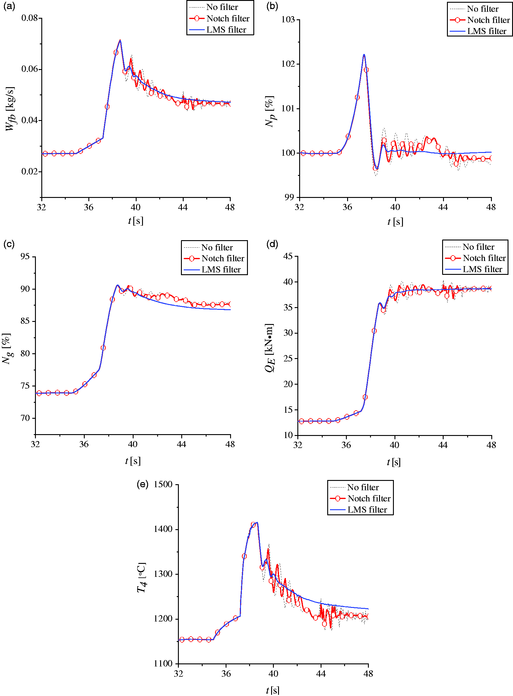
Comparison of effect of predictive control in autorotation recovery. (a) Fuel flow, (b) relative speed of power turbine, (c) relative speed of gas turbine, (d) engine output torque, and (e) temperature before turbine.
Figure 9(a) to (e) represents the comparison results of predictive control effect in the case of no filter, constant notch filter with fixed coefficient and LMS adaptive filter. At 32 s, the command of predictive control is applied, and the clutch is engaged at about 36 s, the output torque of engine increases, resulting in the variety of rotor speed and exciting torsional vibration. Wfb increases rapidly through predictive control after executing the command of autorotation recovery, whose rising rate is restricted by maximum Np. As shown in Figure 9(b), when the difference between the torque provided by the engine and rotor demanded one tends to be great, Np decreases sharply because of inertia. In this case, in order to decrease the droop of Np, Wfb is urgently in need of increase in maximum rate, thereby the engine is large enough to provide greater torque. As shown in Figure 9(b), without any filter, 0.51% droop and obvious low-frequency oscillation of Np occur after the clutch engages, and there exists a steady-state error of 0.24% with the predictive control. There tends to be a little filtering effect with the notch filter applying in the feedback loop of Np. Under these circumstances, the droop is reduced by 0.13%, but the steady-state error of 0.12% seems to be unavoidable. Nevertheless, these curves tend to be smoother through predictive controller based on LMS adaptive filter, where the droop is reduced to about 0.3%, and the steady-state error is no more than 0.01%, whose control effect is satisfactory.
Conclusions
In order to compensate for the inefficiency of conventional notch filter on torsional vibration suppression with variable frequency, LMS adaptive filter has been proposed in this paper. Based on the LMS adaptive torsional vibration suppression, a predictive controller based on SVR has been proposed. Several conclusions have been drawn as follows:
The torsional vibration modes of rotor drive train system have been calculated by MATLAB and ANSYS separately in the paper. It is shown that the errors of the first and second frequency calculated are both less than 15% at constant rotor speed. The rotor speed and fundamental frequency of torsional vibration vary continuously in helicopter autorotation downward process. However, compared with notch filter, LMS adaptive filter can reduce the amplitude of all low-order torsional vibrations with amplitudes less than 15% without increasing the complexity of computational, which proves the more remarkable ability of adaptive torsional vibration suppression The droop of power turbine speed is less than 0.3% and the steady-state error is below 0.01% through adopting the predictive controller based on LMS adaptive torsional vibration suppression. The fast response and high-quality control of turboshaft engine are available. The step size of LMS adaptive filter in the paper is constant, which can realize automatic regulation in the future. The effect of LMS adaptive filter on torsional vibration will be verified in semi-physical simulation experiments in the future.
Footnotes
Declaration of conflicting interests
The author(s) declared no potential conflicts of interest with respect to the research, authorship, and/or publication of this article.
Funding
The author(s) disclosed receipt of the following financial support for the research, authorship, and/or publication of this article: The work has been co-supported by the National Natural Science Foundation of China (Grant/Award Number: 51576096), Qing Lan and 333 Project, Research Funds for Central Universities (No. NF2018003).