
Abstract
To overcome this noise, traditional reactive as well as dissipative mufflers have been used. However, the allowable backpressure and the extra load acting on the cooling tower are limited. So, in order to efficiently reduce the broad noise under a low-pressure drop and a small dead weight, a straight multi-array resonator muffler without sound absorbing wool is required. Multi-array Helmholtz mufflers with complicated Helmholtz resonators were found to be too expensive in manufacturing costs and can be easily accumulated with duct and water. Therefore, a straight multi-array side-branched muffler with an empty chamber is proposed. Here, to efficiently reduce the broadband noise level, eight kinds of mufflers (muffler A–H) with 1–8 raw chambers internally partitioned with concentric perforated plate will also be introduced. To delineate the best acoustical performance of a space-constrained muffler, a numerical assessment using a four-pole matrix method in conjunction with a differential evolution method is adopted. To verify the availability of the differential evolution optimization, a numerical optimization of mufflers A–H at a pure tone (400 Hz) is exemplified. Before the differential evolution operation in broadband noise elimination can be carried out, the accuracy of the mathematical model has been checked using the experimental data. Consequently, a successful approach in eliminating a broadband noise with a low-pressure drop and a dead load using optimally shaped straight multi-array side-branched mufflers and a differential evolution method within a constrained space has been demonstrated.
Introduction
Research on Helmholtz resonators (HRs) has been carried out. Helmholtz 1 and Rayleigh 2 introduced a design for noise reduction using an HR with an opening. Later, an HR model that was analogous to an acoustical filter connected with a small open-top tube used to tune a specified frequency was proposed by Lord and Rayleigh 3 and Ingard. 4 Then, to assess the HR’s resonant frequency, Ingard 4 investigated the end correction for various openings of the HR. Alster 5 developed an improved model for the end correction related to the shape of the chamber. Chanaud 6 extended the study of Ingard 4 for a large-size chamber and analyzed the influence of the resonant frequency with respect to the location of the opening. In addition, Sugimoto 7 and Sugimoto and Horioka 8 presented a new design by adding a matrix type HR within a channel. Subsequently, they utilized shape optimization for a specified tone without space limitations. Later, Cummings, 9 Doria, 10 Fahy and Schofield, 11 and Li and Cheng 12 investigated the resonant frequency of the HR within an enclosure. And, Dickey and Selamet 13 assessed the resonant frequency of a non-symmetric chamber using a three-dimensional boundary element method. Following that, Chanaud 14 discussed the influence of the resonant frequency with respect to various locations of a resonating tube. Then, Hsieh 15 analyzed the acoustical performance of a motor-cycle composed of a wool/non-wool HR silencer using a four-pole matrix and a boundary element method. Finally, Tang 16 investigated the influence of the resonant frequency with respect to a cone-type resonating tube. However, in the above research, the assessment of a muffler’s optimal shape design for a broadband noise hybridized with multiple tones within a constrained space was rarely evaluated.
Previous studies17,18 have assessed shape optimizations of a space-constrained hybrid HR muffler for multi-tones. However, the manufacturing costs for the HR with a resonating tube have been deemed too expensive. So, the noise elimination of pure tones for side-branched resonators (SBRs) has been proposed. 19 Swenson 20 also assessed an experimental study in multiple SBRs. Nevertheless, research of multiple SBRs located within a space-constrained hybrid muffler that deals with a broadband noise hybridized with multiple tones has been somewhat neglected. Nowadays, in order to efficiently reduce the broadband noise under a low-pressure drop and a dead weight often occurring in a tall building’s cooling fan system, a straight multi-array resonator muffler without sound absorbing wool is necessary. That being so, an analysis of the sound transmission loss (STL) and optimized design for a straight multi-array side-branched muffler with an empty chamber under a space-constrained situation will be considered.
In order to reduce a broadband noise and rectify the internal flowing velocity of muffler, eight kinds of straight multi-array side-branched muffles internally partitioned with four concentric perforated plates (muffler A: one array of an SBR element and eight SBR elements paralleled in each array (n = 1, m = 8, h = 4); muffler B: two arrays of SBR elements in series and eight SBR elements paralleled in each array (n = 2, m = 8, h = 4); muffler C: three arrays of SBR elements in series and eight SBR elements paralleled in each array (n = 3, m = 8, h = 4); muffler D: four arrays of SBR elements in series and eight SBR elements paralleled in each array (n = 4, m = 8, h = 4); muffler E: five arrays of SBR elements in series and eight SBR elements paralleled in each array (n = 5, m = 8, h = 4); muffler F: six arrays of SBR elements in series and eight SBR elements paralleled in each array (n = 6, m = 8, h = 4); muffler G: seven arrays of SBR elements in series and eight SBR elements paralleled in each array (n = 7, m = 8, h = 4); muffler H: eight arrays of SBR elements in series and eight SBR elements paralleled in each array (n = 8, m = 8, h = 4)) within a fixed space are also presented. To facilitate a numerical assessment, a differential evolution (DE) method with a real coded population, not a binary or a gray representation, is adopted. By adjusting the muffler’s shape, varying the acoustical element, and using the DE, the optimal acoustical performance of the broadband mufflers can be achieved.
Theoretical background
As indicated in Figure 1, there is a broadband fan noise located in a tall building. Eight kinds of mufflers A–H internally partitioned with four concentric perforated plates shown in Figures 2 and 3 were adopted for dealing with this noise. Before the acoustical fields of the mufflers were analyzed, the acoustical elements had been identified. As shown in Figure 2, two types of muffler components, including straight duct and SBRs, are identified and marked as I and II. The outline dimension of the mufflers is shown in Figure 3.
A broadband fan noise located at a tall building.
Acoustical field for eight kinds of straight multi-array side-branched mufflers internally partitioned with four concentric perforated plates.
Dimensions for eight kinds of straight multi-array side-branched mufflers internally partitioned with four concentric perforated plates.
Sound transmission loss of mufflers A–H
As derived in previous work21–24 and Appendix A, the system matrix of the ith muffler with n layer and m partitions of SBRs (n = i and m = 8) is
The simplified form is expressed in a matrix as
Back pressure of mufflers
The backpressure of the ith muffler with n segments is27,28

Overall sound power level
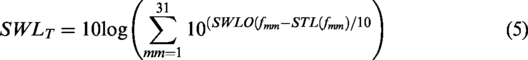
The overall SWLT silenced by the muffler at the outlet is
Objective function
By using the formulas of equations (1) to (5), the objective function used in the DE optimization with respect to each type of muffler was established. For the ith muffler (i of 1–8 is respect to A–H), the objective function in maximizing the STL at one tone (f1) is

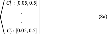
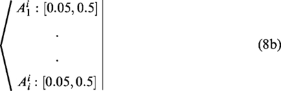
Here, Q (the flow rate), A, B, D1 are preset at 0.01 m3/s, 0.05 m, 0.05 m, and 0.9 m. The design parameter set for the ith muffler, Xi, is

The related constrained situation specified in Table 2 is
Similarly, the objective function in minimizing the overall SWLT hybridized with thirty-one tones (f1–f31) specified in Table 1 is

An unsilenced SWLO inside a muffler inlet.
The ranges of parameters for mufflers A–H.
Model check
Before performing the DE optimal simulation on mufflers, an accuracy check of the mathematical model on the acoustical elements of the SBR (II) is performed using the experimental data. As depicted in Figure 4, the theoretical and experimental data are in agreement. Therefore, the proposed fundamental mathematical model for the SBR is acceptable. Consequently, the model linked with the numerical method is applied to the shape optimization in the following section.
An accuracy check of the mathematical model on the acoustical elements of a single side-branched resonator (n = 1, m = 1) is performed using the experimental data.
Case study
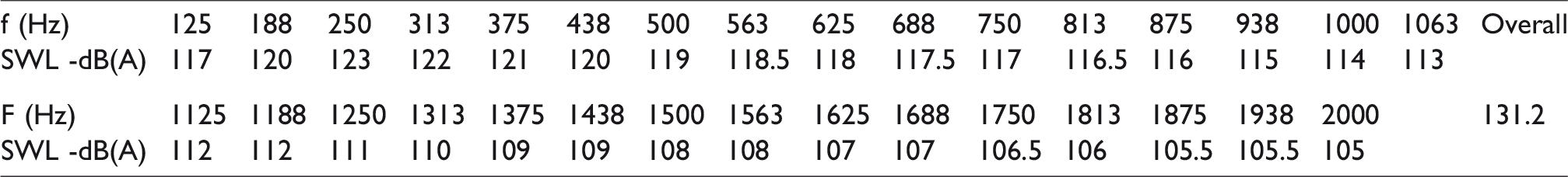
The noise reduction of a broadband noise emitted from a cooling fan system is introduced and shown in Figure 1. The original sound power level (SWLO) inside the muffler’s inlet is shown in Table 1 where the overall SWL reaches 131.2 dB. To efficiently reduce the cooling fan room’s noise with a low backpressure and a dead load utility, a straight multi-array side-branched muffler with empty chambers is necessary. Here, eight kinds of straight multi-array side-branched mufflers (mufflers A–H) that can efficiently eliminate a broadband noise are considered.
To obtain the best acoustical performance within a fixed space, numerical assessments linked to a DE optimizer are applied. Before the minimization of a broadband noise is performed, a reliability check of the DE method by maximization of the mufflers’ STL at a targeted tone (400 Hz) is performed. As shown in Figure 1, the available space for a muffler is 1.7 m in width and 1.7 m in height. The length of a SBR is confined within a 0.05–0.5 m. The radial gap (B) and axial gap (A) are preset at 0.05 m. The flow rate (Q) of the cooling fan system is preset at 0.01 (m3/s). The corresponding OBJ functions and ranges of the design parameters are summarized in equations (6) to (9) and Table 2.
Differential evolution method
There has been, for years, a focused effort to evolve evolutionary algorithms (EAs) that efficiently pursue suitable global solutions for engineering quandaries. One method, DE, a stochastic direct search method, has, itself, been acknowledged as one of the best. Additionally, because of the necessities of the classical gradient methods EPFM, IPFM and FDM as acceptable starting points (design data) prior to optimization being performed, accuracy is limited. 29 It should also be noted that before the DE is performed, the selection of starting data is rendered unnecessary. In light of this, DE then becomes the adopted optimizer utilized in the muffler’s shape optimization.
Differential evolution, a population-based search algorithm, was invented by Storn and Price.30,31 DE uses a real-valued vector for the design variable and evaluates for optimization by using mutation, crossover, and selection. The mutation operator of DE is executed by multiplying a scaling factor (known as the mutation constant) to a vector difference. Subsequently, a new offspring is generated by using crossover and selection. Because there are fewer control parameters compared to other population-based algorithms, DE is becoming increasingly popular worldwide. The DE procedures and parameter settings are described below.
Initialization
The initial population of DE is generated randomly between the lower and upper bounds for each design variable. For a specified population (NP), the initial ith design vector (Xi) is generated by the random value (
Mutation operation
In an m-dimensional search space, for each target vector (
Crossover operation
In order to increase the diversity of the perturbed parameter vectors to expand the searching space during the DE operation, a crossover mechanism is adopted. The trial vector (
The mechanism of crossover for a target vector and a mutant vector in the DE method.
Also, the initial mutant vector is expressed as

For the jth searching space, using the crossover on mutant vector (
The new trial vector (
Estimation and selection
The new (next) generation of the target vector (
Program terminated
To simplify the numerical assessment of the DE method, a maximal evolution iteration (itermax) is preset in advance. As indicated in Figure 6, the process is continually repeated until the predetermined number (itermax) of the outer loop is reached.
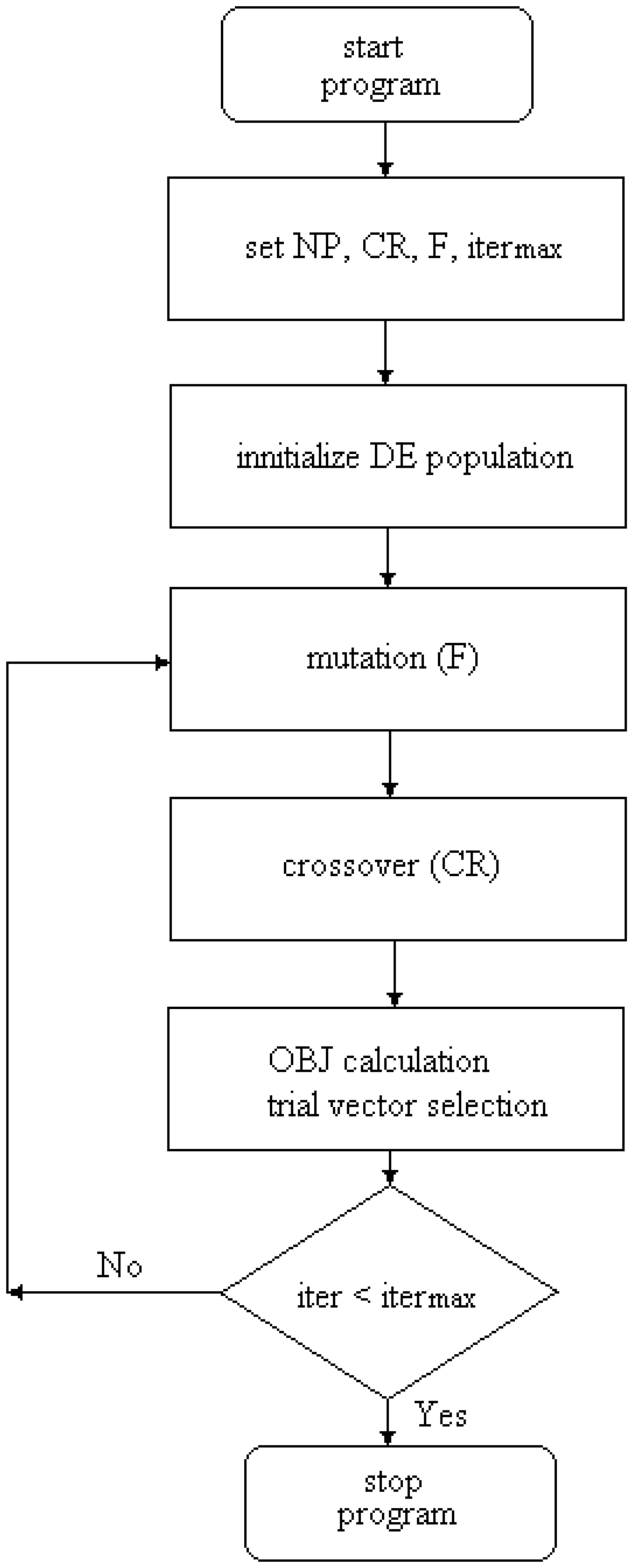
The flow diagram of the DE optimization.
Results and discussion
Results
The accuracy of the DE optimization depends on four types of DE parameters including NP (population number), CR (crossover rate), F (mutation factor), and itermax (maximum iteration). According to Rainer and Kenneth, 32 an appropriate number for population (NP) is preset as 5*m where m is the number of parameters. To achieve a good optimization, the following DE’s control parameters are varied step by step:
CR (0.1, 0.3, 0.5, 0.7, 0.9); F (0.1, 0.3, 0.5, 0.7, 0.9); itermax (50, 100, 500).
Two results of optimization (one, pure tone noises used for the DE’s accuracy check; and the other, a broadband noise emitted from an exhaust fan) are described below.
Pure tone noise optimization
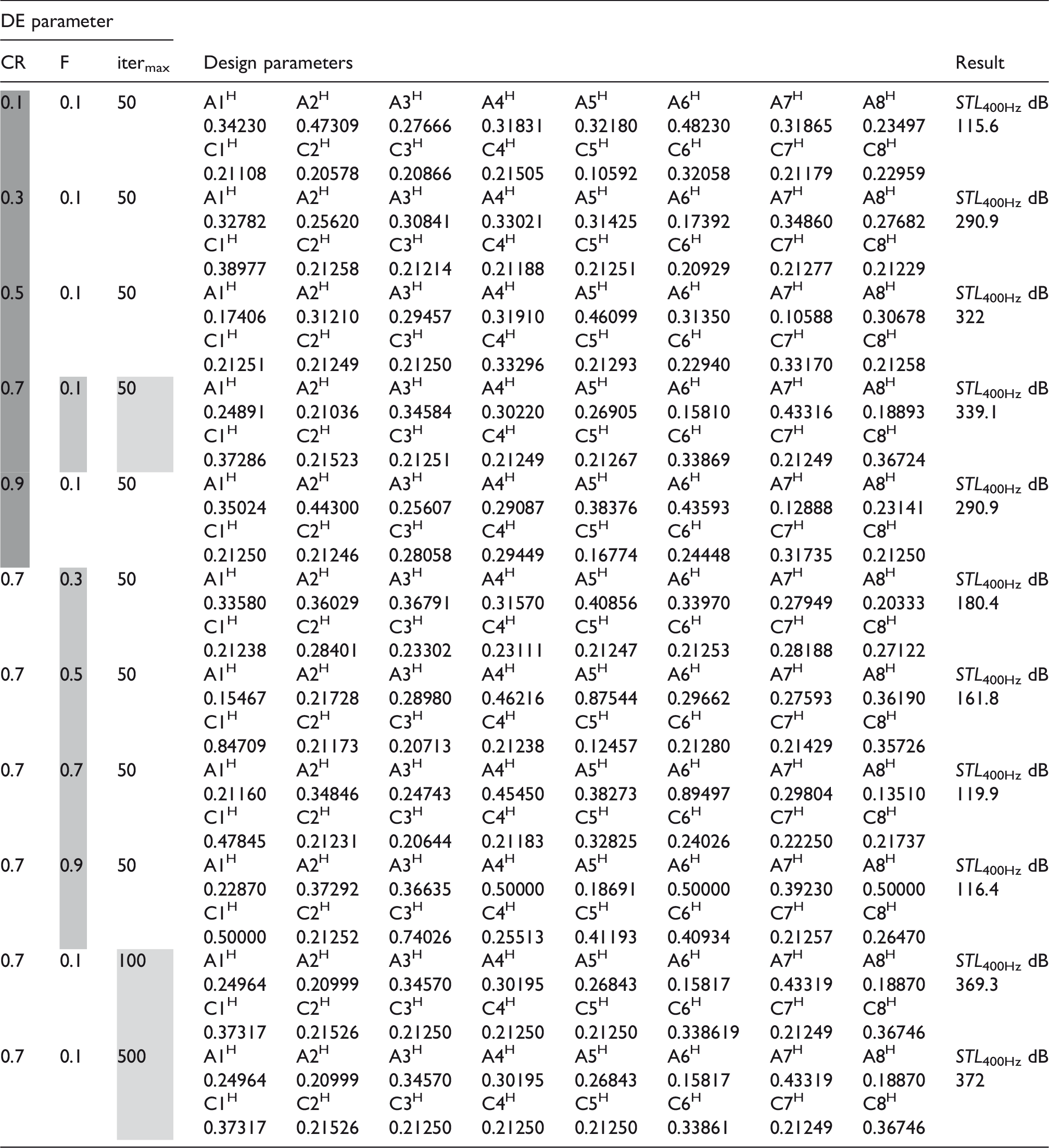
Before dealing with a broadband noise, the STL’s maximization with respect to a one-tone noise (400 Hz) for muffler H is introduced for a reliability check on the DE method. By using equation (6), the maximization of the STL with respect to muffler H (muffler H: eight arrays of SBR elements in series with eight parallel SBR elements (n = 8, m = 8, h = 4)) at the specified pure tone (400 Hz) was performed first. As indicated in Table 3, eleven sets of DE parameters are tried in the muffler’s optimization. Obviously, the optimal design data can be obtained from the last set of DE parameters at (CR, F, itermax) = (0.7, 0.1, 500). Using the optimal design in a theoretical calculation, the optimal STL curves with respect to various DE parameters (CR, F, itermax) are plotted and depicted in Figures 7 to 9. As revealed in Figures 7 to 9, using the DE control parameter set of (CR, F, itermax) = (0.7, 0.1, 500), the STL will be precisely maximized at the desired frequency (400 Hz).
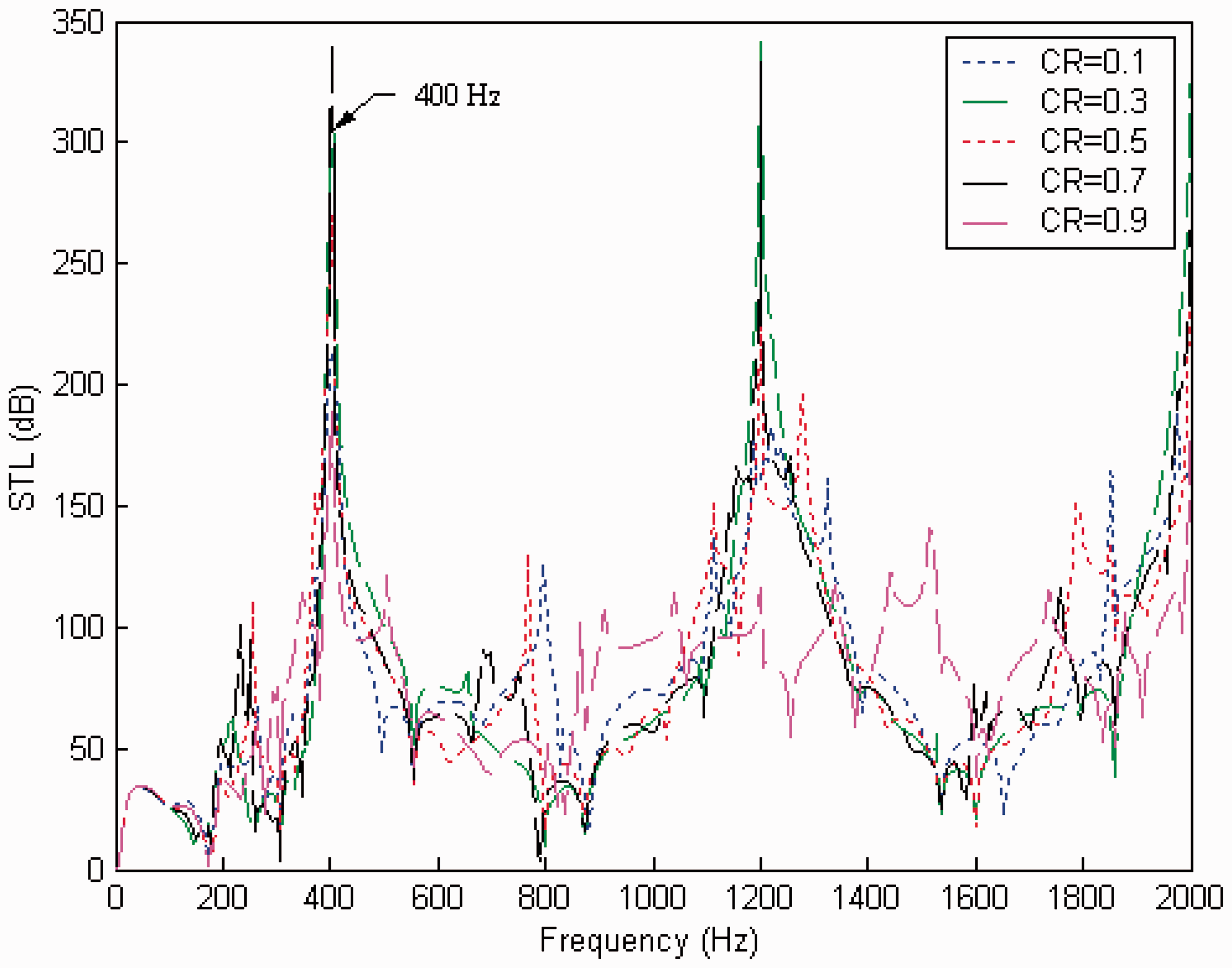
STL with respect to various CRs (muffler H: NF = 80, F = 0.1, iter = 50, target tone = 400 Hz).
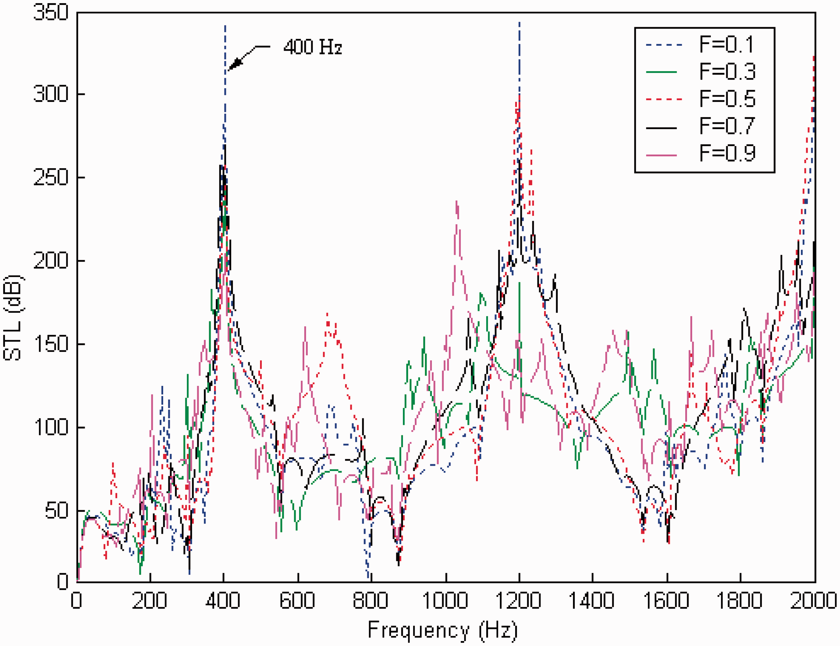
STL with respect to various Fs (muffler H: NF = 80, CR =0.7, iter = 50, target tone = 400 Hz).
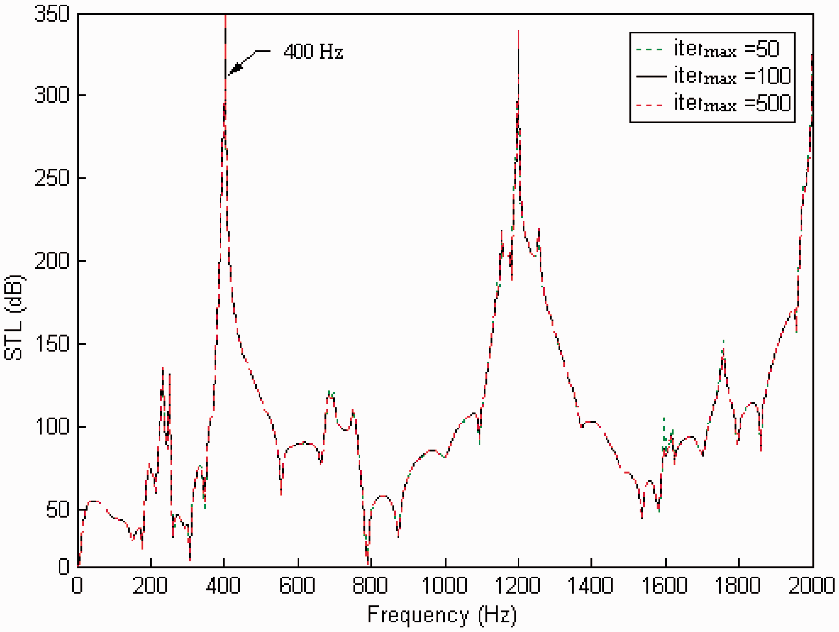
STL with respect to various iters (muffler H: NF = 80, CR =0.7, F =0.1, target tone = 400 Hz).
Optimal STL for muffler H (i = 8; eight arrays of SBR elements in series with eight parallel SBR elements for each array; n = 8, m = 8, and h = 4) (NP = 80; targeted tone of 400 Hz).
STL: sound transmission loss; SBR: side-branched resonator; DE: differential evolution; CR: crossover rate.
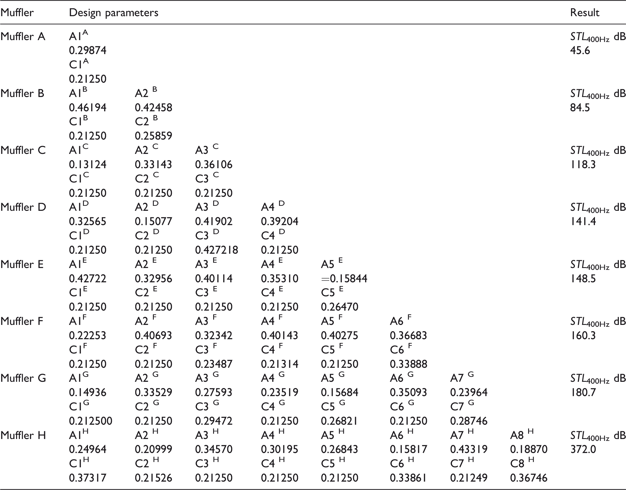
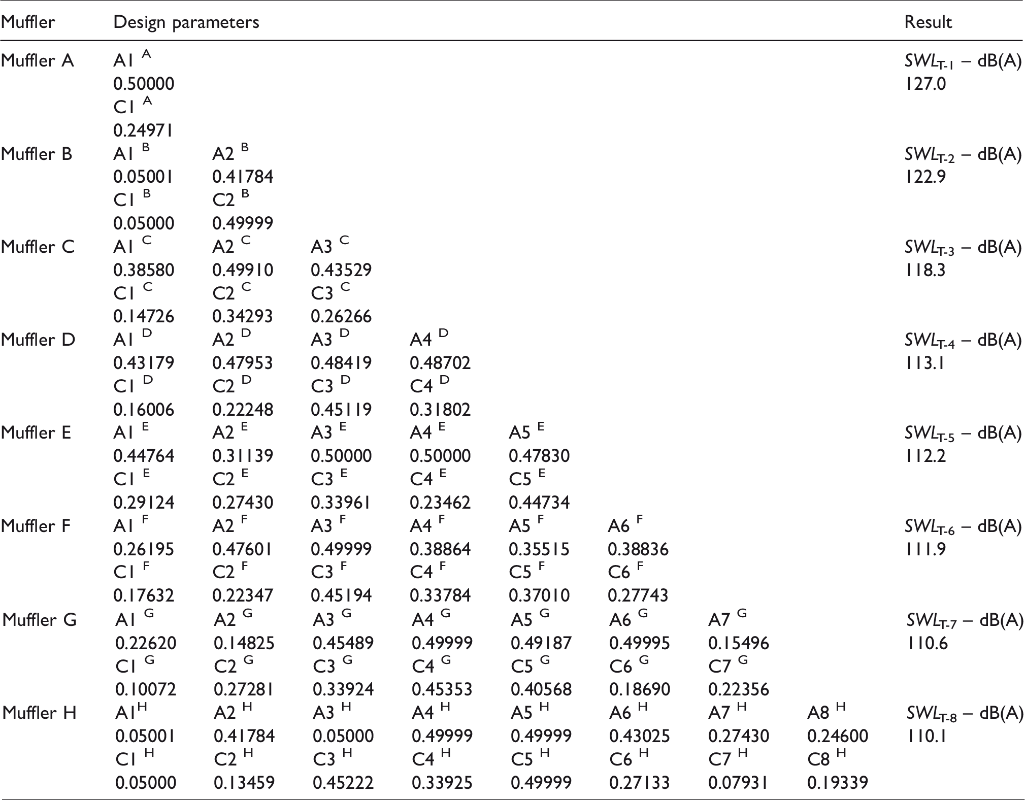
In order to appreciate the acoustical influence of the STL with respect to the number of SBR rows (n), the shape optimization of mufflers A–G with 1–7 rows of SBRs has been performed. Using the equations (6) and (8) in conjunction with the best DE control parameter set of (CR, F, itermax) = (0.7, 0.1, 500), the resulting optimal design parameters of mufflers A–H are obtained and summarized in Table 4. Using the optimal design sets in a theoretical calculation, the optimal STL curves with respect to mufflers A–H are plotted and depicted in Figures 10 and 11. As revealed in Figures 10 and 11, the STLs of the mufflers are precisely maximized at the target frequency (400 Hz); in addition, the STL at the target frequency (400 Hz) will increase if the number of n increases. Therefore, the DE optimizer is reliable in the optimization process.
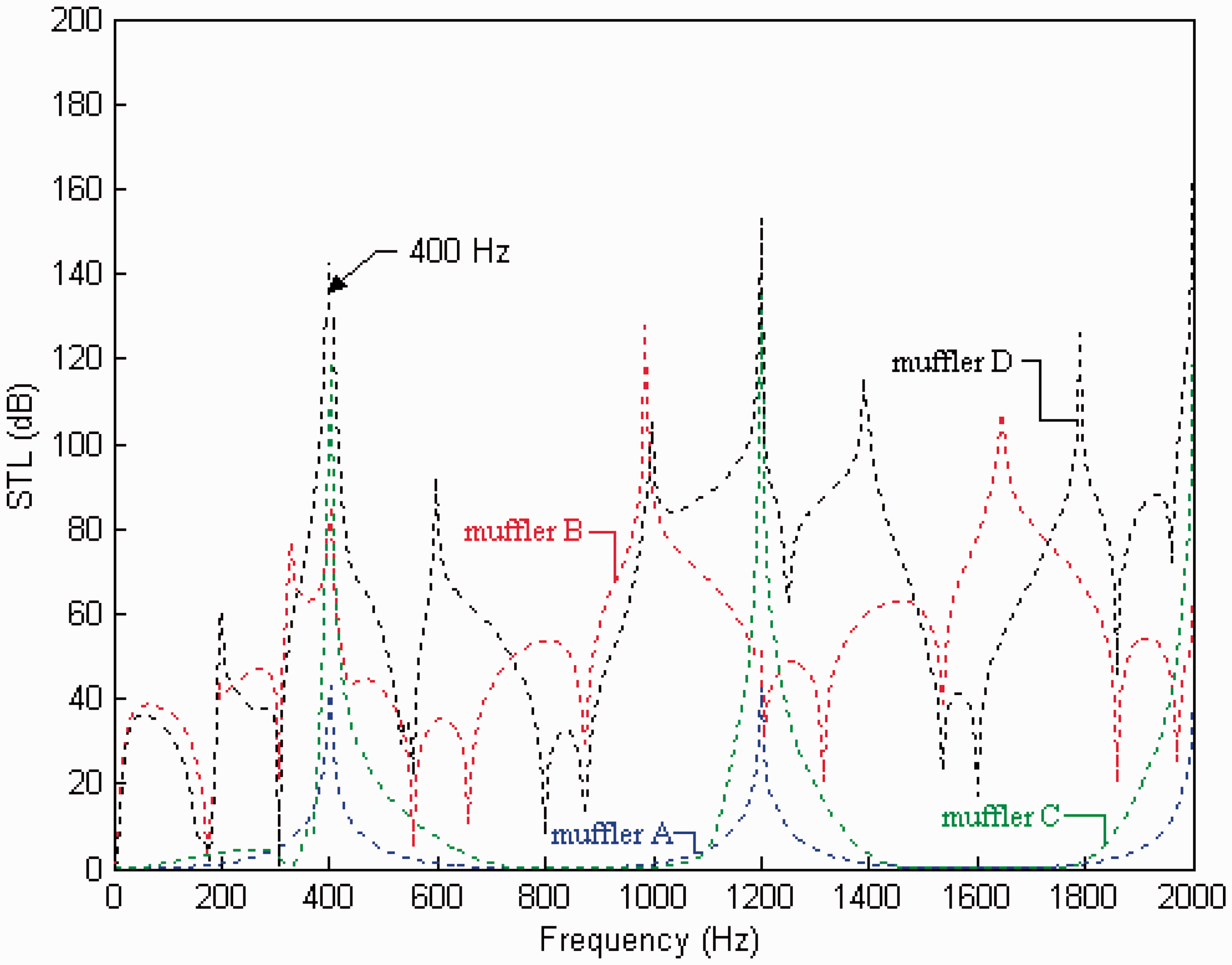
Comparison of the optimal STLs of four kinds of mufflers (mufflers A, B, C, and D) (target tone: 400 Hz).
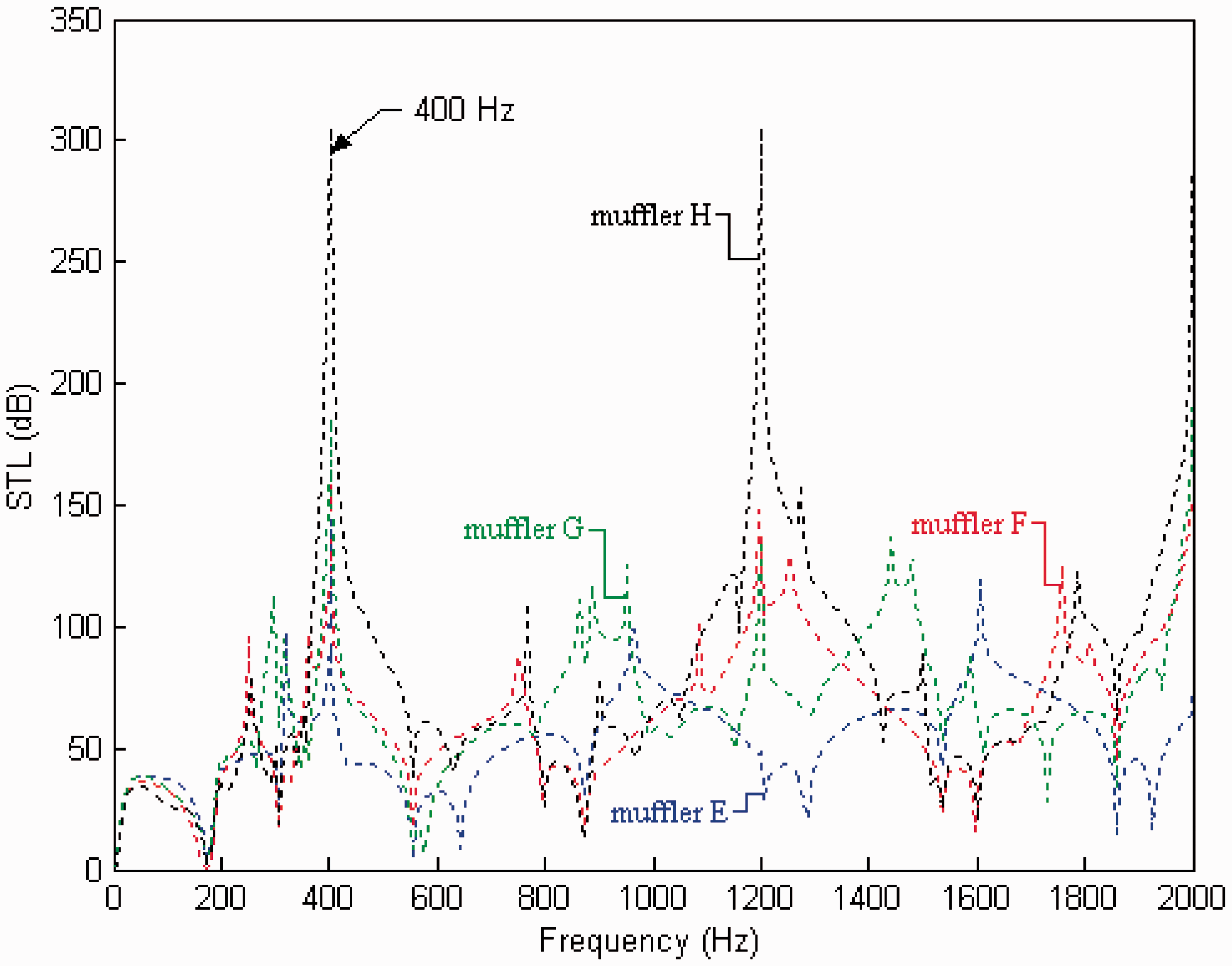
Comparison of the optimal STLs of four kinds of mufflers (mufflers E, F, G, and H) (target tone: 400 Hz).
Comparison of the maximized STL of eight kinds of mufflers (mufflers A–H) (targeted tone = 400 Hz).
STL: sound transmission loss.
Moreover, in order to evaluate the acoustical influence of the STL with respect to the number of parallel SBRs for each row (m), muffler A (n = 1, h = 4) with various sections (m = 2, 3, 4, 5, 6, 7, 8) is investigated. The optimal STL of muffler A (n = 1, h = 4) with various sections (m = 2, 3, 4, 5, 6, 7, 8) is assessed and plotted in Figure 12. It is seen in Figure 12 that there is no change if the section number of m increases.
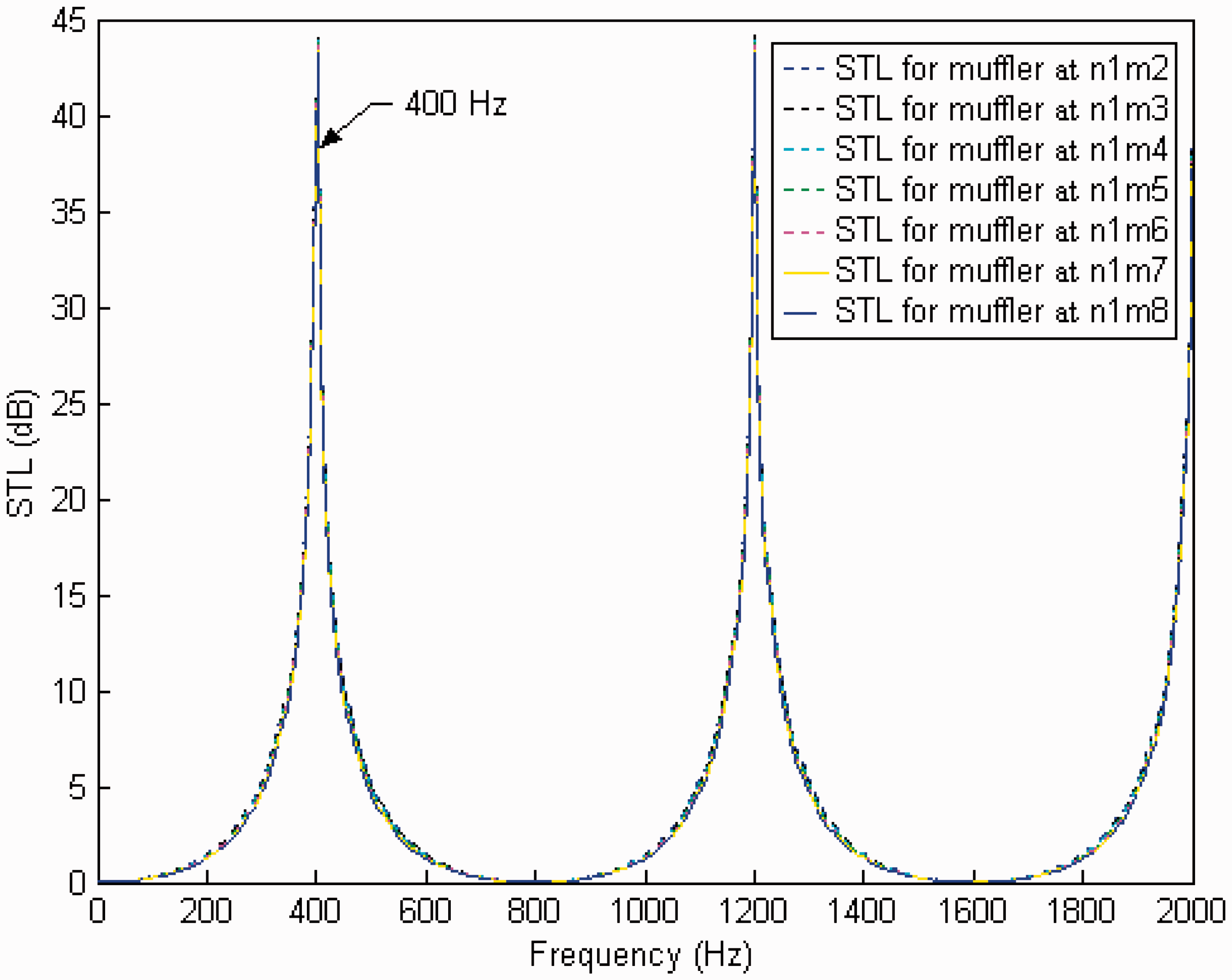
Comparison of the optimal STLs of seven kinds of mufflers (muffler A (n = 1) with various sections (m = 2, 3, 4, 5, 6, 7, 8; h = 1) (target tone: 400 Hz).
Broadband noise optimization
Similarly, considering equations (7) to (9) and using the same DE parameters in the broadband optimization process, the minimization of the SWLT-1 ∼ SWLT-8 with respect to mufflers A–H was performed and shown in Table 5. As illustrated in Table 5, the resultant sound power levels with respect to mufflers A–H have been reduced from 131.2 dB(A) to 127 dB(A), 122.9 dB(A), 118.3 dB(A), 113.1 dB(A), 112.2 dB(A), 111.9 dB(A), 110.6 dB(A), and 110.1 dB(A). Using this optimal design in a theoretical calculation, the optimal STL curves with respect to various mufflers are plotted and compared with the original SWL depicted in Figures 13 and 14.
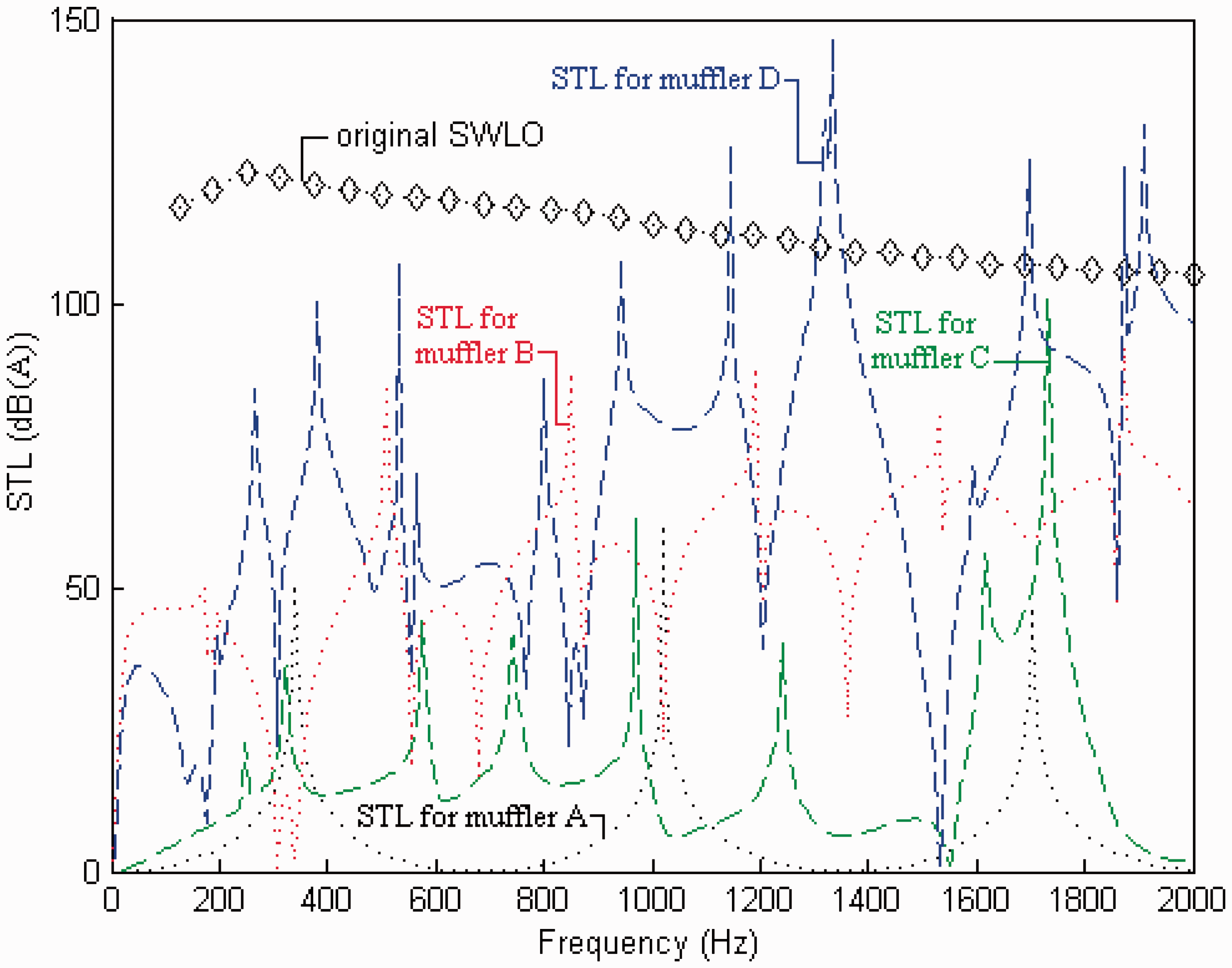
Comparison of the optimal STLs of four kinds of mufflers (mufflers A, B, C, and D) and the original SWL (broadband noise).
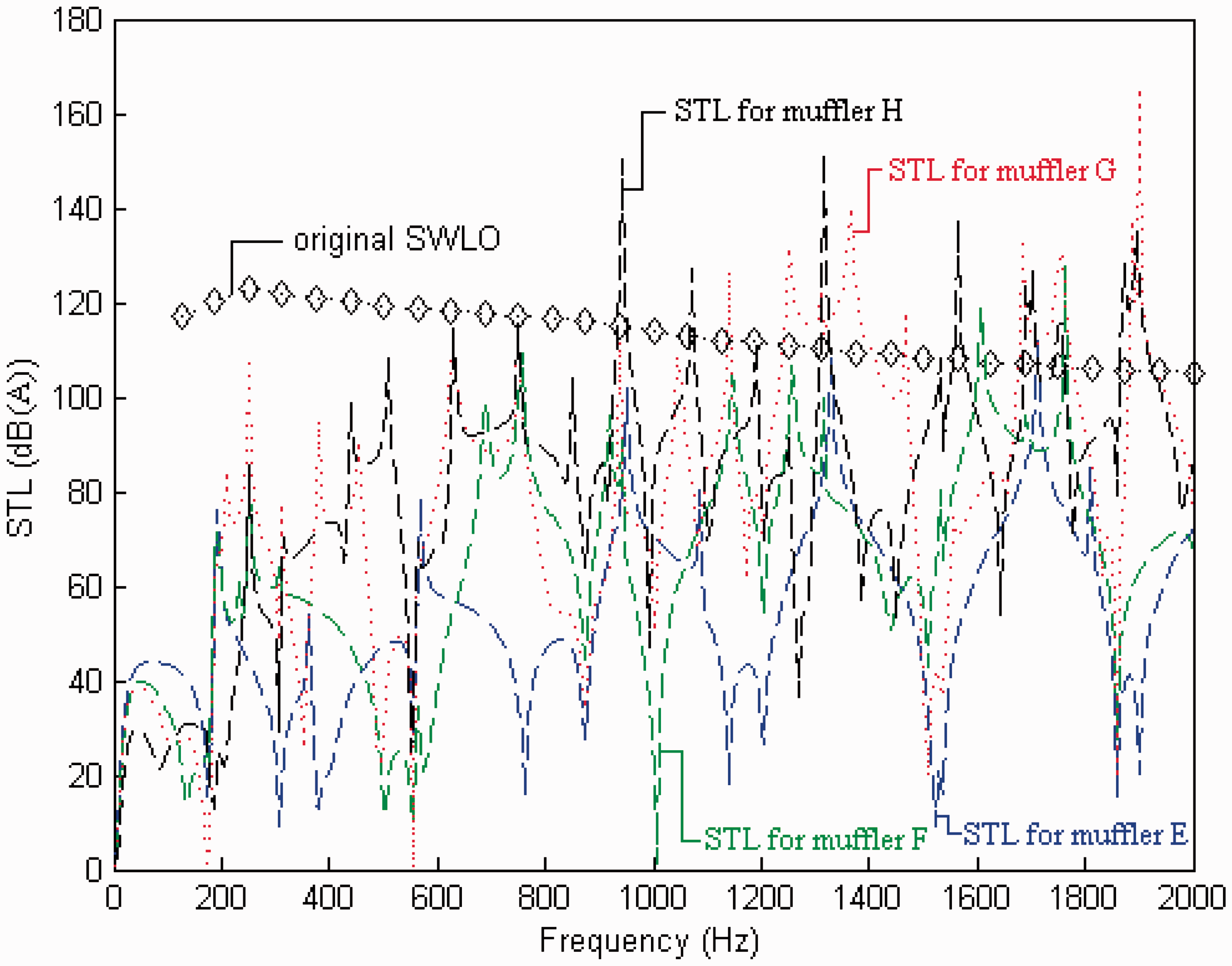
Comparison of the optimal STLs of four kinds of mufflers (mufflers E, F, and H) and the original SWL (broadband noise).
Comparison of the minimized SWLT of eight kinds of mufflers (mufflers A–H) (broadband noise).
Discussion
To achieve a sufficient optimization, the selection of the appropriate DE parameter set is essential. As indicated in Table 3, the best DE set for muffler H at the targeted pure tone noise of 400 Hz has been shown. The related STL curves with respect to various DE parameters are plotted in Figures 7 to 9. Figures 7 to 9 reveal the predicted maximal value of the STL is located at the desired frequency. Therefore, the reliability of DE optimizer used in the optimization of the mufflers is assured.
To realize the acoustical influence with respect to the number (n) of the SBRs in series, mufflers A–H have been optimized. The related STLs with respect to various mufflers have been plotted in Figures 10 and 11. As indicated in Figures 10 and 11, the STL at the target frequency of 400 Hz will increase when n increases. Moreover, to clarify the acoustical effect with respect to the number (m) of the SBRs in parallel, muffler A (n = 1, h = 4) with various sections (m = 2, 3, 4, 5, 6, 7, 8) is investigated. The optimal STL of muffler A (n = 1, h = 4) with various sections (m = 2, 3, 4, 5, 6, 7, 8) is assessed and plotted in Figure 12. Obviously, because of the fixed section, there is no STL difference even though the fixed section area is divided into more parts.
In approaching a broadband noise, thirty-one target frequencies with a span of 63 Hz shown in Table 1 are preset. After the SWL minimization at thirty-one target frequencies (f1–f31), the optimal design for eight kinds of mufflers within a limited space has been discussed and shown in Table 5 and Figures 13 and 14. Results reveal that the overall noise reduction with respect to mufflers A–H (n = 1,…,8; m = 8; h = 4) is 4.2 dB(A), 8.3 dB(A), 12.9 dB(A), 18.1 dB(A), 19 dB(A), 19.3 dB(A), 20.6 dB(A), and 21.1 dB(A). Obviously, muffler H is superior to the other three mufflers. Moreover, Figures 13 and 14 indicate that the band of the STL curve will be widened and the noise elimination at thirty-one target frequencies (f1–f31) will increase when n increases.
Additionally, as depicted in Figures 2 and 3, by using the cooling tower’s venting duct internally partitioned with four concentric perforated plates, the dimension of the airways is 0.1 m. Its corresponding cutoff frequencies
Moreover, based on equation (4), the back pressures with respect to mufflers A–H constrained with 0.5 m in length is 0.000003 Pa. Therefore, the backpressure is small enough and can be neglected.
Consequently, more number of SBRs (n) in series will efficiently broaden the STL curve; however, more parallel SBRs (m), which are divided in a confined section area of the muffler, will have no effect in improving the muffler’s acoustical performance.
Conclusion
In order to efficiently reduce the broadband noise of cooling tower which needs a low pressure drop and a small dead weight, a straight multi-array resonator muffler without sound absorbing wool is required. It has been shown that straight multi-array side-branched mufflers with a low backpressure and a low dead load developed in this paper can be used in dealing with a broadband noise. The optimization of muffler shapes within a limited space can be easily and efficiently carried out by using a four-pole transfer matrix as well as a DE optimizer. Three kinds of DE parameters (CR, F, and itermax) play essential roles in the solution’s accuracy during the DE optimization. As indicated in Figures 7 to 9, the predicted maximal value of the STL is precisely located at the desired frequency. Hence, the tuning ability established by adjusting the design parameters of muffler H is reliable.
As illustrated in Figures 10 and 11, the STL at the target frequency of 400 Hz will increase when the number of SBRs (n) in series increases. In addition, Figure 12 indicates that the STLs for a various number (m) of parallel SBRs at a specific muffler section will have no change even though the fixed section area is divided into parts of SBRs.
As can be seen in Table 5 and Figures 13 and 14, the overall noise reduction with respect to mufflers A–H (n = 1,…,8; m = 8) reaches 4.2 dB(A), 8.3 dB(A), 12.9 dB(A), 18.1 dB(A), 19 dB(A), 19.3 dB(A), 20.6 dB(A), and 21.1 dB(A). Muffler H with more SBRs (n) in series is superior to the other seven mufflers. It is obvious that the band of the STL curve will be efficiently widened and the noise elimination at thirty-one target frequencies (f1–f31) will increase when the number of SBRs (n) in series increases.
Consequently, the approach used for the optimal noise elimination in the broadband noise using space-constrained straight multi-array SBR mufflers with a low backpressure and a low dead weight proposed in this study is quite important and can be efficiently achieved.
Footnotes
Acknowledgements
The author also would like to thank the reviewers for his/her valuable comments.
Declaration of conflicting interests
The author(s) declared no potential conflicts of interest with respect to the research, authorship, and/or publication of this article.
Funding
The author(s) disclosed receipt of the following financial support for the research, authorship, and/or publication of this article: The author acknowledges the financial support of the National Science Council (NSC 102-2622-E-235-001-CC3, ROC).