
Abstract
In-wheel motor-driven vehicles are the development trend for future vehicles due to its high energy efficiency and low emission as well as its flexibility to achieve independent steering, driving, etc. However, the weighted wheel of in-wheel electric vehicles involves more unexpected unsprung vibrations, which imposes adverse effect on vehicle ride comfort. In addition, there exists an invariant point around the unsprung resonance frequency in both controlled and uncontrolled suspensions, which greatly limits the elimination of unsprung adverse effect of in-wheel electric vehicles. In this paper, a combined structure is proposed to eliminate the unsprung adverse effect. The structure is composed of the vehicle suspension and a tuned mass damper, which are both controlled by a sliding mode controller, aiming at eliminating the unsprung adverse effect as well as improving ride comfort across the whole frequency spectrum. The tunes mass damper is used to get rid of the constraint of the invariant point. The simulation and hardware-in-the-loop results show that the root mean square of the sprung mass acceleration and tire deflection is reduced by 31.2% and 2.2% respectively, which indicates that the proposed method is effective and ride comfort is greatly improved.
Introduction
With the development of automotive industry, environment pollution and energy shortage become urgent issues to be solved. According to the U.S. Environmental Protection Agency (EPA) report, 1 about 75% of carbon monoxide pollution in the United States is caused by the traditional engine vehicles. On the other hand, transportation contributes to 28% of energy consumption, most of which is the gasoline. 2 Hence, electric vehicles (EVs) are attracting more and more attention for their high energy efficiency and low emission. 3 The in-wheel motor, as one of innovative driving alternative for EVs, has many advantages such as space-saving, driveline component reduction, and so on. Many researchers have studied the steering and driving characteristics of in-wheel electric vehicles (IEVs).4–6 However, the increasing weight restricts the application of the in-wheel motor in EVs, which would affect the road-holding and ride qualities.7,8 Therefore, overcoming the unsprung adverse effect becomes crucial and challenging for the development of IEVs.
In recent years, elimination of unsprung adverse effect has received considerable attention from both academic and industries. Some manufacturers reduce the unsprung mass by adopting light materials in the rim and suspension components. 9 BMW 5-series uses aluminum magnesium alloy for lightweight wheels. 10 Volvo adopts an all-aluminum rear axle assembly to reduce the unsprung weight. 11 According to their tests, the unsprung mass transmits less road and tire noise to the chassis due to the lightweight. 12 Although the adoption of light materials can reduce the unsprung weight, the limited mass decrement and the high cost can hardly meet the requirements for IEVs. In other methods, the in-wheel suspension system (ISS) also attracted attention of many researchers and manufacturers. Rojas Rojas et al. 13 presented an ISS, which connects the in-wheel motor to the unsprung mass in a flexible manner. Actually, the structure isolates the driven motor from the unsprung mass. Similar structures have also been developed earlier by Bridgestone 14 and Michelin. 15 Although the unsprung weight of IEVs can be reduced by ISS successfully, but the complex structure and expensive costs limit its application in productions. The controlled suspensions, as a proven technique, also have the potential ability to eliminate the unsprung adverse effect. Many controllers, including semi-active and active suspensions, have been widely studied in the past, such as sky-hook, 16 ground-hook, 17 LQR,18,19 model predictive control,20,21 sliding mode control,22–24 and so on. However, although the existing controlled suspensions can well improve ride qualities at low frequency, the existence of invariant points makes it tough to remove the unsprung adverse effect. 25
This paper tries to develop a simple and effective structure to overcome the unsprung adverse effect. This structure combines the controlled suspension with a controlled tuned mass damper (TMD), in which the TMD is used to get rid of the constraint of the invariant point. This study is different from the former research in that it explores the invariant properties of the uncontrolled structure (a passive suspension with a passive TMD), which gives an insight into the theory of vibration absorption. In practice, the controlled suspension system includes large numbers of nonlinear component, such as the actuator, the control system, and so on.26–28 Therefore, the sliding mode controller is selected as the controller of the vehicle suspension and TMD for its excellent stability and outstanding performance with two or more control objectives.22,24,29 As a result, the proposed structure can eliminate the unsprung adverse effect totally as well as improve the ride comfort across the whole frequency spectrum. In addition, the hardware-in-the-loop simulation indicates that the designed controller also behaves well in the presence of nonlinearities.
This paper is organized as follows: the upcoming section reviews the problems, including unsprung adverse effect and the invariant properties. Next, system modeling and the analysis of invariant property are processed and the sliding mode controller suited to the combined structure is designed. An inverse model of the controllable damper is proposed for the practical application in a later section. Subsequently, the numerical study as well as hard-ware-in-loop simulation are presented. Finally, the application of the proposed method in the full car model are studied and conclusions are provided in the last section.
Problem review
Unsprung adverse effect
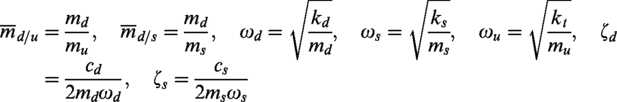
The ride comfort and road-holding are the main concerns in the suspension design. With regard to IEVs, the in-wheel motor introduces unwanted weight to the unsprung mass, which adversely affects the suspension performance. In this paper, the ratio of the unsprung mass to the sprung mass is defined as the mass ratio
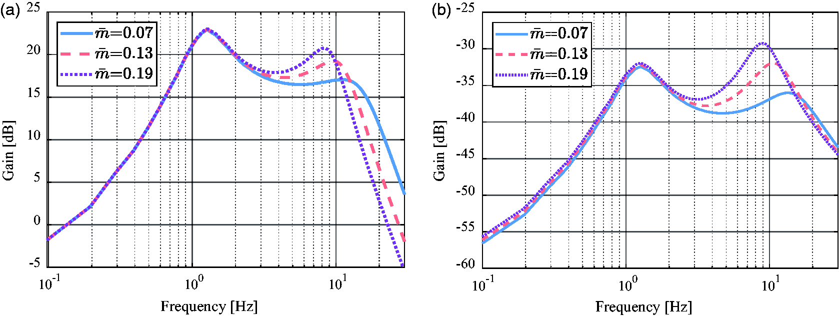
Influence of the mass ratio
As shown in Figure 1(a), the gains of the sprung mass acceleration increase with
Invariant points
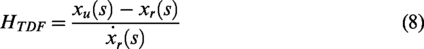
In general, the vehicle vertical dynamics performance can be improved with the controlled suspensions. Therefore, the controlled suspension is the first choice to eliminate the unsprung adverse effect due to its good performance and mature applications. However, the performance of the controlled suspension around the second-order resonance is limited by the inherent constraints of the two-degrees-of-freedom (2-DOF) quarter vehicle (see Figure 2). The constraints are the invariant points that exist in the transfer function from the road vertical velocity to the sprung mass acceleration or other associated transfer functions.25,31 At these special points, the frequency responses are invariant though some vehicle parameters change, such as suspension stiffness and damping. As shown in Figure 3, the invariant point is marked with black dot in the frequency response of vehicle body acceleration. This is the so-called fixed invariant point (FIP). FIP is a kind of invariant point only depending on tire stiffness, sprung mass, and unsprung mass, but not on the suspension stiffness, damping, or active actuator force. In other words, the frequency and gain of the invariant point FIP are not affected by suspension forms, including the controlled and uncontrolled suspensions. Consequently, the sprung mass vibrations can hardly be reduced at the second-order resonance. 25 Hence, no matter what, the uncontrolled suspension and the controlled suspension are unable to eliminate the unsprung adverse effect completely.
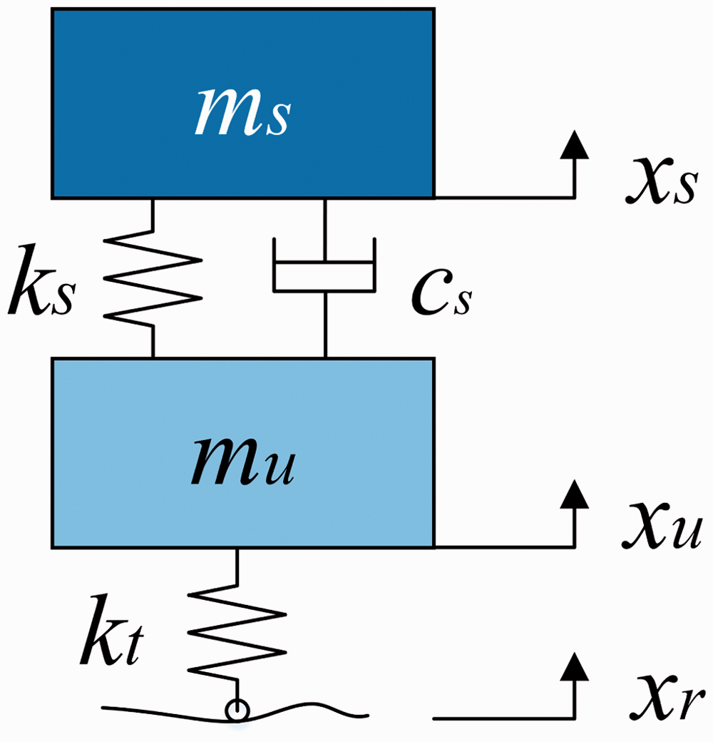
The 2-DOF quarter vehicle model.
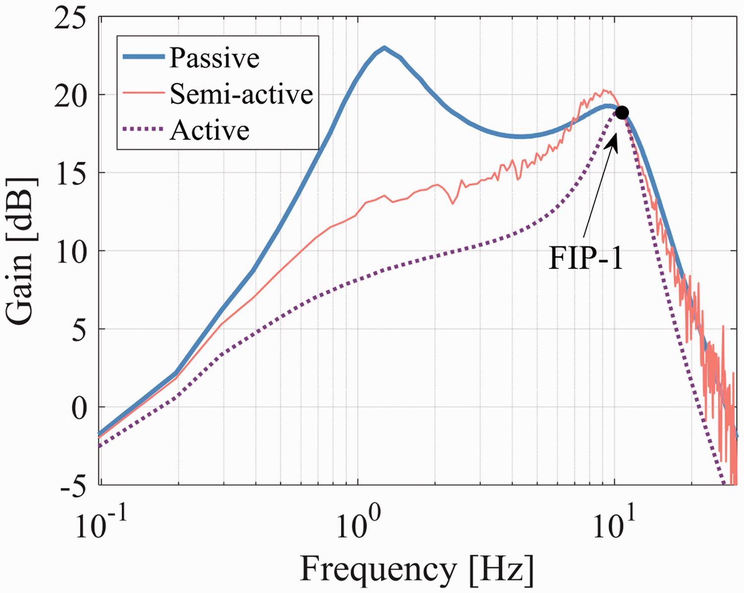
Invariant point of the sprung mass acceleration frequency response.
Modeling and analysis of the quarter vehicle
System modeling
Since the controlled suspensions could hardly eliminate the unsprung adverse effect independently, the TMD is introduced to set a “secondary attack” on the vibrations of the unsprung mass. The quarter vehicle equipped with the TMD is illustrated in Figure 4. In this structure, the mass of TMD (md) essentially acts as a secondary chassis. Different from the original chassis (i.e. the sprung mass ms), the TMD is tuned at a frequency between 8 and 12 Hz, which is generally around the second-order resonance. The well-tuned TMD counters the unexpected vibrations of the unsprung mass by making the same movement in the opposite direction.
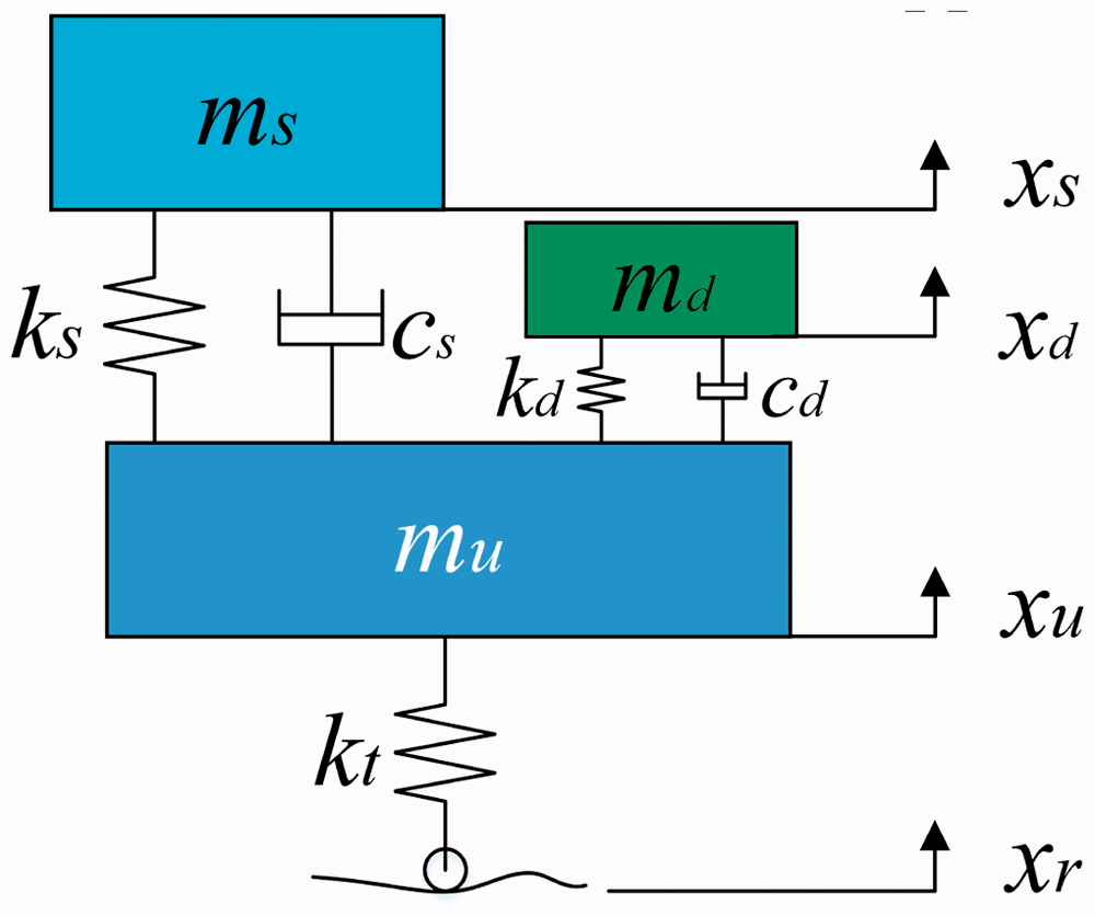
Quarter vehicle equipped with the TMD.
The tire is simplified to a vertical spring kt, while the tire damping is neglected according to Karnopp
31
and Levitt and Zorka.
32
The suspensions of the vehicle and TMD are both constructed with two parts: the spring stiffness (ks, kd) and the shock absorber damping (cs, cd). With the road excitation xr, the sprung mass, the unsprung mass, and the TMD mass generate the vertical motions, xs, xu, xd, respectively. The equations of the vehicle motions can be written as follows


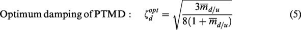
To tune the passive TMD (PTMD), some important parameters are defined as follows
The main topic in this study is to overcome the adverse effect of the weighted wheel. Therefore, the TMD should be tuned to restrain the unsprung mass vibrations around the second-order resonance. According to Den Hartog,
33
the expressions of the frequency and damping of the optimal-tuned PTMD are shown as follows

Invariant property of the combined structure
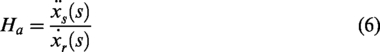
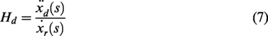
As reviewed above, the invariant point FIP-1 in the 2-DOF vehicle system restricts the performance of the controlled suspension. Hence, the influence of the TMD on the invariant property is of great importance. To explore the influence, the following three important transfer functions are defined
In Hedrick and Butsuen
25
and Karnopp,
31
the invariant frequency and magnitude of FIP-1 are derived as
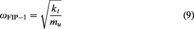
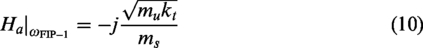
From equations (9) and (10), it can be found that the frequency and magnitude of FIP-1 are independent of the suspension parameters, such as the stiffness ks and damping cs. Hence, the invariant point FIP-1 exists in both controlled and uncontrolled suspensions.
In the 3-DOF vehicle system, the following equation can be obtained by adding equations (1), (2), and (3)

In equation (11), there is no suspension force of any kind, which is similar to the 2-DOF vehicle system introduced in Hedrick and Butsuen
25
and Karnopp.
31
Performing the Laplace transform on equation (11) yields

Then, the following equation can be derived by substituting equations (6) to (8) into equation (12)

When

In equation (14), the 3-DOF vehicle system still shows the invariant property, which couples the motions of the sprung mass and TMD. From equation (14) and (10), it can be found that the invariant magnitude of Ha in the 2-DOF system is shared by two transfer functions (Ha and Hd) after introducing the TMD. The sharing ratio is
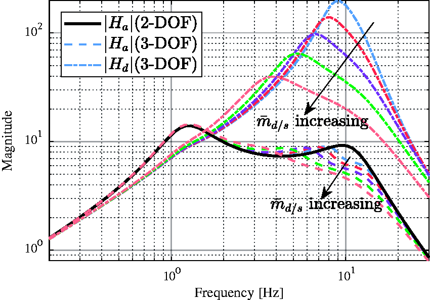
Influence of
Figure 6 shows the relationship between
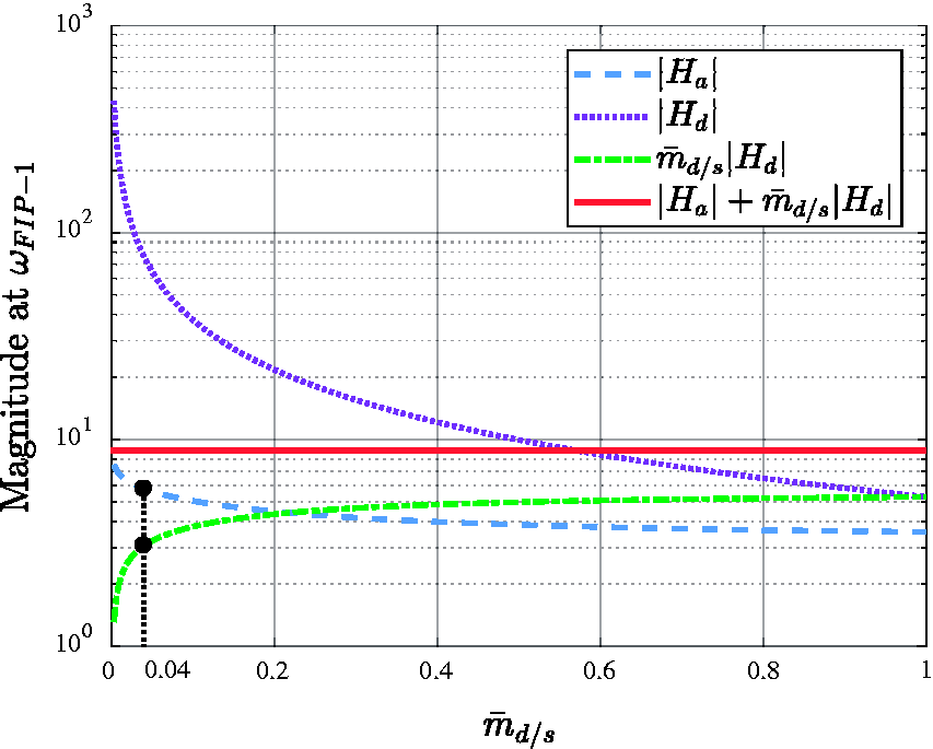
Relationship between
The magnitude of
The magnitudes of
Therefore, considering the working efficiency and lightweight requirements, the mass ratio
Sliding mode control problem formulation
A sliding mode controller (SMC) is designed in this part to eliminate the unsprung adverse effect as well as improve the ride comfort. The control block diagrams are shown in Figure 7, where the diagram of the quarter vehicle without TMD (i.e. the 2-DOF vehicle system) is given in Figure 7(a) and the diagram of the quarter vehicle with TMD (i.e. the 3-DOF vehicle system) is given in Figure 7(b). The sliding mode controller for the 3-DOF vehicle system has two control outputs, in which us and ud correspond to the semi-active suspension and the semi-active TMD (STMD), respectively. The two control outputs are not coupled, so the control output us also suits the 2-DOF vehicle system. Hence, this study only presents the design process of the SMC controller for the 3-DOF vehicle system.
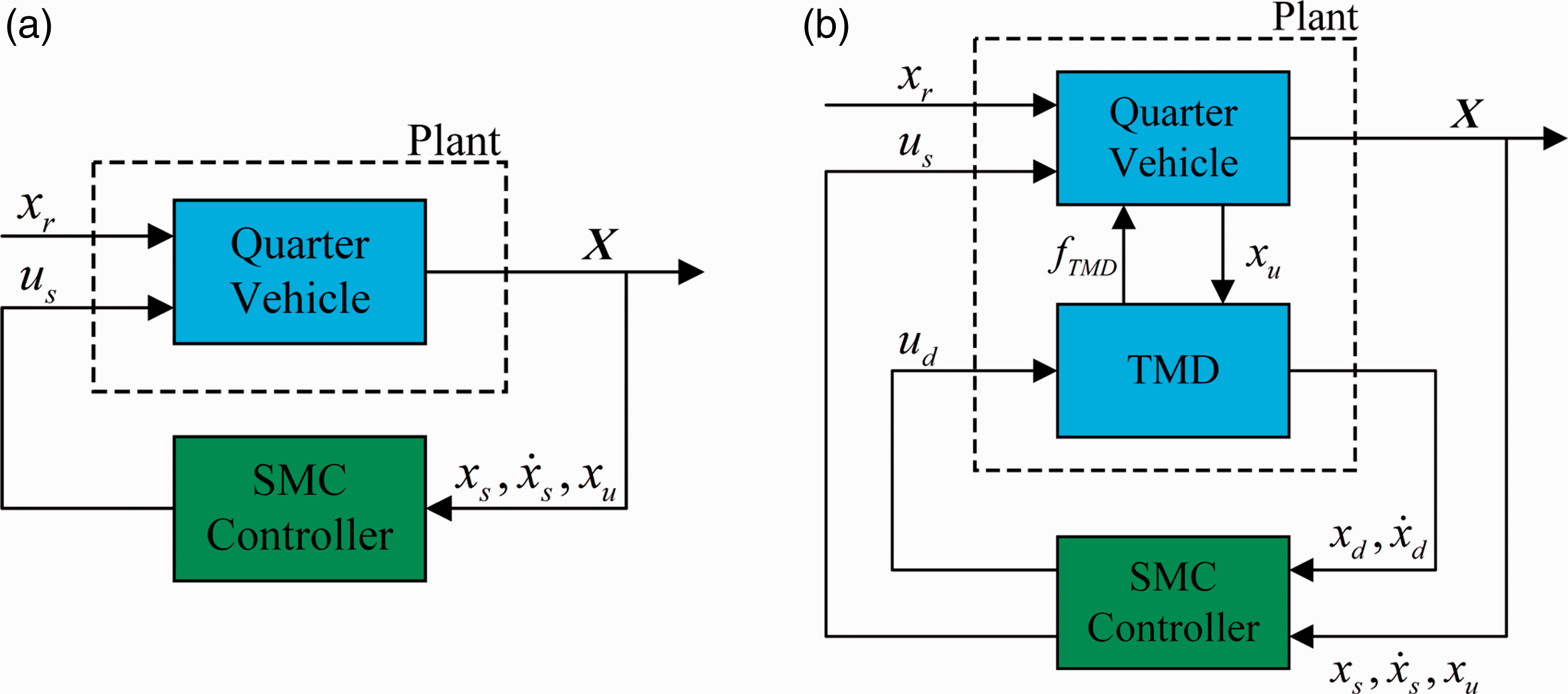
Control block diagrams: (a) 2-DOF system, (b) 3-DOF system.
Equivalent controller
Generally, a conventional vehicle cannot preview the road disturbances forward. Therefore, ignoring the road disturbances, the plant can be described as

The details of the matrices and vectors are attached in Online Appendix A.
Specific tracking error to ride qualities
In order to improve ride qualities and restrain the motion of the TMD simultaneously, the outputs of the plant should be defined as
Then, the tracking error vector can be defined as

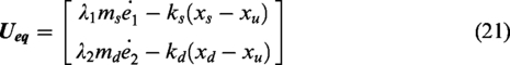
Equivalent controller design
The relative degree n of the controller is defined as 2. Thus, the sliding mode surface can be defined as

The following equation can be obtained by assuming
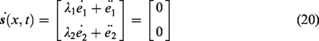
Then, the equivalent control law can be derived from equation (20)
The reaching condition of the sliding mode controller is shown as follows

Then, the following switching control law is chosen to satisfy the reaching condition
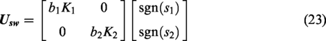
The following sliding mode controller can be obtained by combining the equivalent controller and the switching law

Hence, the controller outputs for the semi-active suspension and STMD can be expressed as follows.
Suspension

STMD

Define the following function as Lyapunov candidate function
Equation (20) can be rewritten as

The following equations can be obtained by submitting the system outputs (
Therefore, the following Lyapunov difference equation is derived

Hence, the presented sliding mode controller is stable.
Inverse model of the controllable damper
In semi-active suspensions, the variable damping is often provided by magnetorheological (MR) dampers,34–36 electrorheological (ER) dampers, 37 and electronic adjustable dampers (EAD). 38 According to the control output, the actuators change the fluid viscosity in MR/ER dampers or the current-controlled area of orifice in variable orifice dampers through the input current. Normally, the control output is the desired damping force. Hence, the relationship between the control output and the input current of the actuator should be built for practical application. In this section, the dynamic model of an EAD is built. Then, the inverse model is derived based on the proposed model.
Modified hysteretic model
A hysteretic model of the MR dampers has been widely studied up until now. Figure 8 illustrates the conceptual configuration of the model. This is a component-wise additive strategy that contains the spring stiffness k, dashpot c, and a hysteretic component α. In this model, the positive direction of velocity
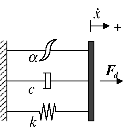
Hysteretic model.
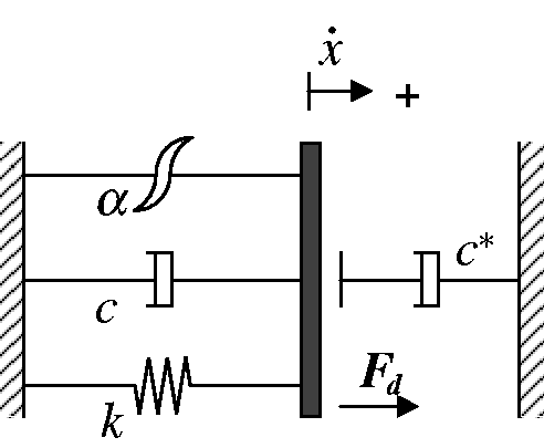
Modified hysteretic model.
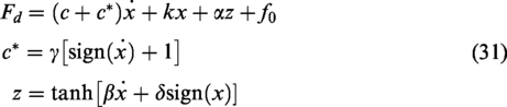
The modified hysteretic model of the EAD could be expressed as
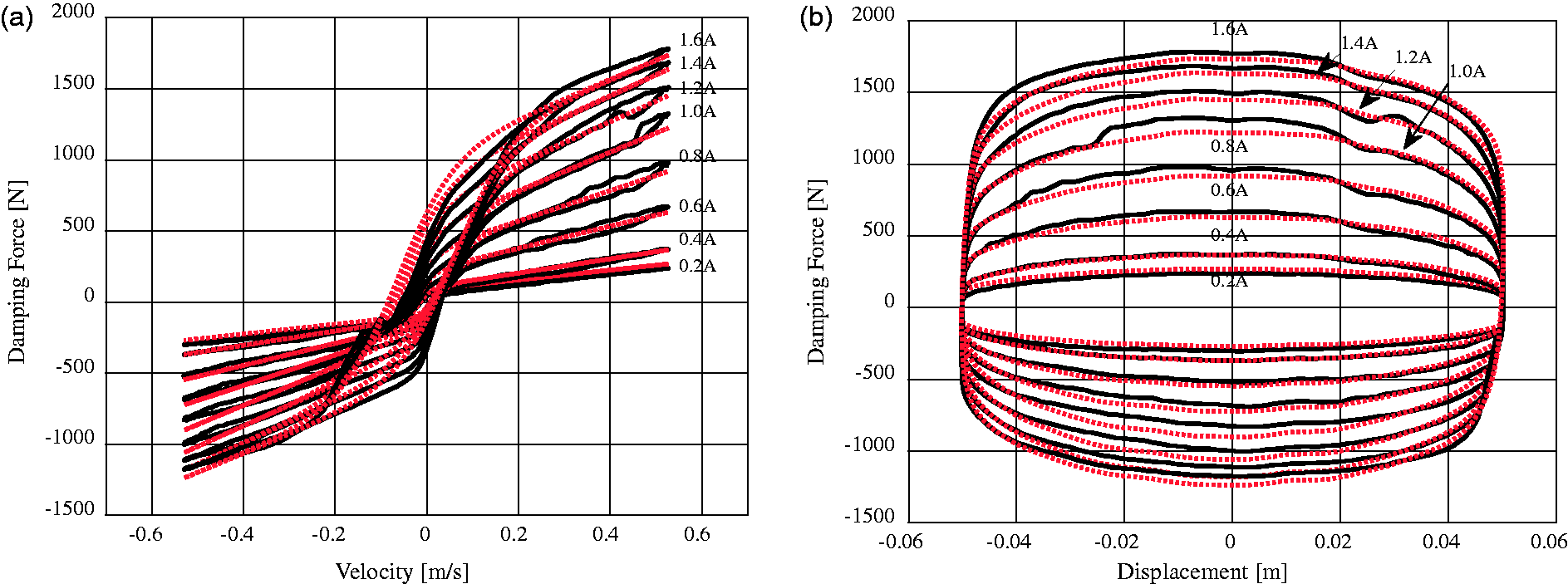
The EAD shown in Figure 10 is employed to generate the semi-active control force in this study. The EAD features an electronically controlled proportional damping valve, which is similar to the continuous damping control damper developed by ZF. 40 The position of the valve changes according to the input current. And the valve’s position reduces or increases the flow of oil through the aperture, adjusting the damping precisely and continuously. The damping property curve of the EAD is fitted through the least squares method. Figure 11 shows the reconstructed damping property curve for the modified hysteretic model. The damping forces obtained from experiments are plotted in solid lines while the model predictions are plotted in dots. As shown in Figure 11, the predicted damping force fits the experiment results well. The proposed model could express the different damping properties of the two strokes as expected.
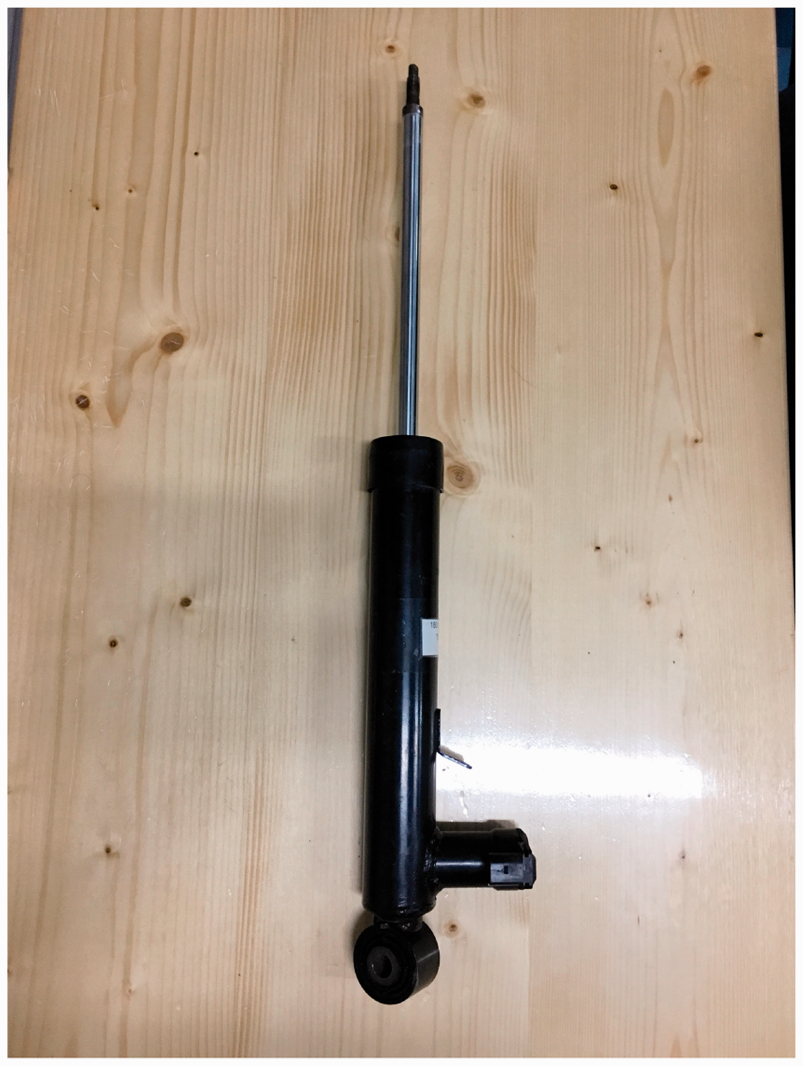
Electronic adjustable damper.
Reconstructed damping property curve from the modified hysteretic model, experiment (black), model (red).
Inverse EAD model
Different experiments are conducted to establish the relationship between parameters
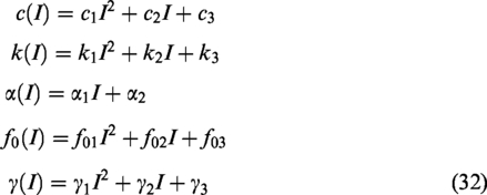
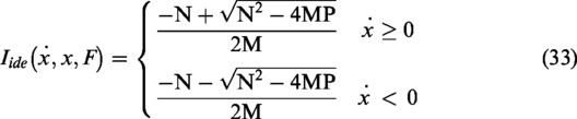
Then, the expression of the input current could be derived by substituting equation (32) into equation (31)
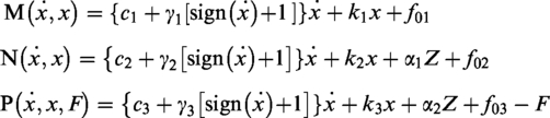
The parameters of equation (32) could be identified with the experiment data. The identified results are shown in Table 1.
Identified parameters.
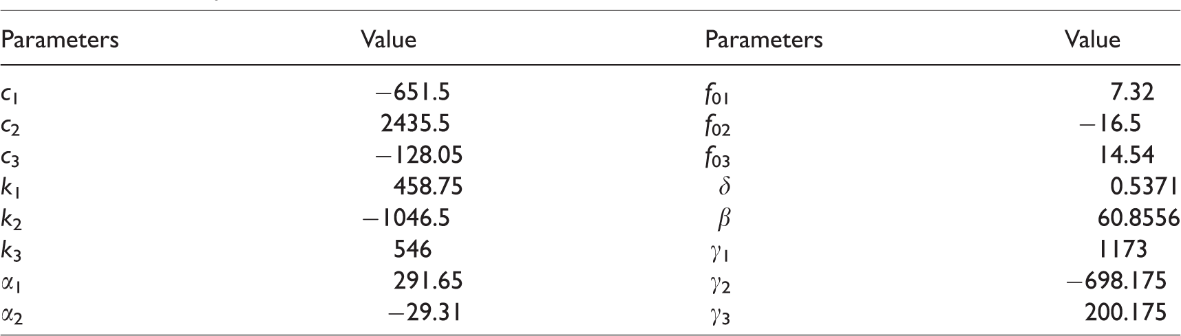
An experiment is conducted to validate the inverse EAD model. The validation method is illustrated in Figure 12. The EAD is tested on shock absorber test rig. During the experiment, the variable current Iexp is applied to the EAD. Sensors are employed to collect damper stroke x, velocity
Evaluation of the inverse EAD model.
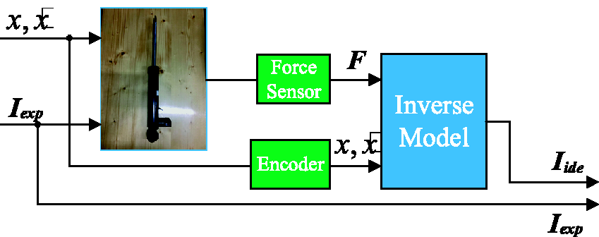
The applied current and calculated current are compared in Figure 13. The two currents almost coincide. The comparison shows that the proposed inverse EAD model has high precision and could be used in the real-time control of the semi-active suspension.
Comparison between experimental and calculated current.
Case study of the quarter vehicle
In this section, the traditional passive suspension (Passive), the passive suspension equipped with the PTMD (ST-Passive), the semi-active suspension (SMA), and the semi-active suspension equipped with the STMD (ST-SMA) are studied. The numerical studies are conducted with Matlab. The bump roads and the random roads are used to validate the suspension performance. The parameters of the studied vehicle can be referred to in Online Appendix B.
The parameters of the SMC controller are selected as shown in Table 2, aiming at eliminating the unsprung adverse effect as well as improving the vehicle dynamic performance.
Parameters of the studied controller.

SMC: sliding mode control.
Bump road
A bump road of 1 m in length and 0.02 m in height is adopted in the simulations to study the transient responses of the vehicles. Two vehicle speeds of 10 km/h and 40 km/h are adopted in the simulations. The time-domain responses of the studied vehicles are shown in Figures 14 and 15.
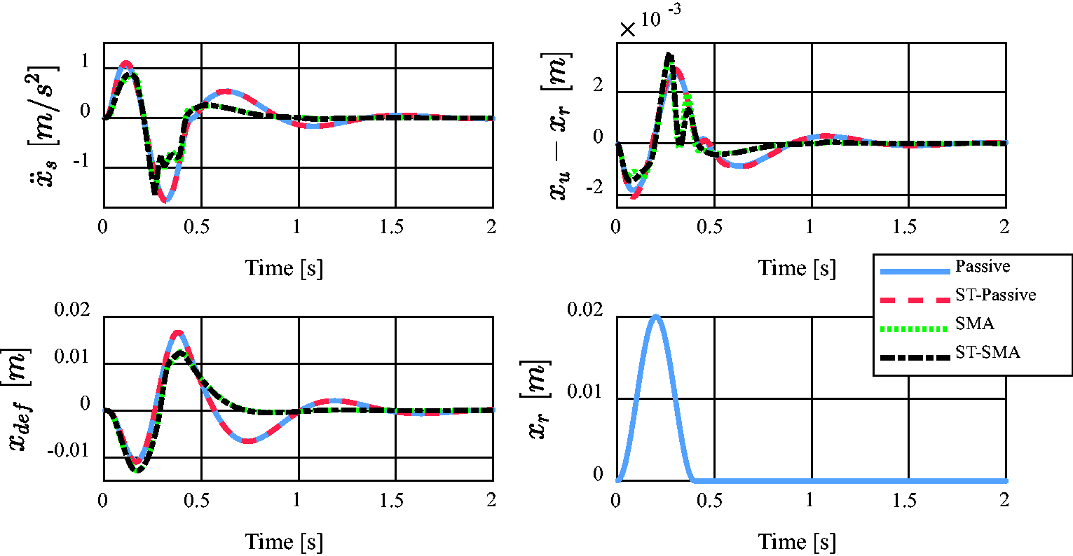
Bump responses of the quarter vehicle (10 km/h).
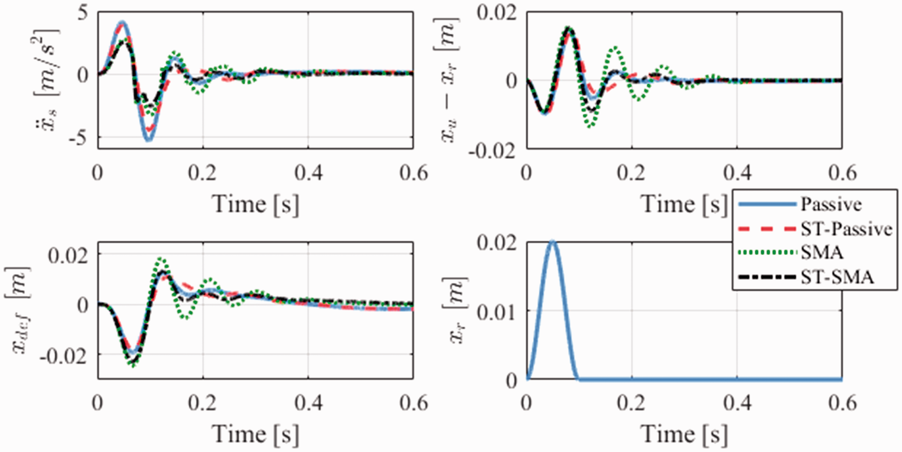
Bump responses of the quarter vehicle (40 km/h).
At the low speed (10 km/h), as shown in Figure 14, Passive and ST-Passive have almost the same response for the three state variables, while SMA and ST-SMA have a little difference in the tire deflection responses at 0.35 s. This phenomenon indicates that the TMD (or STMD) plays a small role at the low speed. In the sprung mass acceleration response, the two controlled systems have remarkable improvements in vibration suppression, especially at the first valley and the second peak. In the tire deflection response, the controlled systems also behave better than the uncontrolled systems. The fluctuations of all the three concerned variables in the controlled systems vanish faster than that in the uncontrolled systems. It shows that the sliding mode controller has significant improvements in the ride comfort and road-holding at low speed. Hence, the semi-active suspension rather than the TMD (or STMD) plays a leading role at this speed.
At high speed (40 km/h), the responses of the studied suspensions are as shown in Figure 15. Comparisons based on the simulation results are conducted as follows.
Passive vs. ST-Passive, SMA vs. ST-SMA
In sprung mass accelerations, ST-Passive and Passive have a similar response before the first valley, and then ST-Passive turns to the smaller magnitudes than Passive. This phenomenon recurs in the controlled systems, which indicates that the TMD (or STMD) can significantly suppress the vibrations of the sprung mass. Similar conclusions can also be drawn from the responses of the tire and suspension deflection.
Passive vs. SMA, ST-Passive vs. ST-SMA
In sprung mass accelerations, SMA significantly reduces the magnitudes of the first peak and valley relative to Passive. Beyond the first valley, the amplitudes and the settling time of SMA are larger than Passive, which is more obvious in the tire and suspension deflection. This situation indicates that the studied controller can improve the vehicle performance partly at this speed.
In conclusion, the TMD and the sliding mode controller both work well at this speed.
As studied in Smith et al.,
41
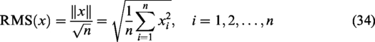
the root mean square (RMS) of the acceleration is strongly correlated with the passenger discomfort. Hence, RMS is adopted for further evaluation. The time-dependent RMS of the concerned variables is defined as
RMS of the concerned variables.
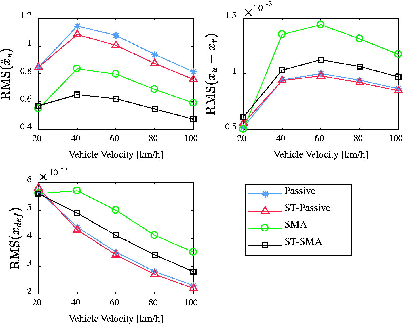
Random road
The C class road excitation is adopted in the random roads simulation, and the vehicle speed is set at 80 km/h. The frequency-domain results are shown in Figure 17. According to equation (4), the resonance frequency of the PTMD is a little smaller than the unsprung mass resonance frequency. Hence, the system vibration energy around the second-order resonance can be absorbed by the PTMD. Consequently, as shown in Figure 17(a), the ST-Passive has better performance than Passive around the second resonance. Meanwhile, the TMD contributes to a new resonance before the second-order resonance of the original system. In other frequency ranges, the ST-Passive behaves the same as Passive, which can also be observed in Figure 17(b). But the new resonance peak before the second-order resonance is more apparent in Figure 17(b), which means that the TMD has a more dramatic impact on the unsprung vibrations than sprung vibrations.
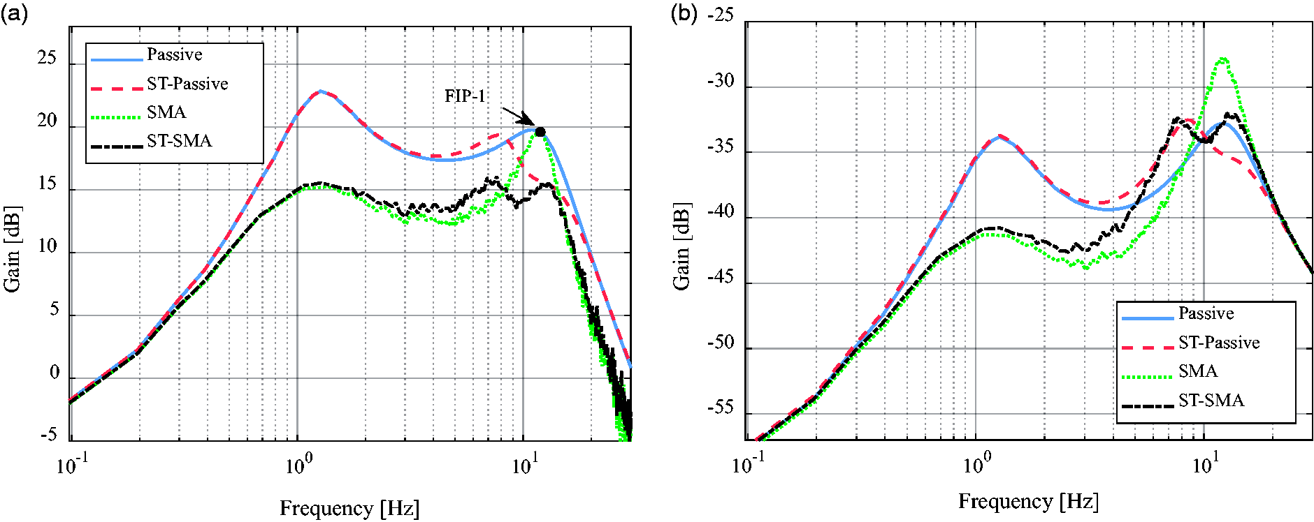
Frequency responses of: (a) sprung mass acceleration; (b) tire deflection.
As shown in Figure 17(a), the SMA and ST-SMA both have remarkable improvements on the sprung mass accelerations around the first-order resonance. Without the constraint of the invariant point, ST-SMA can improve ride qualities more effectively around the second-order resonance, in comparison to SMA. Apparently, the unsprung adverse effect can be eliminated with ST-SMA. Consequently, a remarkable improvement of ride comfort can be obtained with ST-SMA in the whole frequency range.
As for the tire deflection, SMA and ST-SMA have similar suppressing effects at the first-order resonance, as shown in Figure 17(b). Around the second-order resonance, large gains appear in SMA, which is bad for the road-holding. However, the second-order resonance of ST-SMA is suppressed to some extent with the introduction of STMD.
The normalized RMS is adopted as the performance criteria under the random roads, which is defined as follows

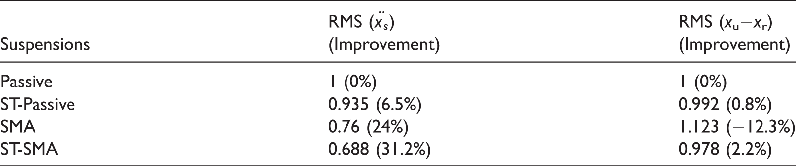
The comfort and road-holding trade-offs for different suspensions are shown in Figure 18. The damping of Passive is tuned to obtain a balanced performance between the ride comfort and road-holding. ST-Passive shows an improvement in both the performances. The comfort index of SMA is much smaller than that of Passive, while the road-holding index is much larger than that of Passive. As for ST-SMA, both of the two indices are smaller than the other three suspensions. This phenomenon indicates that ST-SMA can improve both the ride comfort and road-holding. The normalized RMS of the sprung mass acceleration and tire deflection are shown in Table 3. By comparing the values, it is easy to see that ST-SMA can improve the ride comfort by 31.2% and road-holding by 2.2%. Hence, the proposed method can achieve great improvements in the vehicle vertical dynamics performance.
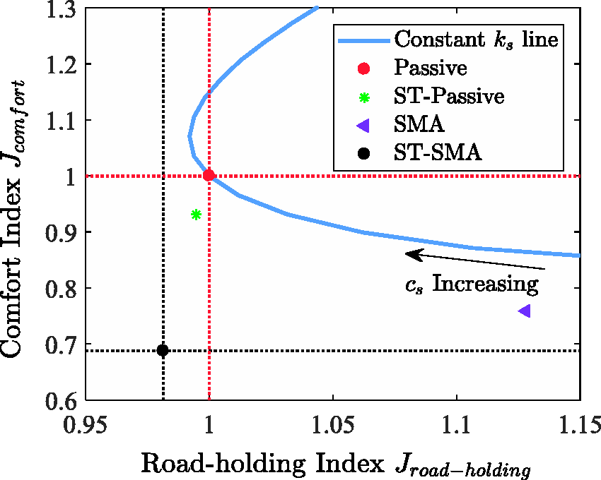
The comfort and road-holding trade-offs for different suspensions.
The performances of the studied suspensions under the random road disturbances.
Hardware-in-the-loop simulation
In practice, the performance of semi-active suspensions can be influenced by the nonlinear characteristics of the damping force, the dynamics of solenoid valves, the time-delay of the control system, and so on.28,42 Hence, the hardware-in-the-loop simulation with a real damper and a control system is developed to validate the controller in the presence of nonlinearities. The configuration for the HILS is shown in Figure 19. The relative velocity between the sprung mass and the unsprung mass is simulated by a damper test rig. Matlab® is chosen as the computer-aided tool to provide a programming environment. National Instrument® PCI-6229 data acquisition board is utilized as a rapid control prototyping tool to implement the vehicle model. The EAD modeled in the previous section is employed to generate the semi-active control force. Arduino® Mega microcontroller is employed as an ECU to host the sliding mode control algorithm. A damper driver is designed to supply current to the EAD according to the control voltage from the ECU. The feedback variables including the damper force and the suspension deflection are measured respectively by Interface® 1210AF load cell and Maglin® linear magnetic encoder.
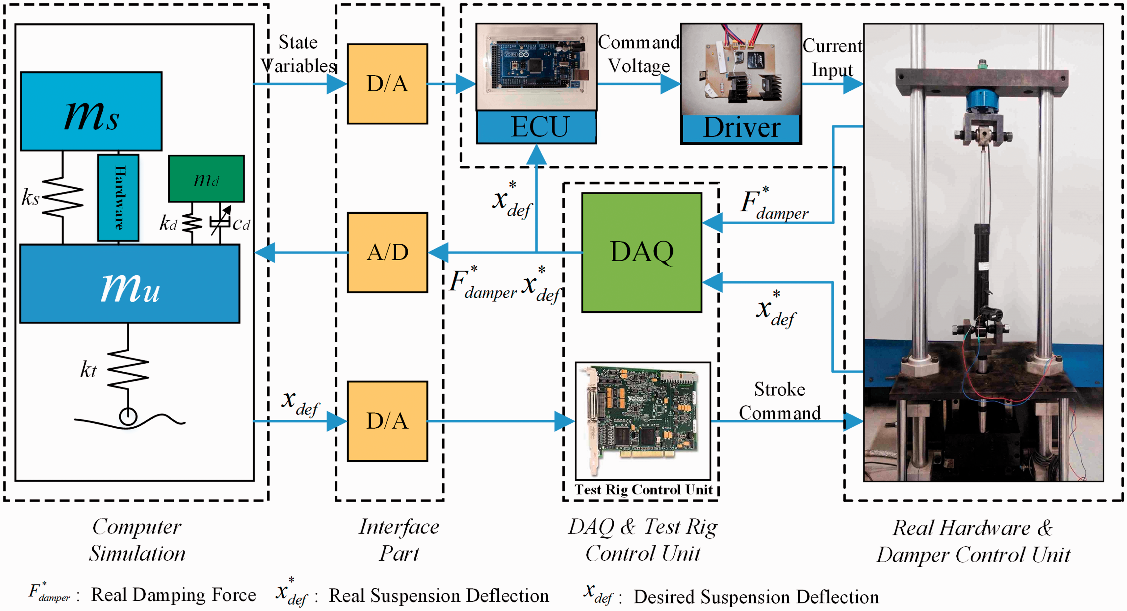
Schematic diagram of HILS.
The velocity–force property of the EAD is shown in Figure 11. The EAD shows an obvious hysteresis property at a certain current. The damping forces are proportional to the applied currents, except at 0 A, which is designed for the power-off protection. The currents of 0.2 A and 1.6A are respectively adopted to provide the minimum damping csmin and the maximum damping csmax according to the parameters in Online Appendix B.
The road condition with the HILS adopts the bump road presented above. The sampling time is set to 0.005 s. The vehicle speed is set as 10 km/h to validate the controller, since the semi-active suspension rather than the STMD plays a leading role at a low speed.
As shown in Figure 20, ST-SMA shows remarkable advantages over Passive in the vibration suppression, which is similar to the simulation results in Figure 14. Although the linear damping csmin and csmax are replaced by a real damper, the sliding mode controller also behaves in the numerical simulations.
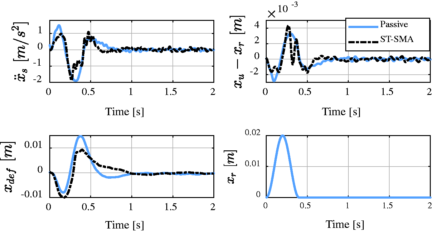
HILS bump responses of the quarter vehicle (10 km/h).
Case study of the full car
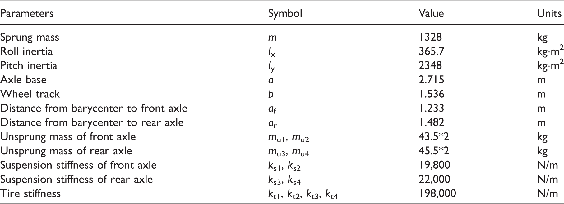
To validate the effect of the proposed method, a full car is modeled with STMD. The 11-DOF model is shown in Figure 21. The red parts are the STMDs, which are named as TMD1, TMD2, TMD3, and TMD4 corresponding to left-front, right-front, left-rear, and right-rear, respectively. The roll and pitch angle of the vehicle body are signified with ϕ and θ, respectively. Other parameters of the full car model are shown in Table 4. The four corners of the full car are controlled independently and the controller parameters are the same as that of Table 2. In the full car study, the proposed ST-SMA suspension is compared with two classical semi-active suspensions, sky-hook 16 and mixed sky-hook and ADD (SH-ADD). 43
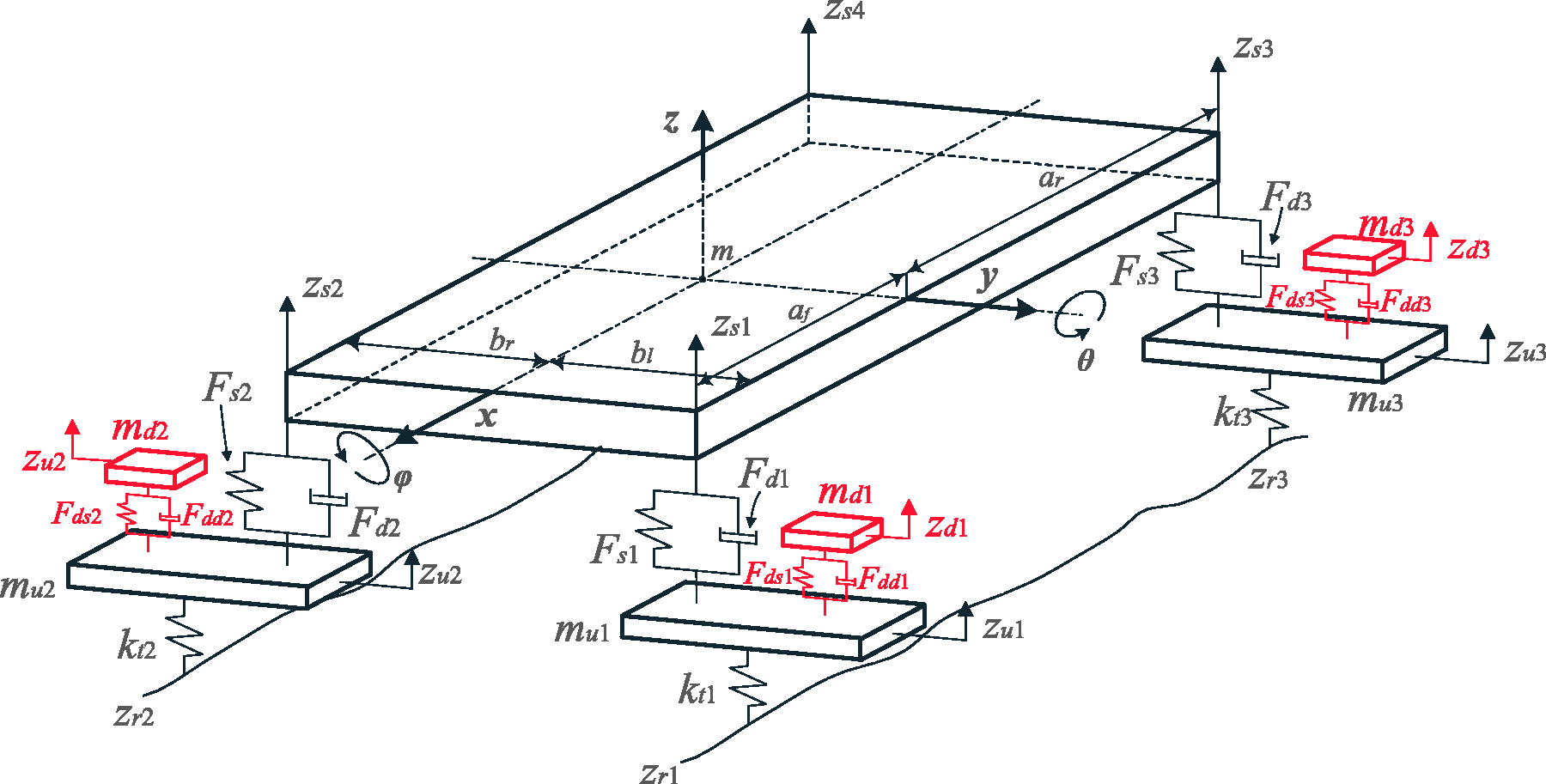
Full car model with STMDs.
Parameters of the full car model.
Bump road
The bump road introduced in an earlier section is adopted in the full car study. The excitations at the left and right wheels are the same. The bump road excitation at a vehicle speed of 40 km/h is shown in Figure 22.
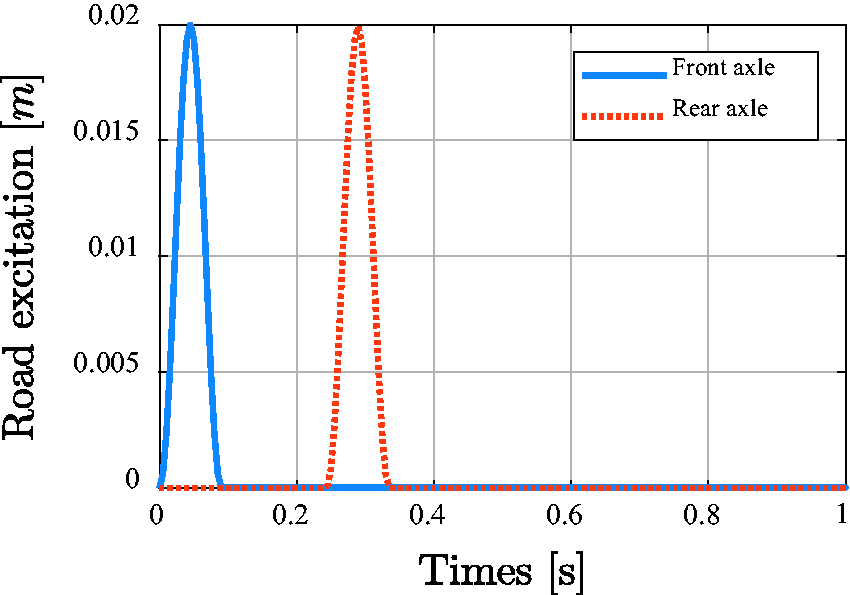
The bump road excitation.
The simulation results in the time-domain are shown in Figure 23. The four figures involve sprung mass acceleration, pitch rate, left-front tire deflection, and left-front suspension deflection. Because of the same excitation between left and right track, the full car has no roll motion. As shown in Figure 23, the control effect of sky-hook is not as good as other suspensions. The sky-hook control algorithm has a good performance at low frequencies. When the vehicle rides through the bump road at a speed of 40 km/h, the excitation frequency is up to 11 Hz, which is beyond the effective frequency band of sky-hook. But the pitch rate decreases obviously at the control of sky-hook. The SH-ADD suspension effectively controls the sprung mass acceleration and pitch rate. Regarding the ST-SMA suspension, there are substantial improvements in the sprung mass acceleration and pitch rate, which means good ride comfort. The tire deflection of ST-SMA is similar to the passive suspension, which is better than the other semi-active suspensions. The suspension deflection has a very small fluctuation during the whole simulation time, which are the obvious advantages of ST-SMA.
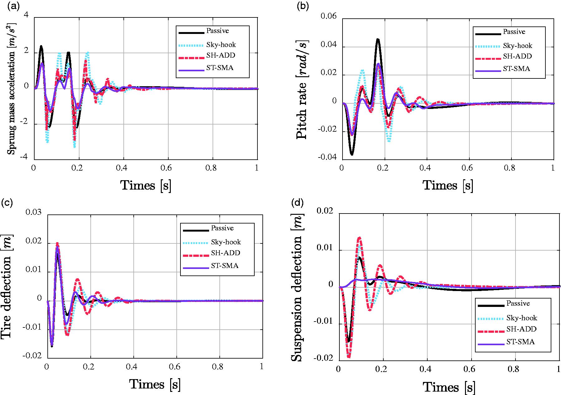
Time-domain response at the bump road: (a) sprung mass acceleration; (b) pitch rate; (c) tire deflection; (d) suspension deflection.
The normalized RMS of different parameters is shown in Figure 24. At a speed of 40 km/h, sky-hook suspension has a good performance in the chassis attitude control. SH-ADD suspension could improve both chassis vibration and attitude. Regarding the ST-SMA suspension, there are great improvements in the chassis vibration, chassis attitude, and suspension deflection. In addition, the tire deflection of the ST-SMA suspension has better performance than other semi-active suspensions, even though there is deterioration.
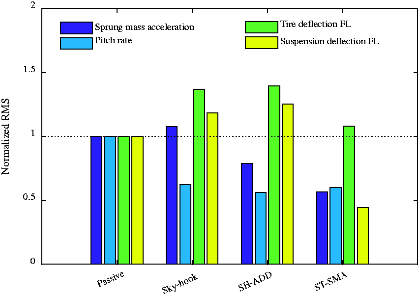
Normalized RMS of different parameters (40 km/h).
Random road
The C class road excitation is adopted for the full car simulation. Figure 25 shows the road excitation at the four wheels. The simulation time is set to 100 s. The vehicle speed at each simulation cycle is constant.
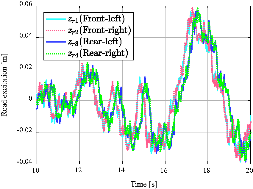
Random road excitation at the four wheels.
Figure 26 shows the RMS values of the passive, SH-ADD, and ST-SMA suspensions at different vehicle speeds. The six figures involve the parameters of the sprung mass acceleration (
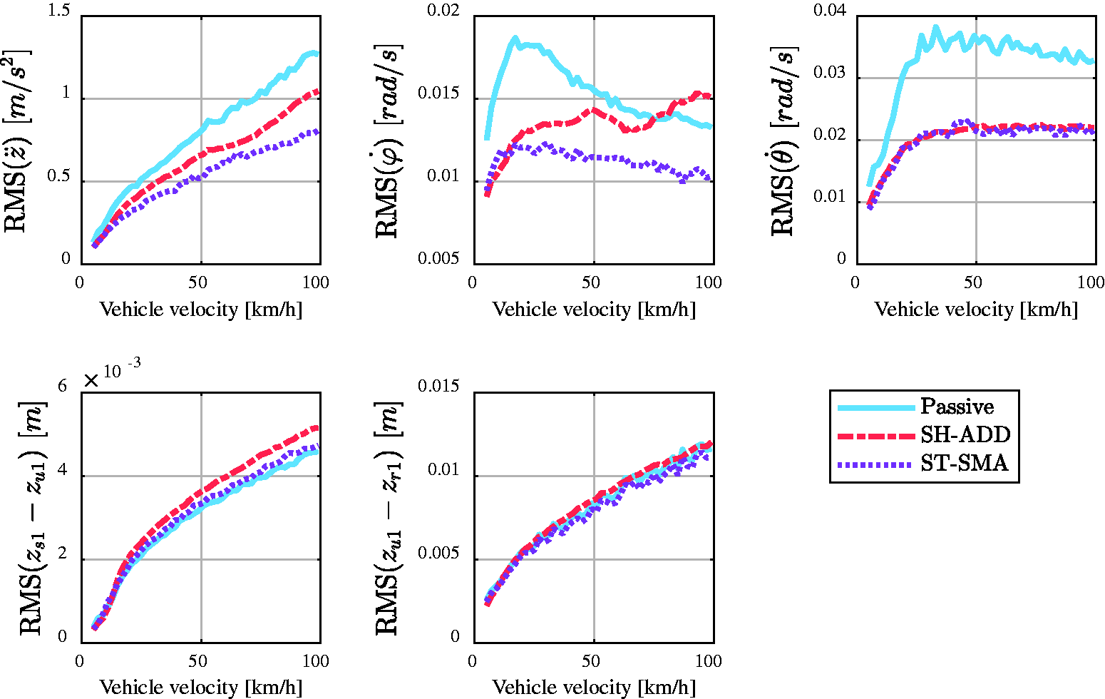
RMS values at different speeds.
Conclusions
This paper studies a combined structure to eliminate the unsprung adverse effect of IEVs, which is constituted by a controlled suspension and a controlled TMD. Among them, the controlled TMD is attached to the unsprung mass to eliminate the constraint of the invariant point. A sliding mode controller is designed for both the suspension and the TMD to eliminate the unsprung adverse effect as well as improve the ride comfort.
The beneficial performance of the combined structure can be concluded as follows:
The invariant property of the combined structure couples the motions of the sprung mass and TMD. The vibrations of the sprung mass can be suppressed by increasing the weight of the TMD. However, a large weight does not mean a high efficiency in vibration suppression. Hence, a proper weight of TMD should be chosen considering the design constraints and the working efficiency. In the bump roads, the semi-active suspension of the combined structure plays a leading role at low speed. As a result, both the ride comfort and road-holding can be improved. At high speed, the semi-active suspension and the controlled TMD work simultaneously to improve ride comfort by little compromise on the road-holding performance. On random roads, the combined structure shows no invariant point at the unsprung resonance frequency. The unsprung adverse effect can be eliminated completely by combining the structure with the sliding mode controller. Furthermore, the ride comfort can be improved across the whole frequency spectrum. In addition, the road-holding can also be obviously improved in low frequencies. In detail, the proposed method can improve the ride comfort by 31.2% and road-holding by 2.2%. In the full car simulation, the proposed method shows good performances in vibration control. The chassis vibration and attitude could be obviously improved. Meanwhile, the tire deflection and suspension deflection are similar to that of the passive suspension. The proposed ST-SMA could eliminate the unsprung adverse effect of IEVs to a certain extent.
Supplemental Material
Supplemental material for A method to eliminate unsprung adverse effect of in-wheel motor-driven vehicles
Supplemental material for A method to eliminate unsprung adverse effect of in-wheel motor-driven vehicles by Shida Nie, Ye Zhuang, Fan Chen, Yong Wang and Shu Liu in Journal of Low Frequency Noise, Vibration and Active Control
Footnotes
Declaration of conflicting interests
The author(s) declared no potential conflicts of interest with respect to the research, authorship, and/or publication of this article.
Funding
The author(s) disclosed receipt of the following financial support for the research, authorship, and/or publication of this article: The work was supported by China Automobile Industry Innovation and Development Joint Fund (No. U1664257).
References
Supplementary Material
Please find the following supplemental material available below.
For Open Access articles published under a Creative Commons License, all supplemental material carries the same license as the article it is associated with.
For non-Open Access articles published, all supplemental material carries a non-exclusive license, and permission requests for re-use of supplemental material or any part of supplemental material shall be sent directly to the copyright owner as specified in the copyright notice associated with the article.