
Abstract
The damping characteristic of a healthy limb changes throughout the gait cycle. However, for amputees who are wearing mechanically passive damping prosthesis, the lack of ability to change the damping values might expose them to injuries and health problems. The use of magnetorheological fluid damper in prosthetic limb, which provides wide dynamic range, seems to be able to prevent these conditions from happening, due to its response to the magnetic field. The magnetorheological fluid, a type of smart material that is capable of altering its rheological property, changes its viscosity subjected to the intensity of the external magnetic field. Thus, due to this property, magnetorheological fluid damper covers the advantages of both passive and active dampers. This work explores the implementation of magnetorheological fluid damper in transtibial (below knee) prosthetic limb utilizing adaptive control techniques via simulation studies. An experimental study was done to observe the relationship of the force generated by the damper to the applied current. In addition, fuzzy-proportional–integral–derivative controller was implemented to ensure that the damper performs well, even at varying frequencies.
Introduction
Variable damping mechanism is widely adopted in mechanical designs as compared to passive damping mechanism due to its wide dynamic range. One of the methods to implement variable damping is to use magnetorheological fluid (MRF). MRF is a smart material in the form of a liquid that contains magnetic particles and reacts to a magnetic field. With the presence of magnetic field, the magnetic particles inside the fluid will arrange themselves into chain-like structures, and thus, creating resistance to the flow. The value of the generated force is highly dependent on the magnetic field, which is induced by the current flowing through the coils that circulate the piston. This behaviour makes it useful in many applications including, but not limited to, seismic applications,1,2 disc brakes,3,4 vehicle seat suspensions5–7 and rehabilitation devices.8–10
In the area of transtibial prostheses, one of the main concerns in selecting a prosthesis is the degree of shock absorption, which refers to how much of the impact during stance phase can be dissipated. In addition, throughout the gait cycle, in a healthy human limb, shock absorption is provided by the muscle, which dissipates mechanical energy through the lengthening of the muscles.11,12 The elastic arc at ground contact also serves as a shock absorber. 13 Thus, adding damping components to the prosthetic limb is crucial to reduce injuries and give comfort to the amputees.14–16 Furthermore, it is capable of protecting other joints and parts mounted to the prosthesis.
As a person walks through the gait cycle, the amount of damping force needed varies based on the flexion angles and other forces. It is no doubt that active or microprocessor controlled prosthesis shows the best performance as it is capable of tuning the amount of damping force automatically. Studies to compare the effectiveness of powered prosthesis have also been done.17–20 However, this kind of prostheses is normally twice the weight and higher in cost. In addition, in active systems, the risk of system instability might occur. 21 Due to this reason, most of the amputees opt for SACH (solid ankle-cushion heel) foot, at which, the damping effect comes from the cushion heel. Another better option is the energy storing foot (such as Össur flex-foot Cheetah and Endolite Epirus), which uses passive elastic materials that enable amputees to participate in daily activities. Hence, to capture the advantages of a passive damper, along with to perform as good as an active damper, semi active damper is adopted in the design of prosthetic limb in this research.
In this work, magnetorheological fluid (MRF) damper was opted to be implemented in the transtibial prosthetic limb. The amount of applied current, frequency as well as stroke length contribute to the level of damping force. Thus, it is important to implement an adaptive controller so that the damper performs well at varying frequency. PI controller, 22 feedback linearization, 23 sliding mode tracking control, 24 fuzzy logic controller, 25 and neural network 26 are among the adaptive controllers that are used in lower limb prosthetic limb. All of these works produced satisfactory results, based on their respective objectives. In addition, the use of adaptive control is proven to be better in obtaining the response of the system. 24 Hence, in this paper, the use of fuzzy-proportional–integral–derivative (F-PID) controller is introduced.
This paper describes the use of magnetorheological fluid damper in transtibial prosthetic limb. The work is initiated by obtaining the force response of the MRF damper experimentally. A controller is then designed so that the system is capable of reducing vibrations at various frequencies. The collected data are integrated into the system in the form of a look-up table.
Simulation of human walking using MATLAB Simulink
Human gait cycle comprises of two main phases which are stance phase and swing phase. Stance phase, which occurs around 60% of the normal human walking cycle, is the moment at which the foot is in contact with the ground whereas swing phase refers to the period when the foot is in the air. The gait cycle can be further classified into eight phases based on the knee motion and angular velocity. 27 These phases are initial contact (heel strike), loading response, mid-stance, terminal stance, pre-swing, initial swing (toe-off), mid swing and terminal swing (Figure 1).
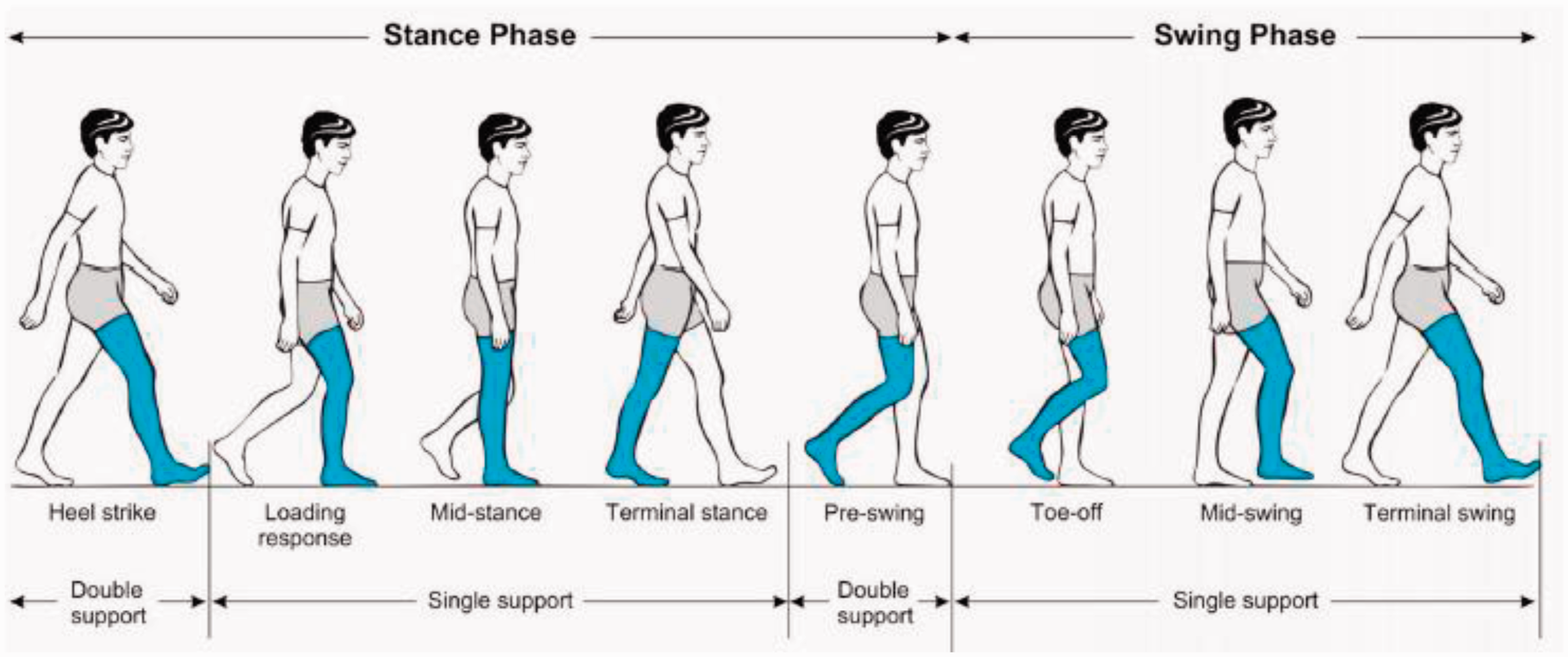
Human gait cycle. 28
In deriving the mathematical modelling of human lower limb, the leg was represented as a linkage system, pivoting at the hip joint. Two links were used to represent the thigh and shank, and the foot was modelled as a triangular foot (Figure 2).
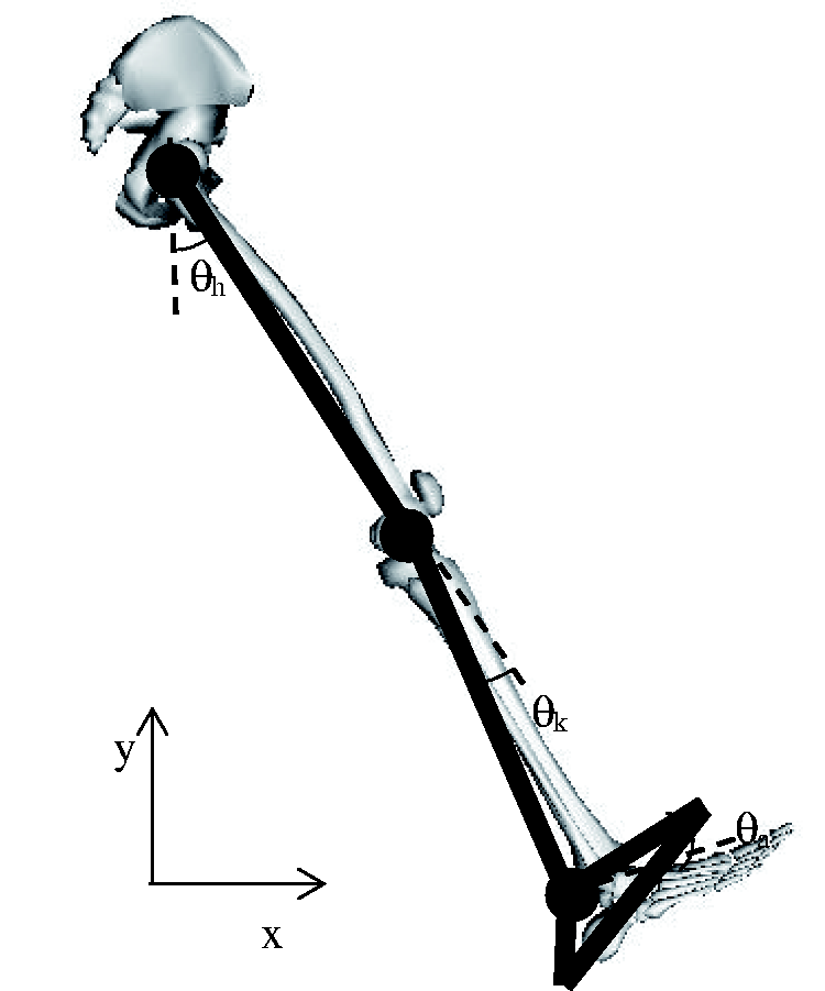
Link-segment model (thigh, shank and foot) for a single human leg (model taken from OpenSim 3.2).
Based on Figure 2, the hip, knee and ankle flexion angles used are represented as θh, θk and θa respectively. θh is taken as the angle between the thigh to the vertical line; where positive hip angle represents hip flexion, and negative hip angle refers to hip extension. θk is measured from the position of the shank to the straight line extended from the thigh with positive knee angle describes the knee extension and negative knee angle is the knee flexion. On the other hand, the degree of the foot rotates around its ankle is represented by θa, at which, plantar flexion is represented by positive ankle angle and negative ankle angle depicts dorsiflexion.
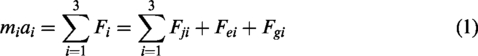
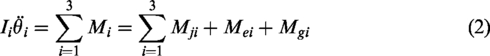
Generally, the equations of motion of i-th human lower limb segment can be expressed as
The free body diagram of the thigh, shank and foot, in the form of a linkage system, is illustrated in Figure 3.
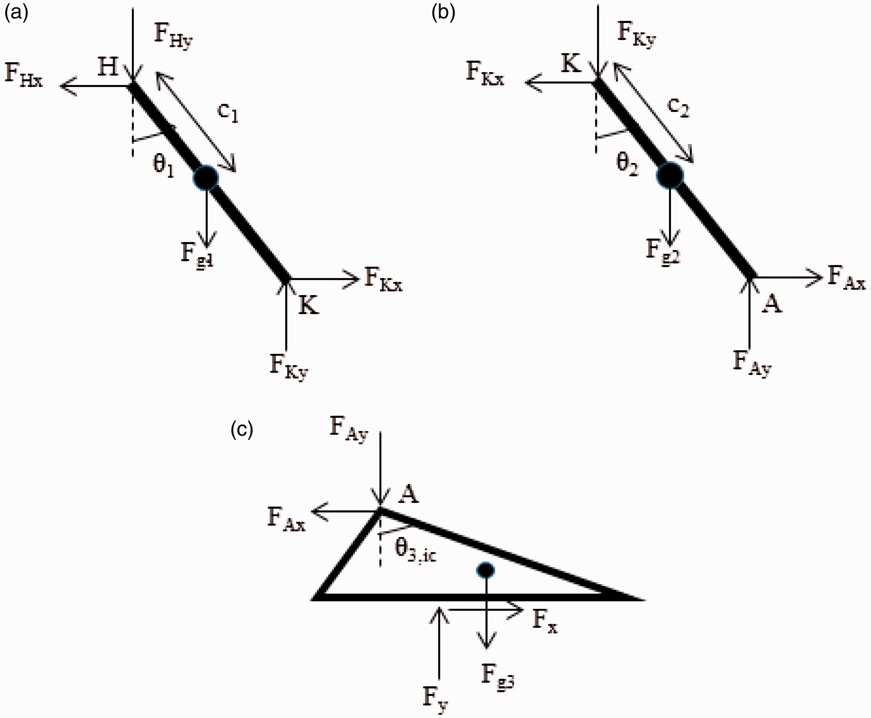
External forces acting on (a) thigh (b) shank and (c) foot.
From Figure 3, the values of θ1, θ2 and θ3 define the angle of the link with respect to the vertical axis. Subscripts 1, 2 and 3 refer to the thigh, shank and foot. In terms of θh, θk and θa, they can be expressed in equations (3) to (5)


The reaction forces at each joint, due to the external forces, are described as
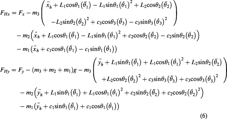
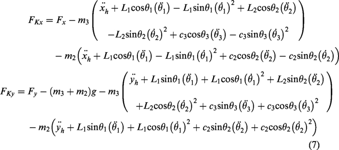
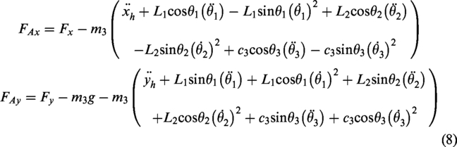
In the above equations, L is the length, m is the mass and c is the distance from the centre of mass to the joint.
On the other hand, moments around joints, M as induced by the external forces are
29


In this article, the simulation of human walking was done in MATLAB Simscape Multibody. In the simulation studies, the hip was grounded.
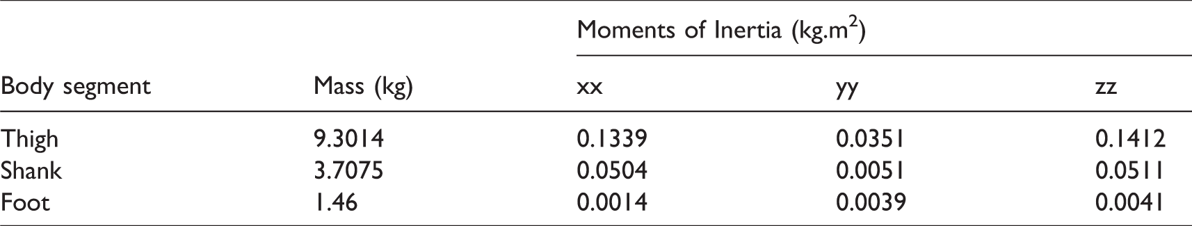
The inertial parameters used in the simulation were obtained from OpenSim, which is an open source software that is used to study neuromusculoskeletal system. The parameters involved are listed in Table 1.
Inertial parameters used, obtained from OpenSim Gait 2392 model.
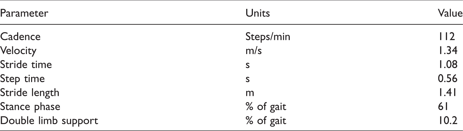
In addition, the temporal and distance variables are listed in Table 2. Temporal variables refer to the stance time, single limb and double support time, stride time, step time, cadence and speed. On the other hand, distance variables describe stride length, step length and step width. 31 Figure 5 shows the associated position of the links, which mimics human walking, with the flexion angle (Figure 4) as an input. The trajectory of the joints can also be seen in Figure 5.
Parameters used in simulation. 30
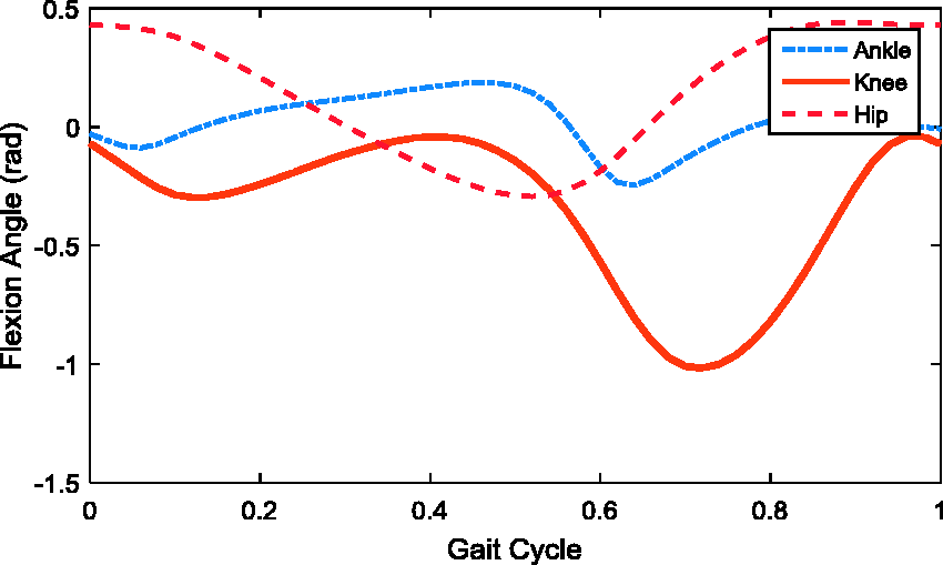
Flexion angles of human lower limb, taken from OpenSim.
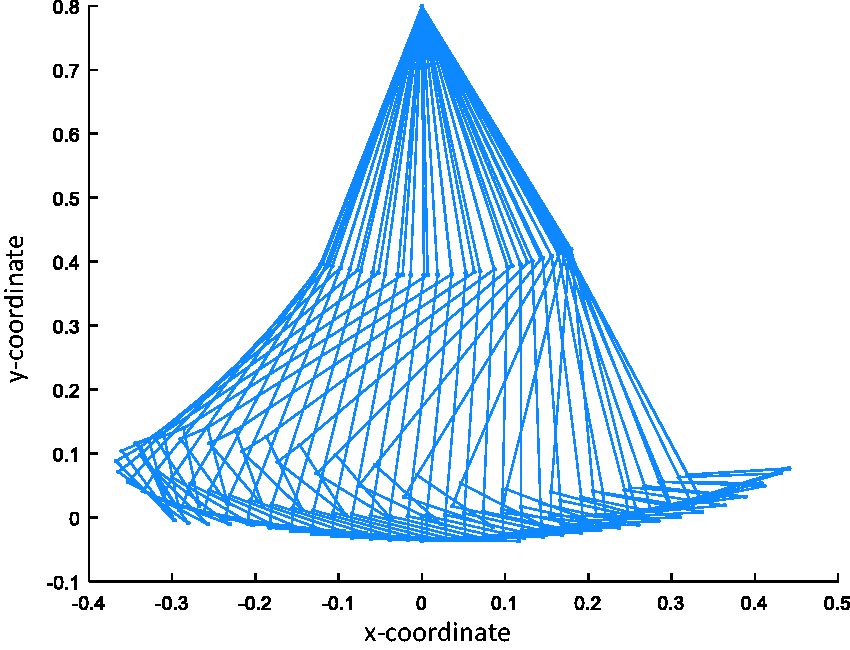
Simulation of human walking, grounded at hip joint.
Magnetorheological fluid damper in prosthetic limb
In this work, the behaviour of the MRF damper was first studied through experiment. Upon obtaining the experimental data, a suitable controller for the prosthetic limb was then designed.
Experimental studies to obtain the response of MRF damper under different magnetic field
In order to observe the response of the damper with respect to the applied current, an experiment utilizing a universal testing machine (UTM) and the magnetorheological fluid damper itself was conducted. The MRF damper (LORD RD-8041–1) was placed in between the grips of a UTM, as in Figure 6. The range of displacement considered in the experiment was from 0 mm to 15 mm for both tensile and compression modes, with the piston moving at a speed of 30 π mm/s. The applied current varied from 0 A until 1 A, with an increment of 0.1 A.
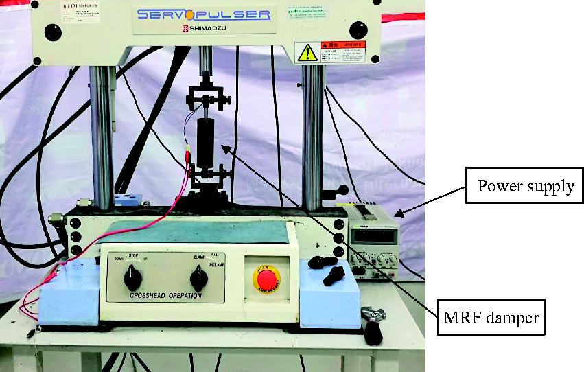
MRF damper experimental setup.
In general, it is seen in Figure 7 that as the applied current increases, the force from the damper increases as well; with the force at off-state (0 A) being the lowest. This is because, without the magnetic field, there is no magnetic interaction between the particles and thus, the fluid is free to flow. On the other hand, parallel chains formed by the particles through magnetic interaction restrict the movement of the fluid which directly gives resistance to the fluid flow. The stronger the magnetic field, the stronger the chain, and thus, different amount of current produces different amount of force. Thus, the damping force generated by the MRF damper can be tuned, through controlling the amount of current applied, which makes it usable in wide applications.
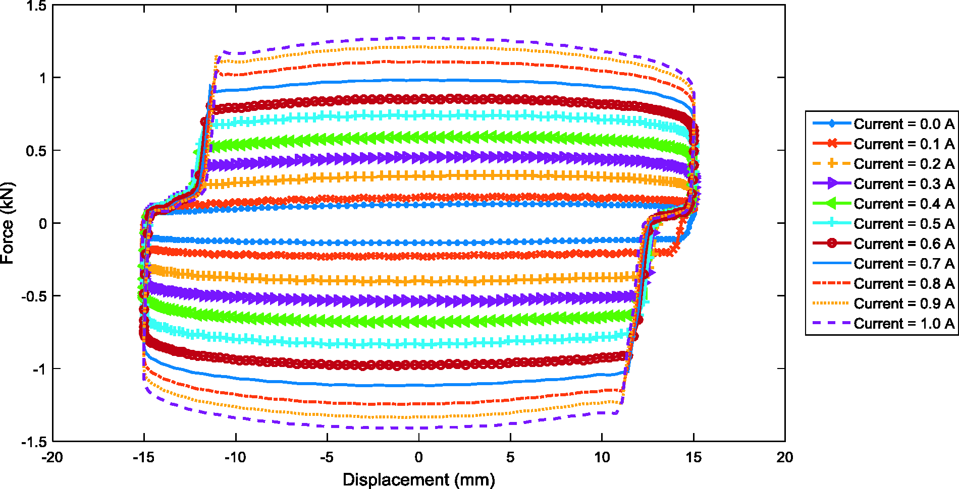
The force–displacement graph of the MRF damper used in the experiment.
Vibration control of MRF damper
To study the effect of adding a damper to the prosthetic limb, a simulation study to model the transtibial prosthetic limb was carried out. The attachment of the damper to the knee and the heel, in parallel to a spring with constant k is shown in Figure 8. At this stage, the use of motor was not considered in the calculation. It was also assumed that the impact occurs during heel strike, which was assumed in the form of impulse signal, needs to be attenuated. This is because shock absorption during heel strike is important as foot stops abruptly during this phase. The associated free body diagram of the model is displayed in Figure 9.
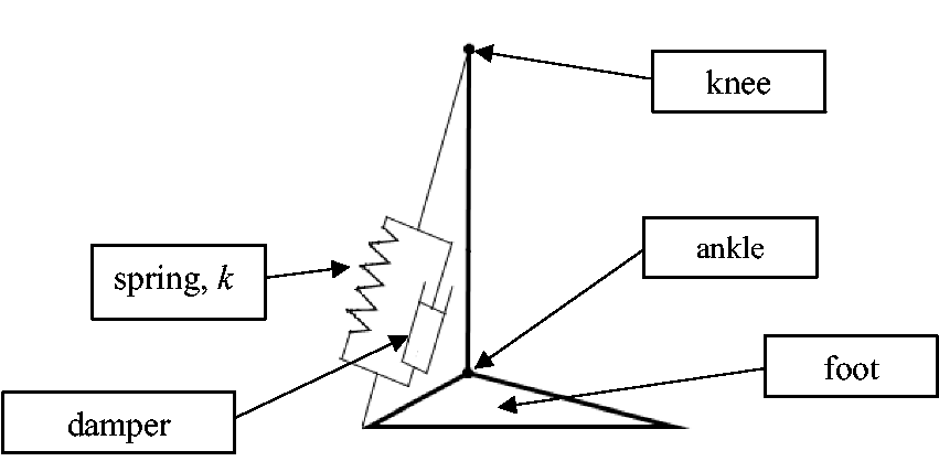
Simplified model of transtibial prosthetic limb with linear MRF damper.
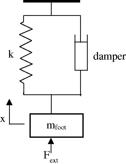
Free body diagram of transtibial prosthetic limb with MRF damper.
The equations governing the model can be expressed as


In general, the control system block diagram of MRF damper in transtibial prosthetic limb is shown in Figure 10. In this section, only system controller was studied. To represent the process represented by ‘Damper controller’ and ‘MRF damper’ blocks, a look-up table is used in the simulation. The look-up table contains experimental data, which was done earlier.
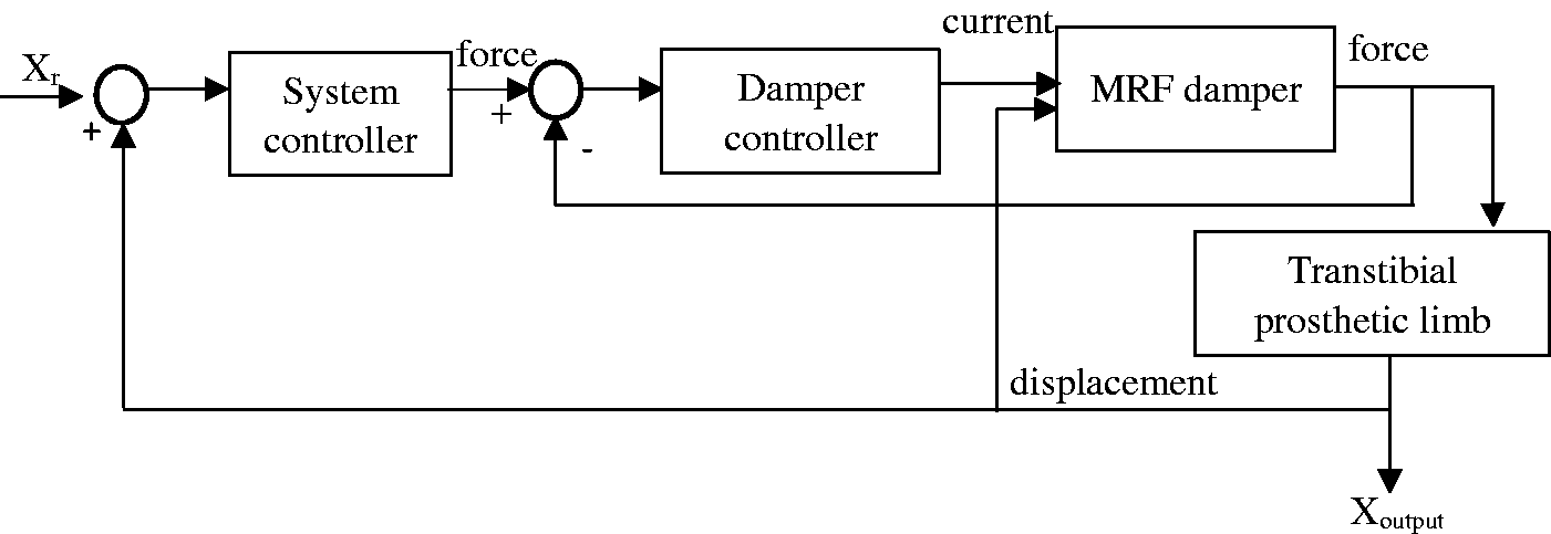
Block diagram of MRF damper in transtibial prosthetic limb.
PID controller was first used to run the system and its control system block diagram is pictured in Figure 11. Here, the values of Kp, Ki and Kd were set to 5, 15 and 2, respectively. The input applied was in the form of a pulse. The PID controller will determine the amount of force needed to reduce the effect of the force experienced during an impact. The required damping force from the system will be passed to the MRF damper in transtibial prosthetic limb plant, which will then decide the amount of current to be used for the required damping force. In this work, the data obtained through the experiment were added in a look-up table. The response of the system is shown in Figure 12, along with the plots of damping force generated, shown in Figure 13.
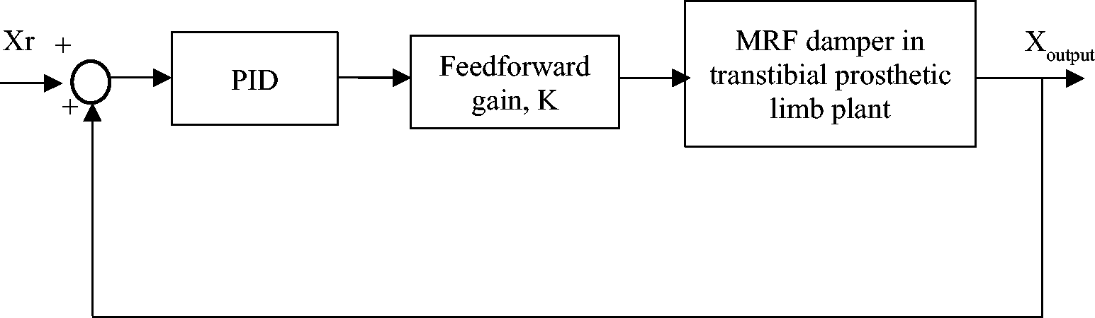
Control system block diagram.
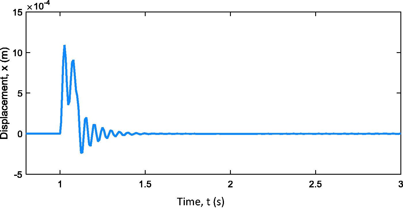
Response of the system using PID controller.
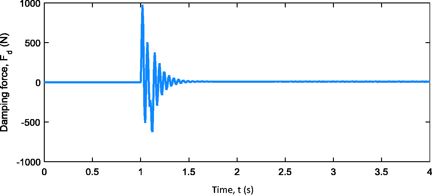
Damping force from MRF damper.
In the case of PID controller, the input is at a single frequency. To exhibit the performance of the controller at varying frequency, chirp signal was used as the input in Simulink. From Figure 14, it is shown that PID controller is not capable of controlling the vibration at varying frequency. Thus, fuzzy logic was integrated to the PID controller, to further enhance the performance of the controller. The F-PID works by adjusting the value of kp, ki and kd required by the system.
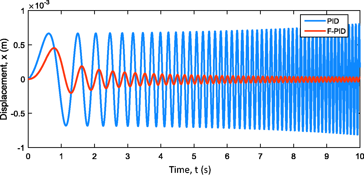
Comparison of the response of the system using PID and F-PID controllers.
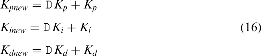
Initially, the equation describing the PID controller was expressed as

It was then rewritten as

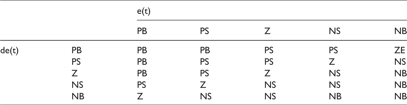
The input signals to the system were split into five fuzzy levels namely PB (positive big), PS (positive small), Z (zero), NS (negative small) and NB (negative big). The shape of the membership functions used is in the form of triangular, which is widely practised. The rules governing the decision of the controller are listed in Table 3.
F-PID controller decision rules.
The controlled outputs of the system, using PID and F-PID controllers are plotted in Figure 14. It is clear that the implementation of F-PID controller manages to suppress the vibration and thus protecting the whole structure of the prosthetic limb as well as the amputee.
Conclusion
The use of semi-active damper in prosthetic limb seems to be advantageous as it is able to offer a wide dynamic range of damping force. This research utilizes magnetorheological fluid (MRF) damper that is able to provide variable damping, based on the amount of magnetic field induced in the fluid. The implementation of MRF damper in prosthetic limb is aimed at reducing injuries and gives comfort to the amputees, due to its adaptability to the ground and impact. To suppress the vibration effectively, an adaptive controller is used in this work. Comparisons are made for the system with PID and F-PID controllers. The performance of the transtibial prosthetic limb with MRF damper using both controllers is also shown. The results show that implementing F-PID controller in the system gives better performance to reduce the vibration.
Footnotes
Declaration of conflicting interests
The author(s) declared no potential conflicts of interest with respect to the research, authorship, and/or publication of this article.
Funding
The author(s) disclosed receipt of the following financial support for the research, authorship, and/or publication of this article: This work was supported by Exploratory Research Grant Scheme (ERGS13–020-0053) from the Ministry of Higher Education Malaysia.