
Abstract
Dynamic simulation based on modelling has a significant role during a vehicle development process. It is especially important in the first design stages, when relevant parameters are to be defined. Power train mounting system is exposed to thermal loads which can lead to damage and degradation of its characteristics. Therefore, this paper aims to analyse conversion of mechanical work into heat energy in power train mounting system using a method of dynamic simulation. Considering the presence of classic–mechanical and hydraulic power train mounting systems in modern trucks, analysis of power train mounting thermal loads of FAP 1213 vehicle was conducted. Thermal loads of vehicle power train mounts were calculated by dynamic simulation, while their cooling process was not analysed.
Introduction
It is well known that noise and vibration transfer from the vehicle power train unit to the vehicle carriage system. To alleviate this impact to a satisfying measure, the power train unit is connected to the carriage system through elastic mounts. 1 At the same time, the carriage system also absorbs vibrational excitation, which is transferred from the road to the vehicle power train through the carriage system. Trucks are often exposed to severe vibration transferred from rough road. 2 Due to kinetic energy of the power train unit, which is a consequence of vibrations, mechanical work is converted to thermal energy in its mounts. 3
In practice, during the stage of vehicle development, a power train mounting system is selected in order to meet the condition of damping the vehicle vibrations. However, it should be noted that mechanical loads (forces and moments) as well as thermal loads act on the power train unit’s mounts. Thermal loads of the mounts are caused by transfer of the thermal energy of the engine (by radiation, conduction and convection in rubber–metal–hydraulic mounts) and by transformation of mechanical work into heat energy. Considering that the aim of this paper is to show in which way the design (type) of the mount influences the transformation of kinetic energy (mechanical work) into heat energy due to vibration, the influence of the heat conducted from the engine to the mounts of the power train unit was neglected, because of the complexity of the problem.
In order to avoid the negative impact on power train mounting system function, thermal loads should be taken into consideration. 3 The goal is to convert, as much as possible, mechanical work received from the ground and the power train into thermal energy, which will be transferred to the environment and thus provide the cooling of power train mounting system. Wrong selection of the mount characteristics from the aspect of thermal loads can cause rapid degradation of its properties during service life. Excessive amount of thermal energy, eventually kept ‘inside’ the mounts, would cause rapid deterioration of sealing elements and loss of function of the damping element.
Tests have shown that mechanical work is partly converted into the heat transferred to the mounts, and the remaining amount of heat is transferred to the environment, thus cooling the power train mounting system. Mathematically, this can be displayed by the formula3–8

The work of the force in the mount is important because it enables the analysis of its transformation into thermal energy. The work of force in the mount is experimentally measurable, but it is hard to measure the amount of heat released from the mount. This phenomenon is complex and difficult to measure because it is known that a part of the energy is consumed to heat the mount’s elements, working fluid (in case it exists), etc. In addition, the nature of heat transfer from the mount to the environment is very complex. Heat transfer is carried out by convection (as dominant) but also by conduction and radiation. 3
From the point of maximal cooling, proper selection of mounts requires a comprehensive analysis of the transformation of mechanical energy into heat. Method of transformation of mechanical energy into heat is largely determined by the mount design. It is not possible to directly influence the conduction of heat and radiation from the mount. It is necessary to increase the influence of the heat transfer by convection from the mounts to the surrounding environment, as dominant appearance. The idea is to utilize convection flow of air around the mount with the least complexity of the structure. In practice, this solution is rarely used but may be applied. Making some kind of air deflectors on the elements of the body should increase the effect of convective heat transfer to the environment.
Cooling of the power train unit’s mounts is a very complex process that can be difficult to encompass by the model because it requires complex experimental research in identical ambient conditions (conditioning). In the absence of the other authors’ results, the paper does not deal with analysis of this influence on the results obtained. Thus, the objective of this study was not to analyse the cooling of the mount, but only the thermal loads to which it is exposed. The amount of heat produced by the engine operation and transferred to the power train mounts was also not observed in the paper. The research was focused on the amount of heat generated by mechanical work of the elastic and damping forces due to engine vibrations. Therefore, the heat obtained by converting mechanical work into thermal energy per time unit was analysed. Mechanical work in power train mounting system was calculated by the use of mechanical power train model, which will be discussed below.
It is well known that vibrations of the power train are investigated in detail.9–11 However, there are very rare cases of research of the power train mounts’ thermal loads. Classic power train mounts consist of metal–rubber elements, with damping coming from rubber hysteresis and additional hydraulic damping from the oil streaming through them. Considering the presence of classic–mechanical and hydraulic power train mounting systems in modern trucks, analysis of power train mounting thermal loads of a FAP 1213 vehicle 12 was conducted.
Power train unit model
Various mechanical models of power train unit and vehicle may be found in literature, depending on the task that is resolved. From the literature,13–18 it is known that vibrations of a cab and a cargo crate may be neglected during analysis of conveying the dynamical loads from the power train unit to the truck’s chassis frame. More precisely, the analysis included only the vibrations of the power train unit and corresponding excitations from the vehicle’s chassis frame.
General rule for modelling of mechanical systems and, in this case, for modelling of power train unit vibrations is to select the model structure that includes a minimal number of parameters that enable the analysis of the observed quantity. This indicates the need to use the simplest mathematical models, because, due to lack of precise data on the inertial parameters of the power train unit and the characteristics of the mounts, models that are more complex may lead to occurrence of major errors. 9 In this case, FAP 1213 12 truck was observed. The scheme of the power train mounting system of the selected truck with four mounts (1–4) is shown in Figure 1.
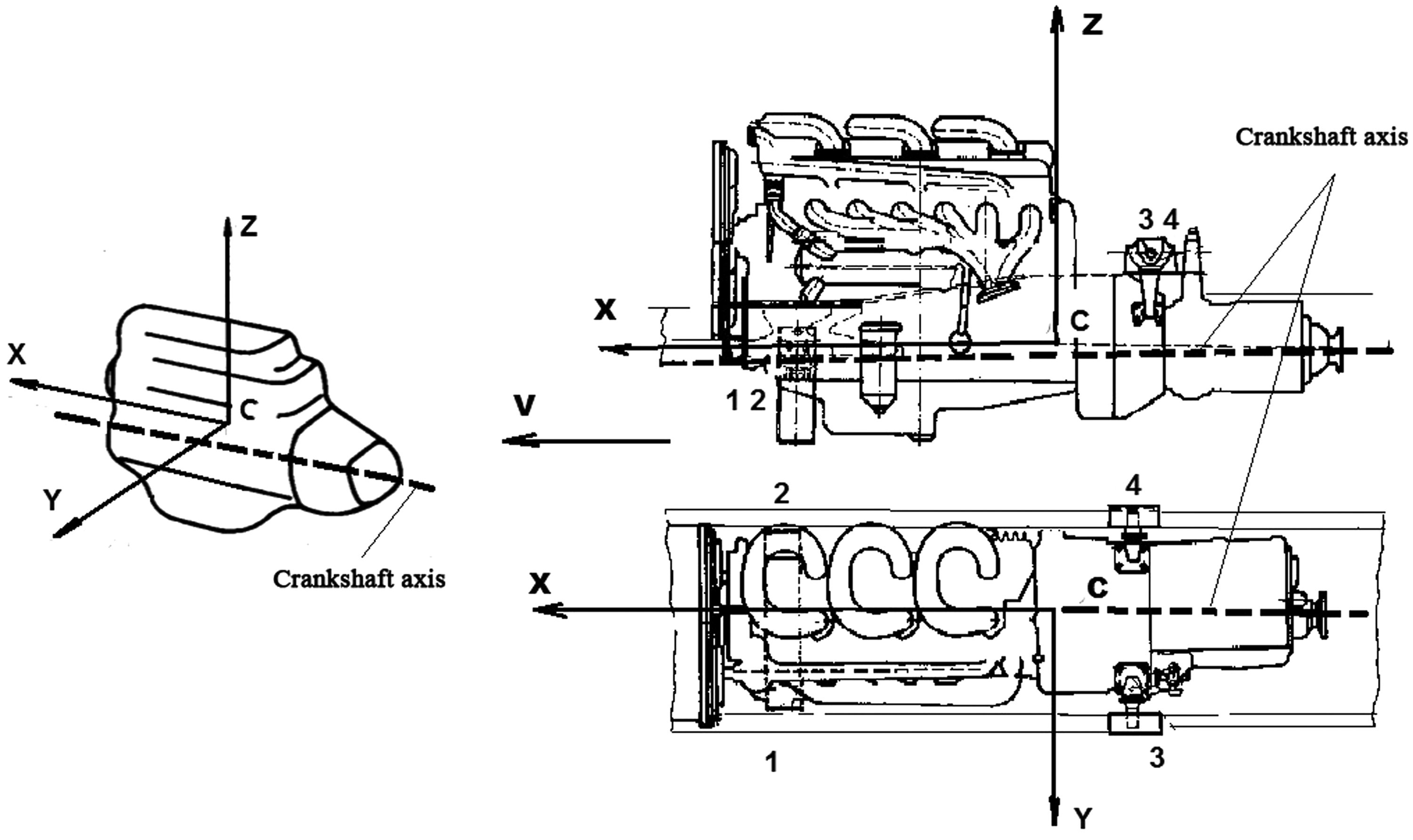
Scheme of the power train mounting system of the observed truck with crankshaft axis.
The power train unit, as rigid body in space, has six degrees of freedom of movement (three translations and three rotations).9,11,13–28 To describe its spatial movements, a rectangular Cartesian coordinate system was adopted, with the coordinate beginning at the power train unit’s centre of gravity in equilibrium position and one axis parallel to the engine’s crankshaft axis. Axes adopted in this way are called geometric gravity axes, and they coincide with the axes frequently used by the producers of the power train units. 9 The application of geometrical gravity axes implies the use of the centrifugal moments of inertia. The introduced coordinate axes, with the origin in point C, do not coincide with the principal axes of inertia. Positions of the principal axes of inertia are defined by nine angles in regard to the geometrical axes of inertia. Testing the moments of inertia using the torsional pendulum 12 has shown that these angles are less than 2.5° in the case of the observed truck’s power train unit. Thus, an approximation that the principal axes of inertia coincide with the geometrical axes of inertia for the truck power train unit may be adopted, which significantly facilitates the analysis.
Two coordinate systems were adopted to describe vibrations of the power train unit (Figure 2):
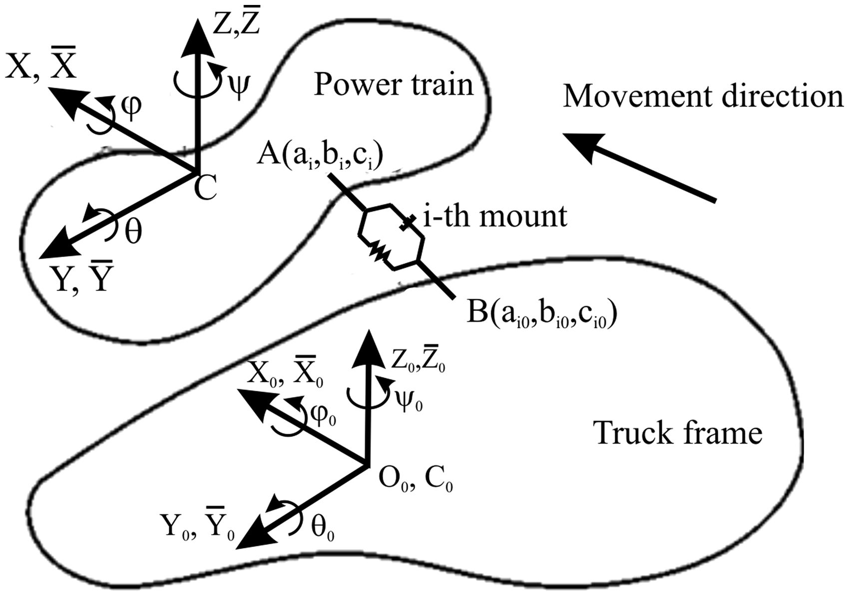
Coordinated systems introduced in order to describe the power train unit’s movement.
stationary coordinate system (
moving coordinate system (
Spatial movements of the power train unit gravity centre are defined by three coordinates, X, Y and Z, while its rotation about gravity centre (as stationary point) is described by three angles: roll angle,
Newton–Euler equations were used to describe spatial movements of the power train unit
19


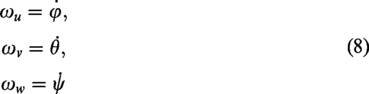
In order to simplify, an assumption is made that angular motions of the power train unit are small. Thus, the following relations may be assumed
9
There are different designs of the power train mounts: rubber–metal (classic), rubber–metal–hydraulic (hydraulic in the further text), active (with feedback), etc. 9
Since the goal of this research was to investigate the thermal loads of classic and hydraulic mounts generated by vibrations, they will be shortly described.
Figure 3(a) shows one type of design of the power train unit’s rubber–metal mount. Its elastic characteristics depend on the rubber’s shape and hardness, while the damping that originates from hysteresis of rubber is relatively small. In order to increase the amount of damping force, rubber–metal mount is supplemented by hydraulic chambers through which the oil flows (Figure 3(b)). This greatly improves the damping characteristics of these mounts. Since the goal is for both types of mounts to have the same static characteristics and partially the same hysteresis, existence of additional oil chambers in the case of hydraulic mounts results in increase of their dimensions. It should be noted that these mounts do not find broader application in practice due to complexity of their design, higher thermal loads and higher price.
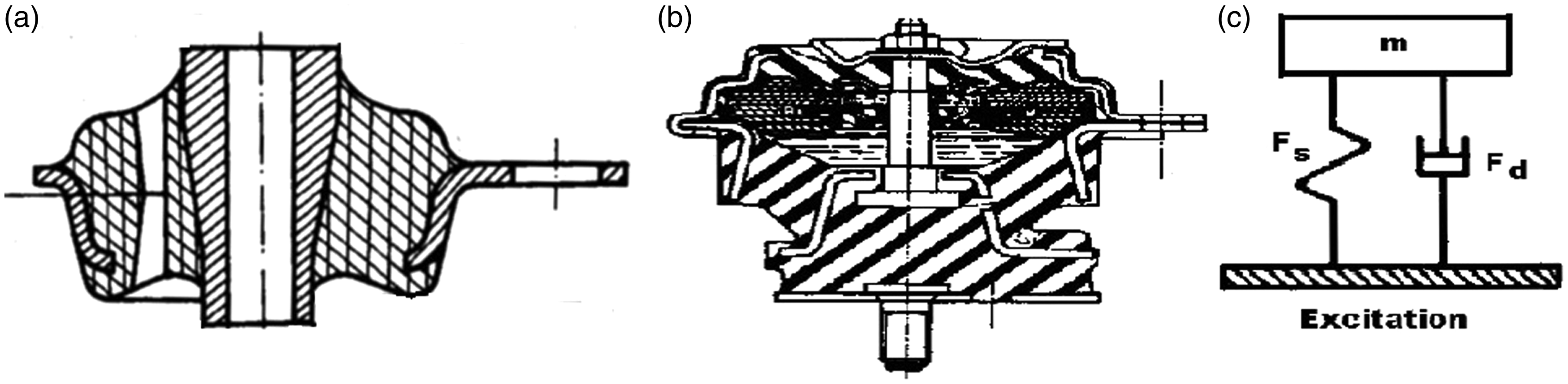
Types of engine mounts and their model: (a) rubber–metal mount, (b) rubber–metal–hydraulic mount and (c) Kelvin’s model of the engine mount.
Different models are used to model both types of mounts. The most frequently used are Kelvin’s, Maxwell’s and combined Kelvin–Maxwell models.9,13 This paper utilizes Kelvin model shown in Figure 3(c) which means that elastic and damping forces that balance mass, m, are parallel. As the design of the suspension requires consideration of the resonance (9–11 Hz in vertical direction) and 3–5 mm of horizontal movement, 9 this practically means that static rigidity of the both types of mounts must be the same. Consequently, corresponding elastic forces and forces form rubber hysteresis are almost the same and, due to the greater damping force in hydraulic mounts, their resulting force is greater. This fact is of great importance, because the power train unit has more favourable vibration parameters in the case of utilization of hydraulic mounts. However, their thermal loads must also be observed and that is the goal of this paper.
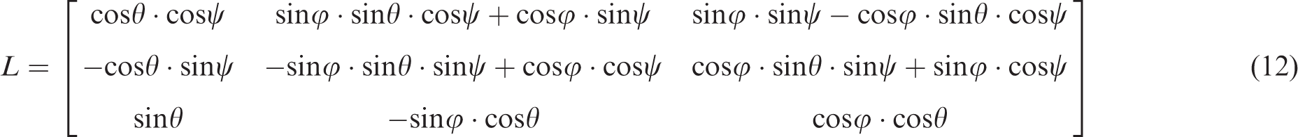
In order to calculate the forces in the mounts, it is necessary to define mounts deformations and velocity of deformations. Considering the adopted coordinate systems, movement vector,

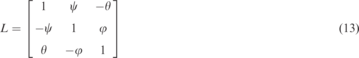
For small angles, the transformation matrix becomes
Similarly, considering the small vibrations of the truck’s chassis frame, for any point on the frame, corresponding coordinate vector

Since the dimensions of the mounts are small in comparison with the dimensions of the power train unit, the following may be written
Deformation of the ith mount,

By substituting the corresponding expressions and some arranging, the following relations are obtained


Deformation velocities of the mounts may be obtained by differentiation of equations (20) to (22)


There are many mathematical models of the power train unit’s mounts in the literature, which are, basically, more or less complicated. Some of them also include fluid flow within the mounts, which is a complex problem.9,11,13–28
Considering that the aim of this paper was to investigate the mount’s thermal loads, simpler expressions for approximation of the forces acting on the mounts were used.
The forces in elastic mounts are represented in the following form

The hydraulic mounts function as absorbers, and, in the absence of a mathematical model, which is very complicated, the same form of the damping force is adopted as in the case of the vehicle’s shock absorbers. The damping forces in the mounts are adopted in the following form

The power train unit’s vibrations also depend on engine operation imbalance–engine torque,
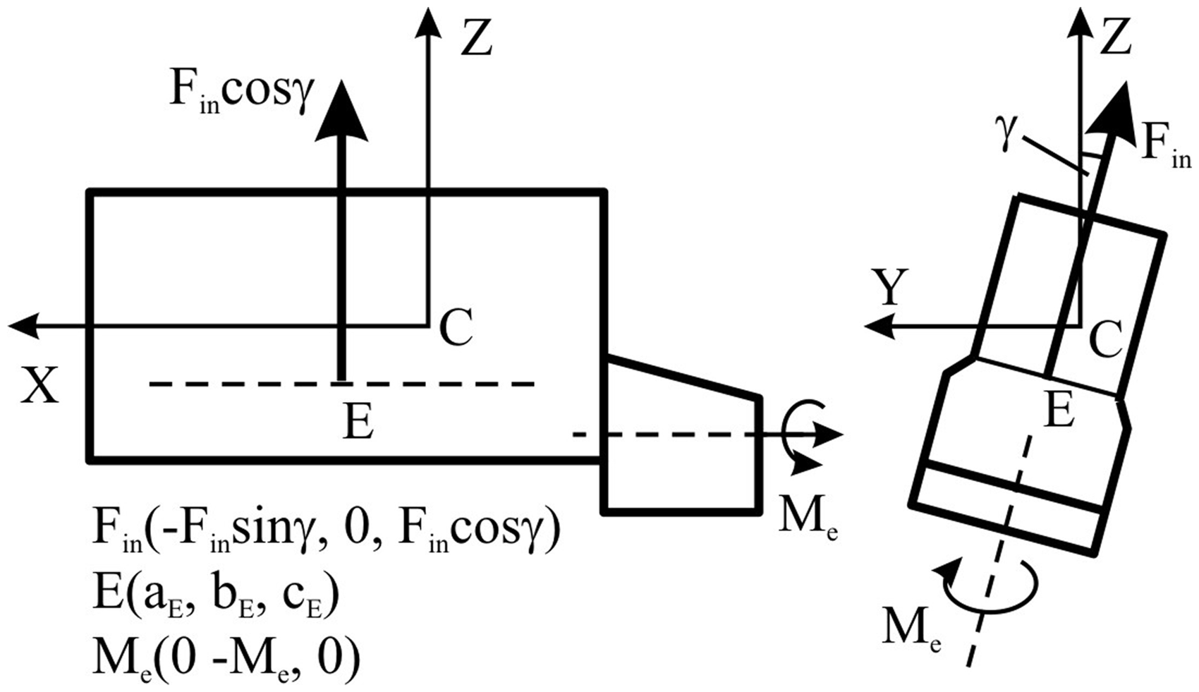
Engine’s inertial force and torque.
Designations in Figure 4 are the following:
In concrete case, a four-stroke four-cylinder line diesel engine was used with crankshaft having throws in the same plane (at
Assuming that higher order harmonics may be neglected, the resultant unbalanced inertial force of the observed engine may be expressed in the following form9,29

Using elementary knowledge of the theory of vectors and postulates of statics and considering Figures 2 and 4, moment from the inertial force,
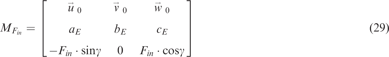
Nomenclature from equation (29) is in accord with Figure 4.
Centrifugal forces are partially balanced by applying counterweights or other procedures, which will not be described here, but readers are referred to Mahalec et al. 29
Tangential force provokes the engine torque, which, due to tangential force variations, has variable values (the engine’s flywheel partially balances this imbalance). 29
Missing the more precise data, an assumption is made that the turning down moment of the power train unit equal to drive wheels torque, M, may be described by the expression

Vibrations of the power train unit are also influenced by random vibrations of the truck’s chassis frame.9,11,13,17 Considering that the complexity of the vehicle spatial model exceeds the needs of this paper, model-based excitations of the truck’s frame were not used, but broadband excitation functions in the form of

Projections of the generalized forces contain all components of forces and moments of corresponding mounts in the direction of the observed axis (for mounts 1–4), inertial forces and engine torque (imbalanced inertial forces).
Taking into account equations (1) to (30), the following differential equations of the power train unit’s motion may be written


Thermal loads of the power train mounting system
Due to the relative motion of sprung and unsprung masses, mechanical work is being done in mounts, which is equivalent to the amount of produced heat, Q.
3
Mechanical work (the amount of heat) is defined by the expression3–8

Mechanical power,
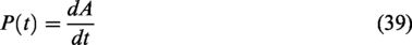
Average power,


As already noted, the analysis of heat transfer from the mount has not been carried out in the paper, because the values of
Since all four power train unit mounts had the same characteristics, the analysis of collective thermal loads was conducted.
Numerical simulation and analysis of the results
Based on equations (1) to (42), it may be seen that differential equations describing the spatial vibrations of the truck’s power train unit are non-linear. Thus, they need to be solved numerically, using the Runge–Kutta method. Integration was done in 524,288 points, with integration step of 0.0001. This has enabled reliable analysis in domain between 0.019 and 5000 Hz.30–32 It is obvious that this range is considerably larger than excitation range due to engine and complete power train unit operation. Integration of differential equations was done for the case of using classic and hydraulic mounts, using a program developed in Pascal programming language (developed by the authors).
More precise analyses regarding errors during spectra calculation 30 show that it is necessary to conduct 100 averaging for auto-spectra calculation and 138 averaging for cross-spectra calculation to achieve relative random error of 0.1, relative bias error of 0.02 and coherence between input and output quantities of 0.85. Since the used software conducted 2048 averaging, it is obvious that the achieved errors in spectra calculation were considerably smaller than upper limits for technical systems.30,31
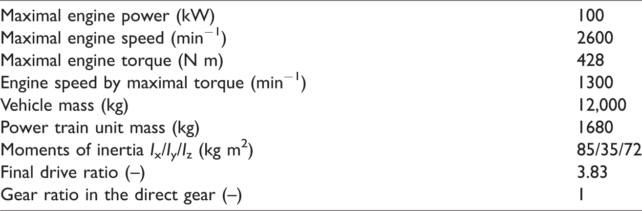
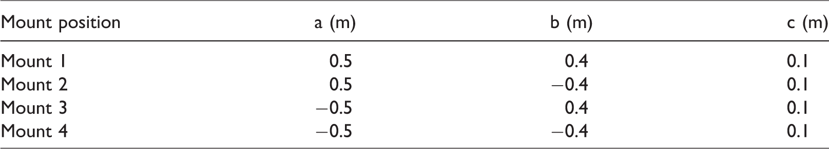
Parameters of the observed truck and its power train unit are given in Table 1 and coordinates of the connecting points (mounts) are given in Table 2.
Characteristic parameters of FAP1213 truck and its power train unit. 12
Coordinates of mount’s connecting points.
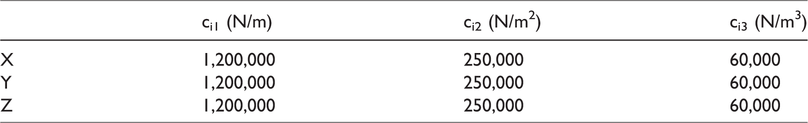
Mechanical and hydraulic mounts had the same stiffness coefficients in directions of X, Y and Z-axis, confirmed by testing in FAP 12 and shown in Table 3.
Stiffness coefficients of classic and hydraulic mounts.
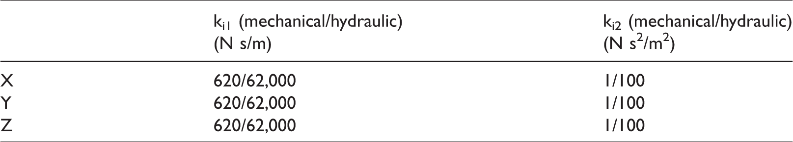
In the absence of more precise data, damping characteristics of the mounts were approximately defined based on stiffness coefficients of the mounts and mass that they carry 12 and given in Table 4.
Assumed damping characteristics of the mounts.
It was assumed in the paper that the chassis frame had six excitations in time domain, equation (31). For illustration, vibration excitations of the power train unit originating from the frame excitation are shown in Figure 5 (B, C, D are longitudinal, lateral and vertical vibration excitations, respectively, while E, F, G are roll, pitch and yaw of the vehicle frame, respectively). It is obvious that excitations are very changeable in time, so large thermal loads of the power train unit are to be expected.
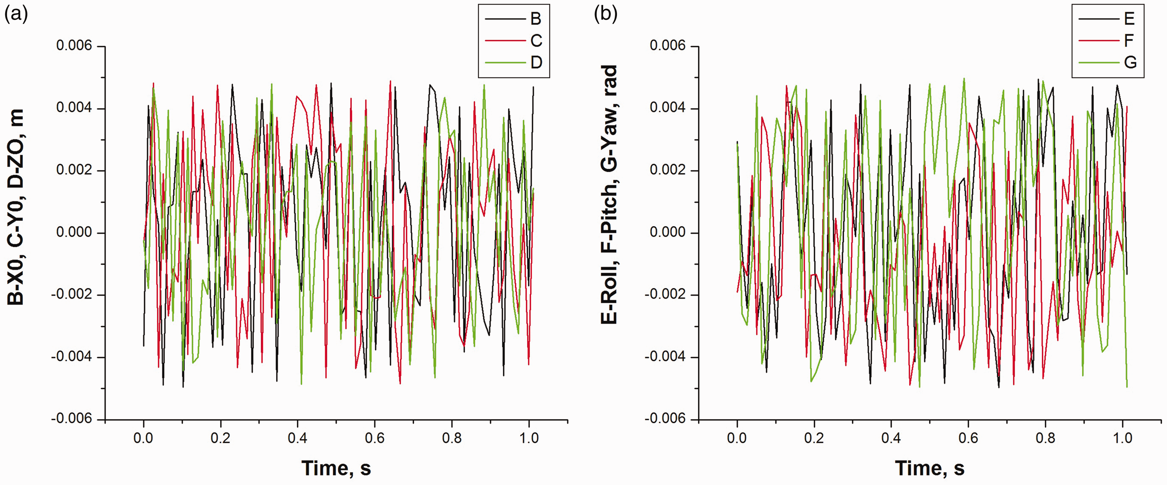
Illustration of the frame excitation: (a) linear excitations and (b) angular excitations.
By using equation (38), quantity of heat (mechanical work) was calculated and, based on that, heat flux was calculated using equation (39).
Since the aim of the research was to establish which excitation component (including excitation forces from engine inertial force and turning down moment) had the greatest influence on thermal loads of the power train unit mounts, this problem is elucidated in more detail.
Multiple input/single output dynamic system can be presented as shown in Figure 6. If there is a coupling between inputs, the system must be decoupled.30,31 In this case, the thermal loads of the system depend on eight inputs (three translations, three rotations, two engine excitations). Thus, the theory enabling the analysis of influence of each excitation on thermal loads of the power train unit mounts will be briefly presented. Figure 6 shows the block diagram of the system and Figure 7 shows a block diagram of the decoupled system.30,31
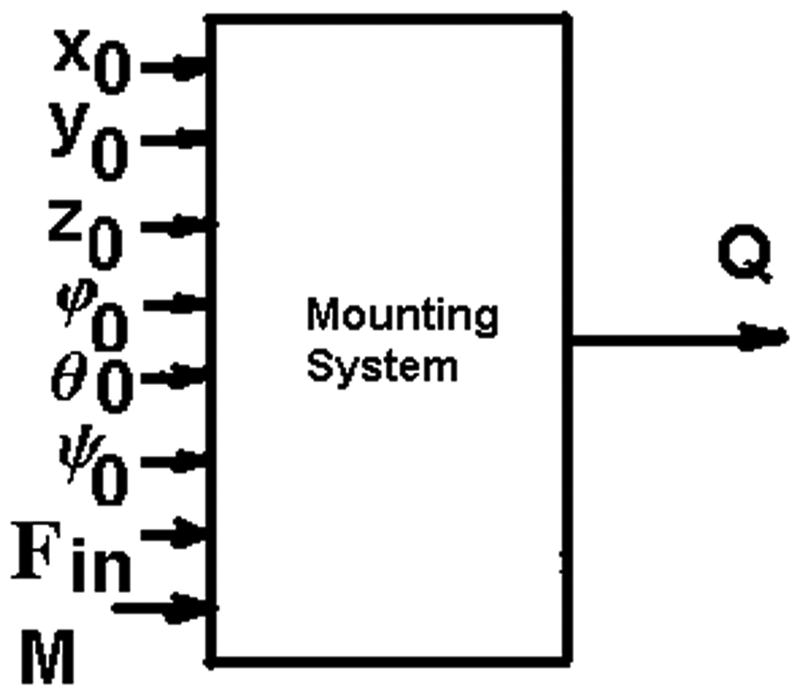
Power train mounting system block diagram.
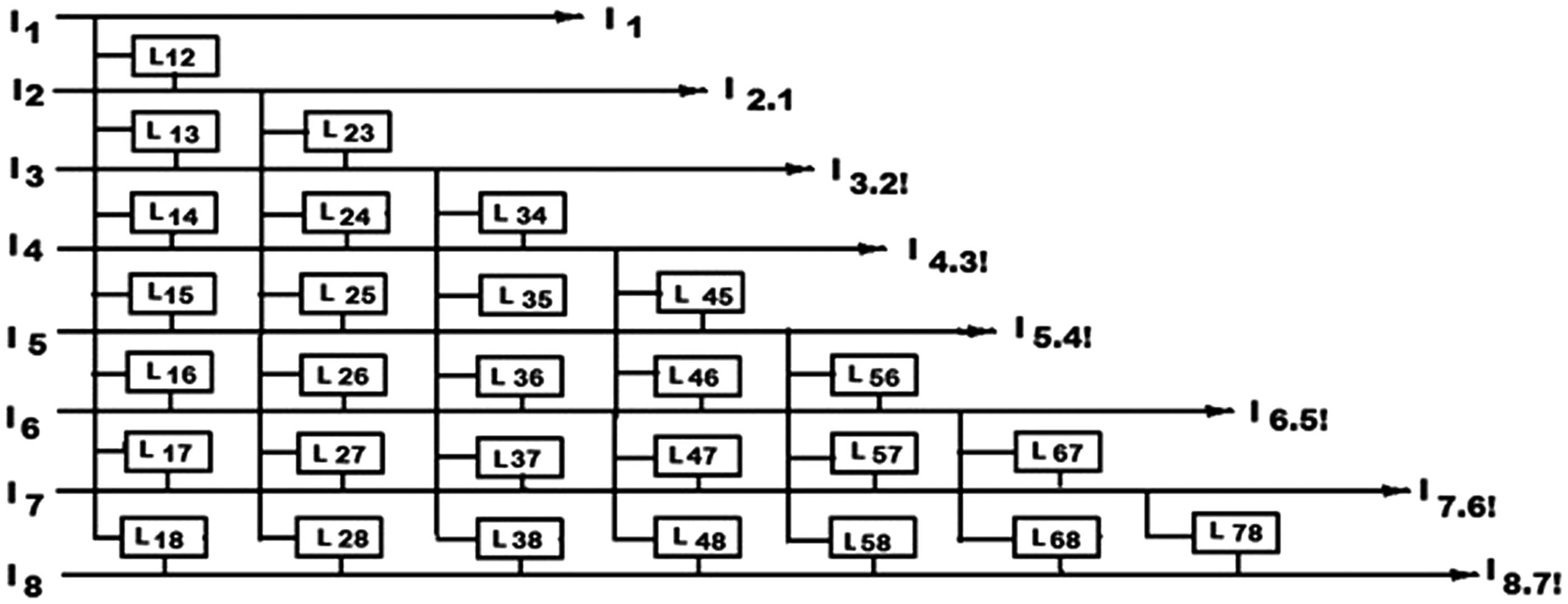
The decoupling scheme.
Designations in Figures 6 and 7 are as follows:
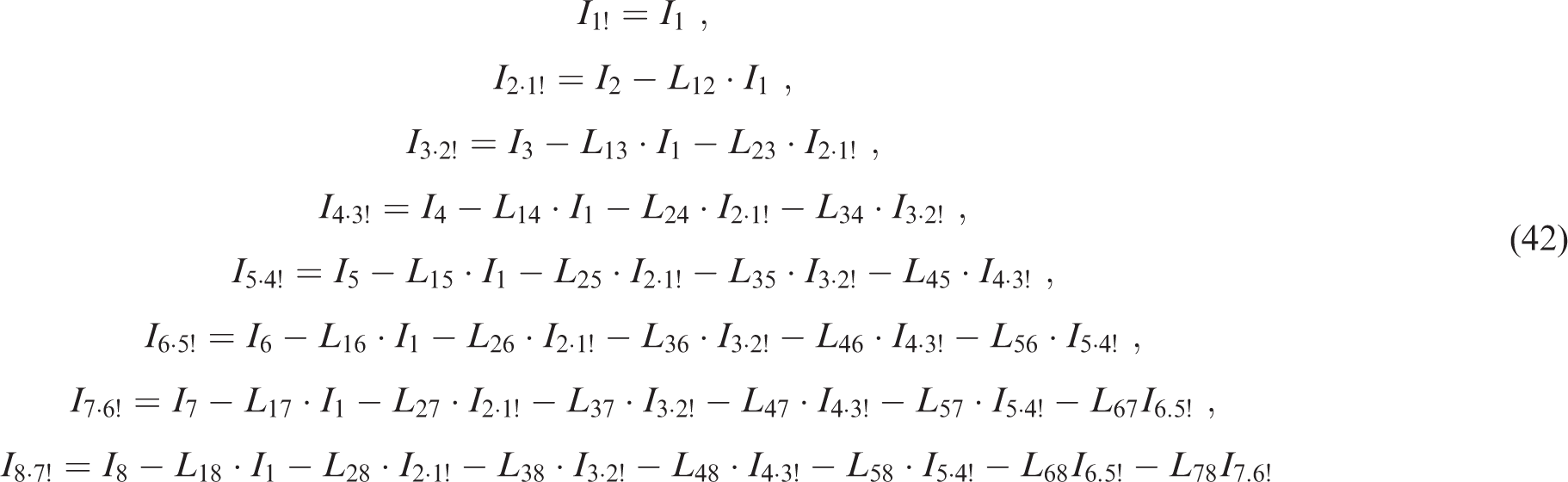
Taking into account the theory from Bendat and Piersol30,31 and Figure 7, the following expressions may be written
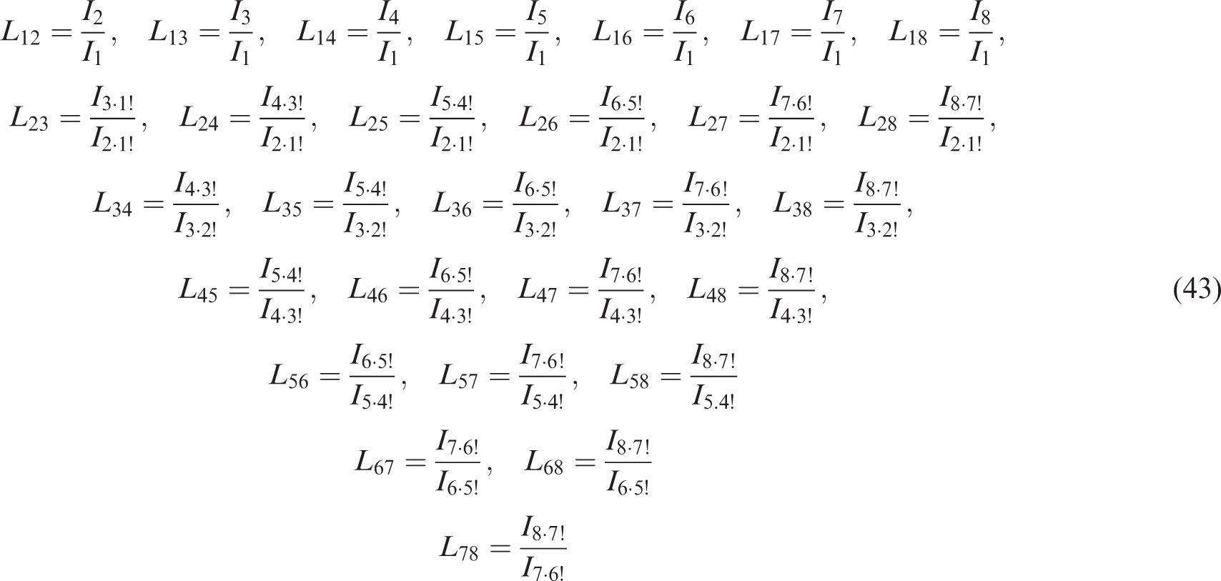
Frequency response functions between input vibration excitations may be presented in the following way (designations in accord with Bendat and Piersol30,31)
Partial coherence functions that reflect the coupling between input and output signals can be calculated based on previous expressions30,31
Cumulative thermal loads (for all forces and moments components and for all four mounts) were calculated using equations (2) to (39). The results are shown in Figures 8 and 9, whereby heat quantity values are given in logarithmic scale in Figure 8.
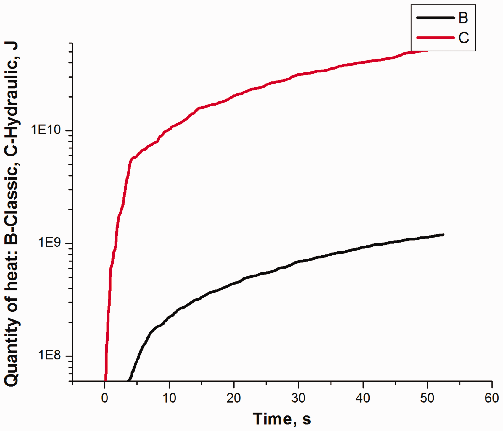
Quantity of heat (mechanical work) depending on the type of the mount: B –classic, C – hydraulic.
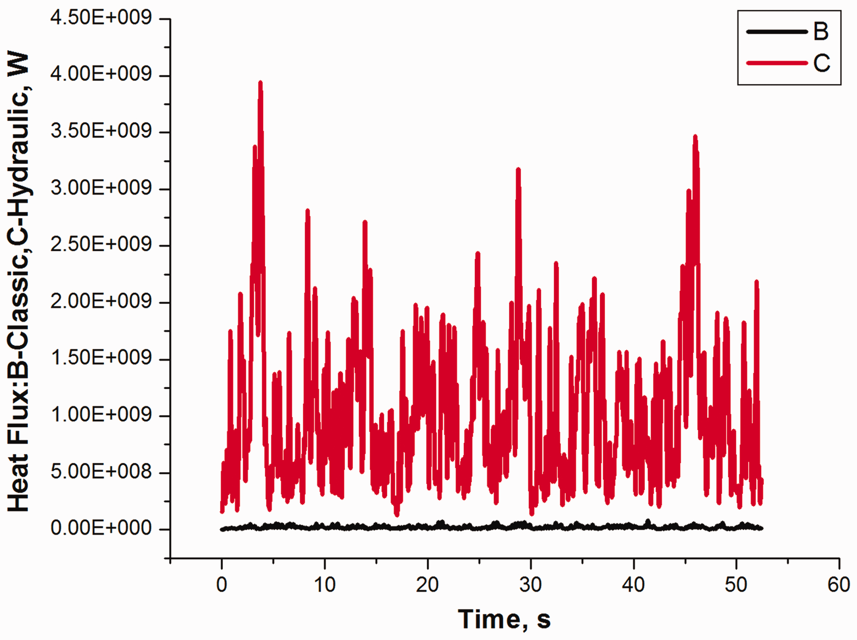
Thermal flux depending on the type of the mount: B – classic, C – hydraulic.
By analysis of a diagram in Figure 8, it can be noticed that mechanical mounts suffer around 45 times less thermal loads than hydraulic mounts (classic mounts around
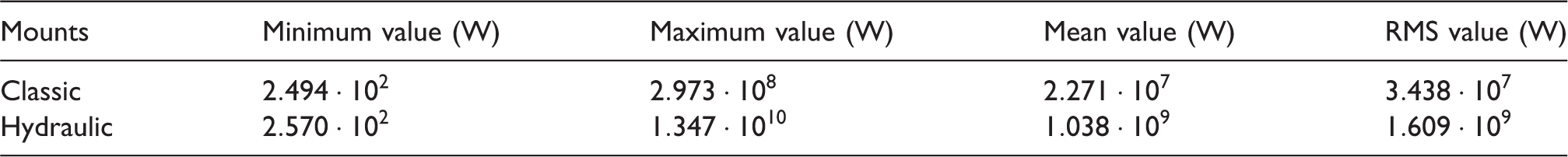
Figure 8 shows that quantity of heat increases over time. In case there is no cooling, the mounts would sustain degradation of shapes and characteristics. Figure 9 shows thermal flux dependence on time. It is obvious that it changes randomly over time, so in order to conduct the analysis, it was necessary to calculate some characteristic statistical values (minimum, maximum and RMS values), given in Table 5.
Statistical data on thermal flux.
RMS: root mean square.
Analysis of data from Table 5 shows that thermal flux in hydraulic mounts is considerably larger than in classic power train mounts. It points to possible greater degradation of hydraulic mounts characteristics compared to classic mounts. High values of hydraulic mount’s thermal flux quantity are the product of rigorous excitations from the chassis frame that are used for simulation. These excitations are considerably smaller in practice.
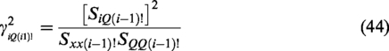
For detailed analysis, partial coherence functions were calculated according to equation (44). Figure 10 shows calculated values of partial coherence for classic mounts.
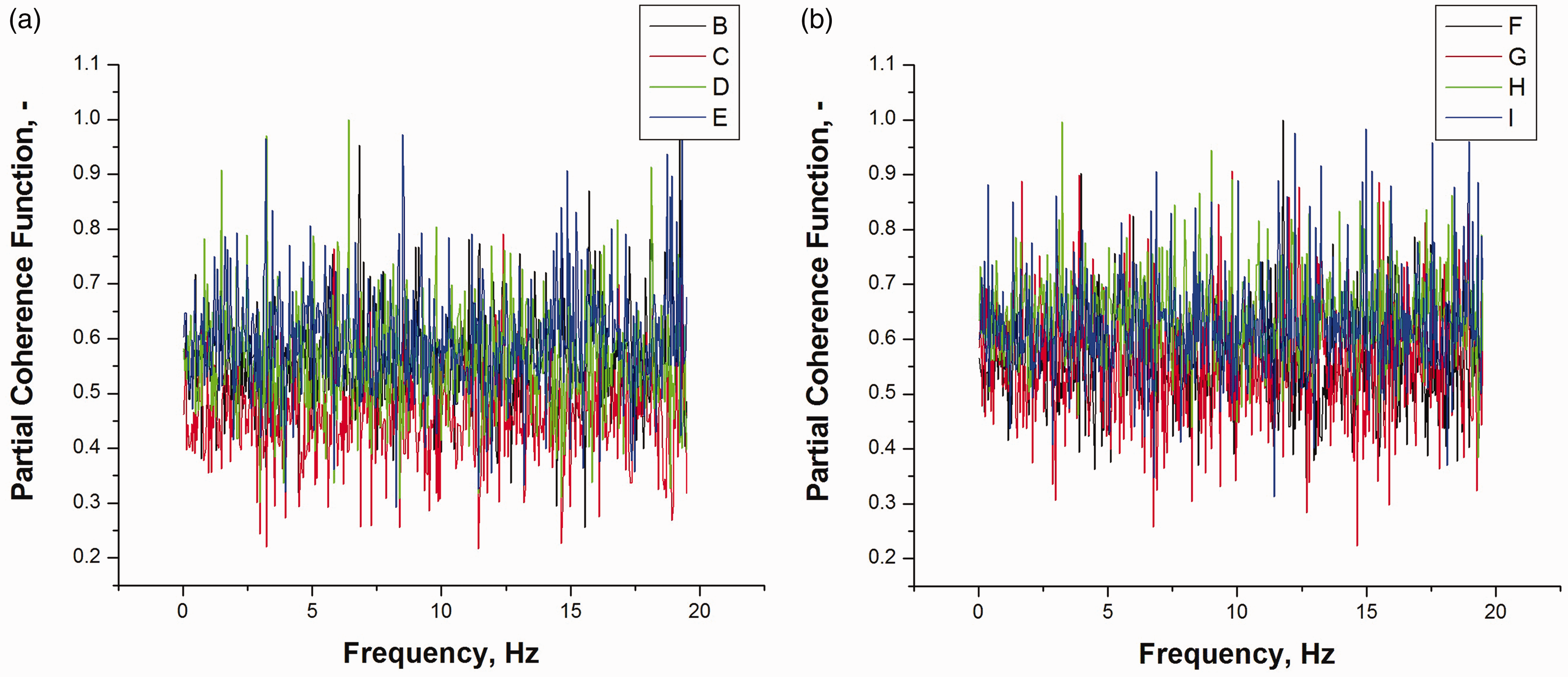
Partial coherence functions for classic mounts.
Designations of individual partial coherence functions in Figure 10 are as follows:
Figure 10(a)
B – longitudinal excitations from the frame, C – lateral excitations from the frame (influence of longitudinal excitations excluded), D – vertical excitations from the frame (longitudinal and lateral excitations excluded), E – the frame’s roll (influence of longitudinal, lateral and vertical excitations from the frame excluded),
Figure 10(b)
F – pitch (influence of longitudinal, lateral, vertical and roll excitations from the frame excluded), G – yaw (influence of longitudinal, lateral, vertical, roll and pitch excitations from the frame excluded), H – engine inertial force (influence of excitations from the frame excluded) and I – power train torque (influence of excitations from the frame and engine resulting inertial force excluded).
Analysis of data for hydraulic and classic mounts shows that partial coherence functions depend on frequency and the type of excitation. For more detailed analysis of partial coherence functions, minimal, maximal and RMS values of partial coherence functions were calculated and presented in Tables 6 and 7, using the same notation as in Figure 10.
Minimal (min), maximal (max) and effective (RMS) values of partial coherence functions for mechanical (classic) mounts.
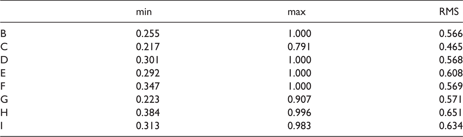
RMS: root mean square.
Minimal (min), maximal (max) and effective (RMS) values of partial coherence functions for hydraulic mounts.
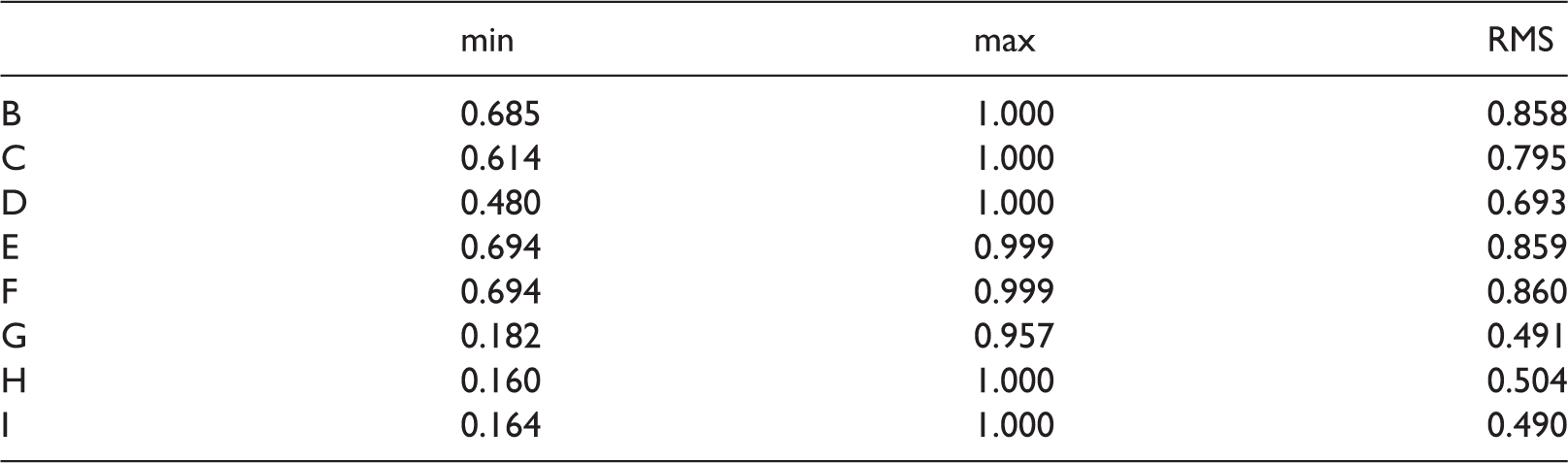
RMS: root mean square.
Calculated values of partial coherence functions from 0.160 to 1 in Tables 6 and 7 indicate that there is a coupling between input values and thermal flux.30,31 RMS values of partial coherence functions for hydraulic mounts are somewhat larger in case when excitations from the frame are input quantities, compared to values for mechanical mounts. The opposite stands for excitations from inertial forces and moments and that speaks about the influence of characteristics of the used mounts on dynamic vibrations of the power train unit.
In the case of classic mounts, engine inertial force has the greatest influence on thermal loads, while lateral excitation from the frame has the smallest influence. For hydraulic mounts, pitch vibrations of power train unit have the greatest influence, while power train torque has the smallest influence.
There are obvious differences between the classic and the hydraulic mounts regarding the influence of the observed excitations. This can be explained by the fact that the applied types of mounts lead to different vibration characteristics (amplitude and frequency) of the power train unit.
Thermal loads originating from the transformation of mechanical work into heat energy lead to degradation of characteristics of mounts and therefore to changes of power train unit’s vibration parameters. However, this effect was not analysed in the paper since conducted research did not include laboratory tests of degradation of characteristics of the power train unit mounts.
Research presented in this paper had a goal to establish the ratio of thermal loads of classic and hydraulic mounts by using the model. Thus, the obtained data may be adopted as approximate, which is necessary in the conceptual design phase of the truck.
Conclusions
Based on the conducted research, the following conclusions may be drawn:
adopted model of the power train unit may be used for simulation of thermal loads of the truck’s power train unit’s mounts, considering the goal that for both classic and hydraulic mounts resonant frequencies should be the same (equal static deflections) and the fact that hysteresis originating from rubber is approximately the same in both cases, hydraulic mounts are exposed to larger thermal loads (larger mechanical work) due to their greater damping force, considering higher thermal loads, more complex structure and higher prices, less frequent application of hydraulic mounts for power train units of the trucks is understandable, engine inertial force has the greatest influence on thermal loads, while lateral excitation from the frame has the smallest influence in the case of classic mounts, for hydraulic mounts, pitch vibrations have the greatest influence, while power train torque has the smallest influence on thermal loads.
Footnotes
Declaration of conflicting interests
The author(s) declared no potential conflicts of interest with respect to the research, authorship, and/or publication of this article.
Funding
The author(s) disclosed receipt of the following financial support for the research, authorship, and/or publication of this article: This work was supported by the Ministry of Education, Science and Technology of the Republic of Serbia (grant number TR35041).