
Abstract
This paper is concerned with an experimental study of improved slotted stand-off layer rail dampers in reducing railway vibration and noise. To achieve the goal, based on the idea of molecular design, polyurethane/vinyl ester resin interpenetrating polymer network damping materials with high damping properties was developed in the laboratory for the material of the damping layer. The effects of vinyl ester resin and organic small molecule hybridization on the damping properties of the polyurethane/vinyl ester resin interpenetrating polymer network material were investigated. The structural style of the damper was improved for ease of installation and removal in situ. Then, these improvements of damping material and structural style were used to make optimized slotted stand-off layer dampers, which were applied in a test section. The measurements indicate that the structural style improvement could improve the application convenience while also maintaining the noise reduction effect. The improved rail dampers could greatly increase the track decay rate at frequencies above 100 Hz and reduce noise levels by up to 6 dB at the speed of 60 km/h.
Keywords
Introduction
In today’s world, with increasing high-speed railway lines and urban rail transit, the noise caused by rail transit is a matter of increasing environmental concern to areas surrounding railway tracks. Several studies have attempted to resolve this issue and have shown that the total exterior noise generated by a passing train consists of several individual noise generating mechanisms, each with its own characteristics of source location, strength, frequency content, direction, and speed dependence. 1 However, in general, these noise sources can be broadly categorized into three major types. The first type is traction and auxiliary noise, whose sources include traction motors, cooling fans, gears, and auxiliary equipment. The next type is rolling noise, which results from wheel/rail interactions and is affected by wheel roughness, rail roughness, and the decay rates of energy in the rail. The third and final type is aerodynamic noise, which results from air flowing over the train structure. The significance of these different categories is that, for a given train, there are three distinct speed ranges in which only one sound source dominates the total noise level. 2 It has been demonstrated that the rolling noise often dominates the lateral railway noise at speeds of 40 to 270 km/h. 3
Given that the running speeds of most trains are almost always within the driving velocity range (between 40 and 270 km/h), it is very important to control the rolling noise. The vibration responses of the wheel, rail and sleeper contribute to the overall spectrum of rolling noise. Among them, the rail is a dominant source in the frequency range of 450–2000 Hz, and therefore it is one of the most critical components of railway noise emission. 4 Extensive work has focused on solutions for the reduction of rolling noise. Presently, in the field of railway noise treatment, the lineside noise barrier is one of the most widely used methods. However, there are many obvious disadvantages of this technology such as high costs (including costs for maintenance and replacement), limited effectiveness with high buildings and a negative influence on the land and cityscape. Furthermore, the central issue with the noise barriers is that they merely create local regions of noise reduction, and do not prevent the noise at its source.
Rather than erecting noise barriers in the propagation path, reducing rail noise at the source can be a more attractive solution. 5 Other attempts at reducing rolling noise have centred on ensuring the smoothness of wheel/rail interaction surface by using wheel profiling, removing corrugation, eliminating rail joints, and replacing cast iron block brakes with disc brakes to guarantee trains with smooth wheels running on smooth rails.
It is generally known that an effective vibration suppression method is to put the damping structure on the vibrating structure.6–8 Increasing rail damping is another promising means to reduce the component of the railway rolling noise radiated by the rail. A solution involves increasing the level of damping of the components through passive surface damping treatment. As a general rule, the damping factor of the rail is very small and works against the attenuation of the vibration, especially at those pinned-pinned frequencies. 9 Thus, an increase in rail damping could increase the attenuation of vibration with distance along the rail and thereby may reduce the noise radiated. At present, the literature reports many different ways of increasing the rail damping. The most important methods fall into two broad categories. Although there is no difference in their damping mechanism, the working frequency range of the two categories differs greatly. The first category includes the use of the double tuned rail damper, 10 the tuned mass damper 11 and the rail vibration absorber, 12 both as treatments applied to the rail web and rail foot and as tuned dampers. These are chiefly designed to affect only some specific frequencies. The second category is the use of free layer dampers and constrained layer dampers. This category can be effective in the entire vibration frequency range, depending on the viscoelastic properties of the damping material, and hence has an advantage over tuned dampers. 5
Wide application in the civilian industry and the munitions industry in recent years has proved that the stand-off layer damping treatment, proposed by Whittier in 1959, is the most effective method to enhance the damping characteristics of classical constrained layer damping treatments, by increasing the distance between the viscoelastic damping layer and the neutral axis of the base layer. 13 Based on this, the author proposes a novel slotted stand-off layer damper according to the rail configuration, has developed a compound track model with this treatment to investigate its effectiveness, and measured its noise reduction effect with a full scale sample in the laboratory.
Considering that the damping material has a rather narrow useful damping temperature and frequency range and the damper structure is relatively difficult to install and remove in the first part of research, the research presented in this paper focuses on the experimental study of improved slotted stand-off layer rail dampers in reducing railway vibration and noise. Two important aspects are considered by an exploratory evaluation of the damping properties of polyurethane/vinyl ester resin interpenetrating polymer network (PU/VER IPN) and an evaluation of the vibration and noise reduction of semi-slotted stand-off layer dampers using field tests. The class of absorbers considered here is based on the stand-off layer damping treatment technology. The research consists of the following stages: first, obtaining the optimal damping material, laboratory PU/VER IPN material specimens with various acrylic esters in VER’s comonomer system, component ratios of PU and VER in the IPN system and contents of organic hybrid molecules are prepared and tested to characterise their damping performance. Next, laboratory damper specimens with different structural forms but the same optimal PU/VER IPN damping material are made and tested to characterise their applicability and vibration attenuation ability. Finally, the optimal material and structure combination is used to manufacture rail dampers, which are applied in a test section. The track decay rates and railway wayside noise are measured in the test section and compared with the data obtained from the standard track without dampers and the track with dampers as in the first part of research at the same measuring site.
Previous explorations and conclusions
The configuration of the slotted stand-off layer damper is shown in Figures 1 and 2. In Figure 1, the rail is Chinese 60 kg/m rail, hs1 is the zone thickness of the slotted stand-off layer without slots, hs2 is the slot thickness of the slotted stand-off layer, ts1 is the slot width, ts2 is the zone width of the slotted stand-off layer without slots, hc is the thickness of the constraining layer, tc1∼tc3 are the three important structural dimensions of the constraining layer and α is the slope of the constraining layer. The values of these parameters are shown in Table 1. In order to facilitate the installation of the damper, the damper is divided into two symmetrical parts. The rail surface is plastered with glue first and then the two symmetrical parts are attached to the rail simultaneously.
Parameter definitions of the slotted stand-off layer damper. (a) Cross-section of the rail with slotted stand-off layer damper. (b) Detailed characteristics of the slotted stand-off layer.
Schematic plot of a rail with a slotted stand-off layer damper. (a) Real damper attached to the rail. (b) Detail of the slotted stand-off layer.
Configuration of the damper.

The slotted stand-off layer was made from Dyad606. Its density is 1200 kg/m3 and its Young’s elasticity modulus is 500 MPa. The material used for the constraining layer is steel-3Cr13Mo, with an elastic modulus of E = 206GPa. VER-IPN was chosen as the material for the damping layer and its loss-factor and elastic modulus in the temperature and frequency ranges of interest are depicted in Figure 3. E and β denote the elastic modulus and loss factor, respectively.
Diagram of damping properties of VER-IPN.
The loss factor and stiffness of the viscoelastic material are very important for the performance of the system. Unfortunately, both these properties are sensitive to changes in temperature and frequency. 14 As the rail temperature varies considerably in the course of a year, and the rail vibration covers a broad frequency range, the performance of the slotted stand-off layer damper is affected. Therefore, to improve its performance, the statistical distributions of rail temperatures and rail vibration frequencies were investigated. They were used to develop a novel damping material and an appropriate optimization procedure, which accounts for temperature and frequency variations to substitute the VER-IPN damping material in the previous work. Its material properties will be described below.
PU/VER IPN damping material was shown to have the favorable properties of epoxy resins, besides an excellent low temperature performance and a broad effective damping frequency range. 15 As a result, many experimental studies were conducted in recent years to develop high damping PU/VER IPN materials for specific uses. In general, the effective damping temperature range, frequency range, and amplitudes of PU/VER IPN damping materials are related to factors including the damping property of the two polymers (PU and VER), the degree of cross-linking, compatibility, and filler. 16 Compatibility and the degree of cross-linking are largely dependent on the types and proportions of the two polymers. Hence, the types and component ratio of the two polymers are important factors in the design of high damping PU/VER IPN materials. In this paper, to prepare damping material that could meet the temperature and frequency requirements of the rail vibration characteristics, the effects of VER on PU/VER IPN material damping properties were investigated in the optimization procedure by introducing different acrylic esters into VER’s comonomer system and different component ratios of PU and VER in the IPN system. Also, another novel technology, namely organic small molecule hybridization, was also adopted to further increase the damping properties of PU/VER IPN material for the rail damper.
Another aspect to consider in this article is the applicability of the slotted stand-off layer damper attached to the rail in guaranteeing high safety, easy inspection and easy maintenance of a track. As an auxiliary structure, the application of the slotted stand-off layer dampers has some geometric limitations. First, the designed slotted stand-off layer damper has to meet the available space restrictions. The two colored areas in Figure 4 represent the entire space available for attaching the dampers. Furthermore, to fulfill the requirements of quick installation and dismantlement in situ, more attention should be paid to the structural style of the damper. It has emerged that it is not very convenient to address the dampers developed according to the field application, and the problem mainly lies in the section of the damper that was used to cover the rail foot. Hence, some measures have been applied to improve the applicability of the previous damper under the conditions of no loss to its vibration and noise reduction effect.
Geometric limitations to the slotted stand-off layer damper design.
Improvement of rail dampers
Material properties improvement
Improvement scheme
As mentioned previously, the damping layer is the main energy dissipation part of the slotted stand-off layer damper. It is made of viscoelastic damping material, which can extract mechanical energy from a vibrating system and convert it into heat by taking advantage of the viscoelastic damping capacity around the glass transition region. However, in general, the useful damping temperature and frequency range of this type of material is rather narrow. Hence, in recent years, numerous fruitful studies have been conducted on these types of materials to improve their damping properties. Among these, the IPN is a novel type of polymer alloy consisting of two or more cross-linked polymers held together by physical entanglement. Due to its properties, such as mutual entanglement, forced compatibility, synergism of the cellular networks and dual-phase continuous microstructure, this is a promising technique of preparing materials with broad glass transition region temperature ranges and fine damping performance. 17 Additionally, these materials also exhibit excellent thermal stability and mechanical properties due to the synergistic effect induced by the forced compatibility of the individual components. 18 In the first part of the research, VER-IPN was chosen as the material for the damping layer for its high loss factor values in the temperature and frequency ranges of interest, as shown in Figure 3.
The spectral characteristics of rail vibration (which usually covers the frequency range of 40 to 1500 Hz 9 ) and the varied environmental temperature for rail laying (which usually ranges from −45°C to 65°C in China) were taken into account. As shown in Figure 3, it is evident that the damping material VER-IPN was unable to meet these requirements. In order to further improve the energy dissipation of the damping layer, new technologies must be adopted to broaden the effective damping temperature range and the damping frequency range and to improve the damping capabilities of the damping material VER-IPN. In this paper, according to the damping mechanism of the IPN, another PU/VER IPN damping material with high damping properties was developed based on the idea of molecular design.
Numerous academic and experimental studies over the decades have amply confirmed that the effective damping performance of PU/VER IPN damping materials depends upon the damping properties of the two polymers (PU and VER), the degree of cross-linking, compatibility, and filler. The latter two factors are largely dependent on the types and proportions of the two polymers. Therefore, the types and component ratio of these two polymers are key factors when designing PU/VER IPN material. Based on these issues, to prepare a specific damping material which could meet the temperature and frequency requirement of rails vibration characteristic, the effects of VER on the PU/VER IPN material damping properties were investigated by introducing different acrylic esters into VER’s comonomer system and different component ratios of PU and VER in the IPN system. Also, another novel technology, namely organic small molecule hybridization, which could further broaden the temperature and frequency range of damping materials, was adopted to further enhance the damping properties of the PU/VER IPN material in this article. In view of the fact that the main purpose of this work is to improve the damping properties of the IPN material, only the loss factor of the samples was tested in the measurement process discussed below.
The influence of VER’s comonomers
The loss factor of all the samples was studied by dynamical mechanical spectroscopy. To study the effect of the VER comonomers type on the PU/VER IPN damping property, the first group of three reference samples with VER comonomer types of ethyl acrylate (EA), acrylic acid (AA), and butyl methacrylate (BMA) with the amounts of benzoyl peroxide (BPO) is 0.67 wt. % of VER and T-9 (stannous octoate) is 0.5 wt.% of PU, and the component ratio of PU and VER by weight is 60:40 (60:40 PU/VER IPN). Rectangular columns (2.0 cm × 2.0 cm × 0.2 cm) were prepared.
Figure 5 plots the loss tangent curves versus temperature of 60:40 PU/VER IPNs with different VER comonomers at 40 Hz. Tan δ and δ in the figure denote the loss tangent and shear angle of the material, respectively. As depicted, there is only a marginal difference among the damping properties of PU/VER IPN with three different VER comonomers at less than −27°C and above 60°C. However, there is an obvious contrast among the three curves between −27°C and 60°C. Specifically, the damping properties of PU/VER IPNs with BMA as the VER comonomer are better than those of PU/VER (EA) IPN and PU/VER (AA) IPN. This is due to three factors, namely that PU/VER (BMA) IPN has two more pronounced “peaks”, one less pronounced “valley” between the two peaks and a slower decline after the second peak. The damping properties of PU/VER (AA) IPN are better than those of PU/VER (EA) IPN for a high damping platform. Figure 6 illustrates the plots of tan δ versus the frequency of 60:40 PU/VER IPN with different VER comonomers at 25°C. As seen in Figure 6, PU/VER IPN with BMA as the VER comonomer has the best damping properties, followed by PU/VER IPN with AA as the VER comonomer. The PU/VER IPN with EA as the VER comonomer exhibits the worst damping performance.
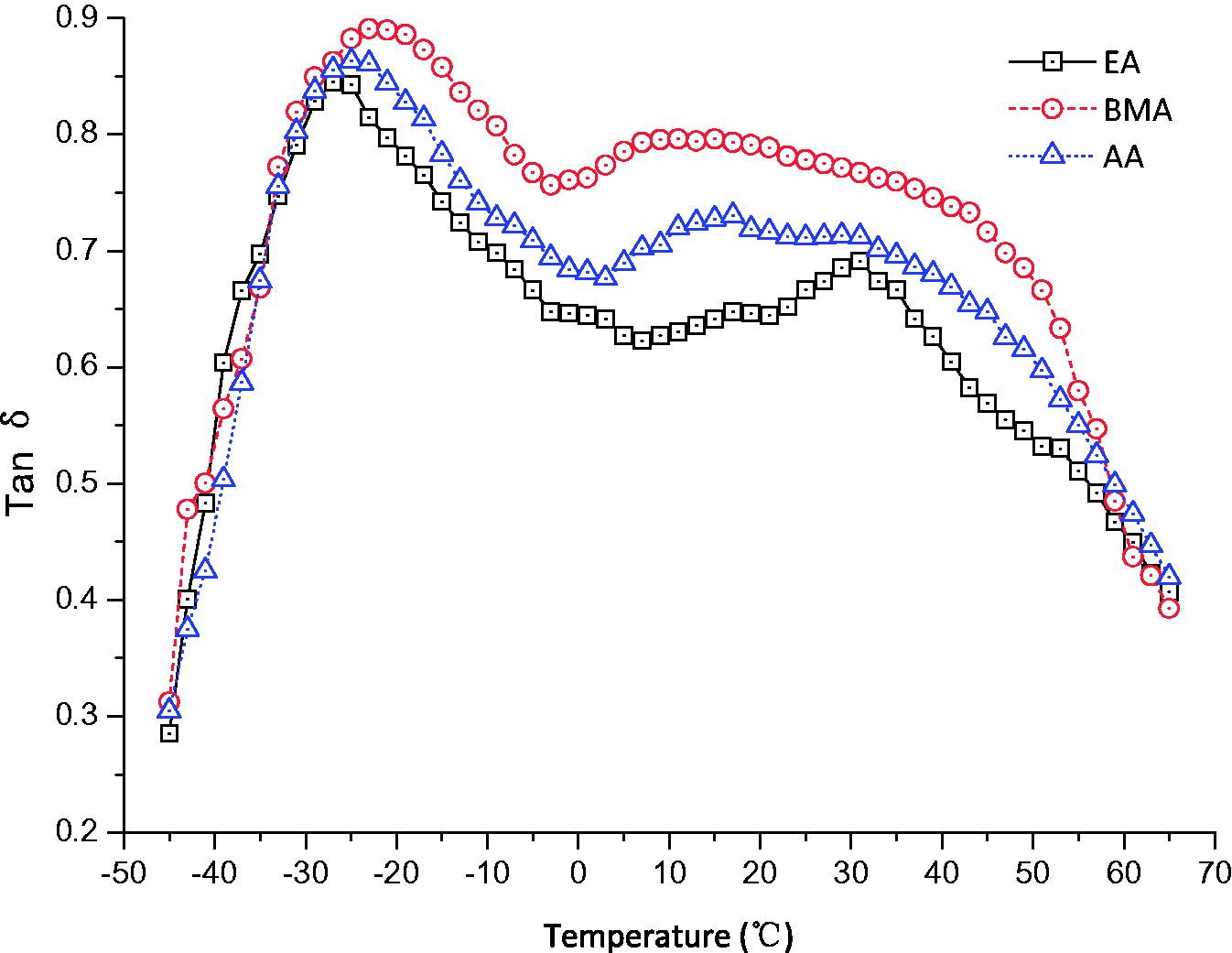
Loss tangent curves of PU/VER IPNs with different VER comonomers vs. temperature (40 Hz).
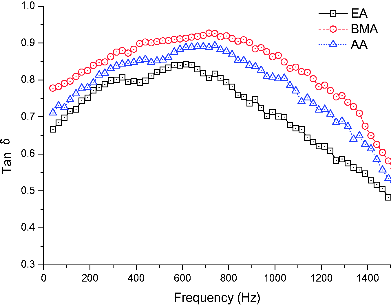
Loss tangent curves of PU/VER IPNs with different VER comonomers vs. frequency (25°C).
The results can be attributed to two factors. The first factor is the aforementioned fact that the compatibility between the networks is a key factor affecting the damping properties of an IPN. The solubility parameter difference of PAA and PU is smaller than that of PEA and PU, so the compatibility of the PU/VER (AA) IPN is better than that of the PU/VER (EA) IPN. It is followed by the PU/VER IPN with AA as the VER comonomer. PU/VER IPN with EA as the VER comonomer have the fewest butyl ester groups.
The influence of component ratios (the component ratio of PU and VER by weight)
It can be concluded from the first test group that the PU/VER (BMA) IPN is the best choice for the rail damper in terms of damping material. As mentioned earlier, the component ratio of PU and VER by weight is another factor which plays an important role in determining the damping performance of a PU/VER IPN. Thus, to further improve the damping properties of PU/VER (BMA) IPN, the second study group was designed with three different component ratios of 80:20, 60:40 and 40:60 to find the optimal component ratio.
Figure 7 provides information about the relationship between the loss tangent and temperature of PU/VER (BMA) IPN with different component ratios. As shown, the 80:20 IPN has the best damping properties between −40°C and 45°C. The two peaks, corresponding to the glass transition temperature of pure polymers PU and VER, nearly form a broad peak which shows that the hard phase component has poured into the soft phase component and considerable entanglement at the molecular level is formed in the networks. The damping properties of the IPN with the component ratio of 40:60 are comparatively poor because of the two obvious damping peaks and low tan δ values between them. This also implies that the degree of compatibility of PU/VER (BMA) IPN is relatively low under this condition. And the damping properties of the IPN with a component ratio of 60:40 are better than the IPN with a component ratio of 40:60, but worse than the IPN with a component ratio of 80:20 between −40°C and 45°C.
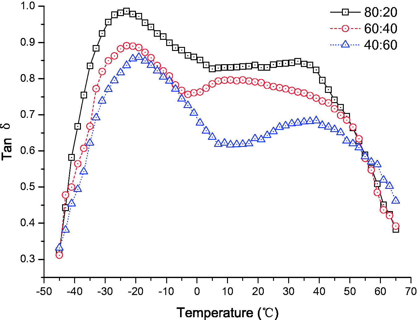
Loss tangent curves of PU/VER IPN with different component ratios vs. temperature (40 Hz).
Figure 8 indicates the plots of the loss tangent versus frequency of PU/VER (BMA) IPN with different component ratios at 25°C. As can be observed, PU/VER (BMA) IPN with a component ratio of 80:20 has the best damping properties, followed by that with a component ratio of 60:40. The PU/VER (BMA) IPN with a component ratio of 40:60 exhibits the worst damping performance. The optimal component ratio was applied in the test discussed in the next section.
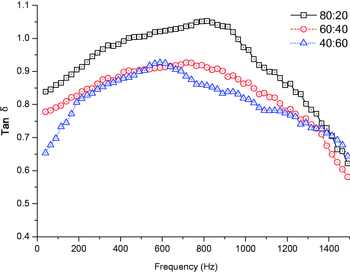
Loss tangent curves of PU/VER IPN with different component ratios vs. frequency (25°C).
The influence of organic hybrid material
The effect of N-dicyclohexyl-2-benzothiazole-sulphenamide (DZ) was also investigated as another method of improving the damping performance of PU/VER (BMA) IPN. The third group was studied with three gradations of DZ content component ratio, namely, 0%, 15%, and 30% (the component ratio of DZ to PU and VER by weight). Figure 9 reveals the relationship between the loss tangent versus temperature of PU/VER (BMA) IPN and the content of DZ at 40 Hz. From the figure, three important results can be found. First, the loss tangent curves have two pronounced “peaks” before and after the mixing of DZ, which means that DZ is compatible with PU and VER. Second, the “valley” between the two pronounced “peaks” becomes more and more flat with the increase in DZ content, indicating that the primary semi-compatible IPN system turns to a compatible system after the application of DZ. Finally, with more additions of DZ, the high damping temperature range moves towards the higher temperature, which demonstrates the total intermolecular forces among different matrices are becoming increasingly stronger with the increase of DZ content. In this study, the optimal DZ content for the damping performance of PU/VER (BMA) IPN is 30%.
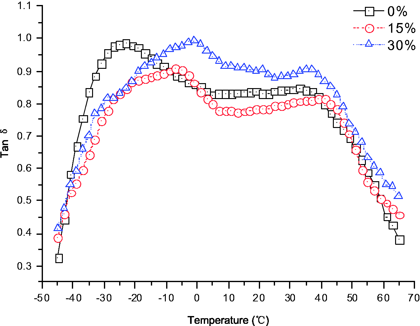
Loss tangent curves of PU/VER IPN with different content of DZ vs. temperature (40 Hz).
Figure 10 shows the relationship between loss tangent versus frequency of PU/VER (BMA) IPN and content of DZ at 25°C. As it can be observed, PU/VER (BMA) IPN with a DZ component ratio of 30% has the optimal damping properties between 40 and, 1500 Hz. The optimal results were applied in the structural form improvement tests and field test discussed in the following section.
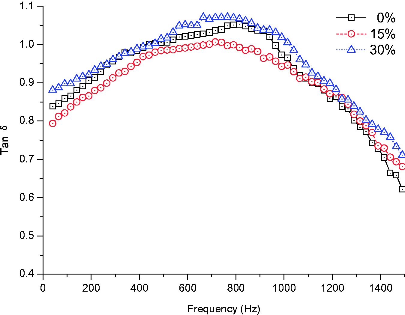
Loss tangent curves of PU/VER IPN with different content of DZ vs. frequency (25°C).
Structural improvement
The installation method for the slotted stand-off layer damper discussed in the first part of the research is as shown in Figure 11(a). Practice has shown that it is relatively difficult to install and remove the slotted stand-off layer damper in situ. The problem mainly lies in the lower part of the damper. This can lead to aberrations that are very difficult to remedy and gaps between the rail and damper that are difficult to fill because of the inevitable manufacturing errors. Hence, to improve the applicability of the damper, relative improvement measures were proposed, as shown in Figure 11(b). These include cutting off the lower part of the damper covering the rail foot and enlarging the length of the damper thus enlarging the area of the rail web covered by damper.
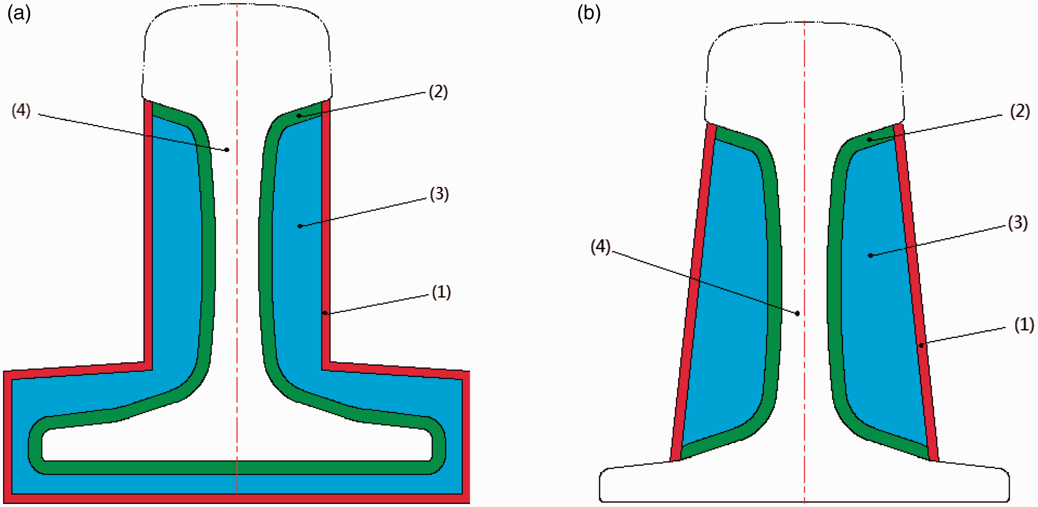
Schematic plot of a rail with different damper. (a) Rail with slotted stand-off layer damper. (b) Rail with semi-slotted stand-off layer damper.
Both the slotted stand-off layer damping treatment and the semi-slotted stand-off layer damper are arranged according to the special structure of the rail, as depicted in Figure 11(a) and (b). This consists of four major parts: constrained layer of uniform thickness (1), a slotted stand-off layer (2) with uniform thickness connected to the rail, a variable-thickness damping layer (3) sandwiched between the slotted stand-off layer and the constrained layer, and the rail (4) surrounded by the stand-off layer. A strong adhesive made of polyurethane is applied to each layer.
In situ test
The benefit and applicability of the further improved slotted stand-off layer damper in reducing railway noise was investigated. This section describes the result of a test executed on a conventional metro with ballastless track, as one of the tests executed on commercial lines to estimate the practical vibration and noise reduction effects. The in-situ test consists of two parts, namely the track decay rate test and the noise measurement.
Installation of the rail dampers and test method
The selected test site is a curved operational track inside a tunnel with a 400 m radius on Chengdu Metro Line 4, where high levels of rail vibrations in both vertical and lateral directions are induced, and therefore the radiated wheel-rail noise is loud. The slotted stand-off layer dampers and semi-slotted stand-off layer dampers were installed over a length of approximately 100 m on the same site, in turns. The DT-III fastening system is used in this line and the vertical static stiffness of this fastening system is 21–25 kN/mm. The ballastless bed is the common integrated bed. The temperature during the vibration and noise measurements in the tunnel was 25°C.
The track decay rate is a crucial parameter determining rail noise radiation. For rails having a low decay rate, train-induced vibration can propagate for a long distance along the rail and radiate noise, which is often referred to as a “singing rail”. The rail dampers can increase the track decay rate, thus reducing the effective noise radiation length. Thus, the track decay rate was chosen to evaluate the vibration and noise reduction effect of the further improved slotted stand-off layer damper. The specific accelerometer layout and test implementation in this study followed European Committee for standardization. 19 Figure 12 illustrates a view of the track without dampers, installed with semi-slotted stand-off layer dampers and slotted stand-off layer dampers. The track without dampers was measured first, followed by the same track with semi-slotted stand-off layer dampers, and finally the same track with slotted stand-off layer dampers after the semi-slotted stand-off layer dampers were removed.
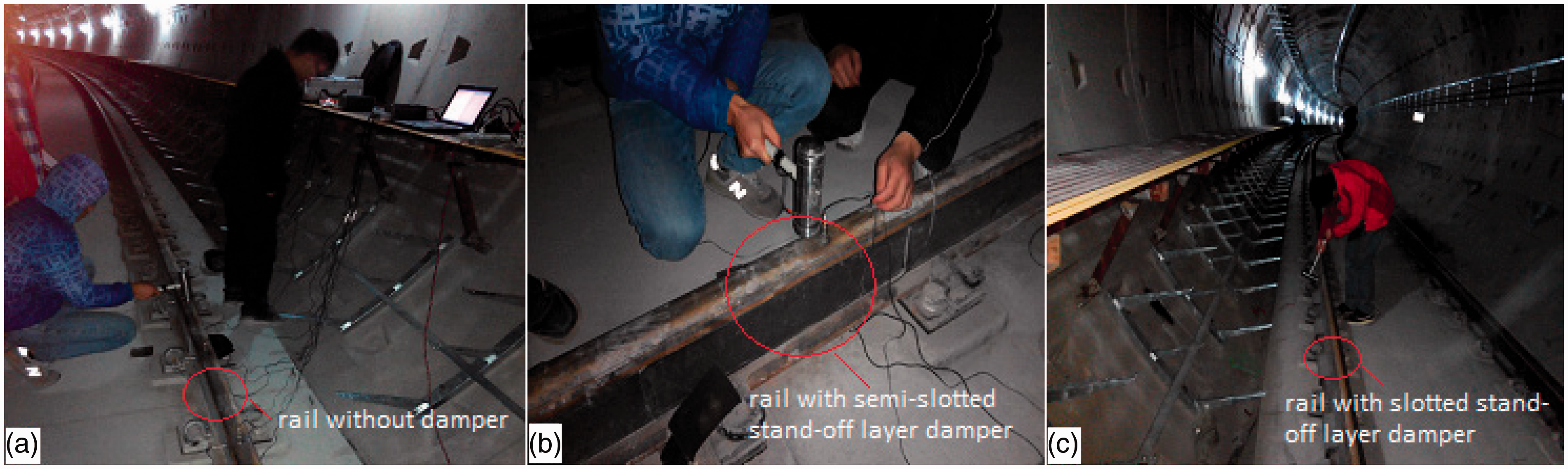
View of the track without dampers and with different types of rail dampers. (a) Rail without damper. (b) Rail with semi-slotted stand-off layer damper. (c) Rail with slotted stand-off layer damper.
Further, in this paper, the noise results when trains passed were measured, and the microphone positions S1 and S2 were both set in the middle of the section, approximately 2.0 m away from the near side track center and approximately 1.0 m above the ground level, as shown in Figure 13(a). The two measuring points are 1.2 m apart along the longitudinal railway direction. Two standard microphones measured noise when trains passed the measuring points as shown in Figure 13(b). Every measurement was repeated 10 times. The measured vehicles in this study are B type metro trains. The train is disc-braked and composed of two electric locomotives and four trailer cars. The length of the vehicle is 19 m and the overall length of the B type metro train is 114 m. The running speed of the train is 60 km/h. The measurements were made in the same measuring section and carried out as follows, first measuring the noise without dampers, then with semi-slotted stand-off layer dampers, and finally with the slotted stand-off layer dampers.
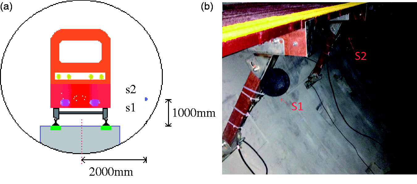
Noise measuring points on the in-situ test. (a) Vertical sketch view of measuring point positions. (b) Experimental setup of the measuring points.
Results and discussion
Track decay rate test results
As noted, the rate of decay of vibration along the rail, usually expressed in dB/m, is the main parameter influencing the medium-high frequency vibration of the rail and the amount of noise radiated by the rail. 20 In the case of the vibration and noise reduction capacity of the further improved slotted stand-off layer dampers studied in this research, the comparison of the measured decay rates of the three different tracks are shown in Figures 14 and 15 according to the method described in European Committee for standardization. 19
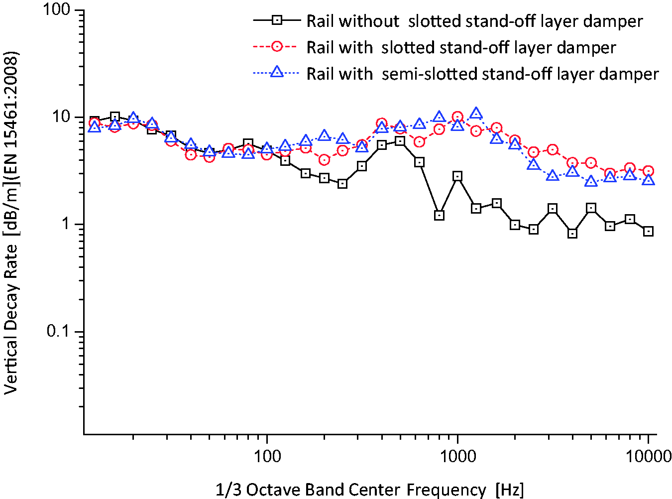
Measured vertical track decay rate with and without different rail dampers.
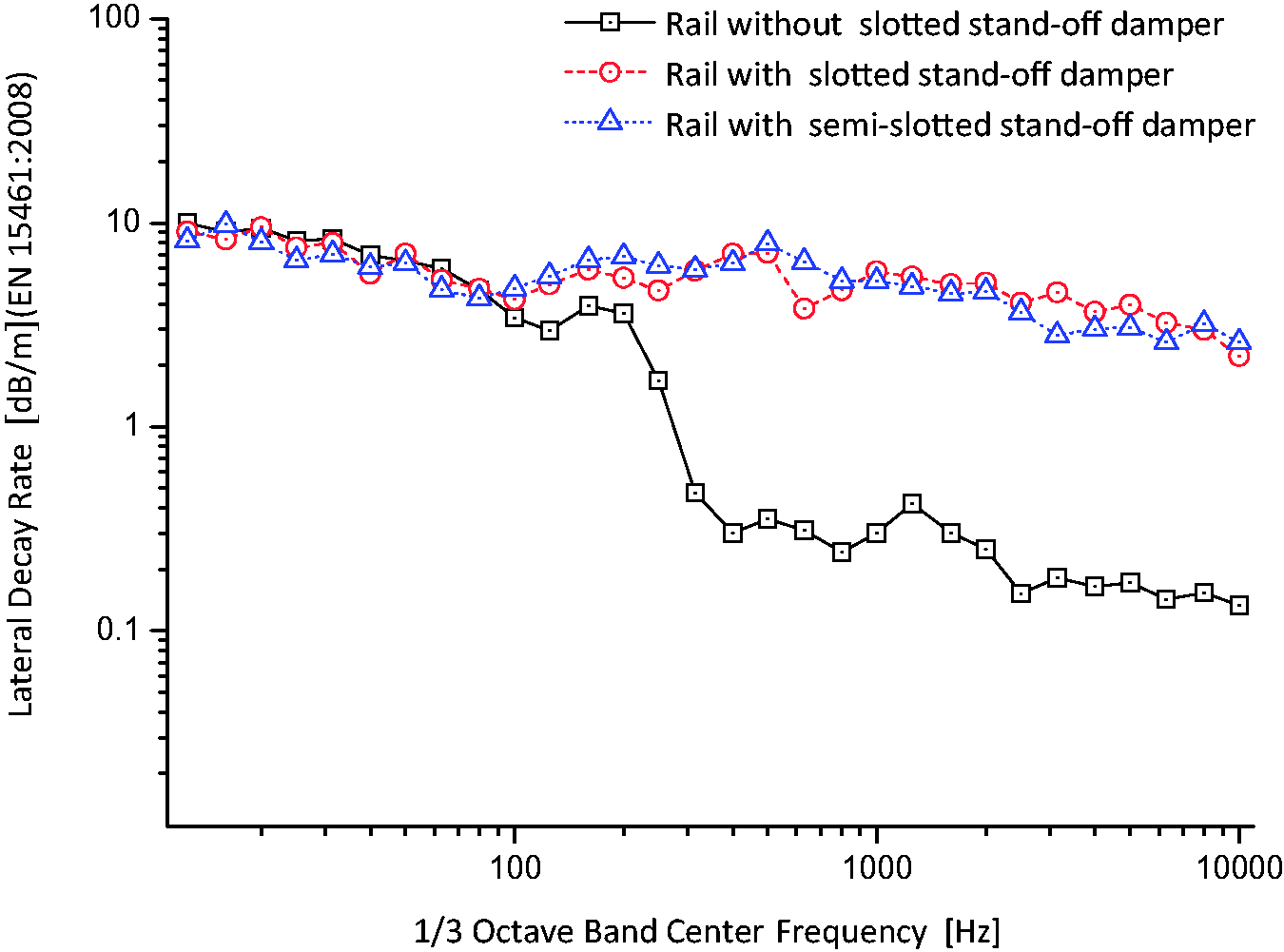
Measured lateral track decay rate with and without different rail dampers.
It is clearly demonstrated in Figure 14 that, in general, the vertical track decay rates at frequencies above 100 Hz are widely increased after the installation of the two types of dampers, indicating that a slotted stand-off layer damping treatment system is a very effective measure to control the medium-high frequency vibrations of the rail. Moreover, the vertical decay rate of the track with the slotted stand-off layer dampers (shown as the red curve relative to the track, the black curve is without rail dampers) was significantly increased from 0.9–6.0 dB/m to 3.0–10.1 dB/m above 160 Hz. The average increase is from 2.2 to 5.7 dB/m; the maximum increase is from 6.0 to 10.1 dB/m. The vertical decay rate of the track with the semi-slotted stand-off layer dampers (shown as the blue curve relative to the track without rail dampers) was significantly increased from 0.9–6.0 dB/m to 2.5–10.7 dB/m above 160 Hz. The average increase is also from 2.2 to 5.7 dB/m, while the maximum increase is from 6.0 to 10.7 dB/m. This shows that the improvement of the damper structural style does not weaken its original vibration reduction effect.
The lateral track decay rates with and without different rail dampers are shown in Figure 15. It can be observed that the lateral track decay rates are noticeably enhanced for the dampers at frequencies above 100 Hz. This is especially observed in the frequency range 250–10,000 Hz, where the average increase is from 0.7 to 4.8 dB/m for the slotted stand-off layer dampers (shown as the red curve) and also from 0.7 to 4.8 dB/m for the semi-slotted stand-off layer dampers (shown as the blue curve), compared with the track without dampers (shown as the black curve).
The rise in both the vertical and lateral track decay rates in the measurement towards 100 Hz is due to the part of the vibration energy that is transmitted to the dampers and is ultimately dissipated in the form of heat by the developed broad temperature and frequency range of PU/VER (BMA) IPN damping materials. And the lack of improvement below 100 Hz is simply due to the fact that the initial decay rates are very high due to the blocking effect of the rail support stiffness. On the other hand, when comparing the decay rate when using slotted stand-off layer dampers with that for semi-slotted stand-off layer dampers, it can be found that the differentiation of decay rates was negligible below 10,000 Hz. This is because the effect of the enlarged volume in size of the damper-covered rail web counterbalanced the cutting of the lower part of the damper-covered rail foot. In general, the increase of the decay rate with dampers is very helpful in reducing the medium-high frequency vibration of the rail and the noise radiated by the rail. In addition, it can be concluded that dampers increase the level of damping much better in the lateral direction.
Railway noise reduction test results
The noise reduction performance of the two types of dampers was also investigated through experimental tests on the track in the field. Figure 16 shows the average results measured by microphones at point S1 and S2 as the test car passed through. From Figure 16, it can be seen that both dampers could reduce the total noise level by up to 6 dB between 250 Hz and, 5000 Hz. This demonstrated that the damping materials developed from PU/VER (BMA) IPN had a fine damping performance and were ideally situated for rail vibration and noise control. Additionally, the vibration and noise reduction effect of the semi-slotted stand-off layer dampers and slotted stand-off layer dampers is almost the same, further indicating that the improvement of the damper structural style was very successful.
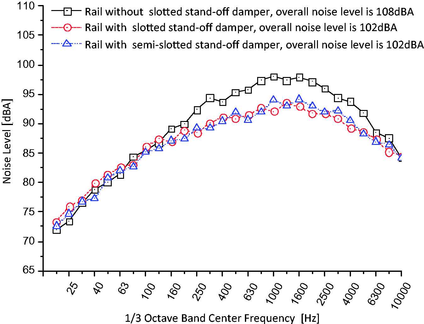
Result of one-third octave band analysis of noise.
Furthermore, it can be seen that the reduction of noise is especially remarkable between 630 Hz and 1600 Hz. There are two possible reasons for this. One reason is that according to the previous studies on railway vibration and noise, it is presumed that the contribution of noise radiated from the rail is dominant in the trackside noise between approximately 450 Hz and 2000 Hz. The other reason is the PU/VER (BMA) IPN damping materials had the best damping performance over this frequency range. Taking these factors into consideration, it can be demonstrated that this result verifies that the slotted stand-off layer dampers and semi-slotted stand-off layer dampers have a favorable effect in reducing the noise radiated from the rail. Moreover, the field installation and replacement experience has shown that the semi-slotted stand-off layer dampers are more convenient to install and remove than the slotted stand-off layer dampers. This also indicates that the benefits from the rail dampers were improved.
Conclusions
It has been demonstrated that rolling noise often dominates the lateral railway noise at speeds between 40 and 270 km/h. As an important component of the rolling noise, the rail radiated noise is derived from rail vibration, and therefore led to the development of the slotted stand-off layer damper with VER-IPN damping materials in the previous study. Nevertheless, by considering the actual spectral characteristics of the rail vibration, in the frequency range from 40 to 1500 Hz, under the temperature ranges from −45°C to 65°C in China and the requirements of simple operation, the aim of this work was to further improve the benefit and applicability of slotted stand-off layer damper in reducing railway vibration and noise.
The damping layer is the main vibration energy dissipation component of the slotted stand-off layer damper, and its energy dissipation capacity is heavily dependent on the material it is made of. Hence, in order improve the benefit of the rail damper, PU/VER IPN damping material, which has quite effective damping performance over the broad temperature and frequency ranges, was applied. Furthermore, the optimal PU/VER IPN damping materials with BMA as VER comonomers, with the component ratio of PU and VER of 80:20 by weight, and with DZ component ratio of 30%, have been experimentally determined by a series of tests carried out on some samples.
After determining the damping material, the applicability of the rail damper was also investigated by converting the slotted stand-off layer dampers into semi-slotted stand-off layer dampers, specifically by cutting off the lower part of the damper covering the rail foot and enlarging the volume of the damper part covering the rail web.
Then, the findings from the laboratory study were applied to make further improved rail dampers that were arranged in a test section on a conventional metro line. The results show that the vertical and lateral track decay rates at frequencies above 100 Hz are widely increased after the installation of the two types of dampers and that both types of dampers could reduce the total noise level by up to 6 dB between 250 Hz and 5000 Hz. However, the benefit of the improved semi-slotted stand-off layer dampers is much better than the previously discussed slotted stand-off layer dampers.
As a result, a proper semi-slotted stand-off layer damper that reduces rail vibration and noise has been designed, manufactured, and tested; and hence, the objective of this study was met. These results indicate that significant noise reduction can be achieved by using properly designed semi-slotted stand-off layer dampers. This methodology can be applied to similar problems of structural noise in civil engineering.
It is well known that even the best quality viscoelastic damping materials will perish with age, so it is necessary to study the change of damping properties of PU/VER (BMA) IPN materials with age under actual operation conditions. For this, further investigations are being conducted to study the reduction of rail vibration and noise with semi-slotted stand-off layer rail dampers.
Footnotes
Acknowledgments
The results and opinions presented are those of the authors and do not necessarily reflect those of the sponsoring agencies. The authors appreciate the cooperation for the development of damping material received by Hu Ji and Chengdu Feitelong Track New Materials Technology Co., Ltd.
Declaration of conflicting interests
The author(s) declared no potential conflicts of interest with respect to the research, authorship, and/or publication of this article.
Funding
The author(s) disclosed receipt of the following financial support for the research, authorship, and/or publication of this article: the National Natural Science Foundation of China, No. 51508479 and Research Fund for key research and development projects in Sichuan Province (2017GZ0373).