
Abstract
Thermal overstressing as a result of miniaturization is the foremost challenge for the next generation electronic devices. Shrinking size of electronic devices makes this problem even worse. Conventional cooling module which uses fan and a heat sink seems to be inadequate for cooling of electronic devices due to space constraints and higher circuit densities. Synthetic jet is a novel flow technique which synthesizes stagnant air to form a jet and is potentially useful for cooling applications. It results from periodic oscillations of a diaphragm in a cavity such that there is no net mass addition to the system. It is being recently researched as an effective alternative to fan but the existing rules on noise emissions constitute an impediment to the practical use of synthetic jet. Besides several nonauditory health effects, prolonged exposure to high levels of noise can cause noise-induced hearing loss. To adopt ameliorative solutions and for adherence to legislative regulations, it is essential to assess the noise exposure. Present study is embarked on to investigate the effect of excitation frequency and voltage on sound pressure level of synthetic jet for orifices of different diameter and thickness. This jet acoustic research is performed in an imperative and controlled acoustic environment, i.e. acoustic test chamber. Spectrum analysis clearly indicates impedance mismatch between audio amplifier and electric transducer used to generate the jet flow. Over the past few years extensive experimental and analytical results have led to good understanding of synthetic jet but study on impedance mismatch has always been elusive. The results on synthetic jet heat transfer, flow, and acoustic characteristics cannot be faithfully reproduced due to such hurdle. In order to vanquish or conquest over it, matching the impedance between source and the load is inevitable. The conclusion of this paper unveils the necessity of impedance matching for high fidelity measurements of synthetic jet.
Introduction
There is a lot of concern in the electronics industry about thermal management. The new generation electronic devices suffer from thermal problems due to miniaturization and more features leading to increased temperatures on one hand, while on the other hand the customer expects higher reliability and less noise. Also, new processors are consuming more power, circuit densities are getting higher, and there is obligation to reduce the size of devices. Because of this heat dissipation levels of electronics devices continue to increase. Consumer-oriented systems still focus on air cooling approaches due to simplicity and ease of implementation. Unless there is a breakthrough in low-power systems, conventional fan-driven cooling will no longer be enough. Processors, memory chips, graphics chips, batteries, radiofrequency components, and other devices in electronic equipment generate heat that must be dissipated to avoid damage. Traditional cooling techniques use metallic heat sinks to conduct thermal energy away from the devices and then transfer it to air being circulated by fans. In order to achieve increased local power dissipation levels with conventional fan heat sink configurations, designers are forced to use higher speed fans which result in noise and reliability issues.
However, cooling fans have a number of limitations. For instance, much of the circulated air bypasses the heat sinks and does not mix well with the thermal boundary layer that forms on the fins. Fans placed directly over heat sinks have “dead areas” where their motor assemblies block air flow. And as designers boost air flow to increase cooling, fans use more energy, create more audible noise, and take up more space.
Over the last decade synthetic jets have been researched as an alternative to fans as air moving devices and have been shown to be highly effective for cooling of electronics devices. Synthetic jets are formed by time-periodic, alternate suction and ejection of fluid through an orifice bounding a small cavity, by the time periodic motion of a diaphragm that is built into one of the walls of the cavity. Unlike conventional jets, synthetic jets are “zero-mass-flux” in nature and produce fluid flow with finite momentum with no mass addition to the system and without the need for complex plumbing. 1
Literature survey
An extensive literature survey is carried out to garner the information about basic working, flow, and heat transfer characteristics of synthetic jet. They are observed to be more profound; however, acoustic study of synthetic jet is always found to be marginalized and needs a serious attention for its prolific applications.
Smith and Glezer 1 discussed the formation and evolution of the two-dimensional synthetic jet through Schlieren imaging and velocity measurements. In their study plane turbulent jets having finite streamwise momentum were synthesized normal to an orifice in a flat plate by a train of vortex pairs. The vortices were formed at the edge of an actuator orifice without net mass injection by the motion of a diaphragm in a sealed cavity. According to Gil and Strzelczyk 2 zero net mass flux (ZNMF) is the descriptor of device with no net mass transfer but at the same time finite amount of momentum transfer to the ambient fluid. They have elaborated working of synthetic jet as an integration of mass flow rate across orifice over integer number of cycles is equal to zero. When transducer is actuated by means of power oscillator, the fluid is expelled through the orifice, boundary layer separates, and vortex rings are formed. Due to self-induced velocity, vortex rings propagate away from orifice and are detached. During subsequent suction stroke, ambient fluid is drawn into cavity as shown in Figure 1.
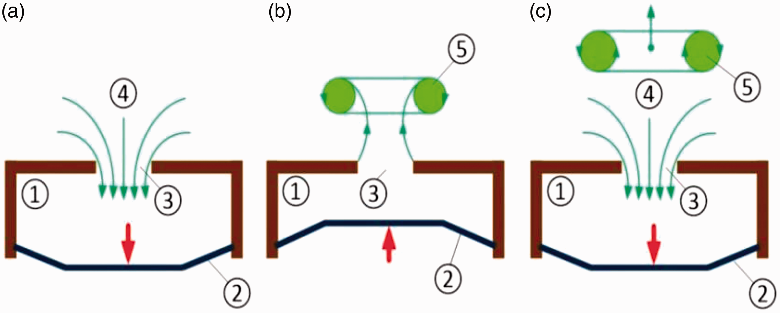
Schematic of synthetic jet: (a) Suction stroke, (b) vortex ring generation during ejection stroke, and (c) propagation of vortex ring away from orifice. 2 1: cavity, 2: diaphragm, 3: orifice, 4: sucked fluid, 5: vortex ring.
Mallinson et al. 3 investigated experimentally and computationally the flow generated by a synthetic jet actuator with a circular orifice. An experimental investigation to determine the structure and mean flow quantities of round ZNMF jets is reported by Cater and Soria. 4 Those jets were generated by a piston oscillating in a cavity behind a circular orifice. They observed different flow patterns with dye flow visualization. Cross-correlation digital particle image velocimetry (PIV) was used to measure instantaneous two-dimensional in-plane velocity fields in a plane containing the orifice axis. Using the numerical simulations, Utturkar et al. 5 examined the sensitivity of synthetic jets to design of the jet cavity. Their primary focus was to examine the effect of changes in the cavity aspect ratio and the placement of piezoelectric diaphragm on the flow produced by the jet.
Experimental measurements and flow visualization of synthetic jets and continuous jets are reported by Smith and Swift. 6 Measurements of synthetic jets are compared with the same Reynolds number. In the far field, the synthetic jets bear much resemblance to continuous jets. However, in the near field, the synthetic jets are dominated by vortex pairs that entrain more fluid than continuous jet. The efficiency of synthetic jet impingement cooling and the mechanisms associated with the removal of heat from a constant heat flux surface were investigated experimentally using thermocouples and PIV by Pavlova and Amitay. 7 They investigated the effects of jet formation frequency and Reynolds number at different nozzle-to-surface distances and compared to continuous impingement jet cooling. In their experiments, the synthetic jet was operated at two separate frequencies, 420 and 1200 Hz, which were found to be the most effective for the Reynolds number range used in terms of the heat removal improvement. They also found that for small distances between the synthetic jet and the heated surface, the high formation frequency (f = 1200 Hz) synthetic jet removes heat better than the low frequency (f = 420 Hz) jet, whereas the low-frequency jet is more effective at larger distances. They have also conducted PIV measurements of the synthetic jet velocity fields in order to understand the different flow mechanisms associated with heat removal from the surface by synthetic jets at the two operating frequencies. Tan and Zhang 8 discussed the utility of a synthetic jet driven by piezoelectric actuator for impingement on a heated surface. In addition, they have used PIV, hot wire anemometer to measure the jet velocity field to describe characteristics and flow field database of the synthetic jet.
Chaudhari et al. 9 studied the impingement heat transfer characteristics of a synthetic jet in their work. Toward the end, the behavior of the average heat transfer coefficient of the impinged heated surface with variation in the axial distance between the jet and the heated surface was measured. In addition, radial distribution of mean and rms velocity and static pressure were also measured. Experiments were conducted for a wide range of input parameters: the Reynolds number (Re) was in the range of 1500–4200, the ratio of the axial distance between the heated surface and the jet; to the jet orifice diameter was in the range of 0–25, and the length of the orifice plate to the orifice diameter varies between 8 and 22 in their study. The maximum heat transfer coefficient with the synthetic jet was found to be up to 11 times more than the heat transfer coefficient for natural convection. Chaudhari et al. 10 experimentally investigated the effect of shape of the orifice of a synthetic jet assembly on impingement cooling of a heated surface. They considered different shapes of orifice such as square, circular, and rectangular of different aspect ratios (in the range of 1–20) and hydraulic diameters (3.8–8 mm). The average heat transfer coefficient as a function of the distance between the orifice and the heated surface was obtained. The Reynolds number (Re) was in the range of 950–4000 based on average velocity, while the normalized axial distance varied between 1 and 25. The heat transfer enhancement with a square orifice was found to be larger than that with rectangular and circular shapes at larger axial distances z/d > 5, for the same set of boundary conditions. It was also found that rectangular orifice with aspect ratio between 3 and 5 gave best performance at smaller axial distances. The experimental setup used is shown in Figure 2. Experimental work carried out by Gunjan Verma, 11 a student of Indian Institute of Technology, Bombay during MTech course is particularly important to study flow visualization and near-field heat transfer measurements of synthetic jet.
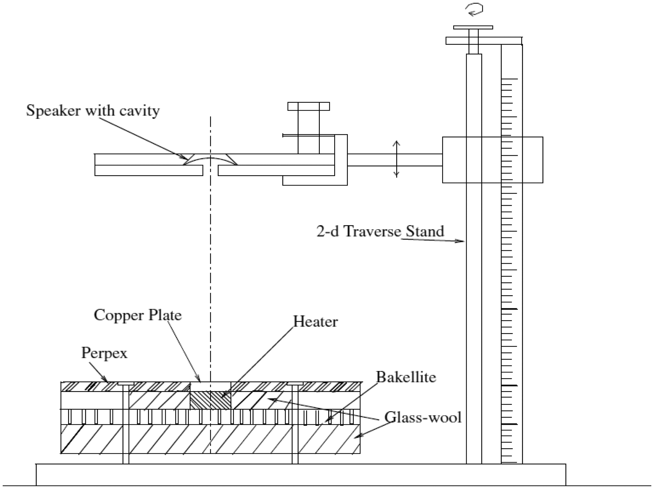
Experimental setup for heat transfer measurements. 10
From the above literature survey, it is observed that a lot of researchers have put their endless efforts to design, investigate, and optimize synthetic jet flow. It is needless to say that researchers have succeeded to a great extent to generate synthetic jet flow for cooling applications. However, from the inception of jet research, it is found to be confined to flow and a heat transfer characteristic until a paper by M. Arik is published. Arik 12 obtained a maximum level of 73 dB of synthetic jet in his experimental work and stated that it could be reduced to 30 dB by employing noise reduction technique. Bhapkar et al. 13 studied acoustic and heat transfer aspects of an inclined impinging synthetic jet. They have studied the effect of geometric and control parameters on the SPL of circular orifice synthetic jet. Though the work is novel, it has been found that they carried out acoustic measurements in a room and not in an acoustic chamber. 13 They have clearly published in the section 2.2 experimental setup for acoustic measurements that the acoustic measurements are conducted in a sufficiently large room. The size of sound-generating source (i.e. acoustic actuator) is very small as compared to the room size. Other sound-generating sources are deliberately kept off during the tests, due to which room environment during performing the experiments was calm; hence, background noise is negligibly low. The measurement region is isolated from other sound-generating sources.13 Actually, an acoustic test chamber is imperative for precision acoustic measurements in order to suppress unwanted outside noise and minimize unnecessary inside reflections. In order to overcome this lacuna and to hone the acoustic results in this paper, first an acoustic test chamber is built by Kanase and Chaudhari, 14 for SPL measurement of synthetic jet. It is designed according to ISO 3745 along with hemispherical track, manufactured using multilayer absorption treatment and validated by using S/N, 1 W, 1 kHz, 1 m method and inverse square law-discrete traverse method. Experimentally the background noise is found to be 21 dB(A) as shown in Figure 3. It is less than noise in an empty auditorium or whisper at 1 m. 15
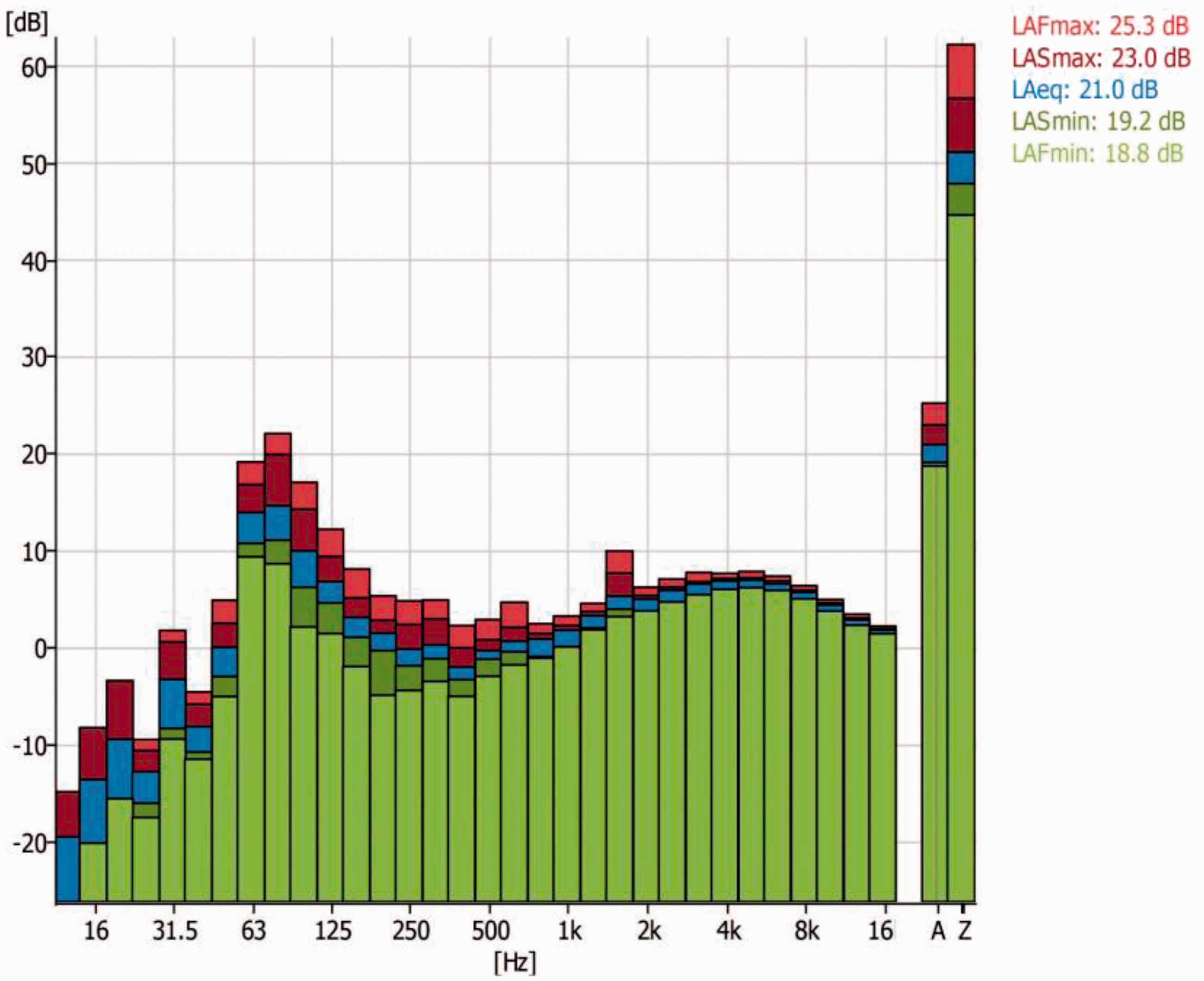
Spectrum obtained for background noise level. 14
In such a validated acoustic test, chamber acoustic experimentation of circular orifice synthetic jet is conducted. Details about the experimental setup and results can be found in subsequent sections.
Necessity of anechoic chamber
Sound pressure level (SPL) is a logarithmic scale hence 3 dB is a huge difference.
The rigid wall structure inhibits structural resonances and affects the SPL in the way that it does not act as a noise source itself when exterior pressure loads or structures excite vibrations of the walls. Sound waves propagating away from a source are reflected by room boundaries and barriers. The resulting sound field at the receiver consists of two parts:
Direct sound: Sound propagated directly from the source to the receiver and Reverberant sound: Sound that reaches the receiver after reflections from room.
Sound absorption treatment breaks the sound path and thus results into high noise reduction. Figures 4 and 5 show the total noise attenuation of 10.5 dB in measurement of SPL of 7 in. diameter loudspeaker with Acoustic Test Chamber at 1 kHz. Noise attenuation at the rest of frequencies can be observed from these spectrums.
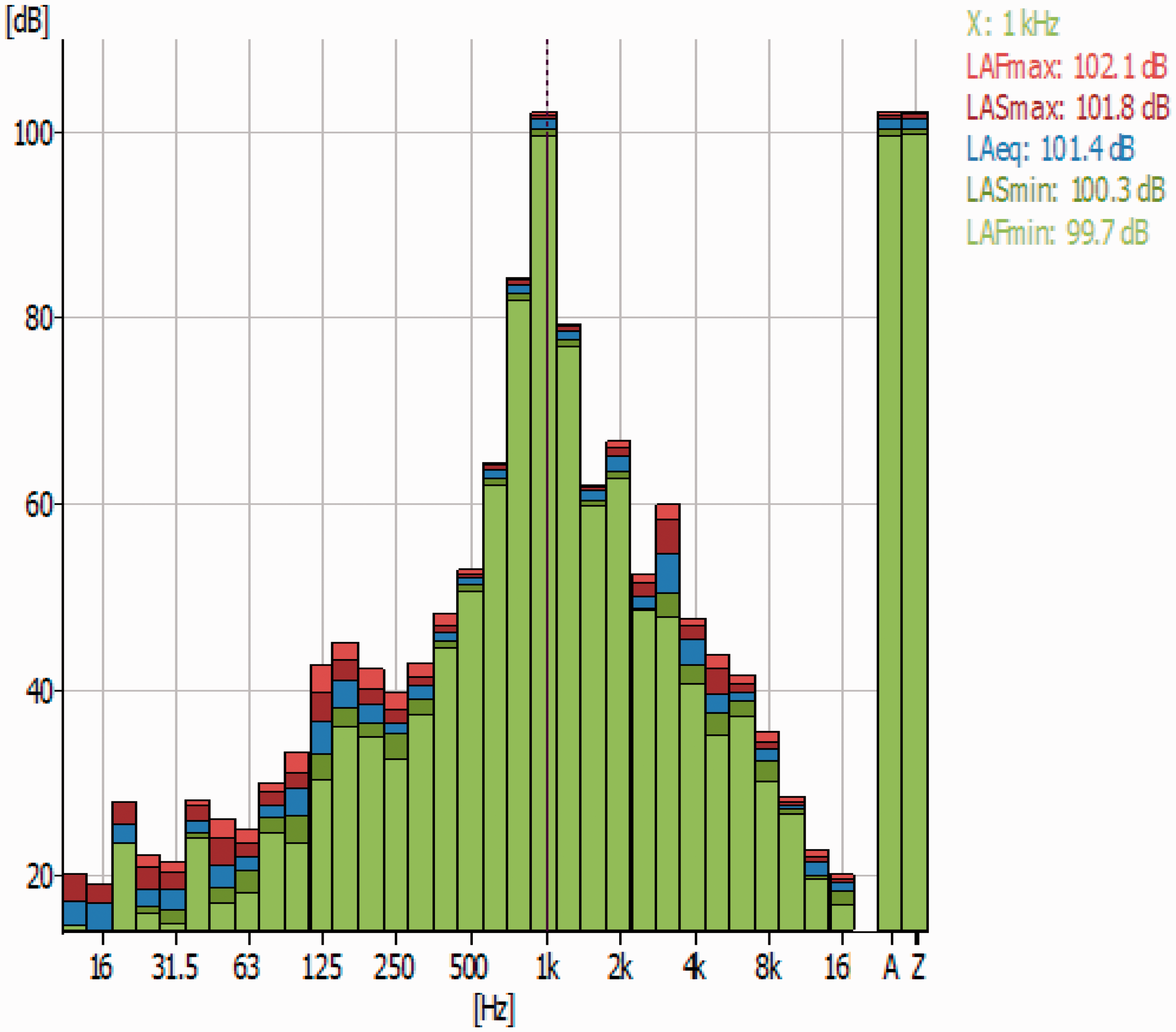
Sound spectrum for loudspeaker operating at 1 W, 1 kHz, 1 m outside acoustic test chamber.
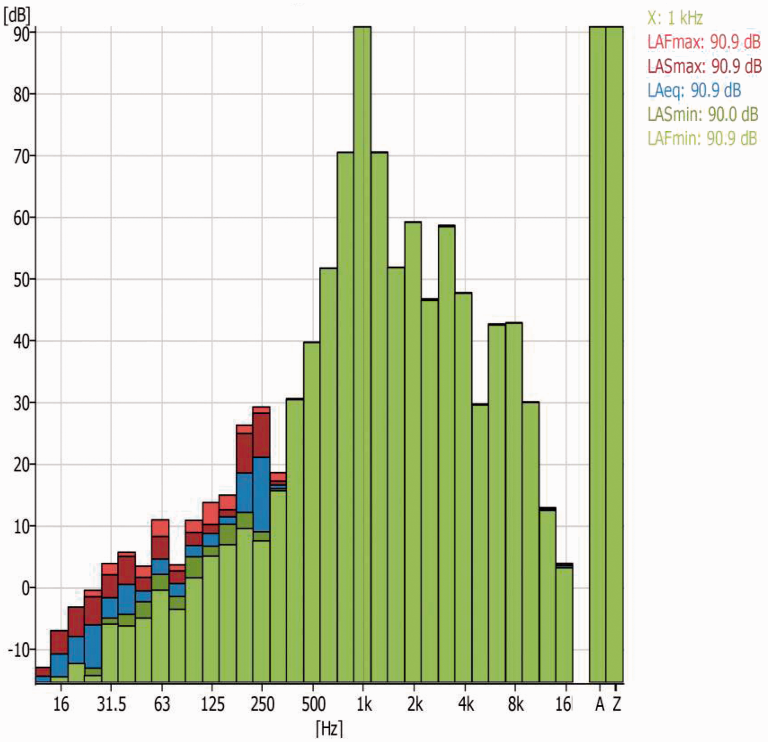
Sound spectrum for loudspeaker operating at 1 W, 1 kHz, 1 m inside acoustic test chamber.
Experimentation in an anechoic chamber
Pure tone viz. test tone of a radio at 1 kHz is a pure sine wave but most of sound waves in the nature are quasi-complex in nature. In other words, a pure tone with dominant acoustic energy at a particular frequency rarely exists in the nature. As such, it is imperative to design an acoustic test chamber for precision acoustic measurements. In the present study, a low-cost anechoic chamber having free working space of 2.28 m × 2.28 m × 1.1 m (7.48 ft × 7.48 ft × 3.68 ft) is designed according to ISO 3745. It is manufactured with multilayer absorption treatment by giving emphasis on Green Technology (Green Tech). Green Technology believes in “first to do no harm” so that the question of patch up or bandaging does not arise. It is based on the principle that it is better to prevent waste than to treat or clean after it is formed. An acoustic test chamber as shown in Figure 6 is placed in the Research Laboratory of Mechanical Engineering Department in Vishwakarma Institute of Technology, Pune where the ambient noise level of 50–60 dB is observed. The chamber performance has been assured by different methods of validation viz. S/N, 1 W, 1 kHz, 1 m and inverse square law (1/r2 or 6 dB/dd) and designed for investigating noise of sources having height up to 5 in. 14
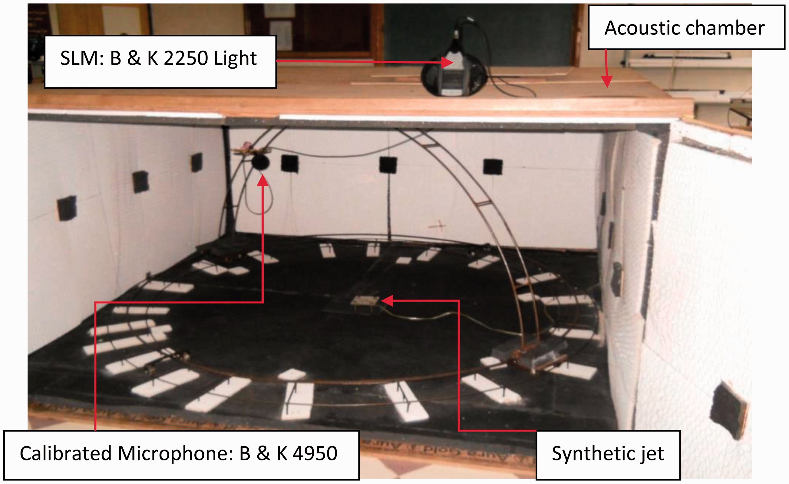
Acoustic test chamber and hemispherical track along with synthetic jet. 14 B & K: Bruel and Kajer; SLM: sound level meter.
Instrumentation for acoustic experiment.
As shown in Figure 5, for 7 in. diameter acoustic speaker actuated at 1 kHz the observed SPL is 21 dB higher than the rest of frequencies which enlightens accuracy of test chamber from acoustic viewpoint.
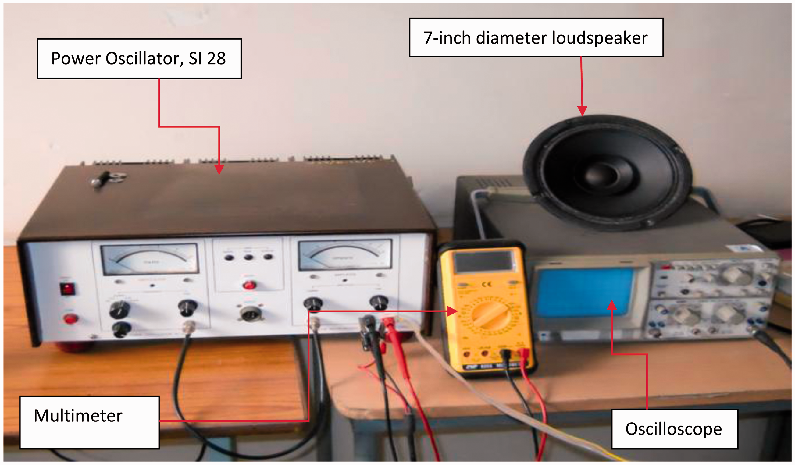
For the present experiment, air is the working fluid. An acoustic speaker of 2 in. in diameter, impedance of 8 Ω, and 0.5 W rated powers is used for creating the synthetic jet flow. As shown in Figure 7, a power oscillator (Syscon Instruments, SI 28) is used to excite and an oscilloscope (ScienTECH 201) is used to monitor the input to the synthetic jet. The power oscillator can independently control the frequency and excitation voltage to the synthetic jet.
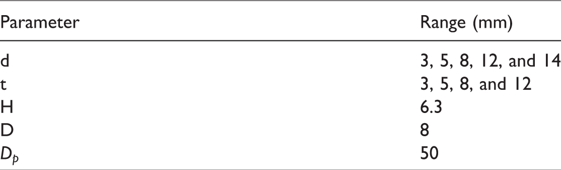
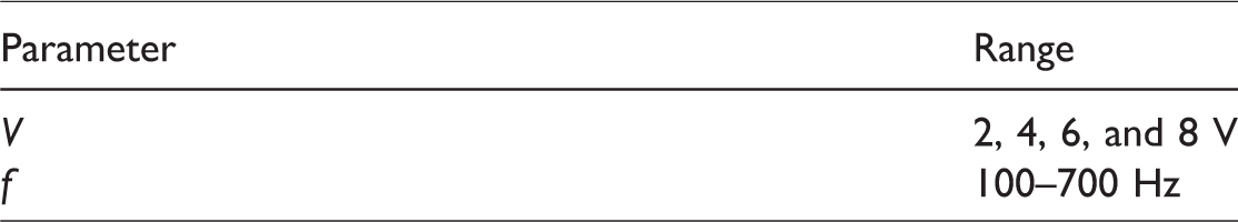
Chaudhari et al. 16 reported design aspects of synthetic jet cavity viz. geometric parameters and control parameters. Geometric parameters considered were cavity depth and actuator diameter along with orifice diameter and height. Control parameters considered were frequency and excitation voltage. They found upper and lower bound frequencies for the formation of jet and two resonance frequencies corresponding to the diaphragm frequency (250–300 Hz) and Helmholtz frequency (1200 Hz). In the present study, a constant cavity depth of 6.3 mm and actuator diameter of 50 mm are considered as up to the first resonance frequency exit velocity was found invariant and above this frequency weak dependence on cavity depth. Exit velocity was reported as a function of control parameters and orifice diameter. Deliberately, it has been decided to vary orifice diameter and orifice height (acrylic plate thickness) for a particular excitation voltage, i.e. 2 V for frequency range of 100–700 Hz and the same procedure is repeated for different voltages, i.e. 4, 6, and 8 V. It is worth enough to note that diameters of circular orifice considered are 3, 5, 8, 12, and 14 mm while orifice heights are 3, 5, 8, and 12 mm. Four important aspects have been studied viz. effect of orifice diameter on SPL, effect of orifice height on SPL, effect of excitation voltage on SPL, and effect of excitation frequency on SPL of circular orifice synthetic jet. Table 1 shows geometric parameters while Table 2 shows control parameters of synthetic jet.
Range of geometric parameters of synthetic jet.
Range of control parameters of synthetic jet.
Instrumentation
B & K type handheld analyzer 2250 light with sound level meter (SLM) software BZ-7130, 1/1 octave frequency analysis BZ-7131, 1/3 octave frequency analysis BZ-7132. Calibrated microphone: B & K type 4950 (Free field &½ in condenser microphone) with microphone preamplifier ZC-0032. Power oscillator (Syscon Instruments, SI 28) Oscilloscope (ScienTECH 201), multimeter CSE 8500 Voltmeter (MECO (0–20 V)), ammeter (Selec MA12).
Under realistic conditions of ambient noise the background noise level observed is in the range of 21–23 dB(A).
14
The corresponding background noise level is added as a correction for SPL measurement of synthetic jet.
Procedure for SPL measurement of synthetic jet
Abbasi et al. 17 used A-weighting system for the assessment of the effect of wind turbine noise on the general health of staff at Manjil wind power plant in Iran. The response of human auditory system is frequency dependent. In order to have a close match between objective measurements and subjective effects, A-weighted frequency weighting system is used. Synthetic jet SPL is measured with a Bruel and Kajer (B & K) type SLM with spectrum analyzer as shown in Figure 8 which consists of A-weighted SPL measurement system normally denoted as dB(A) or simply dB. A-weighted SPL discriminates the lower frequencies and closely matches with the human perception at different frequencies. So, it has been decided to use A-weighting system for SPL measurement of synthetic jet.
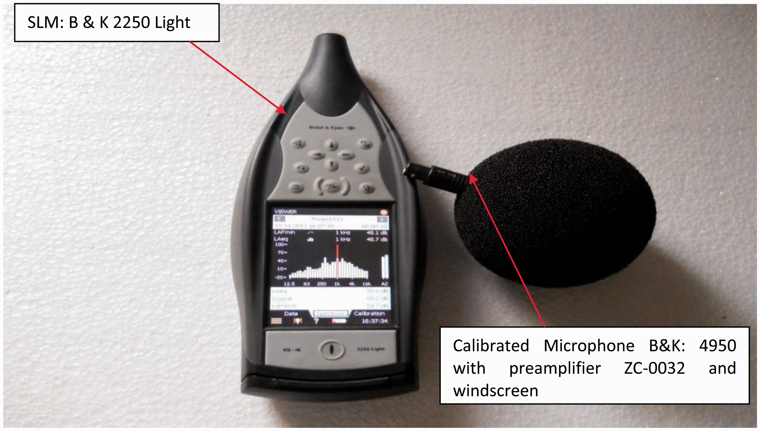
B & K type handheld analyzer 2250 light with BZ-7130, BZ-7131, BZ-7132 Spectrum Analysis Software. B & K: Bruel and Kajer; SLM: sound level meter.
SPL measurements at different microphone locations on hemisphere are taken to avoid the directivity effect of sound source as shown in Figure 9. Since synthetic jet has circular orifice shape under investigation, it is placed in a validated anechoic chamber with negligible spatial variation in SPL 14 and any jet radiates maximum noise in a direction inclined at an angle of 30° to the jet normal axis 15 ; it has been decided to locate microphone at point no. 2 (see Figure 9).
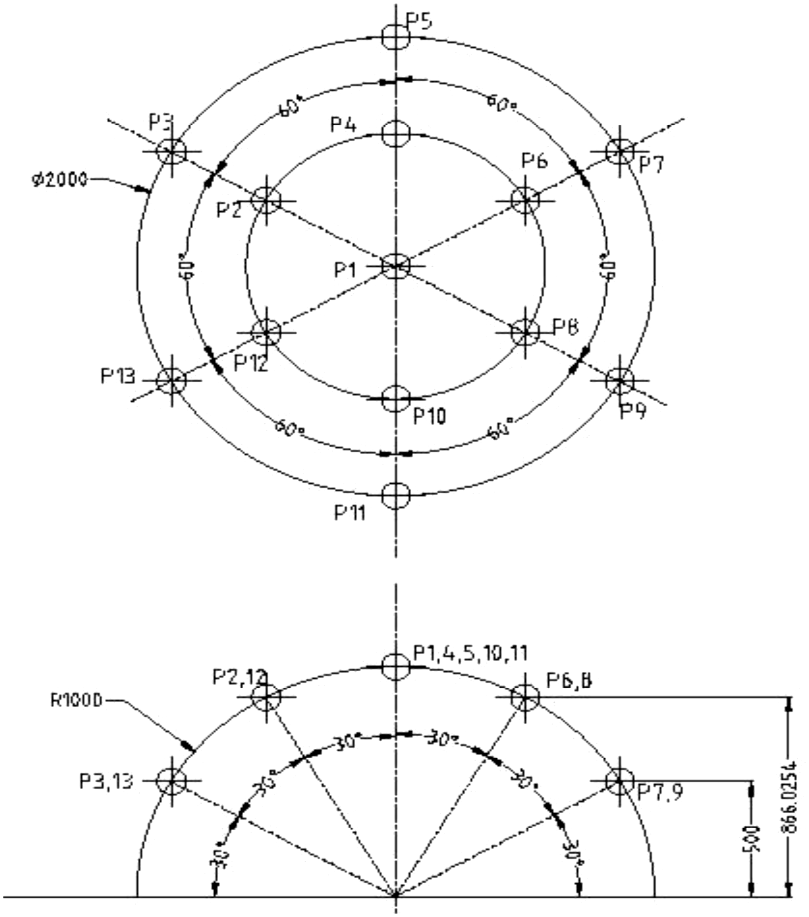
Microphone positions on equal areas on the surface of test hemisphere in free field.
Results and discussion
Acoustic data reduction
Romer 18 discussed the use of dimensionless numbers for representing acoustic test data. Acoustic data reduction has prime importance and implemented to show the collective effect of diameter and thickness on SPL of synthetic jet.
SPL of synthetic jet is dependent on orifice diameter, orifice height, excitation frequency, and voltage. Experimental data have been represented in the form of dimensionless group viz. acoustic Reynolds number and thickness to the diameter ratio. The group 


L = characteristic dimension = orifice diameter = d
ρ = air density = 1.165
μ = dynamic viscosity of air = 1.866×
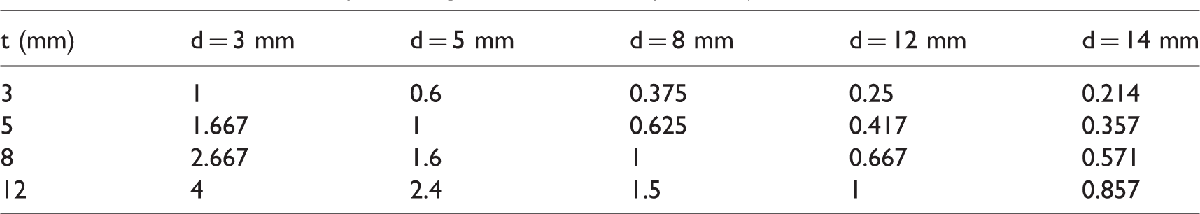
Thickness to the diameter ratio is another dimensionless parameter useful to present effect of variation of thickness and diameter on SPL of synthetic jet. Indirectly, a particular group of t/d ratios indicates an orifice diameter under investigation as shown in Table 3.
Various t/d ratios for presenting acoustic data of synthetic jet.
SPL of synthetic jet for d = 3 mm
Frequency range of 100–700 Hz has been selected because the maximum average suction and ejection velocity is observed in the frequency range of 250–300 Hz, average ejection velocity starts dropping down from 400 to 500 Hz, the ratio of average ejection to the suction velocity decreases monotonically to unity at higher frequencies for all orifice diameters under investigation as shown in Figure 10.16
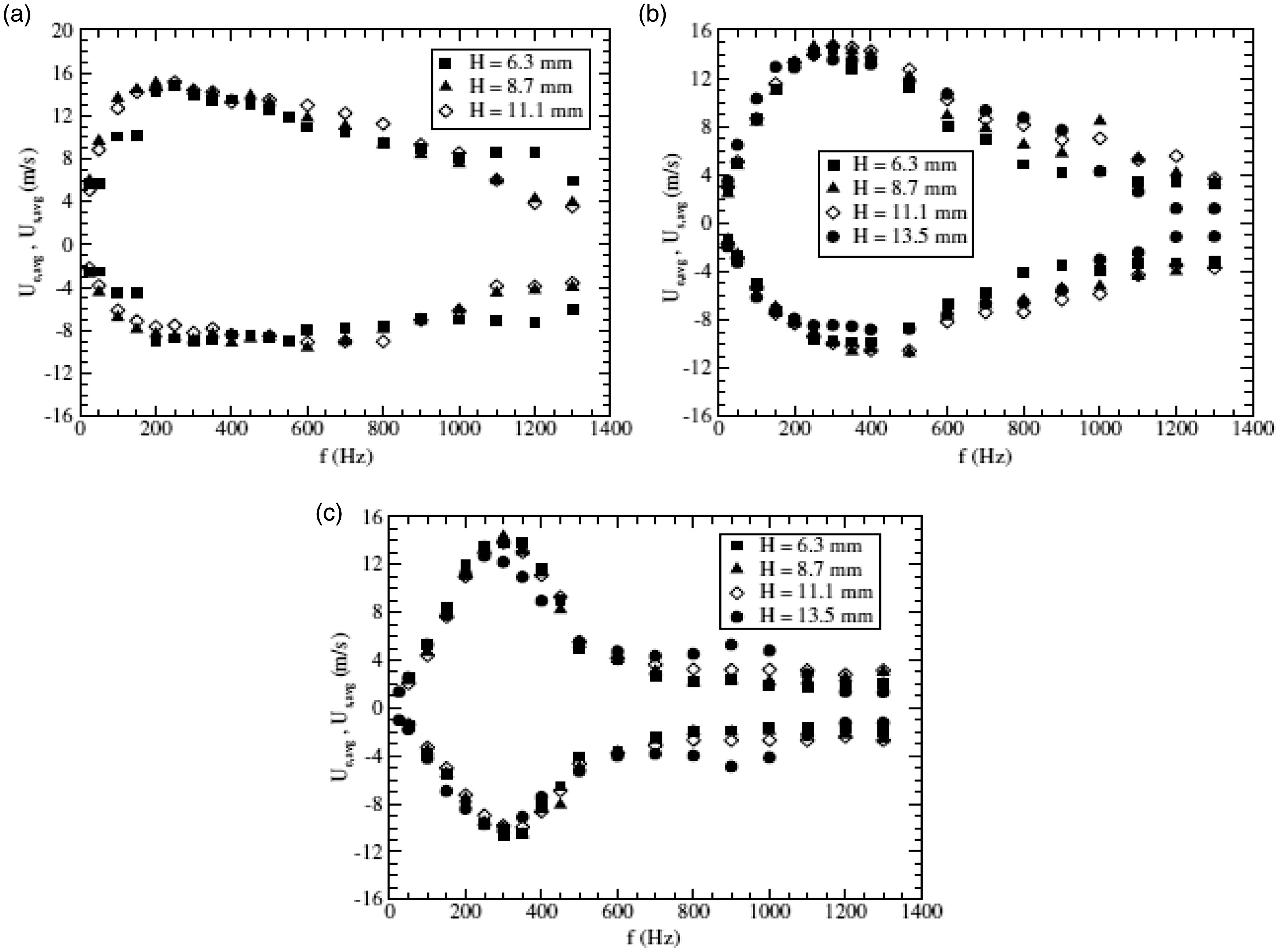
Variation of average ejection and suction velocities of synthetic jet with excitation frequency (a) 3 mm, (b) 5 mm, (c) 8 mm. 16
Moreover, increase in SPL is found after 700 Hz. Deliberately, 100–700 Hz frequency range has been decided because of decreasing average velocity and increasing SPL after this frequency. Some common points emerge out for loudspeaker (electric transducer) and all orifice diameters viz. 3, 5, 8, 12, 14 mm of orifice heights viz. 3, 5, 8, 12 mm operated at intended voltages viz. 2, 4, 6, 8 V.
1. For t=d=3 mm, 2. Since loudspeaker has a paper cone, dips and peaks are observed at certain frequencies because of its softness and more prone to split vibrations as shown in Figures 11 to 14 and Figures 17 to 20.
Hu et al. 19 discussed and evaluated the effect of important elements viz. air in the narrow space between circumference of voice coil and magnetic circuit, Young’s modulus, density of cone and edge, etc. on acoustic characteristics of cone loudspeaker. They have discussed vibration analysis of cone, sound pressure frequency response, and most importantly split vibrations at mid and high frequencies. Damping effect of air viscosity reduces the accuracy of estimating the SPL.
Split vibration:
As the material of paper cone is soft, it is more prone to split vibrations, i.e. the motion of voice coil is not transmitted equally to the entire cone at certain frequencies.
Individuality of loudspeaker:
The shape and material properties of cone are responsible for generating split vibrations in axisymmetric and nonaxisymmetric modes which exert significant influence on loudspeaker’s vibro-acoustic characteristics.
Phase decomposition of loudspeaker:
Klippel 20 found that certain parts of cone of loudspeaker have phases different than the others and leads to interference. The displacement of vibrating surface is decomposed into in-phase, antiphase, and quadrature components with each of them contributing differently to the SPL at different frequencies. In-phase, antiphase, and quadrature components add, subtract, and do not contribute to the SPL, respectively. Therefore, peaks and dips are observed at certain frequencies.
Physical reason:
It is well known that sound absorbing materials cannot provide enough absorption in the low-frequency range because acoustic wavelengths are longer than the dimensions of damping materials. 21 But, it is worthwhile to note that the present concern is not about sound absorption through the acoustic material but about the amplitude decay along the transition path which is air. Moreover, for the same size speakers the air dispersion at longer distance (larger wavelength) will consume more power. So, it is obvious that low frequency consumes more power for same distance travel. It has less transit velocity or more transit time.
Psychological reason:
Increase in SPL (LAeq) with frequency is because of increase in audibility (human perception to the sound) with frequency as it is being A-weighted SPL. Broner 22 stated that sensitivity of human hearing gradually decreases with decrease in the frequency. This is observed in the current experiment of synthetic jet as shown in Figures 11 to 14 and Figures 17 to 20.
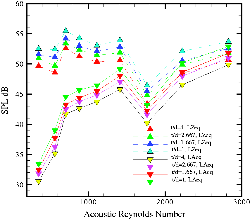
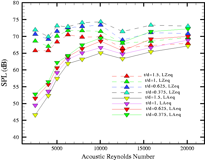
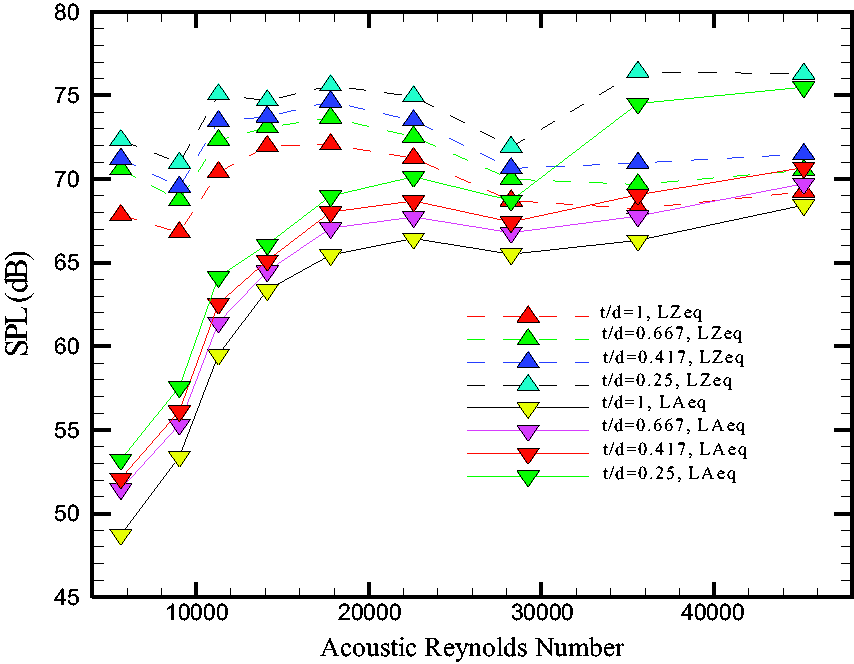
SPL versus acoustic Reynolds number for d = 3 mm at 2 V excitation voltage. SPL: sound pressure level.
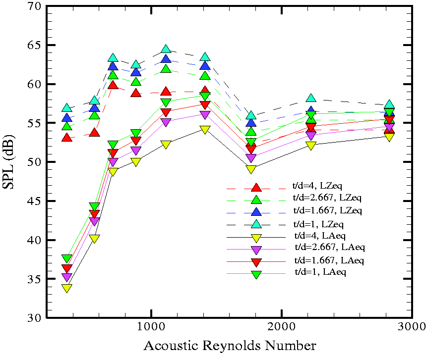
SPL versus acoustic Reynolds number for d = 3 mm at 4 V excitation voltage. SPL: sound pressure level.
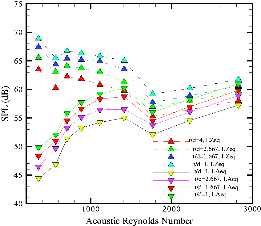
SPL versus acoustic Reynolds number for d = 3 mm at 6 V excitation voltage. SPL: sound pressure level.
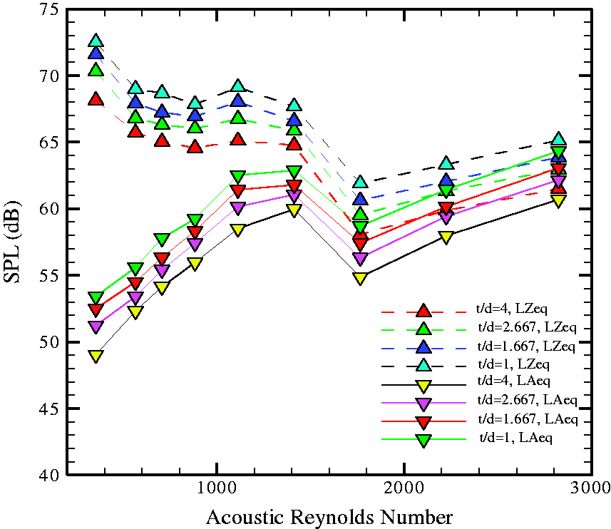
SPL versus acoustic Reynolds number for d = 3 mm at 8 V excitation voltage. SPL: sound pressure level.
3. Drop in SPL and synthetic jet velocity is observed at 500 Hz for 2 in. loudspeaker and all orifice diameters of all heights operated at 2, 4, 6, and 8 V excitation voltages as shown in Figures 11 to 14 and Figures 17 to 20.
4. As the test is conducted with a 2 in. diameter transducer and the source is a standard signal generator the comments are as follows:
i. The tone generator used has an output impedance of 10,000 Ω. 23
ii. The connected load impedance is 8 Ω.
iii. Due to this there is an impedance mismatch which has affected the performance of transducer at higher frequencies.
iv. An acoustic loudspeaker is actually an electroacoustic transducer which converts electrical signal into sound. It commonly consists of diaphragm (cone) with a dust cap, rigid basket (frame/chassis), flexible suspension (spider and surround), voice coil, and permanent magnet. As shown in Figure 16 a gap is established between two poles of a permanent magnet. Central post (pole piece) is the one pole (say N) and the outside of the gap being another (say S) which leads to a generation of permanent magnetic field.
A voice coil is oriented axially inside a circular gap of two poles of a permanent magnet. Suspension system consists of a Spider which connects coil and the diaphragm to the rigid frame. Surround is used to center coil and cone assembly.
An alternating electric current applied to the voice coil (suspended axially in a circular gap between two poles of a permanent magnet) generates a variable magnetic field according to Faraday’s law of electromagnetic induction and its direction is according to Lenz’s law as shown in Figure 15. When such alternating magnetic field generated by voice coil interacts with the permanent magnetic field; leads to generation of mechanical force which causes back and forth motion of the voice coil and diaphragm.
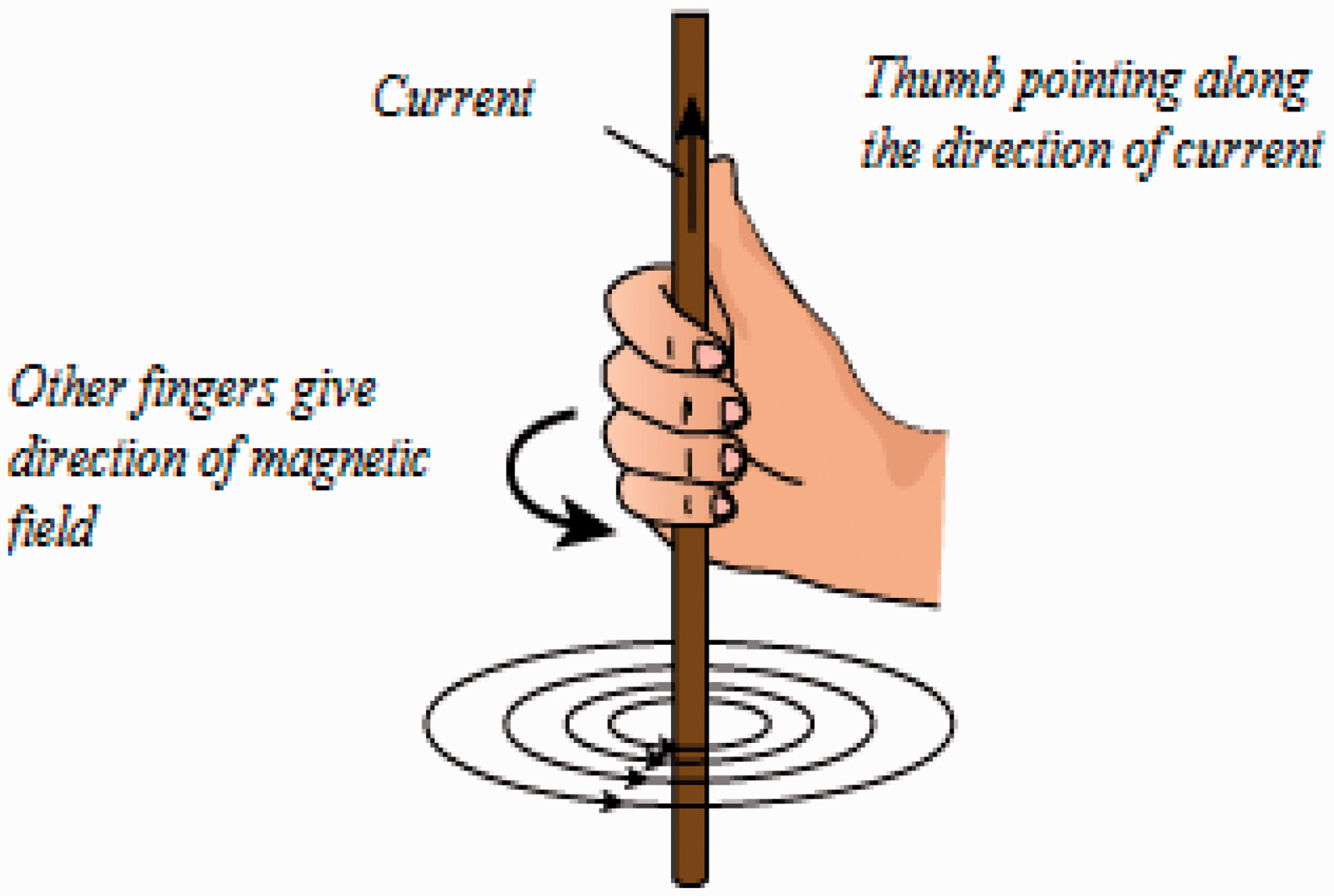
Lenz’s law.
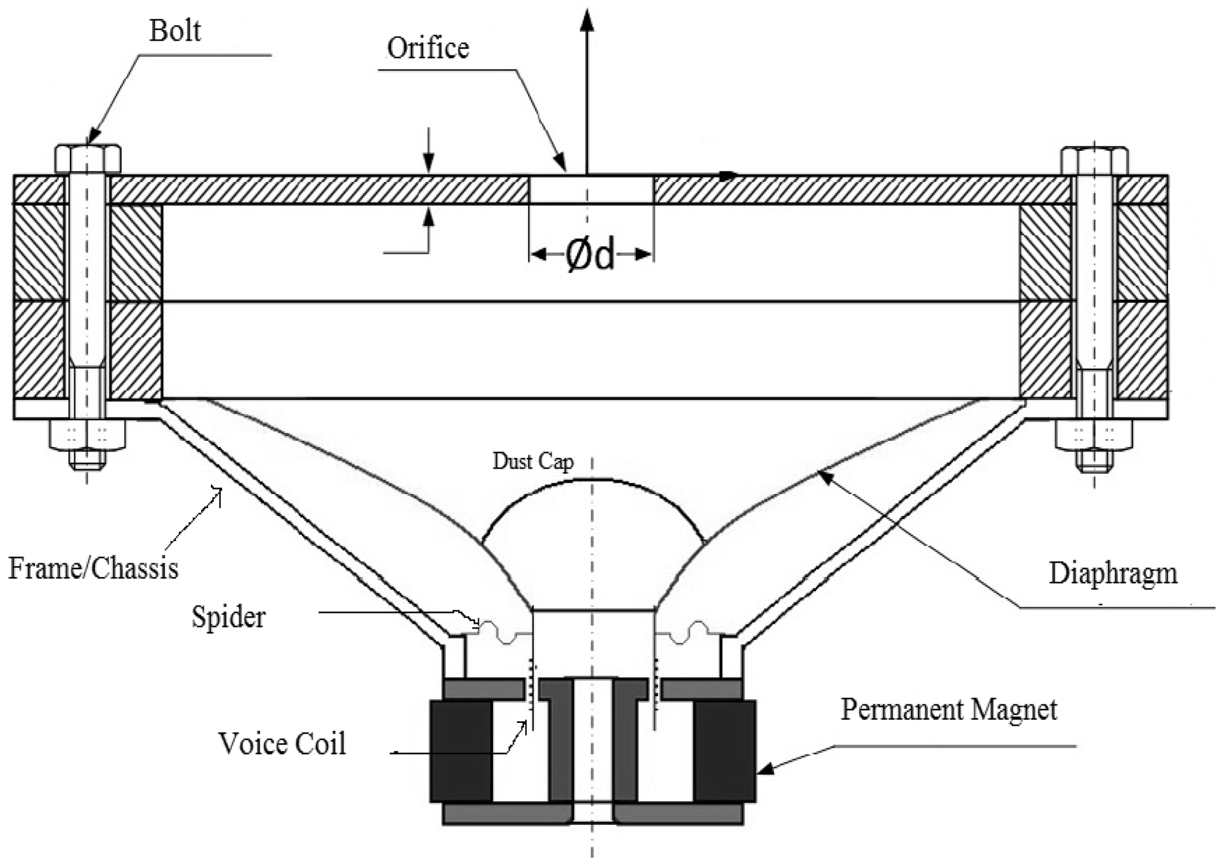
Cut section of electric transducer. 2
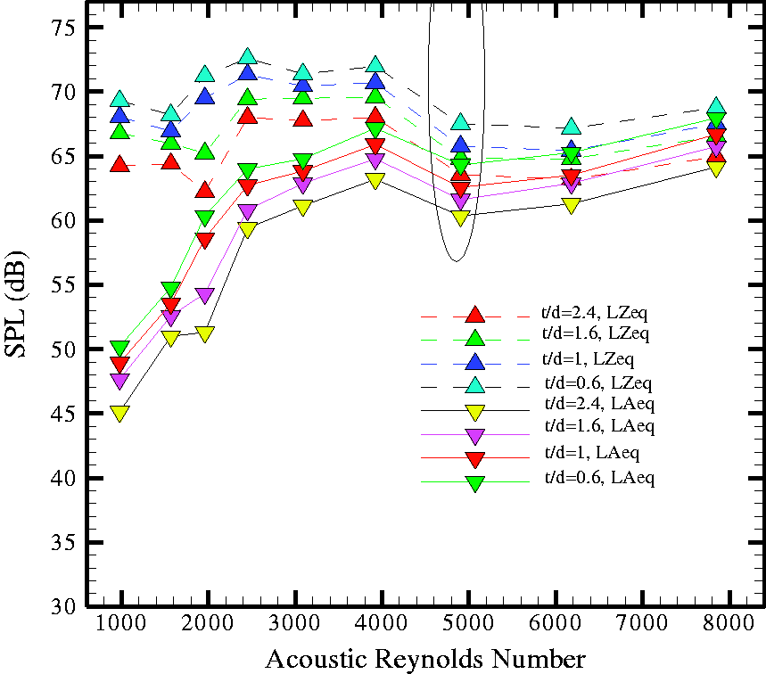
SPL versus acoustic Reynolds number for d = 5 mm at 6 V excitation voltage. SPL: sound pressure level.
SPL versus acoustic Reynolds number for d = 8 mm at 6 V excitation voltage. SPL: sound pressure level.
SPL versus acoustic Reynolds number for d = 12 mm at 6 V excitation voltage. SPL: sound pressure level.

SPL versus acoustic Reynolds number for d = 14 mm at 6 V excitation voltage. SPL: sound pressure level.
Impedance mismatch in current case is just like a short circuit for the source and induces higher current in the voice coil of transducer more than its current-carrying capacity. It will lead to abrupt drop in jet velocity and increase in SPL due to distortion as shown in Figures 10 and 11. For the present experiment the frequency range is quite low. Loudspeaker will not burst due to induction of higher current because low frequency consumes more power for same distance travel but shows heating problem. At higher frequencies as they consume less power there are greater chances of more heating and bursting of synthetic jet loudspeaker.
5. i. Decrease in SPL with increase in orifice height is obvious because less hemispherical spreading of sound wave with increase in orifice height. It leads to more loss of sound energy due to multiple reflections in orifice cavity. ii. True spherical divergence implies no reflecting surfaces at all.
15
iii. Three decibel SPL difference corresponds to double or half of signal power. As such then sound power level of synthetic jet with 3 mm plate thickness is found to double as that with 12 mm thickness for frequency range of 100–700 Hz.
Conclusion
Synthetic jet has potential engineering applications viz. study of cooling patterns of synthetic jet is imperative to increase energy efficiency and reduction of heat load for building and structures. For achievement of few °C reductions in ambient temperature in buildings using jets, we can save ample of kW h energy consumption of air-conditioning system. It leads to less emission of carbon effluents and greenhouse gases responsible for global warming. Loudspeaker (electric transducer) is of different types viz. woofer, squawker, and tweeter depending on the range of frequency it generates. It is well known as Mandra Saptak, Madhya Saptak, and Tar Saptak in the Indian classical music. Woofer generates frequency up to 300 Hz. The range of frequency for squawker and tweeter is 300 Hz–4.5 kHz and 4.5 kHz–20 kHz, respectively. Tweeter-small diameter transducer and Woofer-large diameter transducer are formidable combinations in generating highest sound. In this experiment, a small diameter (2 in.) transducer is operated at woofer frequency range to generate synthetic jet flow hence less noise generation is therefore obvious. This highlights the effective design of synthetic jet but still investigated for noise generation in an acoustic test chamber to confer to the limitations set by the international standards. Spectrum analysis of synthetic jet clearly indicates that the measurements are affected by impedance mismatch. As our main aim was to generate synthetic jet flow, the solution to this problem is not addressed in the current paper in particular. Indeed, it can be solved by using audio amplifier of 8 Ω output impedance for the said transducer or a transducer of 10,000 Ω for the said amplifier. Moreover, this paper attracts additional research to operate synthetic jet for low or high impedance audio amplifiers without mismatch.
Footnotes
Declaration of conflicting interests
The author(s) declared no potential conflicts of interest with respect to the research, authorship, and/or publication of this article.
Funding
The author(s) received no financial support for the research, authorship, and/or publication of this article.