
Abstract
This investigation proposes a series solution method for free and forced vibration analysis of T-shaped plate structure with general elastic supports, arbitrary coupling angles and elastically coupled conditions. The present solution framework can be readily utilized for various boundary or coupling conditions without modifying the solution algorithms or procedures. The general boundary and coupling conditions are considered with artificial spring method and can be easily achieved with assigning the restraining springs with specified values. In the current approach, the displacement functions for in-plane and bending vibration are expressed as a new form of trigonometric series expansion. The sine terms are introduced to eliminate the discontinuity along the boundary edge or coupling edge. Rayleigh–Ritz method is employed to determine the series expansion coefficients, which are treated as the generalized coordinates. Numerous numerical examples are carried out to verify the accuracy and reliability of the present method. The present method can be directly extended to more complicated structures with any number of plates.
Introduction
T-shaped plate structures, which are composed with two rectangular plates joined at edges, are widely used in various engineering structures, such as car bodies, building structures, aerospace structures, ship hulls and marine structures. Determining the vibration of such structures is the critical step for reducing the vibration level in the design phase of developing these kinds of product. Therefore, it is of great importance to investigate the vibration characteristic of T-shaped plate structure with various boundary and coupling conditions.
Because of the wide engineering applications of the plate assemblies, its vibration problems have attracted considerable researcher’s interest and many methods for investigating their dynamical characteristics have been promoted. A theoretical model was developed by Boisson et al. 1 to investigate the vibration energy transmission in finite coupled plates forming L, T, and cross junctions. Farag and Pan 2 presented a theoretical model for the coupling of two plates at an arbitrary angle. They also calculated the vibration response and power flow at the coupling edge and any cross section. Kessissoglou 3 studied the power flow propagation in the low and high frequency for L-shaped plate. Park et al. 4 investigated the longitudinal and in-plane shear waves of thin plates with power flow model. Chen and Sheng 5 employed a mobility power flow method to study the vibration characteristics of L-shaped plate. Liu et al. 6 utilized a wave approach to determine the wave and vibration power propagation in a finite L-shaped Mindlin plate. Lin et al. 7 proposed a closed form solution for the vibration response of an L-shaped plate. A point force or a moment excitation was considered in their study. Chen et al. 8 investigated the vibration characteristics of a box-type built-up structure and energy transmission through the structure with improved Fourier series method (IFSM). In their study, the general coupling and boundary conditions are considered. An energy flow analysis was employed by Ma et al. 9 to investigate the mid-frequency vibration characteristics of built-up plate structures. Wang 10 used the method of reverberation-ray matrix (MRRM) to develop an analytical finite coupled plate model, which was modeled as two Mindlin plates connected at an arbitrary angle. Samet et al. 11 studied the problem of vibration sources identification in coupled thin plates at high frequency range.
From the review of the literature above, it appears that most of the previous studies on the coupled plate are limited to classical boundary conditions and rigid coupling conditions. Only few researches are carried out for vibration analysis of T-shaped plates and plate assemblies with elastic boundary and coupling conditions. Du et al. 12 presented an analytical model for free vibrations of two rectangular plates elastically coupled together at an arbitrary angle based on IFSM. Xu et al. 13 presented Fourier spectral element method for the dynamic analysis of plate structures, which are modeled with any number of arbitrarily oriented rectangular plates. Recently, Jiang et al. 14 presented a spectro-geometric method (SGM) for vibration analysis of built-up structures with elastic boundary conditions. This method is subsequently exploited to the free transverse vibration analysis of truncated conical shells 15 and acoustic cavity. 16 Therefore, the current study can be considered as an extension of the SGM and attempts to provide a general solution method for free and forced vibration analysis of T-shaped plates with general elastic supports, arbitrary coupling angles and elastically coupled conditions. In the current solution framework, the SGM together with the Rayleigh–Ritz method and the artificial spring technique are utilized to derive the theoretical formulation. The arbitrary boundary and coupling conditions of the T-shaped plates are realized by applying the artificial spring boundary and coupling technique. The displacement solutions are invariantly expressed in the new form of series expansions regardless of the boundary conditions. The unknown series expansions coefficients are then obtained with Rayleigh–Ritz procedures. The reliability and accuracy of the proposed solution technique are validated extensively through numerical examples.
Theoretical formulations
Descriptions of the model
Consider T-shaped coupling plate with general elastic boundary supports, arbitrary coupling angles and elastically coupled conditions, as shown in Figure 1. The coupled plate structure are consisted with plate 1 (of length a1 width b, and thickness h1) and plate 2 (of length a2 width b, and thickness h2). The geometry and dimensions are defined in the Cartesian coordinate system (x1, y1, z1) and (x2, y2, z2), respectively. It can be seen from Figure 1 that the model can deal with arbitrary boundary supports, arbitrary connected angles and elastically coupled condition.
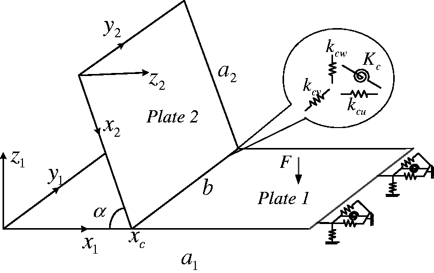
Structure model of the coupling plate with elastic boundary condition.
Three translational springs (kn, kp, kw) and one rotational springs (Kw) are arranged along each edge of the coupled plate structure. Thus, the given boundary conditions can be readily achieved by assigning the translational springs and rotational springs with proper stiffness. For instance, the simply supported boundary condition of the analytical model is approximated by specifying the infinite stiffness (1012) for the translational springs, and zero stiffness for the rotational springs.
It can be seen from Figure 1 that the second plate is connected to plate 1 at the coupling edge x1 = xc. The boundary conditions for all the other “free” edges of plate 2 are free boundary supports. Suppose the x1–y1–z1 is treated as the global coordinate system, the coupling angle α can be defined as the relative position between these two plates. The counter-clockwise is predefined as the positive direction of the coupling angle, which is variable in the range from −π to π.
The compatibility conditions along the plates’ conjunctions are generally described in terms of three-dimensional elastic couplers with both translational and rotational stiffnesses. The three-dimensional elastic coupler is generally described by four distributed springs (Kc, kcw, kcu and kcv) along the coupling common edge, which are utilized to simulate the transverse shearing forces, bending moments, in-plane longitudinal forces and in-plane shearing forces separately. Different coupling conditions can be readily realized by changing the stiffness of the corresponding springs.
Series representations of the displacement functions
In order to construct a unified model, which can be utilized for arbitrary boundary supports and elastic coupling conditions, the admissible displacement functions for plates are unchangeably expressed as an accelerated trigonometric series expansions with SGM.17–22 The displacement function for the transverse vibration of plate i can be described as

The in-plane displacement function in x- and y- direction is separately described as


The use of SGM is to ensure the residual displacement function and its relevant derivatives will not have any potential discontinuities along any edge. Mathematically, the series expansion equation (1) (or equations (2) to (3)) can be able to expand and uniformly converge to any function f(xi, yi)∈C3 (f(xi, yi)∈C1)for ∀ (xi, yi)∈ ([0, ai]⊗[0, b]). Therefore, an exact transverse displacement solution can be obtained as a particular function wi(xi, yi)∈C3 for ∀ (xi, yi)∈ ([0, ai]⊗[0, b]) which satisfies the governing differential equation exactly at every field point and the boundary conditions exactly at every boundary point. The displacement function is constructed sufficiently smooth in this investigation, the weak solution determined using Rayleigh–Ritz method is mathematically equivalent to the strong solution (exact solution). In order to model complex built-up structures, the weak solution is utilized in this study.
Energy description
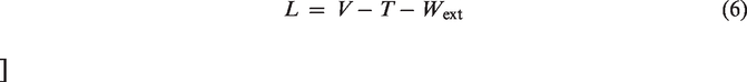
The Lagrangian’s function for the coupled plate system can be generally expressed as
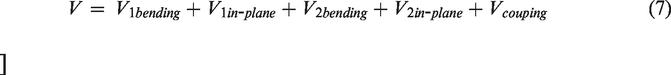

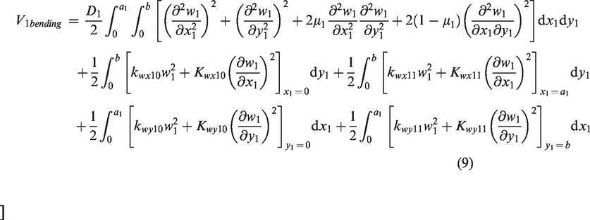
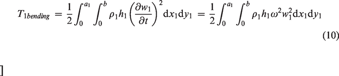
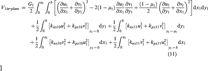
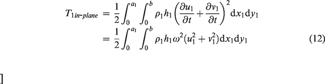
Take plate 1 for example, the potential and kinetic energies can be expressed as
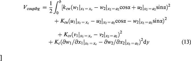
The presence of the three-dimensional elastic coupler can be accounted by the potential energies
The work done by external force can be given as

For a point force, the force function can be expressed as

For simplicity, boundary conditions and coupling conditions are all assumed to be uniform along each edge. But the present method can also be easily extended to the most general boundary and coupling conditions with non-uniform stiffness (varying with the spatial coordinates continuously, discontinuously or discretely). For the non-uniform cases, the stiffnesses in equations (9), (11), and (13) can be expressed as a function of the spatial coordinates.
Solution scheme
Substituting equations (7) to (15) into equation (6) and minimizing the Lagrangian with respect to all the unknown series expansion coefficients, with R as the unknown series coefficients and L as the Lagrangian, the Lagrange equation for the whole system can be obtained as

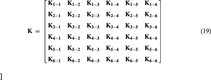
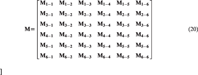
Make a differential calculation in equation (16), a group of linear equations can be derived in the matrix form
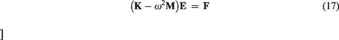
The unknown coefficients in the displacement expressions can be expressed in the vector form as
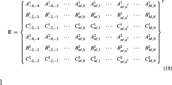
In equation (17),

For the analysis of free vibration characteristics, the load vector
For a given excitation frequency ω, the response vector

To overcome the numerical instability and singularity encountered at modal resonances, the damping of the structure is introduced in the form of complex Young’s modulus.

After the series expansion coefficient vector

Numerical examples and discussion
In this section, a systematic comparison between the current solutions and theoretical results published by other researchers or finite element analysis (FEA) results is carried out to validate the excellent accuracy, reliability and feasibility of the SGM. The discussion is arranged as: Firstly, the convergence of the SGM solution is checked. In addition, influence of the stiffness of boundary spring components is studied. Secondly, the free vibration of the T-shaped plate structure with general boundary condition, arbitrary coupling angles and elastically coupled condition is examined. Finally, the forced vibration of the T-shaped plate structure with general boundary condition, arbitrary coupling angles and elastically coupled condition is also studied.
Free vibration analysis of T-shaped plates
Several examples with different coupling configurations (see Figure 2) will be considered in this section. The geometric parameters are taken as: a1 = 1.5 m, a2 = 1.0 m, b = 1 m, h1 = h2 = h = 0.005 m. The material properties for both plates are given as: E = 7.1 × 10¹⁰ N/m2, ρ = 2700 kg/m3 and mu = 0.3.
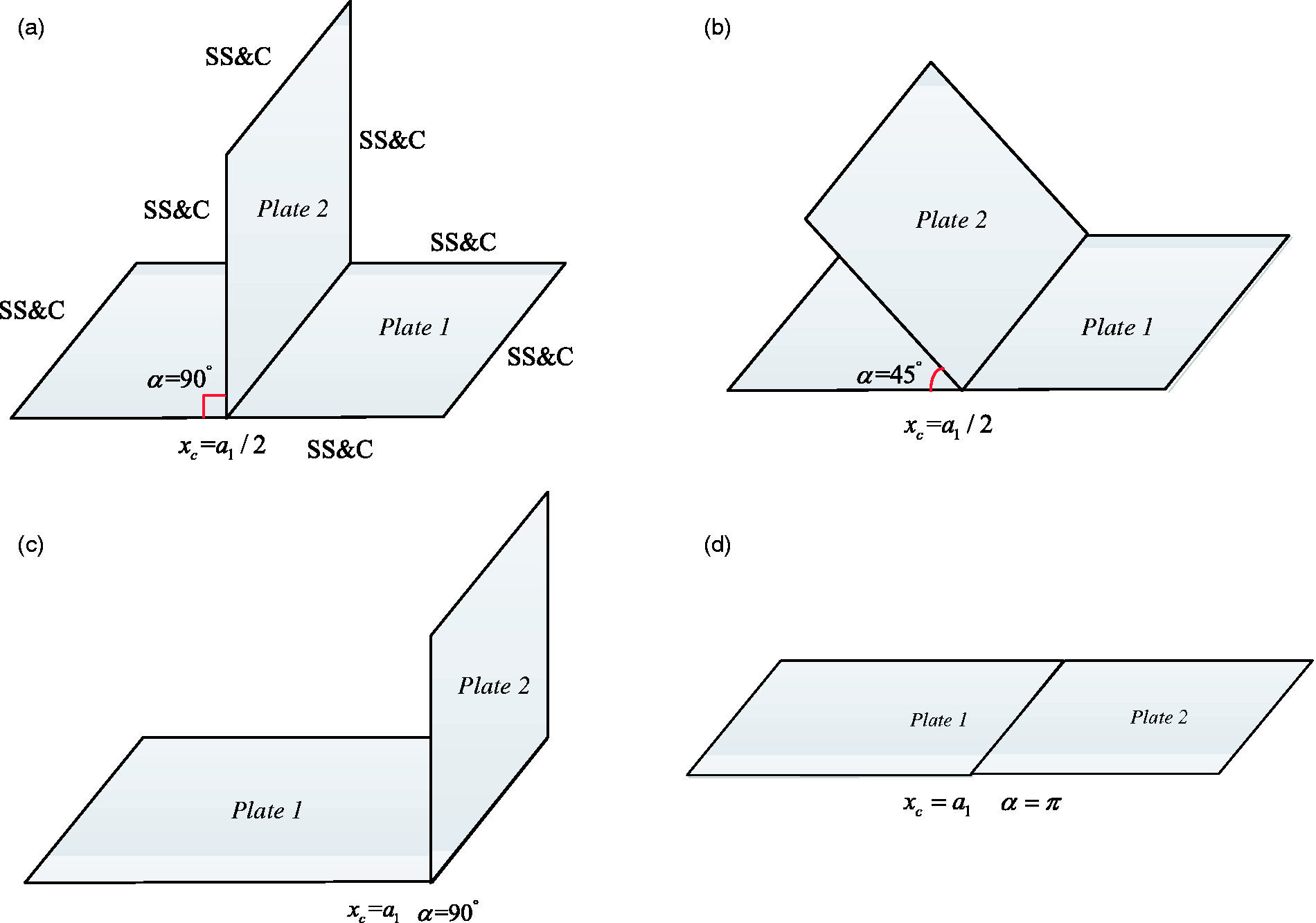
Four coupling configurations with different angles at the structural junction: SS-simply supported for bending component, C- clamped for in-plane component.
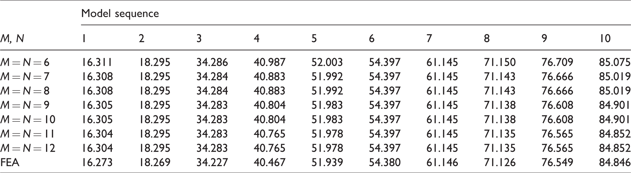
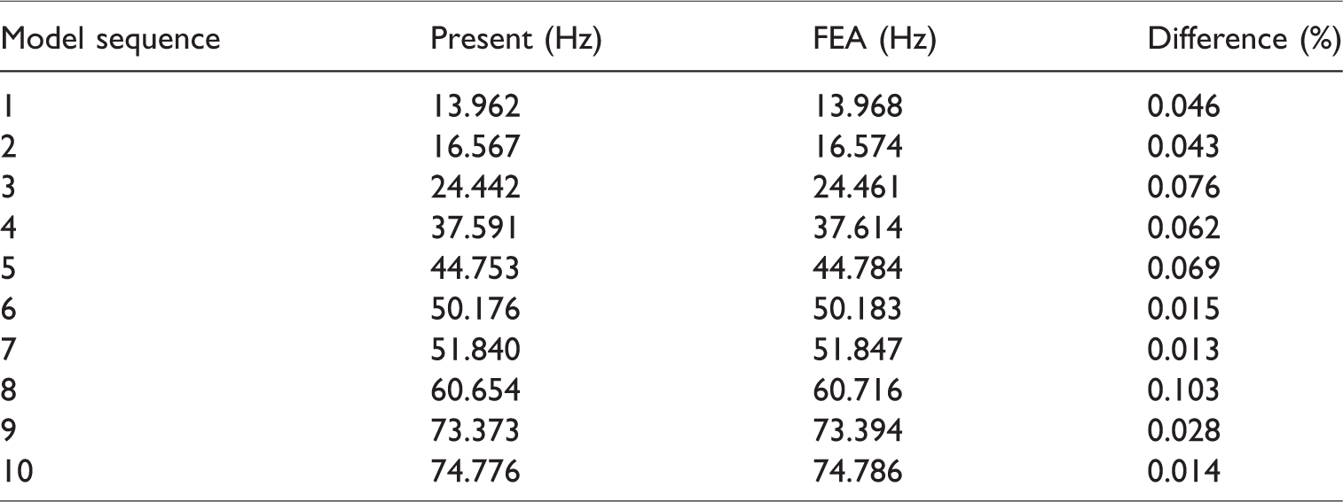
As the first example, T-shaped plate structure (α = π/2 and xc = a1/2) as shown in Figure 2(a) is taken as the research object. The simply supported (or clamped) boundary conditions are specified for bending (or in-plane) vibration displacements on plate 2 along the free edges (x2 = 0, y2 = 0 and y2 = b). The boundary conditions for plate 1 are kept the same with plate 2. The stiffness values of the three-dimensional elastic coupler are given as: Kc = 105 Nm/rad, kcw = 104 N/m, kcu = 104 N/m and kcv = 104 N/m. These stiffness values are close to the nominal bending rigidity of the plate, Eh3/12(1−mu2) = 104. The elastic supports or coupling conditions tend to play an important role on the vibration characteristic of the plate(s). The first 10 natural frequency parameters of the coupled system are listed in Table 1 for different truncation schemes, M = N = 6,7,8,9,10,11,12. The FEA results calculated with ABAQUS model are also given there for comparisons. In the FEA model, the element sizes are uniformly specified as 0.01 m
Natural frequencies for an T-shaped plate structure with the coupling springs: Kc = 105 Nm/rad, kcw = 104 N/m, kcu = 104 N/m and kcv = 104 N/m (Hz).
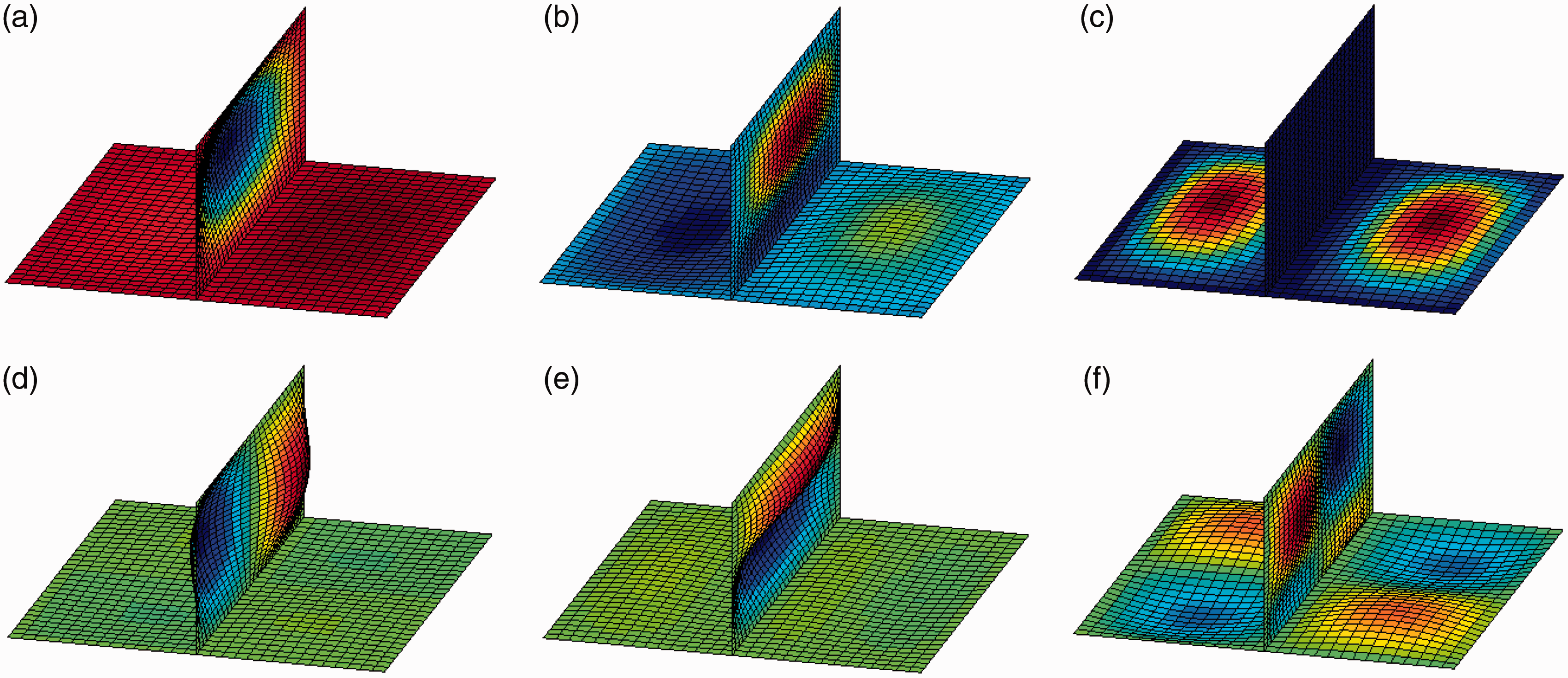
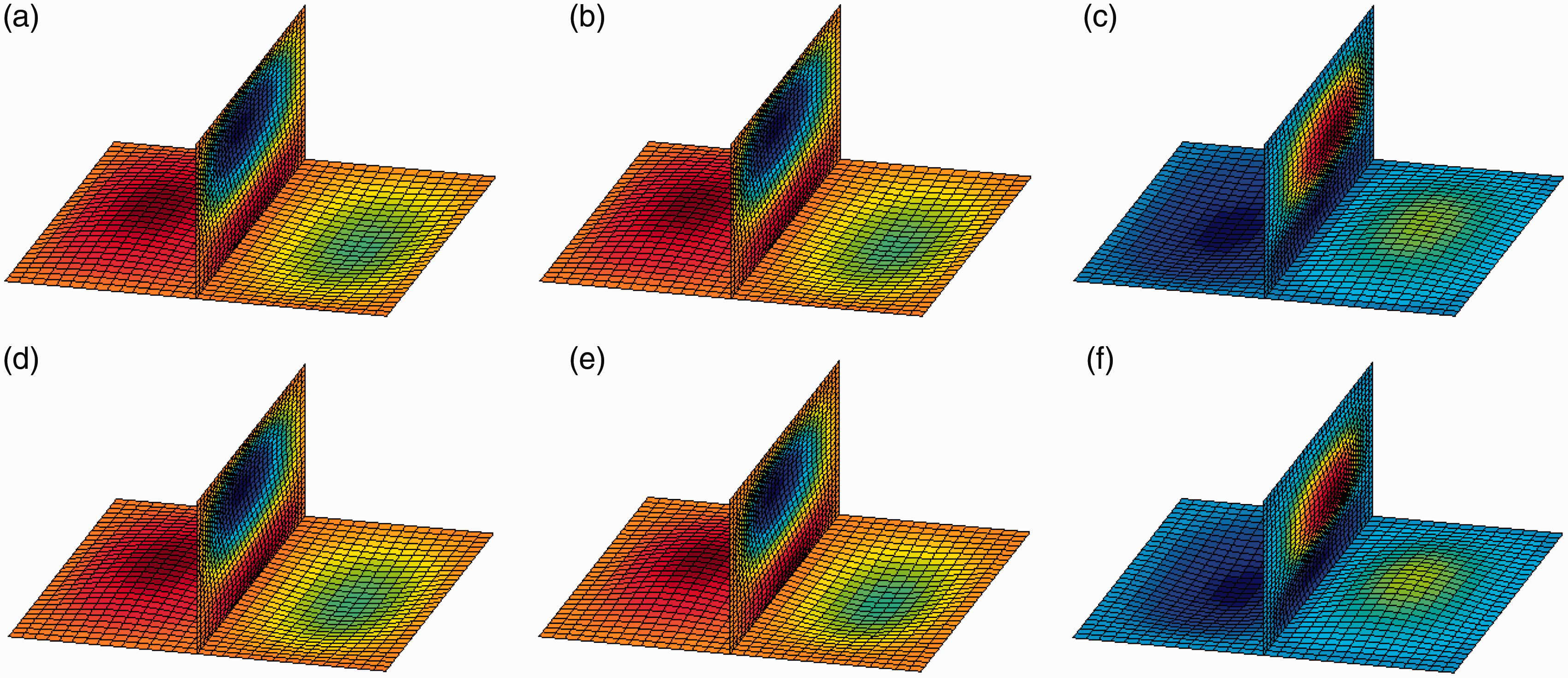
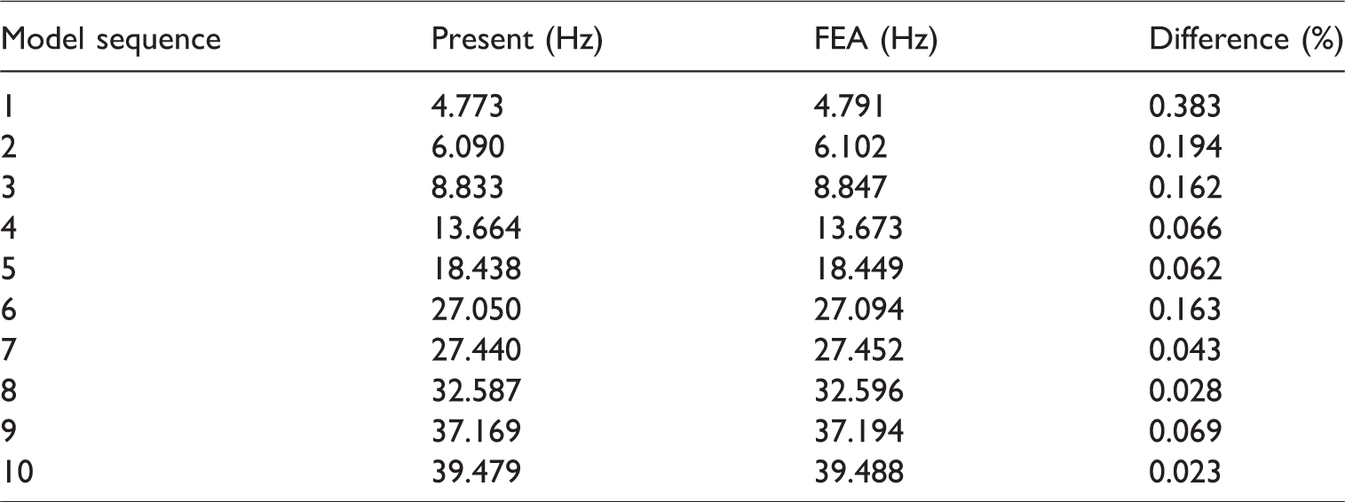
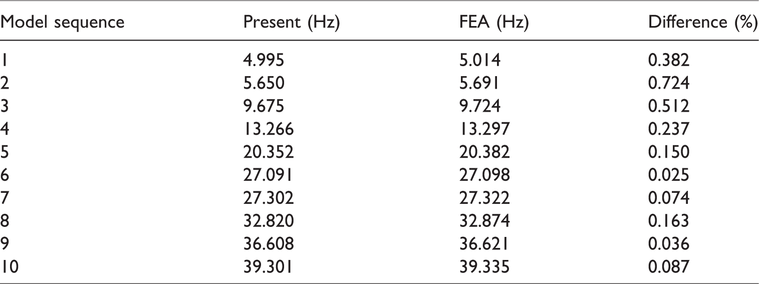
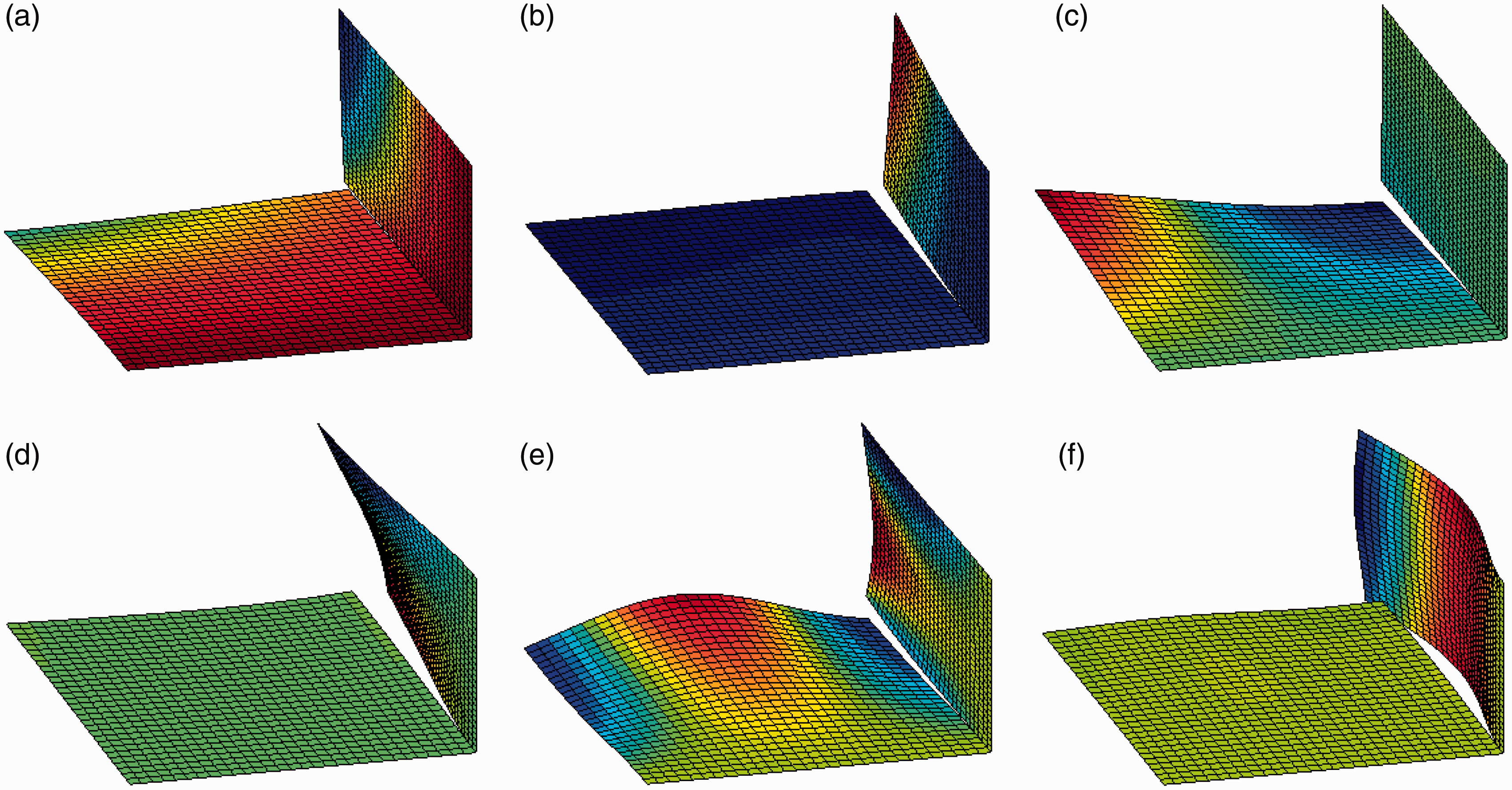
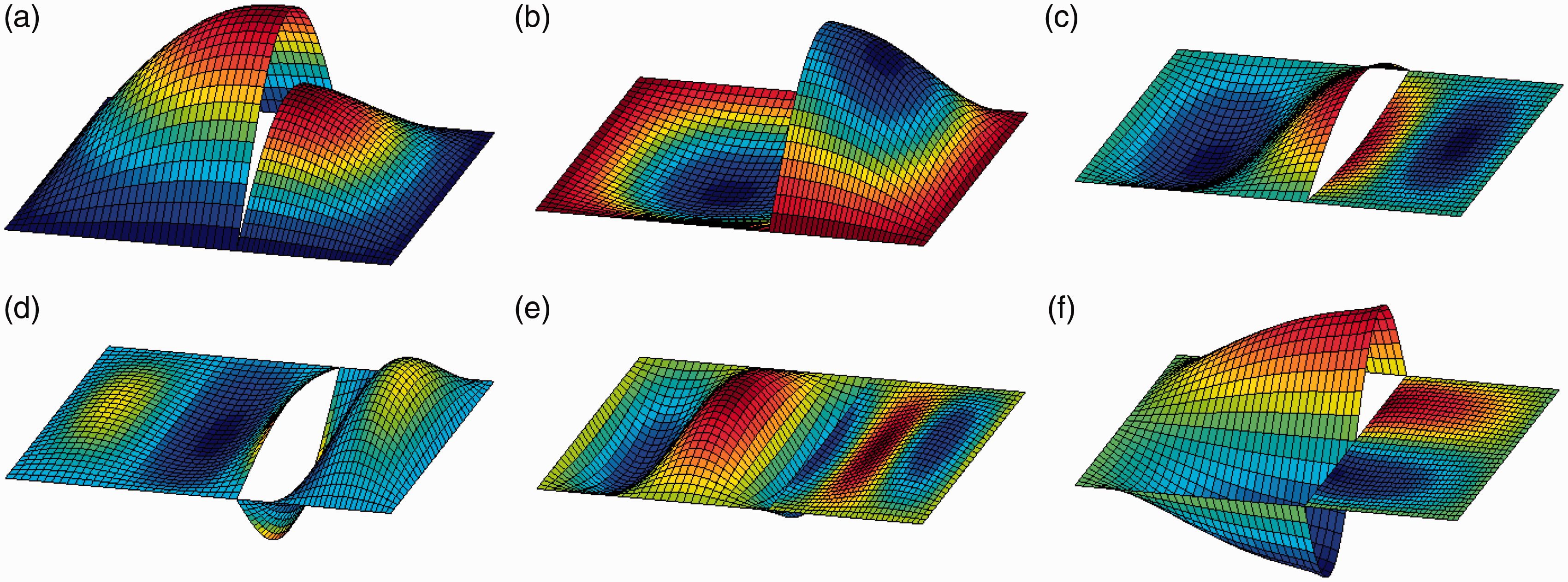
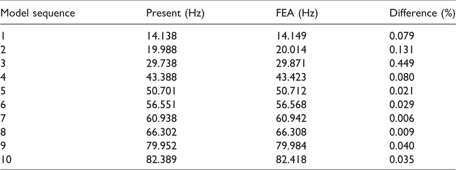
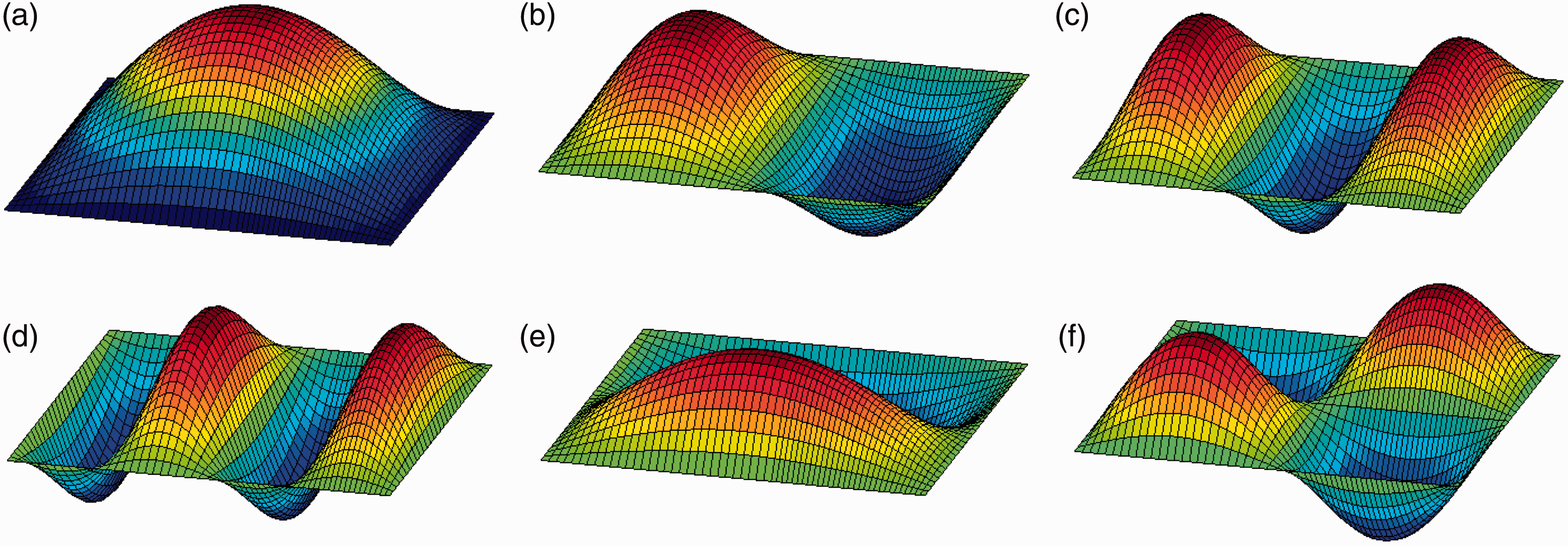
The corresponding mode shapes can be readily calculated by substituting the series coefficients into the displacement expressions, equations (1) to (3). Plotted in Figure 3 are the first six modes for the T-shaped plate structure. It can be seen that due to the elastic coupling, the displacements are no longer continuous across the junction. Now, consider these two plates are rigidly connected together. The condition of rigid connection can be easily simulated by setting the stiffness for elastic coupler to be infinitely large. The corresponding natural frequencies are given in Table 2 together with the FEA results. It can be seen that current results agree well with those obtained from FEA. The first six mode shapes are plotted in Figure 4. Compared with the results plotted in Figure 3, the results for rigid coupling conditions do not have the displacement gaps at the junction. Meanwhile, the mode shape activities can also cover the entire plate structure.
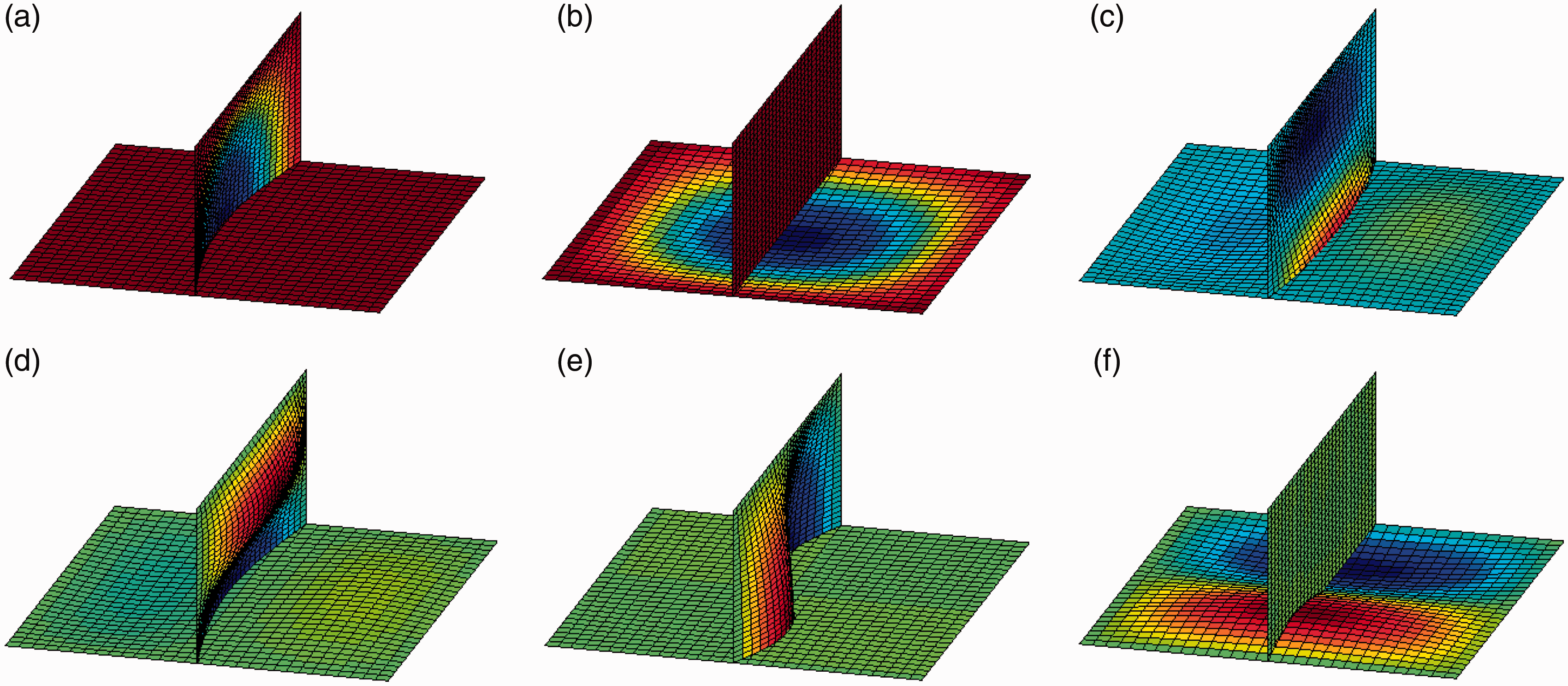
The first six mode shapes for an elastically coupled T-shaped plate structure (xc = a1/2, Kc = 105 Nm/rad, kcw = 104 N/m, kcu = 104 N/m and kcv = 104 N/m.).: (a) 1st mode shape, (b) 2nd mode shape, (c) 3rd mode shape, (d) 4th mode shape, (e) 5th mode shape, (f) 6th mode shape
Natural frequencies for two rectangular plates rigidly coupled in an T-shaped configuration.
The first six mode shapes for the rigidly coupled T-shaped plate structure (xc = a1/2).: (a) 1st mode shape, (b) 2nd mode shape, (c) 3rd mode shape, (d) 4th mode shape, (e) 5th mode shape, (f) 6th mode shape
As mentioned earlier, all the general boundary conditions and elastically coupled condition can be conveniently viewed as special cases when stiffness for boundary springs and coupling springs become zero and/or infinitely large. Thus, the effects of the stiffness of boundary springs (kw, Kw, kn, kp) and coupling springs (Kc, kcw, kcu, kcv) on the modal characteristics of the T-shaped plate structure should be investigated. Since there are various possible varying conditions of boundary springs and coupling springs, for simplicity, just a type springs stiffnesses is considered to be changed, while the other type springs stiffnesses are all set as infinitely large numbers. The non-dimensional stiffness
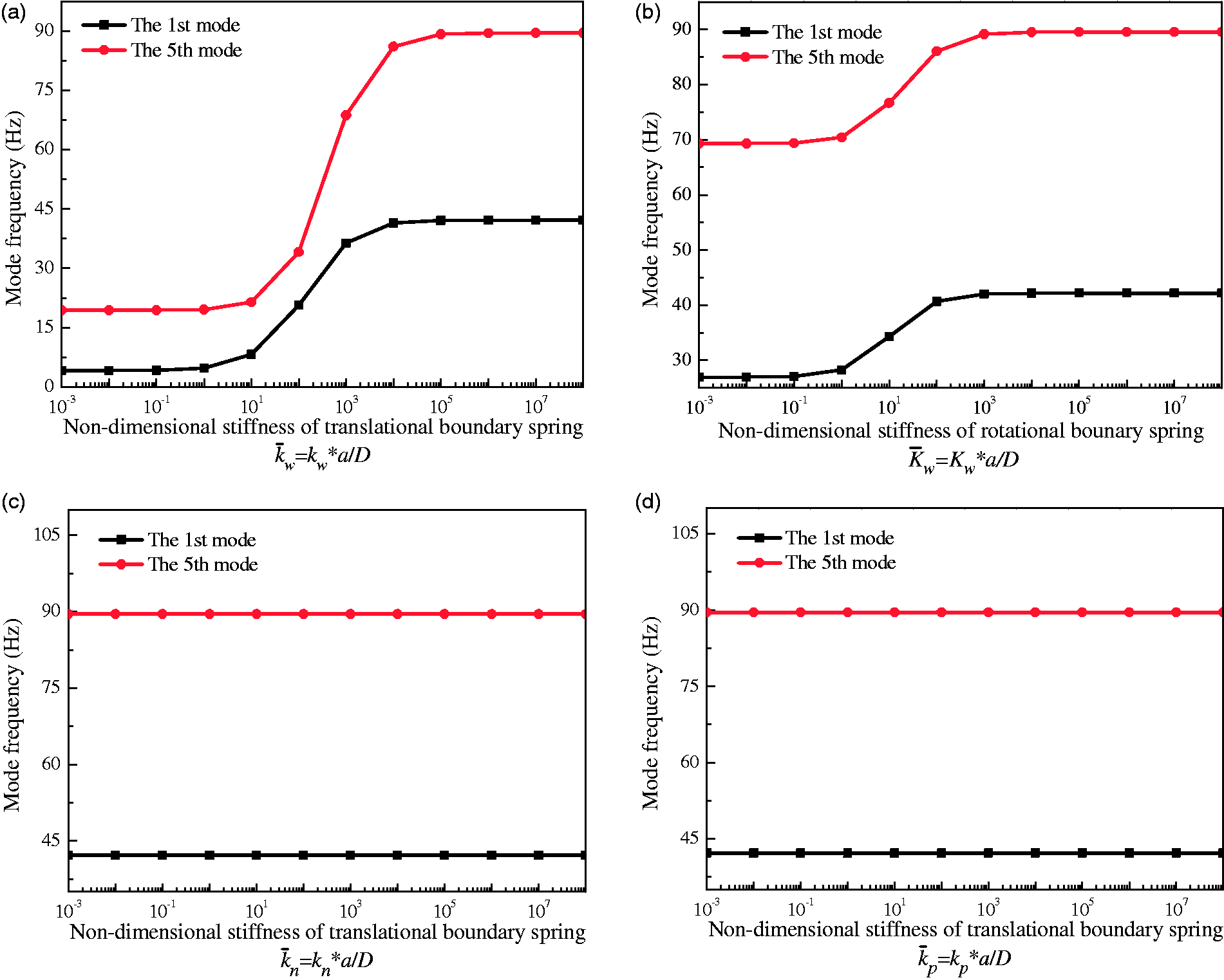
The effect of boundary spring stiffness on the natural frequencies: (a) kw, (b) Kw, (c) kn, (d) kp.
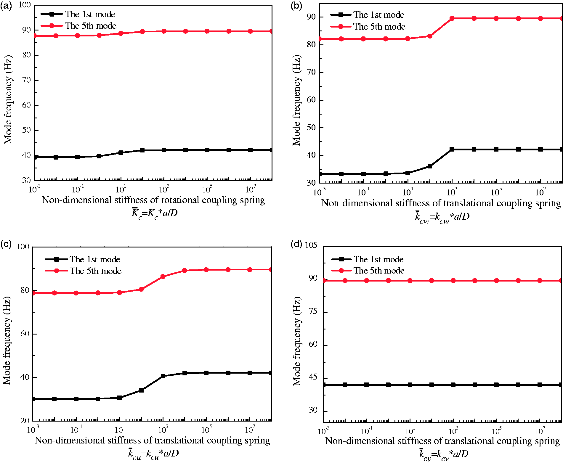
The effect of coupling spring stiffness on the natural frequencies (a) Kc, (b) kcw, (c) kcu, (d) kcv.
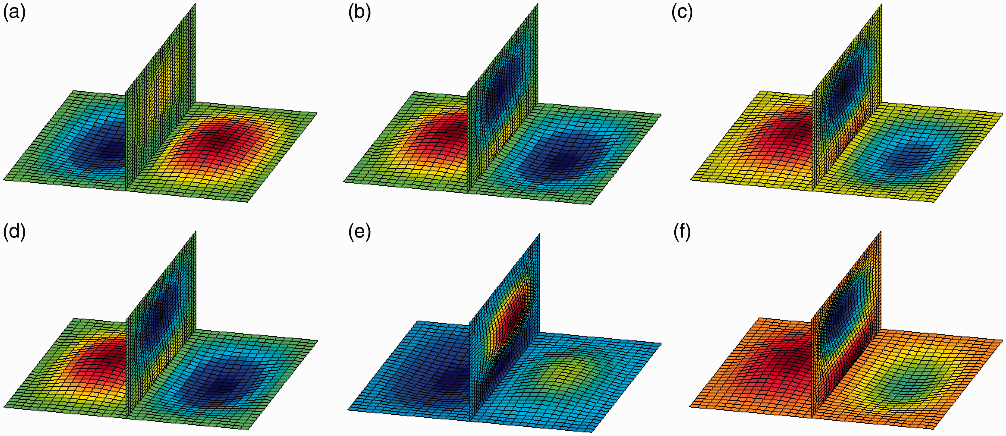
In order to further investigate the influence of the boundary spring and coupling spring on the coupled plates system, the effect on the first 8 modes for T-shaped plate structure with different boundary rotational and coupling rotational stiffness coefficients are shown in Tables 3 and 4. Similar influence trend of the boundary and coupling conditions can be found for the other structural modes. In fact, this boundary and coupling stiffness effect behavior can be also understood by observing the evolution of spatial distribution pattern of the coupled structural mode, as given in Figures 7 and 8 for the second mode cases. From Tables 3 and 4 and Figures 7 and 8, it is clearly shown that how the transfer from separate modes into a joined mode occurs within the coupling stiffness sensitive zone.
Evolution of the second mode shape of the T-shaped plate with the variation of boundary conditions: (a)
Evolution of the second mode shape of the T-shaped plate with the variation of coupling conditions:(a)
The first eighth modal frequencies of the T-shaped plate with various non-dimensional rotational boundary spring stiffness
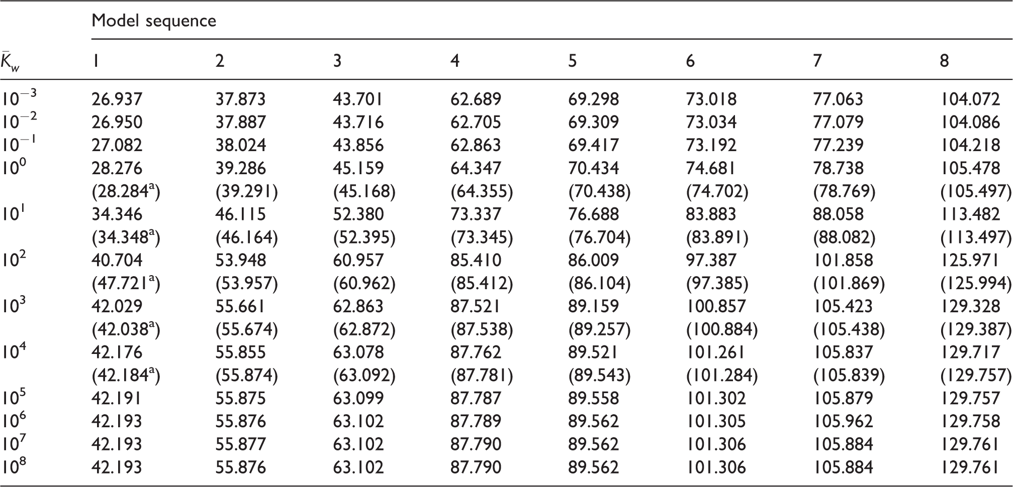
aResults in parentheses are taken from FEA.
The first eighth modal frequencies of the T-shaped plate with various non-dimensional rotational coupling spring stiffness
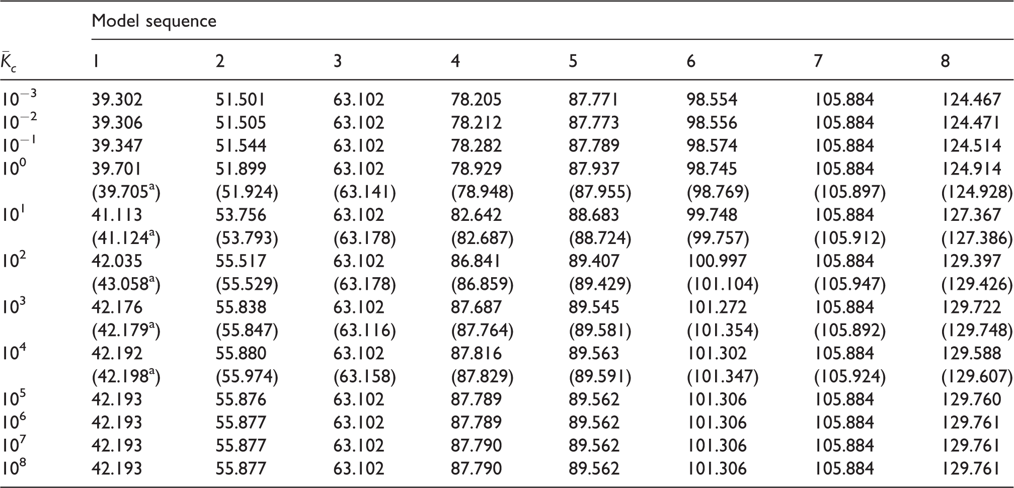
aResults in parentheses are taken from FEA.
Now, change the coupling angle to 45° which corresponds to the second configuration as shown in Figure 2(b). In addition, the boundary conditions are modified; that is, both the flexural and in-plane displacements on each plate are now clamped at y = b, and all other edges are completely free. In Table 5, the first 10 natural frequencies are presented for the elastic coupling condition: Kc = 107 Nm/rad, kcw = 104 N/m, kcu = 104 N/m and kcv = 105 N/m. The first six modes are shown in Figure 9. They clearly exhibit a global characteristic as compared with those modes given in Figure 4 for the T-shaped plate structure case. When the coupling angle is different from 90°, the flexural vibrations on both plates will be directly coupled together through the transverse spring kcw. In the next example, we will change the coupling location xc = a1/2 to xc = a1, as in shown Figure 2(c). Figure 2(b) and (c) has the same boundary conditions. The first 10 natural frequencies are given in Table 6 for the elastic coupling condition: Kc = 105 Nm/rad, kcw = 104 N/m, kcu = 104 N/m and kcv = 103 N/m and α = 90°, the FEA results are also listed in Table 6 as a reference. The first six modes are shown in Figure 10. It can be clearly seen that the comparison is extremely good, which implies that the current analysis model is able to make correct predictions for the L-shaped plate structure. Based on these analysis, Table 7 given the first 6 natural frequencies under different coupling location (xc = 0 m, 0.53 m, 0.83 m) and coupling angle (α = 30°, 60°, 120°), the FEA results calculated using ABAQUS are also presented as a reference. Again, good agreement can be observed. Through Table 7, it is found that the current method is also suitable to solve the T-shaped plate structure with the arbitrary coupling angles (α) and coupling location (xc).
The mode shapes for two plates elastically coupled at the angle of 45-degree with the following coupling springs: Kc = 107 Nm/rad, kcu = 104 N/m, kcv = 104 N/m and kcw = 105 N/m.: (a) 1st mode shape, (b) 2nd mode shape, (c) 3rd mode shape, (d) 4th mode shape, (e) 5th mode shape, (f) 6th mode shape
Natural frequencies for two plates coupled at 45° with the coupling springs: Kc = 107 Nm/rad, kcw = 104 N/m, kcu = 104 N/m and kcv = 105 N/m.
Natural frequencies for L-type plates (α = 90°) with the coupling springs: Kc = 105 Nm/rad, kcw = 104 N/m, kcu = 104 N/m and kcv = 103 N/m.
The first six mode shapes for an elastically coupled L-shaped plate structure: Kc = 105 Nm/rad, kcu = 104 N/m, kcv = 104 N/m and kcw = 103 N/m.: (a) 1st mode shape, (b) 2nd mode shape, (c) 3rd mode shape, (d) 4th mode shape, (e) 5th mode shape, (f) 6th mode shape
Natural frequencies for two plates under different coupling angle and coupling location (Hz).
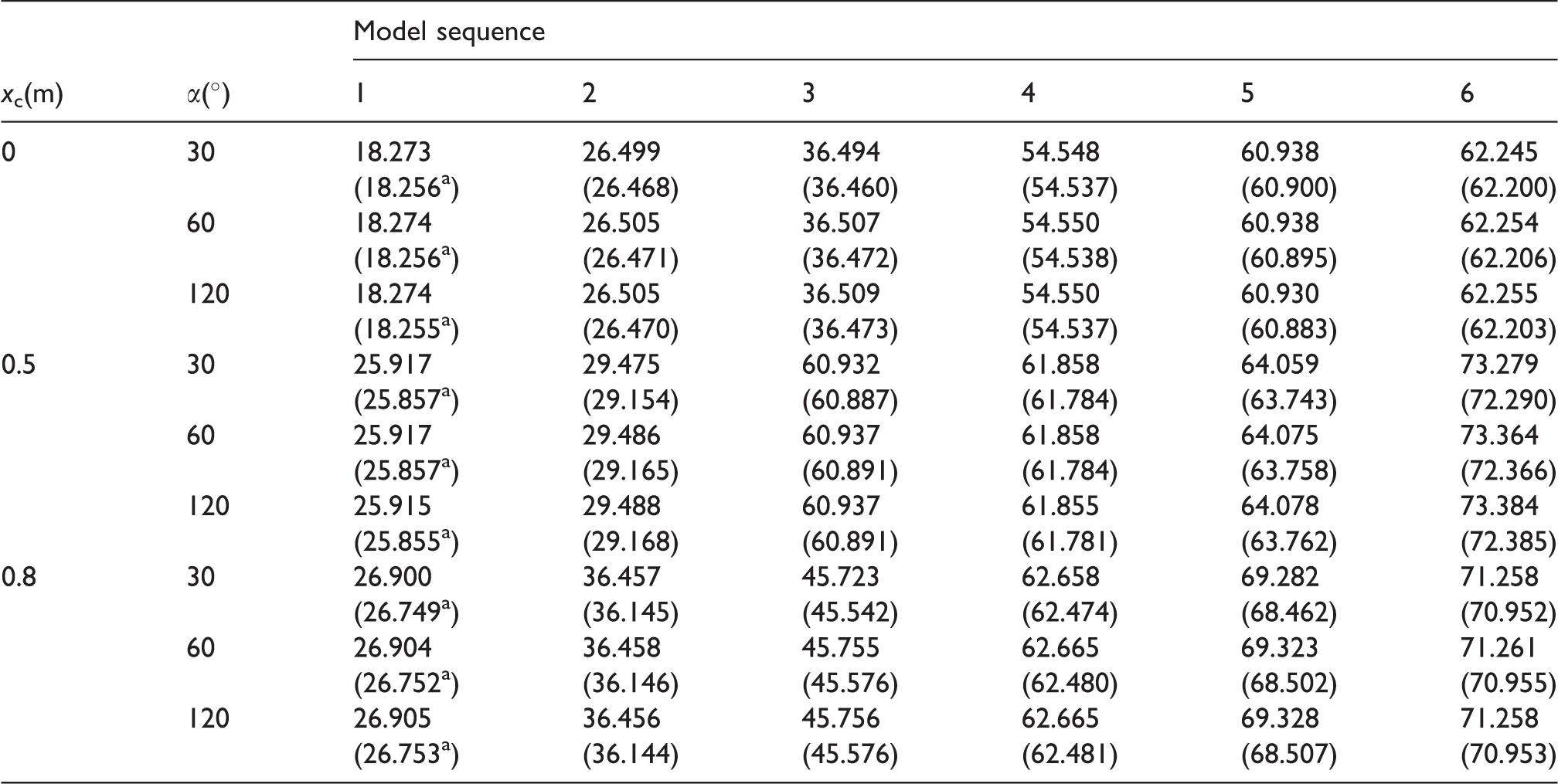
aResults in parentheses are taken from FEA.
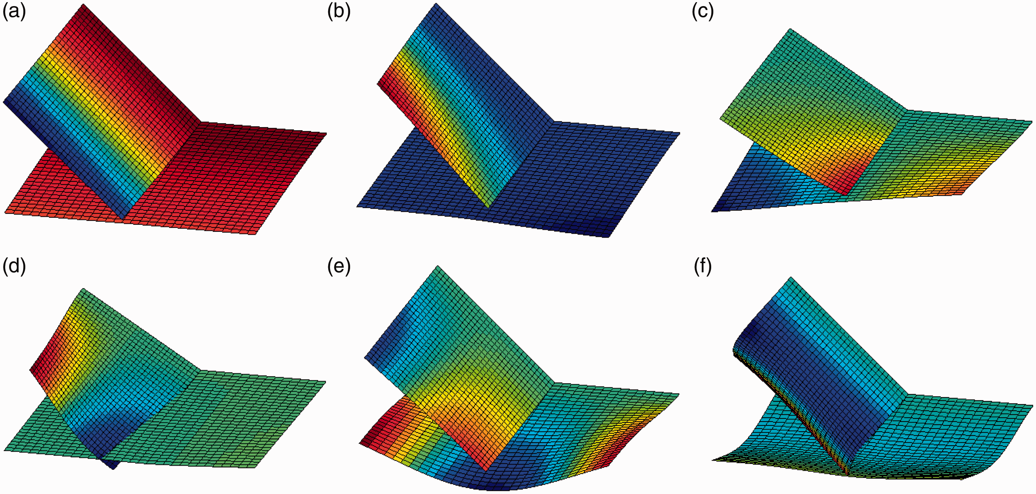
Lastly, a flat configuration as illustrated in Figure 2(d) will be considered for both elastic and rigid coupling conditions. In this example, the boundary conditions will be changed back to the ones as previously specified for the T-shaped plate structure. When the coupling angle is equal to π, the bending and in-plane vibrations will essentially become decoupled, and can be determined separately. For the elastic connection, the coupling springs are taken as Kc = 105 Nm/rad, kcw = 104 N/m, kcu = 104 N/m, and kcv = 103 N/m. In Table 8, the calculated natural frequencies are compared with those calculated from an ABAQUS model. The first six mode shapes are plotted in Figure 11. It is seen that the weak coupling actually allows the plates to move almost independently.
Natural frequencies for the π-angle coupled plate structure with the coupling springs: Kc = 105 Nm/rad, kcw = 104 N/m, kcu = 104 N/m and kcv = 103 N/m (Hz).
The mode shapes for two plates elastically coupled in a flat configuration with the following coupling springs (Kc = 105 Nm/rad, kcu = 104 N/m, kcv = 104 N/m and kcw = 103 N/m).: (a) 1st mode shape, (b) 2nd mode shape, (c) 3rd mode shape, (d) 4th mode shape, (e) 5th mode shape, (f) 6th mode shape
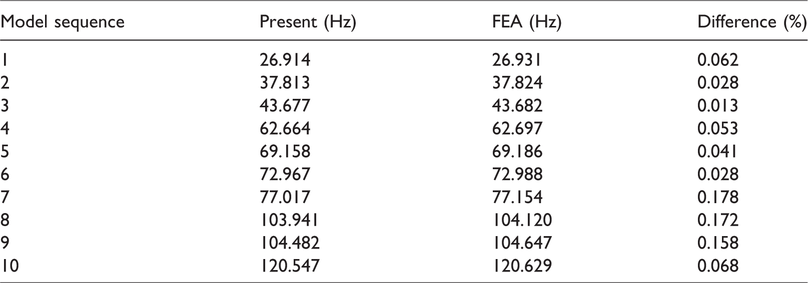
The rigid connection condition is obtained simply by increasing stiffness values of the coupling springs to infinity. In this case, the two plate structure simply degenerates to a single plate, which has a combined length of a1+a2. Thus, the calculated natural frequencies and mode shapes can be directly compared with the analytical results for a single simply supported plate. A comparison of the natural frequencies is made in Table 9. The first six mode shapes are shown in Figure 12. The minor differences for the calculated natural frequencies are believed due to the combination of the numerical truncation of the series expansions and the actual finiteness (instead of infinity) of the stiffness values for the boundary and coupling springs. This example, although it may appear to be trivial, has some very important implications, for instance it says that a continuous plate component can be arbitrarily divided into a number of pieces to avoid non uniformities/irregularities related to geometry or materials.
A comparison of the first 10 natural frequencies for the two plates rigidly coupled in a flat configuration.
The mode shapes for a rigidly coupled plate structure in a π-degree configuration.: (a) 1st mode shape, (b) 2nd mode shape, (c) 3rd mode shape, (d) 4th mode shape, (e) 5th mode shape, (f) 6th mode shape
Forced vibration analysis of T-shaped plates
This section concentrates on the forced vibration problems of T-shaped plates structure with general boundary condition, arbitrary coupling angles and elastically coupled condition are also studied. In this section, the structural parameter and the material parameter are the same as those in ‘Free vibration analysis of T-shaped plates’ section. The model has the same boundary condition and coupling angle as that in Figure 2(a), and the stiffness is rigid coupled connection. The harmonic external lateral exciting force with 1 N amplitude acts on point A (0.6 m, 0.5 m) on plate 1 in the coupled system. The mobility characteristics of point A on plate 1 and point B (0.4 m, 0.5 m) on plate 2 are shown in Figure 13. At the same time, the results obtained with FEA software ABAQUS are also utilized to verify the validity and reliability of the methods and computational models in this study. The element size for the FEM model is 0.01 m × 0.01 m, which can accurately catch the vibration response characteristics of the structural system. It can be seen from Figure 13 that the computational methods of this study can accurately predict the mobility characteristics of the coupling plate structure system. The mobility characteristics change with the frequency, and the frequency value of the resonance peak stays the same as the inherent frequency of the system.
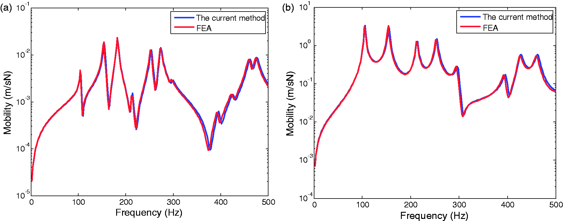
The mobility characteristics of the rigid coupling plate structure system.: (a) point A, (b) point B
When the coupling connecting spring stiffness is changed, the coupling plate structural system will turn into elastic coupling plate structural system. The mobility characteristics for coupled system with elastic coupler (Kc = 103 Nm/rad, kcu = 104 N/m, kcv = 105 N/m and kcw = 106 N/m) are shown in Figure 14. It can be seen that the elastic coupler obviously affects the mobility characteristics of the coupling plate structural system, and the mobility characteristics of the rigidly coupled plate structural system are apparently higher than those with elastic coupler system.
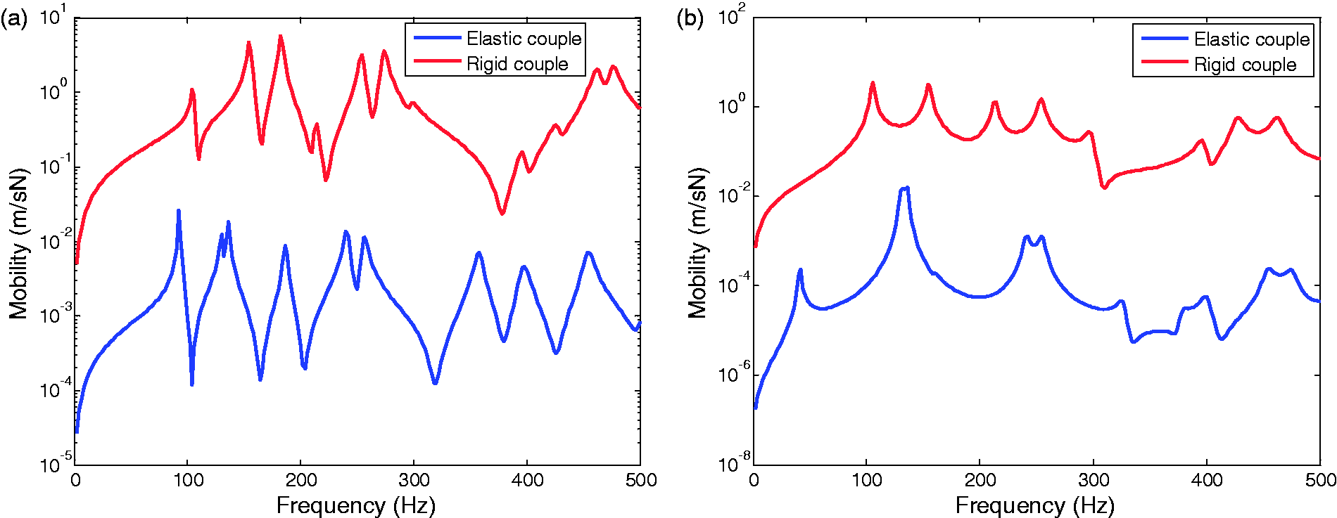
The mobility characteristics of the elastic coupling plate structure system.: (a) point A, (b) point B
Conclusions
A general method is presented for the free and forced vibration analysis of T-shaped plate structure with general elastic supports, arbitrary coupling angles and elastically coupled conditions. Unlike the existing solution framework, each “free” edge for two plates can be elastically restrained by a set of elastic springs with arbitrary stiffness. The bending and in-plane vibration displacement functions for each plate are described as an improved trigonometric series expansion with SGM. These displacement functions can deal with arbitrary boundary conditions and coupling conditions. The unknown series expansion coefficients are treated as the generalized coordinates and determined using the Rayleigh–Ritz procedure.
The accuracy and reliability of the proposed solution method have been illustrated through numerical examples which include various boundary conditions and coupling configurations. From the numerical computation, the present method derived here is a numerically efficient and accurate solution applicable to a wide range of vibration problems of T-shaped plate structure. Since the free and forced vibration analyses of T-shaped plate structure with general elastic supports, arbitrary coupling angles and elastically coupled conditions have not been reported previously, it is believed that the numerical results presented in this paper will be useful to future researchers. In addition, compared to other solving technique such as FEA and other analytical solution, the following advantages may be drawn out: (1)no mesh is used, then there is no need for mesh refinement like the FEA does as the analysis frequency increases; (2) a fast convergence rate is observed, which implies that the efficient calculation can be achieved; (3) the current method does not involve much any modification to the solution algorithm or procedure when the boundary or coupling condition is changed. The current model can also be used to investigate the effect of a boundary or coupling condition on the dynamic behavior of a built-up structure and on the power flows through any junctions and structural components.
Footnotes
Acknowledgments
The authors would like to thank the anonymous reviewers for their very valuable comments.
Declaration of conflicting interests
The author(s) declared no potential conflicts of interest with respect to the research, authorship, and/or publication of this article.
Funding
The author(s) disclosed receipt of the following financial support for the research, authorship, and/or publication of this article: The authors gratefully acknowledge the financial support from the National Natural Science Foundation of China (Grant No. 51505445) and the key subject “Computational Solid Mechanics” of the China Academy of Engineering Physics.