
Abstract
In this paper, the tracking control of periodic oscillations in an underactuated mechanical system is discussed. The proposed scheme is derived from the feedback linearization control technique and adaptive neural networks are used to estimate the unknown dynamics and to compensate uncertainties. The proposed neural network-based controller is applied to the Furuta pendulum, which is a nonlinear and nonminimum phase underactuated mechanical system with two degrees of freedom. The new neural network-based controller is experimentally compared with respect to its model-based version. Results indicated that the proposed neural algorithm performs better than the model-based controller, showing that the real-time adaptation of the neural network weights successfully estimates the unknown dynamics and compensates uncertainties in the experimental platform.
Keywords
Introduction
The study of oscillatory behavior as well as its control in many physical systems has been an active research topic in recent years. For example, Parmananda et al. 1 reported numerical and experimental results indicating successful stabilization of unstable steady states and periodic orbits in an electrochemical system. Semenov et al. 2 investigated the stabilization of the inverted pendulum with vertically oscillating suspension under hysteretic control. In Olm et al., 3 an analysis of digital controllers under time-varying sampling period for the tracking of periodic oscillations was given. More recently, tracking control of a class of nonlinear systems using oscillation was considered in Wang and Guo. 4 Specifically, based on the oscillation functions associated with accessible vibrating components of the system, oscillatory control was designed to track a desired trajectory.
There is a large class of underactuated mechanical systems which arises from problems in robotics and mechatronic systems. The Furuta pendulum is an underactuated electromechanical system of two degrees of freedom (DOF) and has only one actuator. 5 It is an inverted pendulum, which is classified into a nonlinear, nonminimum phase and underactuated system. 6 One of the most important applications of Furuta and inverted pendulums is to test linear and nonlinear control techniques. Some control techniques developed are bang-bang control,5,7 PID control,8,9 energy-based control,10–12 feedforward control,13,14 sliding mode control,15,16 fuzzy logic,17–19 singular perturbation-based control, 20 as well as hybrid control 21 and predictive control. 22 However, we will focus our attention to neural network-based control.23–25
Artificial neural networks are useful to compensate unknown dynamic systems. There are some works where neural networks were used with this objective as Nelson and Kraft 26 where a full-state feedback optimal controller was developed to control an inverted pendulum in the upright position. In Sazonov et al., 27 a hybrid system controller, incorporating a neural network plus an optimal linear controller applied to inverted pendulum in regulation mode was presented. The work in Shaheed 28 introduced an open-loop control strategy with neural networks for vibration suppression in a flexible manipulator system. In Jung and Cho, 29 a decoupled reference compensation technique with neural networks applied to the control of a two DOF inverted pendulum mounted on a x–y table was presented. In Noh et al., 30 the implementation of position control applied to a mobile inverted pendulum using radial basis function neural networks was presented.
On the other hand, feedback linearization is a known control technique used in nonlinear systems.31,32 The basic idea of this technique consists in defining an output function (usually linear in terms of the system state), which is derived r times with respect to time until the control input appears. Thus, the controller can be computed so that the solutions of resulting closed-loop system in terms of the output converge to zero. Depending on the class of the underactuated mechanical system under consideration and the proposed output function, the closed-loop system may be composed of an internal dynamics which must be stable in order to accomplish the control task. 33 The previous literature review shows that only a few works have addressed the problem of tracking control of periodic oscillatory trajectories of the Furuta pendulum.
In this paper, the problem of inducing periodic oscillatory behavior in the Furuta pendulum is addressed by proposing a new adaptive neural network-based controller for the tracking of periodic trajectories. The proposed control algorithm has a structure inspired by a model-based controller, which is designed using the feedback linearization technique with a new output function. The advantage of using adaptive neural networks is that the parameters of the dynamic model are not needed for the design of the control algorithm. The convergence analysis of the output trajectories is shown and conditions for the solutions of the internal dynamics to be bounded are given. An extensive experimental evaluation is performed in a test bed, where the new adaptive neural network controller is compared with respect to its model-based version. The two controllers are tested using two different periodic trajectories, showing that better tracking performance is obtained with new scheme.
Furuta pendulum dynamics and control goal
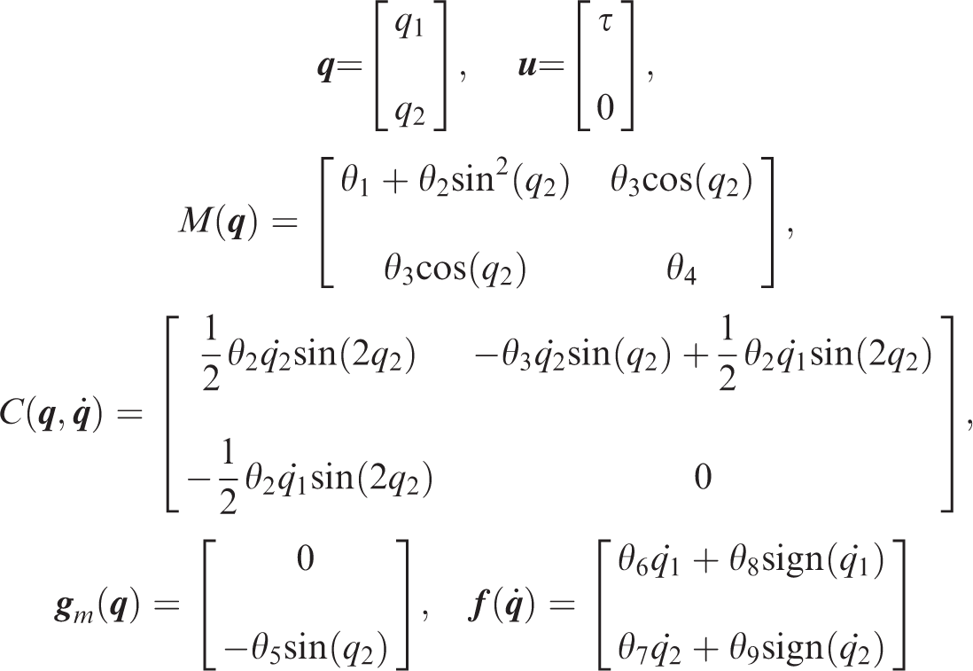
As mentioned before, the Furuta pendulum is an underactuated system of two DOF. Figure 1 shows a description of the joint positions and applied torque. The dynamic model of the Furuta pendulum in Euler–Lagrange form6,34–36 is written as

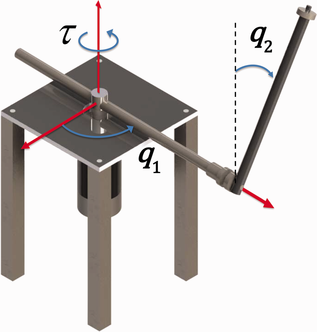
Three-dimensional model of the Furuta pendulum with the relative measurement of the joint positions and applied torque.
It is assumed that the desired trajectory

The motivation of introducing oscillatory behavior in pendulum-like systems has been well explained in Canudas-de-Wit et al. 37 and Shiriaev et al. 38 where the authors established that a pendulum is the simplest model of a walking robot leg and introducing periodic behavior in the closed-loop system for underactuated mechanical systems is an approach to solve the motion control problem in walking robots.
The joint position tracking error vector is defined as

Then, the control problem consists in designing a controller
Adaptive neural network controller
The Furuta pendulum model in equation (1) can be rewritten as


The control goal is to satisfy with only one input τ(t) the tracking of a desired trajectory for the arm position while the pendulum remains regulated at the upward unstable equilibrium. In other words, both the trajectory tracking error e1(t) and the regulation error e2(t) defined in equation (3) must remain bounded in a region around the origin, in spite of the fact that only one actuator is available to control the system. Thus, the designed control action

The time derivative of the output in equation (8) is


A feedback linearization controller is proposed for the cancellation of nonlinearities through a feedback control law, transforming the nonlinear system in equation (9) into an equivalent linear system whose trajectories converge asymptotically to the origin. The proposed control law is given by

where the proportional term ky, with the positive constant k, ensures the asymptotic convergence of the output trajectories; the nonlinear term

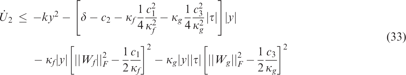
It is possible to show that y(t) converges to zero. A way to prove this claim is computing the time derivative of the following positive definite function


As can be seen, the time derivative of U1 given in equation (15) is a negative definite function, proving that the trajectories of y(t) converge to the origin with exponential rate of convergence as time t goes to infinity.
A smooth function

Then, taking into account the model-based controller in equation (12), the following adaptive neural network controller is proposed


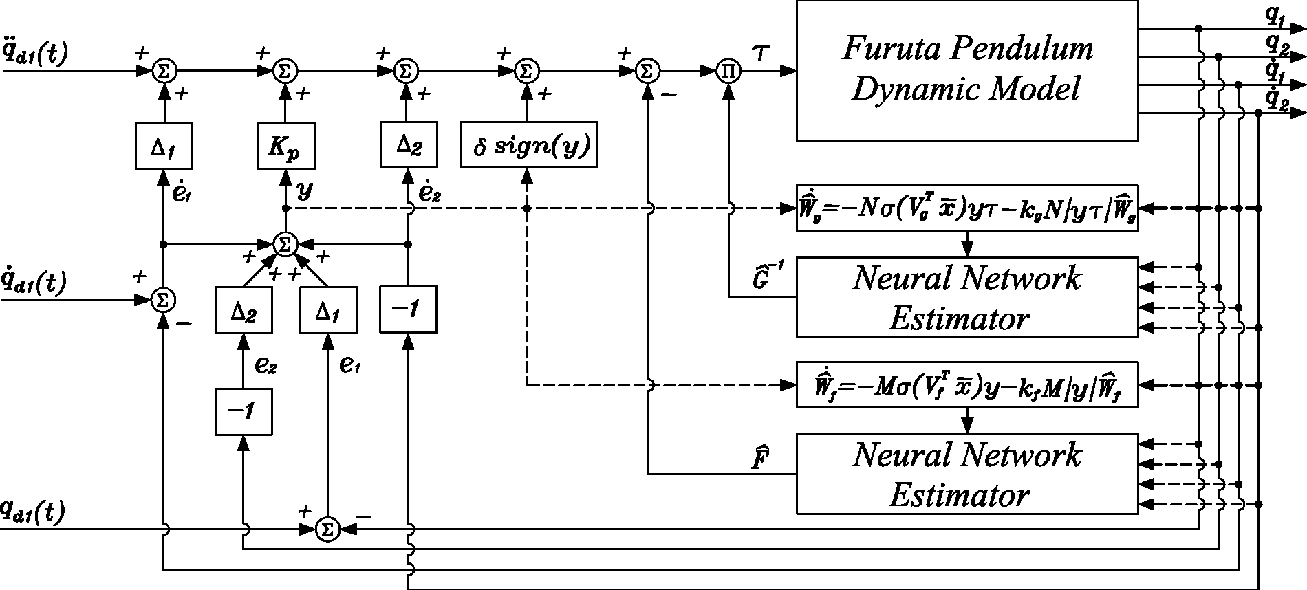
Block diagram implementation of the adaptive neural network controller in equation (17).
The proposed controller in equation (17) has a nonlinear quotient structure with an adaptive neural network function in the numerator and another one in the denominator. Besides, the controller includes linear PD terms in the tracking error
By using the universal function approximation property of the neural networks in equation (16), which implies that


Taking into account that the ideal weights Wf and Wg are constants, equations (19) and (20) can be written in terms of the estimation errors


In order to prove that the solution y(t) coming from closed-loop system in equations (21) to (23) converges to zero as time t increases and the output weight estimation errors


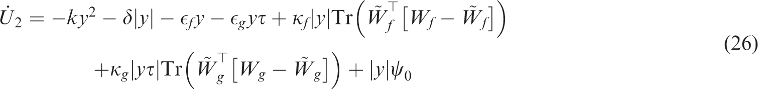


Thus, using the definition in equation (29) and the property in equation (30), the signal ψ0 in equation (28) satisfies

The definition in equation (30), the fact

Since the torque τ(t) in equation (17) is bounded for some compact set of the state space

As
By using the transformation
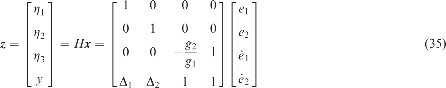
which is invertible, the internal dynamics can be computed as follows
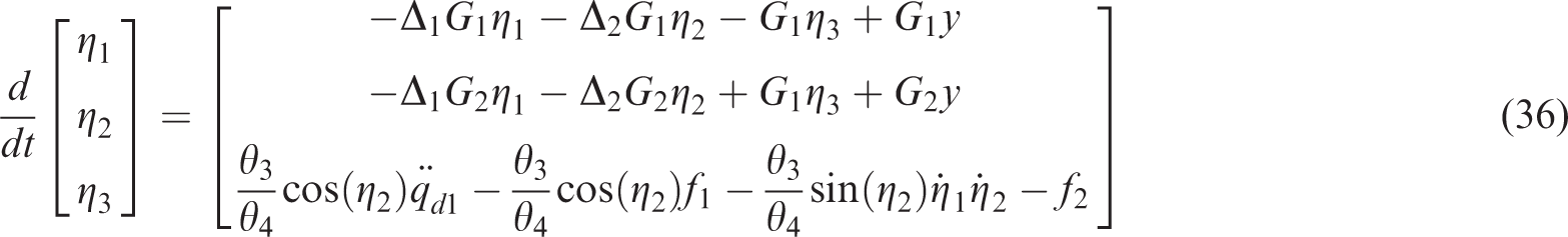
A local analysis of the system (36) showed that necessary and sufficient conditions to ensure the uniformly ultimately boundedness of the trajectories


Experimental results
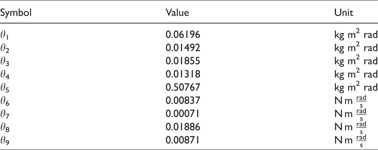
In this section, two controllers are experimentally tested: the model-based feedback linearization controller in equation (12), and the new adaptive neural network control law in equation (17). The experimental tests have been carried out in a Furuta pendulum built at the Instituto Politécnico Nacional—CITEDI, as shown in Figure 3. The experimental platform consists of a PC running Windows XP. The controllers are programmed using Matlab, Simulink, and Real-Time Windows Target. The experimental setup is also equipped with a 30A20AC servo amplifier of Advanced Motion Controls, a servomotor which is used as actuator, and a Sensoray 626 data acquisition board. The Furuta pendulum is provided with optical incremental encoders in order to sense the relative joint position. The numerical values of the parameters θi of the dynamic model in equation (1) were experimentally identified and are given in Table 1.
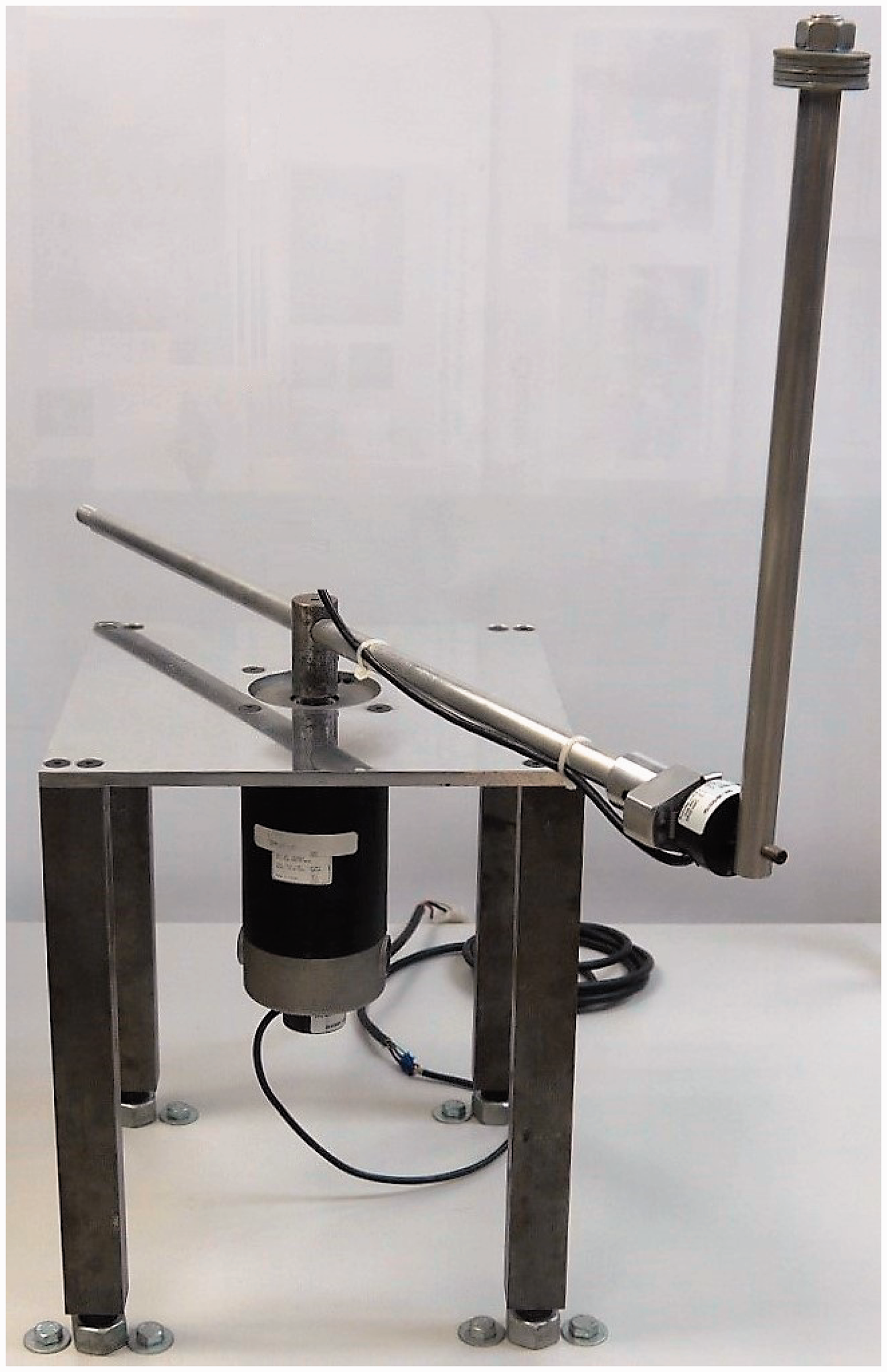
Furuta pendulum built at the Instituto Politécnico Nacional—CITEDI.
Identified parameters of the Furuta pendulum dynamic model in equation (1).
The joint velocities are estimated using the following algorithm

For the model-based controller in equation (12) and adaptive neural network controller in equation (17), the gains

For the adaptive neural network controller in equation (17), the number of neurons was L = 10, the matrix
Periodic oscillation I
A set of experiments by using the desired periodic oscillation

The results of the real-time implementation of the controller in equation (12) are given in Figure 4, which shows the performance of joint positions
Periodic oscillation I, model-based controller in equation (12). Left-hand side plot: time evolution of (a) q1(t) and (b) q2(t). Right-hand side plot: (c) applied torque τ(t).
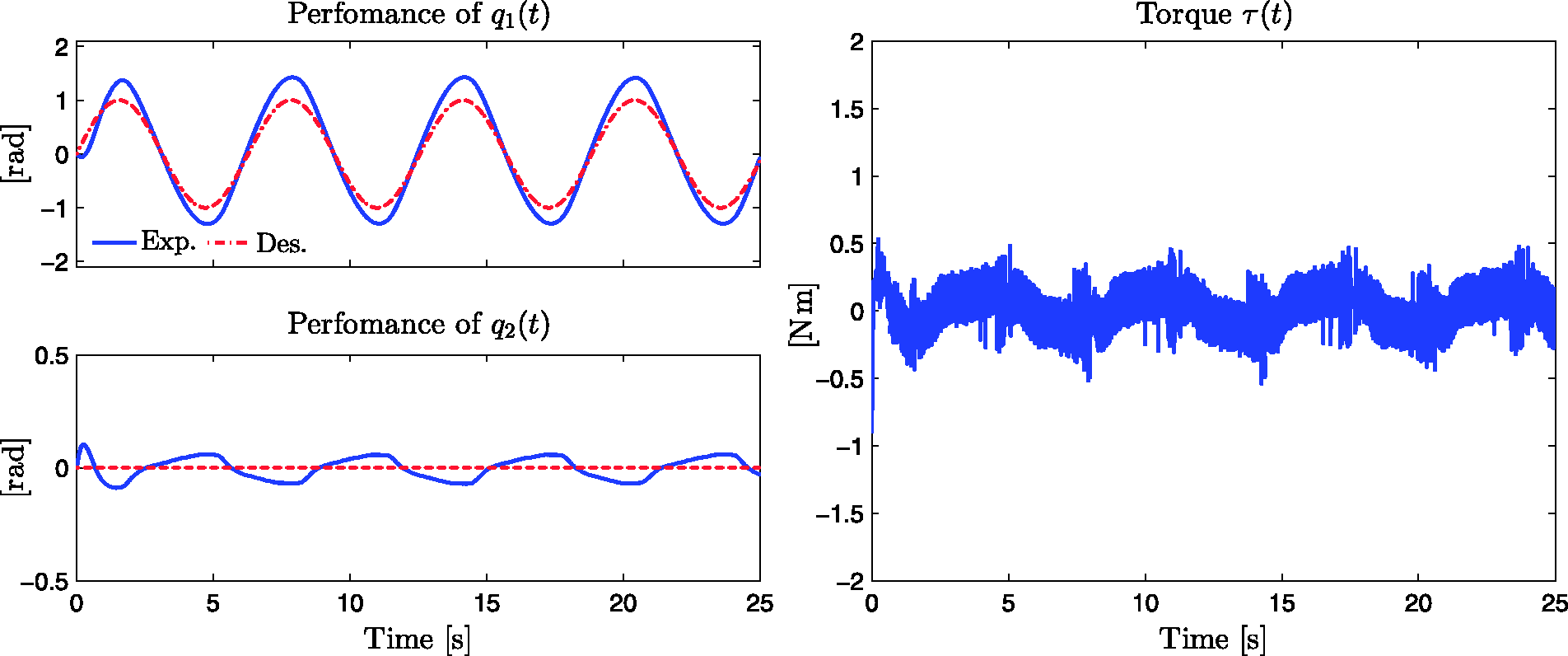
The new adaptive neural network controller proposed in equation (17), with signals
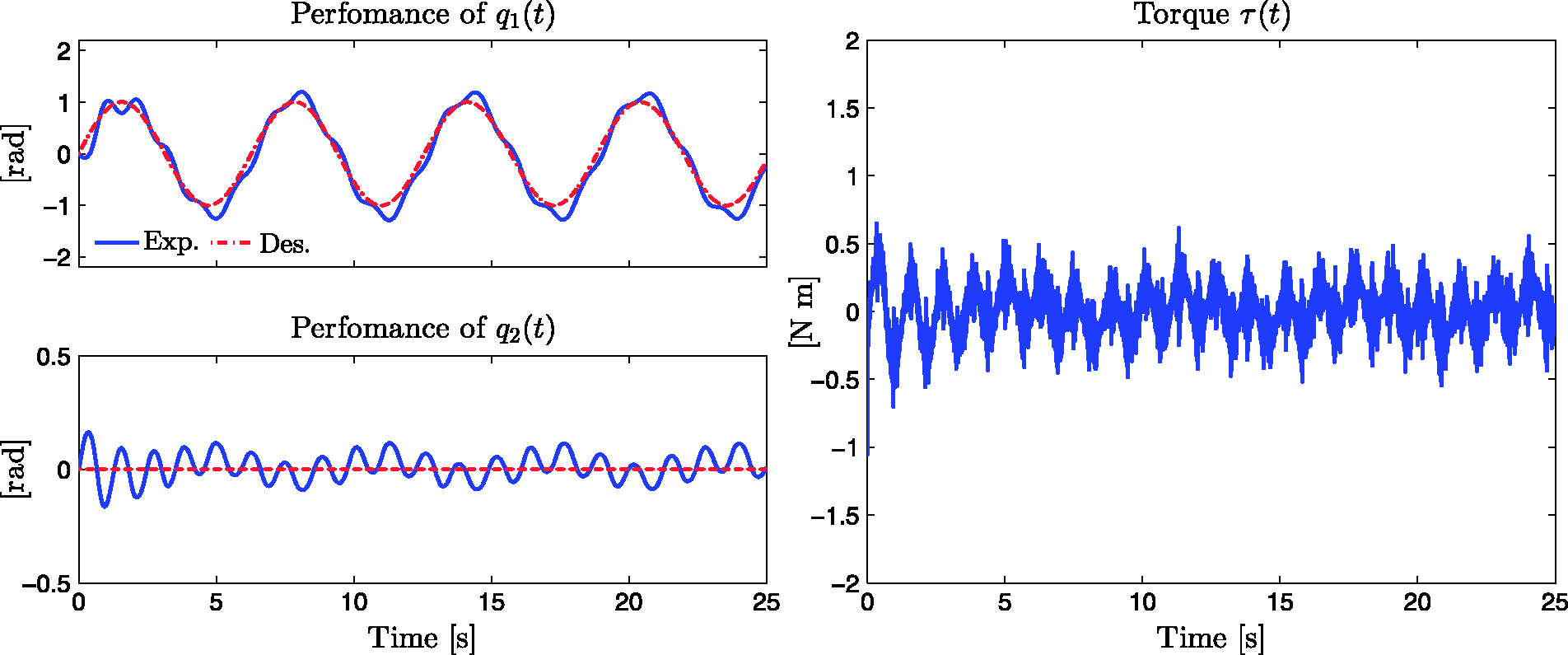
Periodic oscillation I, adaptive neural network controller in equation (17). Left-hand side plot: time evolution of (a) q1(t) and (b) q2(t). Right-hand side plot: (c) applied torque τ(t).
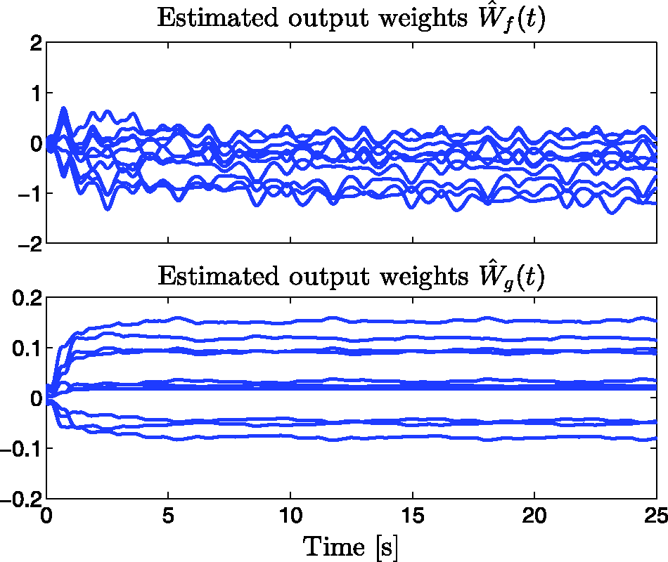
Periodic oscillation I, adaptive neural network controller in equation (17). Time evolution of the estimated output weights (a)
Periodic oscillation II
In this section, in order to show that the proposed controller is able to track a variety of periodic trajectories, a more complex desired trajectory was selected. By using the control gains in equation (41) in the model-based controller in equation (12) and the adaptive neural network controller in equation (17), we have carried out real-time experiments using the desired periodic oscillation

Results for the model-based controller in equation (12) are given in Figure 7, where the time evolution of joint trajectories q1(t) and q2(t), and the applied torque τ(t) are appreciated.
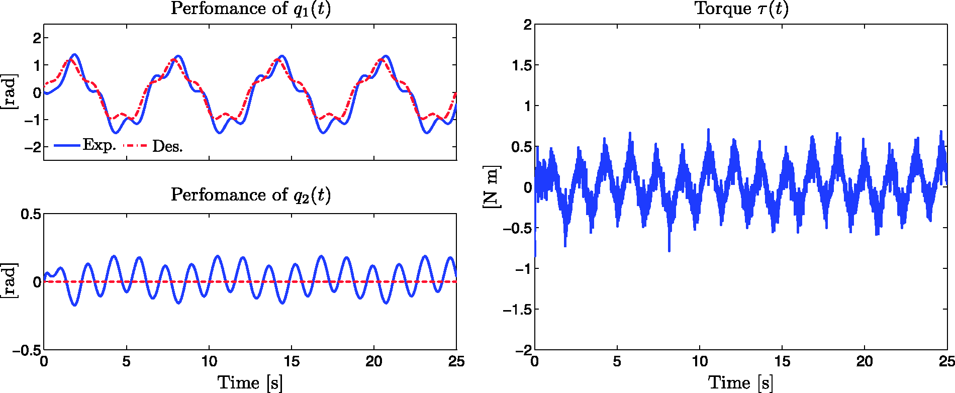
Periodic oscillation II, model-based controller in equation (12). Left-hand side plot: time evolution of (a) q1(t) and (b) q2(t). Right-hand side plot: (c) applied torque τ(t).
The results of the implementation of the adaptive neural network controller in equation (17) are given in Figure 8, which depicts the actual joint position trajectories q1(t) and q2(t), and the applied control action τ(t). Figure 9 describes the estimated weights
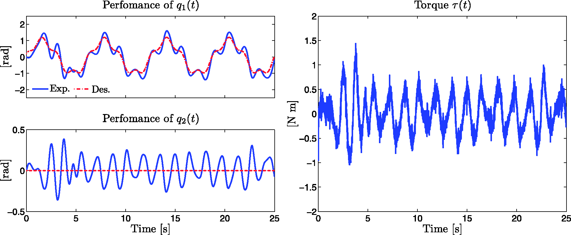
Periodic oscillation II, adaptive neural network controller in equation (17). Left-hand side plot: time evolution of (a) q1(t) and (b) q2(t). Right-hand side plot: (c) applied torque τ(t).
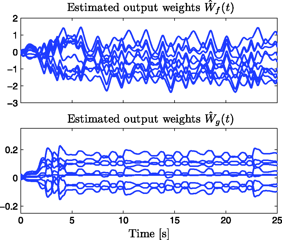
Periodic oscillation II, adaptive neural network controller in equation (17). Time evolution of the estimated output weights (a)
Note that in all experiments the applied torque τ(t) in Figures 4, 5, 7, and 8 exhibits high frequency components. The reasons of these high frequency components are the quantization noise introduced by the encoders and the discrete estimation of the joint velocity given by equation (40).
Performance comparison
In order to compare the performance of the implemented controllers, Figure 10 depicts the time evolution of errors
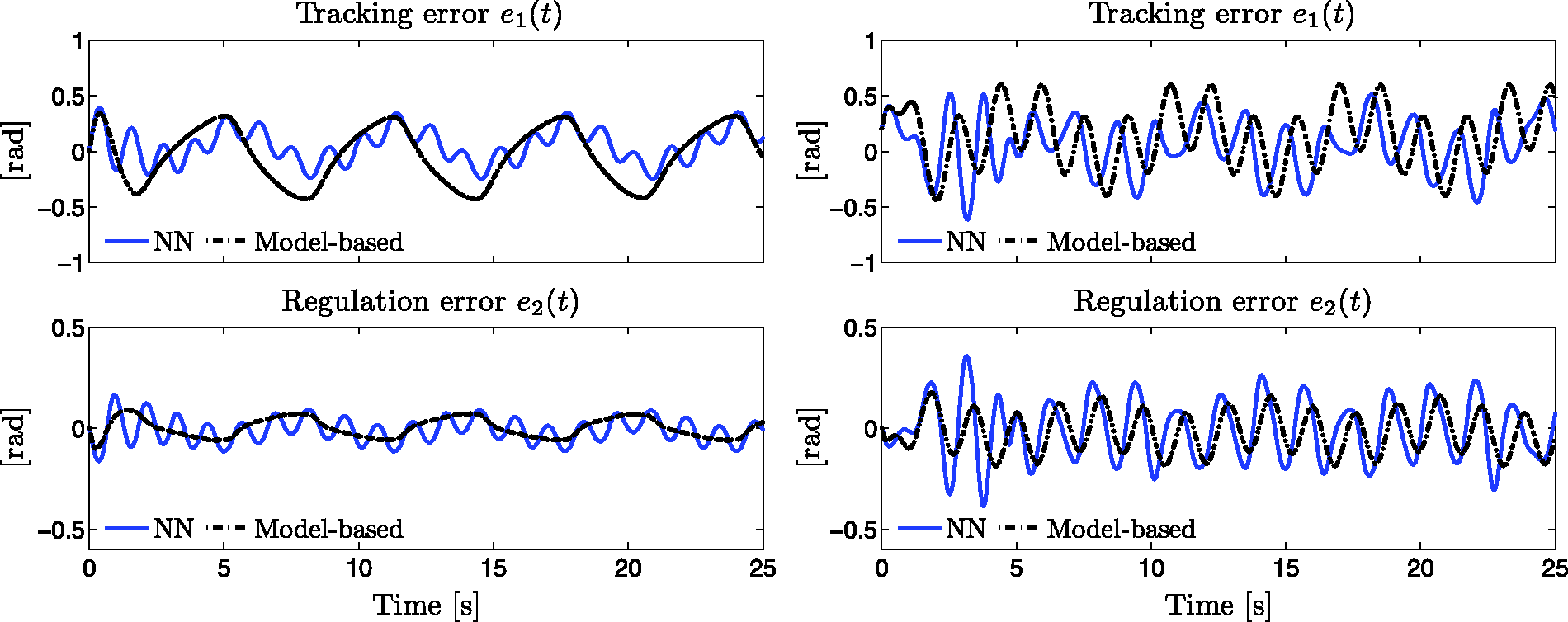
Comparison of the tracking errors (a), (c) e1(t) and (b), (d) e2(t) for the implementation of the model-based controller in equation (12) and the adaptive neural network controller in equation (17). Left-hand side plot: comparison of the errors for the periodic oscillation I. Right-hand side plot: comparison of the errors for the periodic oscillation II.
In order to assess the tracking performance of both controllers, the RMS values of the tracking error
Periodic oscillation I: RMS values of the tracking error signals
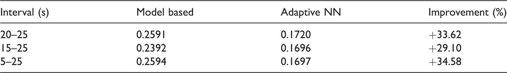
NN: neural network; RMS: root mean square.
Periodic oscillation II: RMS values of tracking error signals
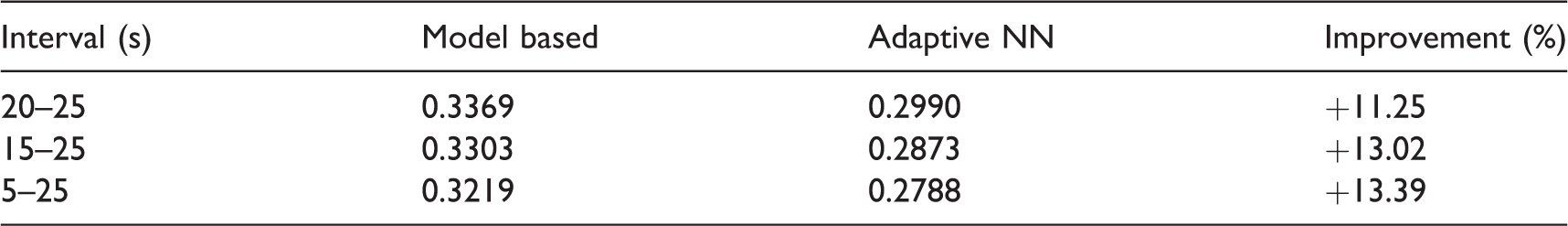
NN: neural network; RMS: root mean square.
The results observed in Figure 10, which shows the time evolution of
The improvement can be only explained due to the contribution of the adaptive neural network in the controller, which compensates other types of nonmodeled dynamics in equation (1), such as static friction, switching of the PWM servo amplifier, and vibrations in the mechanical structure of the mechanism.
Finally, in order to verify that the neural network contribution to the total applied torque is significant, Figure 11 shows the torque contributions for the model-based controller in equation (12) and the adaptive neural network controller in equation (17), which were separated as follows

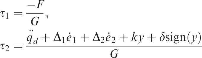
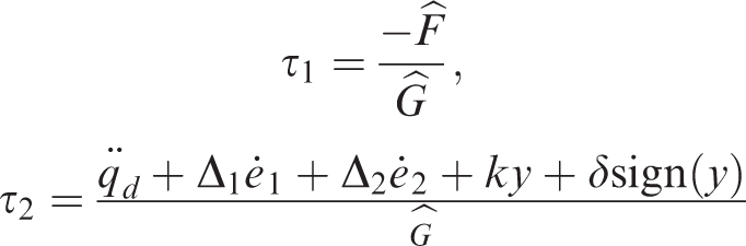
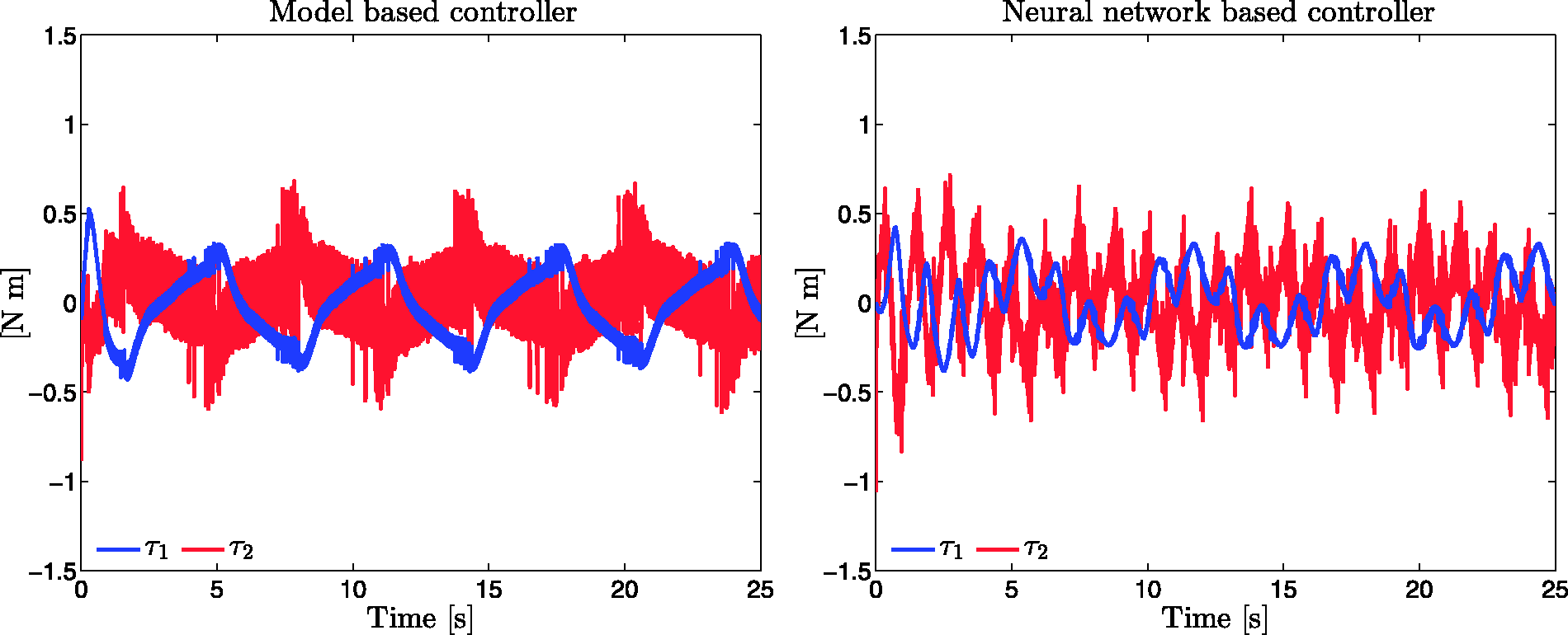
Torque contributions for the (a) model-based controller in equation (12) and (b) the adaptive neural network-based controller in equation (17).
As can be seen in Figure 11, the right-hand side plot shows that the neural network contribution
Conclusion
The main purpose of this document has been the introduction of a new controller in order to induce periodic oscillations in an underactuated system. The new scheme is based on adaptive neural networks, which has the advantage that the system model is not required to be known.
The new scheme is inspired from the feedback linearization technique and a novel output function y(t). The output function y(t) was chosen as a linear combination of the position errors and velocity errors.
An extensive real-time experimental study has also been presented, where a model-based controller is compared with the new adaptive neural network scheme. Two types of periodic oscillation were used in order to assess the adaptation capabilities of the new scheme. Better results were obtained with the new scheme since this is able to compensate disturbances and unmodeled dynamics.
Footnotes
Declaration of conflicting interests
The author(s) declared no potential conflicts of interest with respect to the research, authorship, and/or publication of this article.
Funding
The author(s) disclosed receipt of the following financial support for the research, authorship, and/or publication of this article: This work was supported by SIP-IPN, TecNM, and CONACYT Projects 176587 and 134534, Mexico.