
Abstract
This paper mainly studies the structure of a carbon fiber reinforced polymer floating raft frame and analyzes its vibration mode. A frame-based floating raft frame is designed, and two floating rafts which are made of carbon fiber reinforced polymer and metal materials, respectively, and have the same size and structure are manufactured. Based on the modal theory of vibration, the Abaqus software is used to carry out the finite element modal analysis of the frames which are made of different materials, and compare the low-order flexible frequency and vibration mode. Later, the experimental modal test results are verified with modal assurance criterion, and the modal experiment is conducted to verify the accuracy of finite element modal calculations. The results show that under the circumstance of the same frame vibration mode, the damping ratio of the carbon fiber reinforced polymer frame is much higher than that of the metal frame. In addition, the carbon fiber reinforced polymer frame presents good vibration absorption performance. The data analysis results provide some reference value for floating raft vibration designers.
Keywords
Introduction
Nassiri et al. 1 pointed out that the vibration can result in discomfort and annoyance of passengers, and affect the health. Yucel and Arpaci 2 proposed to avoid excessive ship vibration for passenger comfort and crew living. The vibration of the ship, in addition to unnecessary effects on humans, may also lead to fatigue failure of the local structural components or mechanical equipment failure. Huang et al. 3 pointed out that vibration isolation of the floating raft is developed on the basis of double-layer vibration isolation, and widely applied in various ships. Floating raft vibration isolation system can effectively reduce the mechanical vibration transmitted to the hull. The research on the floating raft system has attracted people’s attention in recent years. It is a new kind of vibration isolation and noise reduction system, where several mechanical vibration equipments are simultaneously installed on a common raft frame in the middle through the vibration isolator. Through the vibration isolator, the middle raft frame is mounted on the base of the hull. Among the adjustable design parameters of the floating raft, the parameters which have the greatest influence on the overall vibration isolation effect are parameters of the frame, including the quality, stiffness and damping ratio of the frame. At present, many researchers have studied the vibration isolation of ships. Preumont and Bossens 4 recommended a floating raft with truss structure. As a new structure, studies on the truss floating raft are still at the theoretical stage, and there is no wide range of practical applications. Xia et al. 5 studied the control of double-layer active vibration isolation in ships. Sun et al. 6 introduced the dynamic vibration absorber into the floating raft vibration isolation system. The results showed that the dynamic vibration absorber could significantly improve the floating raft isolation performance. Niu et al. 7 discussed the definitions of mechanical control, floating raft control and complete control and their mutual relationship. They pointed out that the control over the frame could effectively isolate high frequency and low frequency vibrations, and reduce the noise. By studying the influence of the Sandwich frame on the vibration of the raft, Choi et al. 8 found that the sandwich board could be used as the base of the frame to improve the vibration isolation performance of the floating raft. Li et al. 9 studied the stability of floating raft, and pointed out that the stiffness and mass ratio of floating raft was key to control vibration gain sensitivity. A modal analysis of a metal floating raft was carried out by Qu et al. 10 and Xiong et al. 11 The study exhibited that the frame was the central part of the floating raft system, and its vibration characteristics affected the vibration isolation performance of the whole floating raft system. Thus, it was necessary to conduct in-depth study on the vibration characteristics of the frame.
At present, the intermediate raft of floating raft vibration isolation system is mainly made of carbon steel or other metal materials, which has small damping and low specific rigidity. Carbon fiber reinforced polymer (CFRP) has been widely used in many fields, such as aerospace, sports building materials, medical equipment, etc. It has become the most important and commonly fiber reinforced material. The relationship between the structural properties of CFRP and the vibration isolation performance of raft is still to be studied, which is an urgent problem for the application of CFRP in vibration isolation system. The structure of the carbon fiber composite raft determines the mass and rigidity of the raft. In addition to a high specific strength and specific rigidity, it also has excellent damping characteristics, which is very useful for the vibration control and the improvement of bearing capacity for cycles and impacts. Concerning the design of the intermediate raft in the floating raft system, in addition to the structure, material and modal frequency, the modal shapes should also be considered in order to determine the installation location of the equipment and to prevent the equipment from being installed at the maximum amplitude. Ericson et al. 12 pointed out that modal analysis was a modern method of studying structural dynamics. It is the application of system identification method in engineering vibration field. Each mode has specific natural frequency, damping ratio and modal shape. These modal parameters could be obtained by calculation or experimental analysis, and such a computational or experimental analysis process is called modal analysis. If the analysis process is obtained by the finite element method, it is called the computational modal analysis. If the modal parameters are obtained by parameterizing the collected input and the output signals by conducting experiments, it is called the experimental modal analysis. Kumar and Sepahvand13,14 pointed out that the finite element method is an effective technique for analyzing vibration characteristics.
Starting from the structure of CFRP raft frame, this paper studies the natural frequencies, modes, and damping ratios of the first few free modes. In an important step for the raft to control the vibration transfer control in floating raft vibration isolation system, it is very important that, in order to improve the vibration isolation effect of vibration isolation system, the modal frequency of the first few modes should avoid the low frequency characteristic frequency of the vibration isolation system. Therefore, this paper firstly calculates and analyzes the finite element model of the raft frame on Abaqus software, and then verifies the accuracy of the finite element analysis by means of modal test. Finally, the modal parameters of CFRP raft and steel frame are compared. The results show that the CFRP raft has a good vibration isolation effect. It provides reference for the design of floating raft vibration isolation and can be used for reference in engineering design.
Structure of CFRP raft
The raft is most widely used in the floating raft isolation system. In this paper, the structure of the raft frame is flat plate.
Material selection
According to the performance requirements of the raft, PAN-based carbon fiber reinforced composites were selected and the winding shape of the species was chosen as T300. 15 Epoxy resin is the most commonly used matrix for carbon fiber composites, it has high temperature, good adhesion, corrosion resistance, and other characteristics. According to the selection of reinforcing materials and matrix materials, CFRP/epoxy resin (T300/5208) was chosen to fabricate CFRP raft.
Structure of CFRP raft
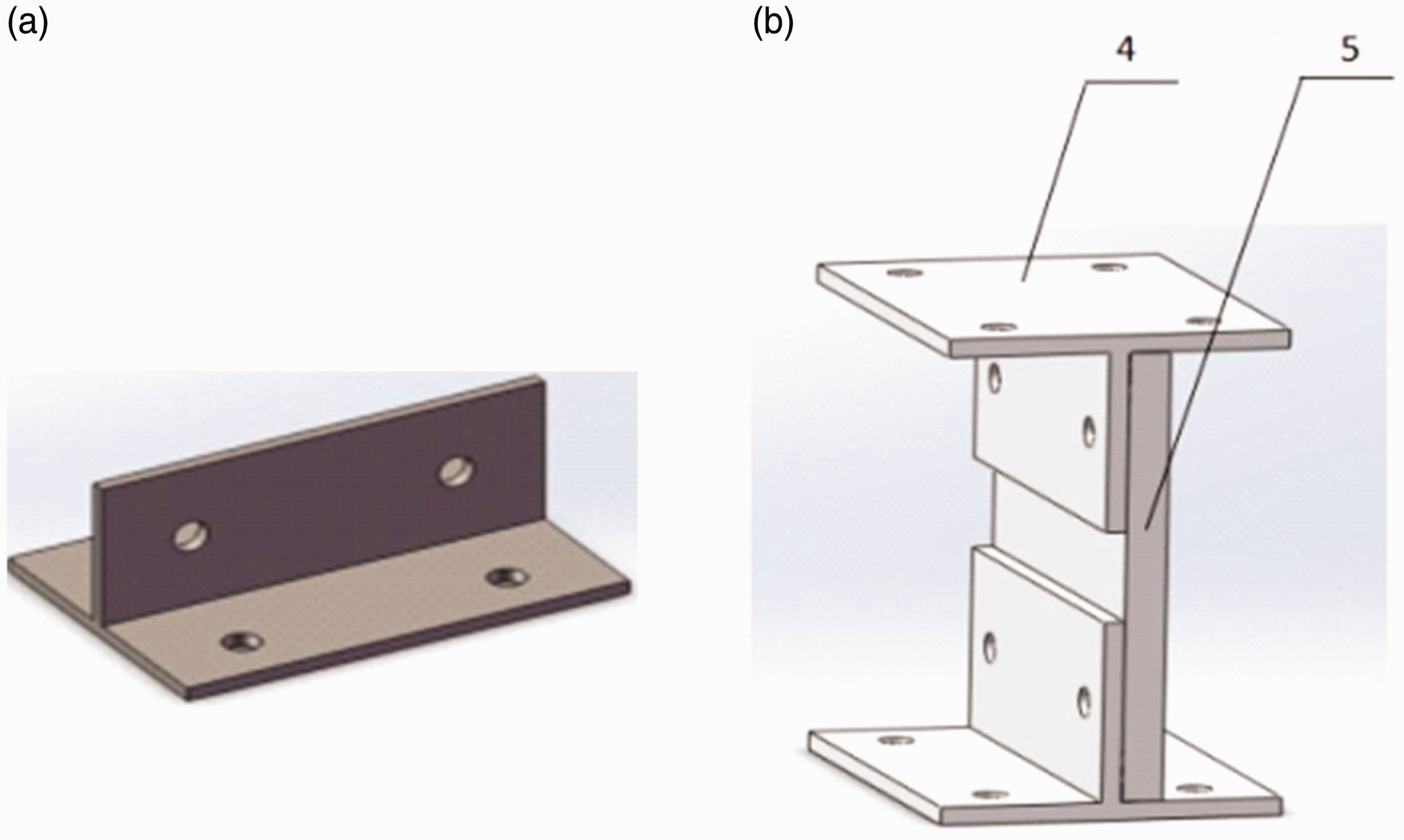
Figure 1 shows a three-dimensional structure of the raft. There are five main methods for CFRP structure connection: mechanical connection, adhesive connection, sewing connection, Z-Pin connection, and mixed connection. The adhesive is connected through the joint surface between the filler (glue). The rest are needed throughout the thickness of the connection, which resistance to peeling and splitting stress are very strong. The CFRP raft is subjected to a large tensile stress. The adhesive is not conducive to the transfer load, so the use of mechanical connection. At present, the typical connection forms of the commonly used orthogonal members include L-type connection, T-type connection, π-type connection, which are generally used for board-type components and beams, ribs, beams and so on. CFRP raft is subjected to out-of-plane tensile and compressive stress, which should be used orthogonal connection. In order to ensure the integrity of carbon fiber, steel T-shaped pieces and ribs made of “I” font structure, as shown in Figure 2. Then with 6 “I” font structure and the upper and lower CFRP plate bolted together is designed into CFRP raft.
Three-dimensional structure of the CFRP. 1, CFRP raft upper plate; 2, connecting piece; 3, lower CFRP plate.. CFRP frame connecting member. (a) T-shaped part and (b) “I”-shaped connecting body. 4, T-shaped part; and 5-ribbed plate.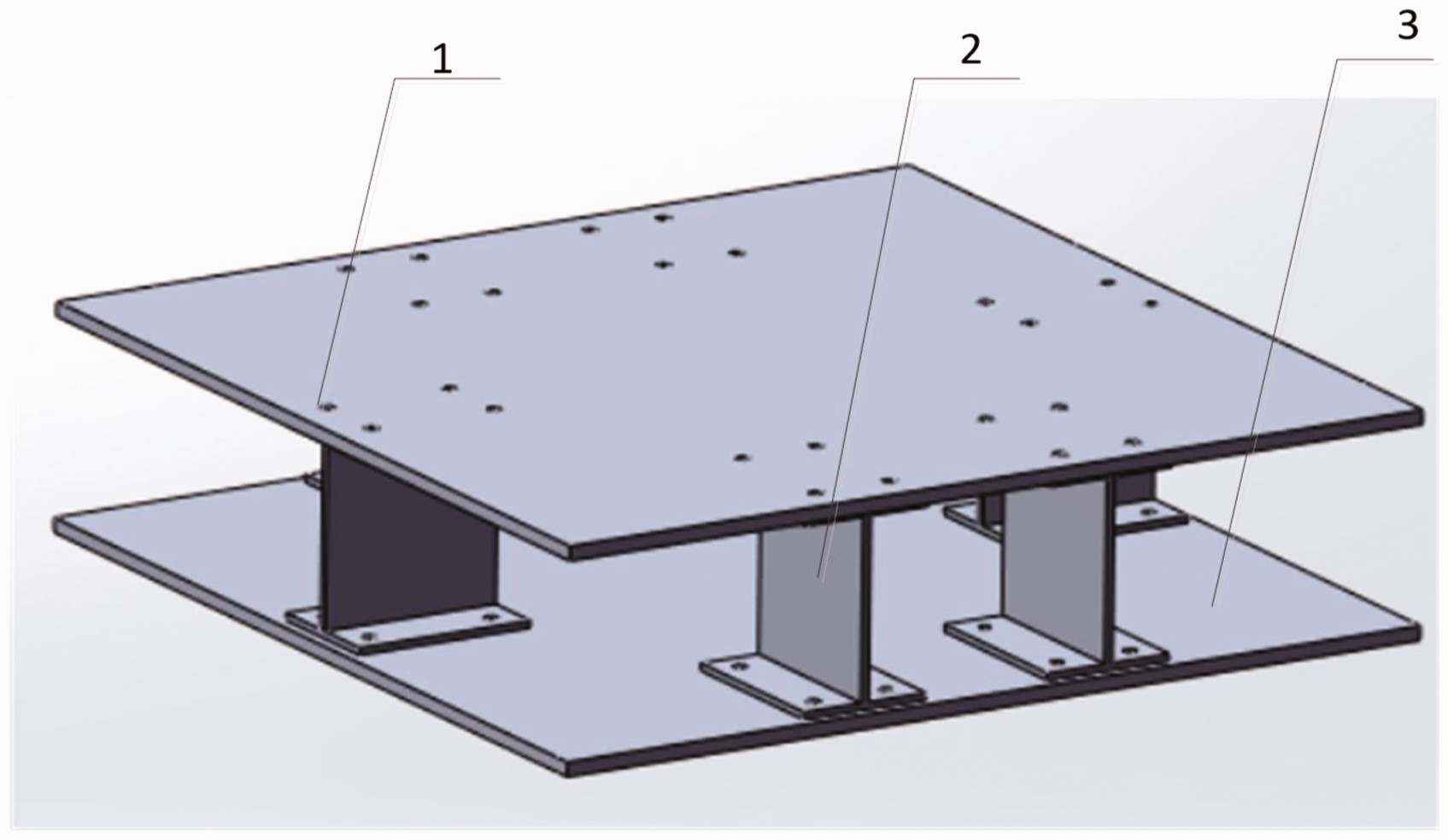
Modal analysis of raft
When the frequency of the excitation is the same as the natural frequency of raft, the raft is prone to resonance which can lead to premature bending fatigue failure. Therefore, in order to facilitate the optimization of the structure of the raft to avoid resonance, the modal analysis of the raft needs.
Basic theory of modal analysis
Alnefaie
16
pointed out that the modal analysis could determine the natural frequency and vibration mode of the known structure, and the natural frequency and vibration mode were important parameters of the structure design to withstand the dynamic load. In the mode analysis of Clarence,
17
the structure was dispersed as a model composed of finite elements. The unit stiffness matrix [K] and the unit mass matrix [M] are obtained. f(t) is the external load, and the unit damping matrix is [C]. Usually only the linear viscous damping can satisfy the simplified mathematical analysis. In the simplified kinetic model, other types of damping forms are usually replaced by an equivalent viscous damping. The differential equation of vibration for the cohesive damping system of raft is (1).

Fourier transform (1) is used to obtain the equation of motion in frequency domain


Equation (3) is impedance matrix. The reciprocal is transfer function matrix. From the vibration theory you can see that the linear time-invariant system, the response of any point can be expressed as a linear combination of the modal response of each order, freedom of the system is N, so the response to the i-point is written as a linear combination:


For a single point of excitation, set the excitation at point p, then the excitation force vector becomes equation (7).

rth order modal coordinates is equation (8).

In physical coordinates, the system response to any point i is equation (9).

Therefore, the frequency response function between the measurement point i and the excitation point p is equation (10).

After a slight transformation, transfer function is equation (11).


Modal assurance criterion (MAC)
Brehm and Pastor19,20 pointed out that modal assurance criterion (MAC) can represent the assurance level of the mode as is shown in equation (14)

Finite element modal analysis of raft
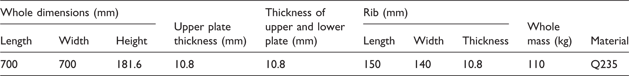
CFRP raft basic parameters.
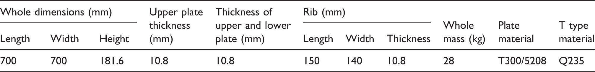
CFRP: carbon fiber reinforced polymer.
T300 CFRP plate mechanical parameters.
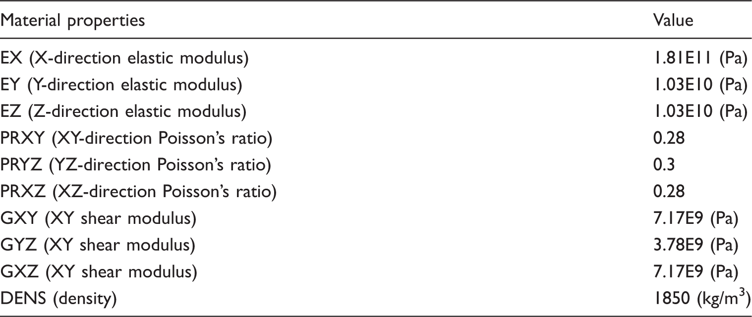
CFRP: carbon fiber reinforced polymer
Basic parameters of steel raft.
The finite element method which is the same method as CFRP is used to calculate the free modal of steel raft in Abaqus, and the results are verified by modal tests. Steel raft material selected ordinary carbon steel, the material properties: Young’s modulus is EX = 210 GPa, Poisson’s ratio PRXY = 0.3, density DENS = 7850 kg/m3. The meshes were divided into 103,240 units and the modal analysis was performed.
Modal test of raft
In order to verify the accuracy of the calculation results, modal test of the raft is conducted to compare with the results of finite element modal analysis. Because the boundary conditions of the finite element modal analysis of the raft are unconstrained, the modal test should also be. In the case of structural modal tests, it is difficult to accurately simulate the actual boundary conditions and the tests are basically set to “free state” which can be achieve by a soft rubber rope suspended or soft plastic foam supported.
In this paper, soft rubber rope suspended is used, AVANT MI-7016 data acquisition and analysis system produced by Hangzhou Yiheng Technology Co., Ltd is used to collect and analyze the data of the raft frame modal test. 5800B5 and test hammer of United States DYTRAN Instrument Company are used and B & K’s 11346-type unidirectional acceleration sensor is chosen. In this experiment, the acceleration sensor is arranged on the raft. The experimental device is shown in Figure 3.
CFRP modal experiment device.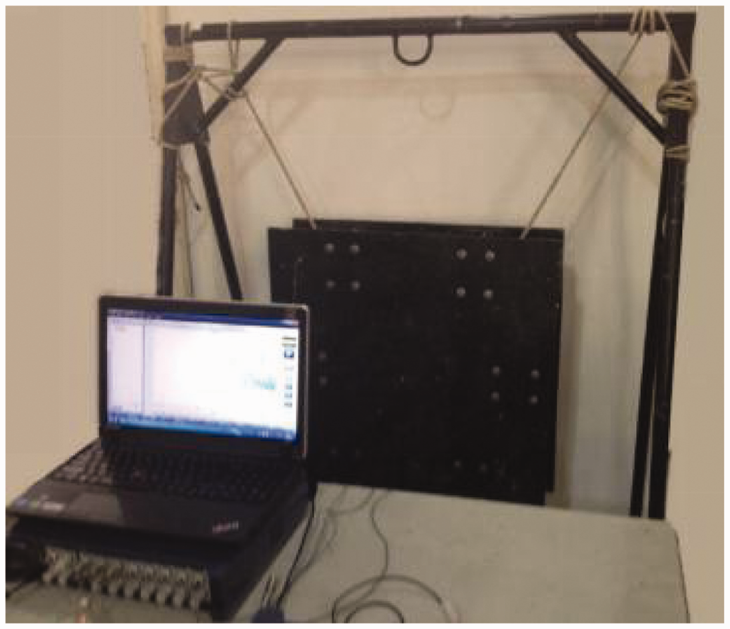
When the modal tests were conducted, the grid units were divided on the raft planes, 10 equal portions on each side and marked with chalk. The hammer is tapped on each of the marked nodes to measure the response values of the acceleration sensors at different strike points.
The data were imported into Modal Genius modal analysis software. The data were processed and fitted by Modal Genius software and the fitting curve of frequency response function of CFRP raft was obtained. And MAC was used to judge the assurance level of the mode.
Results and discussion
Finite element analysis
Finite element analysis of CFRP floating raft
Natural frequencies of the twelfth-order flexible mode of CFRP raft.

CFRP: carbon fiber reinforced polymer.
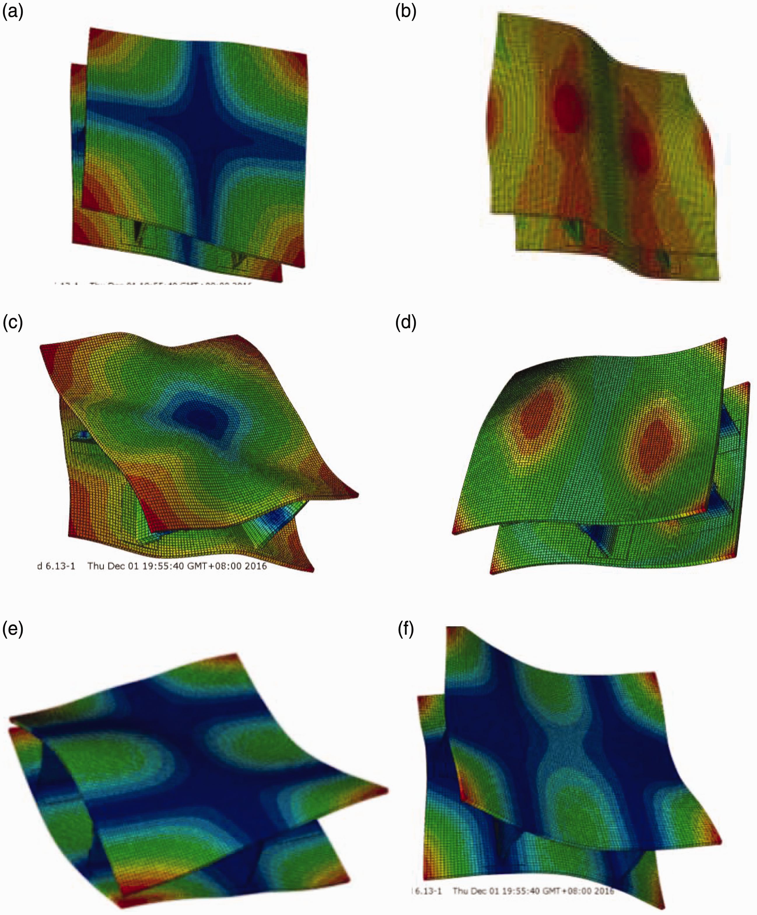
Flexible modal shapes of the first six orders of CFRP raft: (a) first-order vibration mode, (b) second-order vibration mode, (c) third-order vibration mode, (d) fourth-order vibration mode, (e) fifth-order vibration mode, and (f) sixth-order vibration mode.
Finite element analysis of metal raft
Natural frequencies of the twelfth-order flexible mode of steel raft.

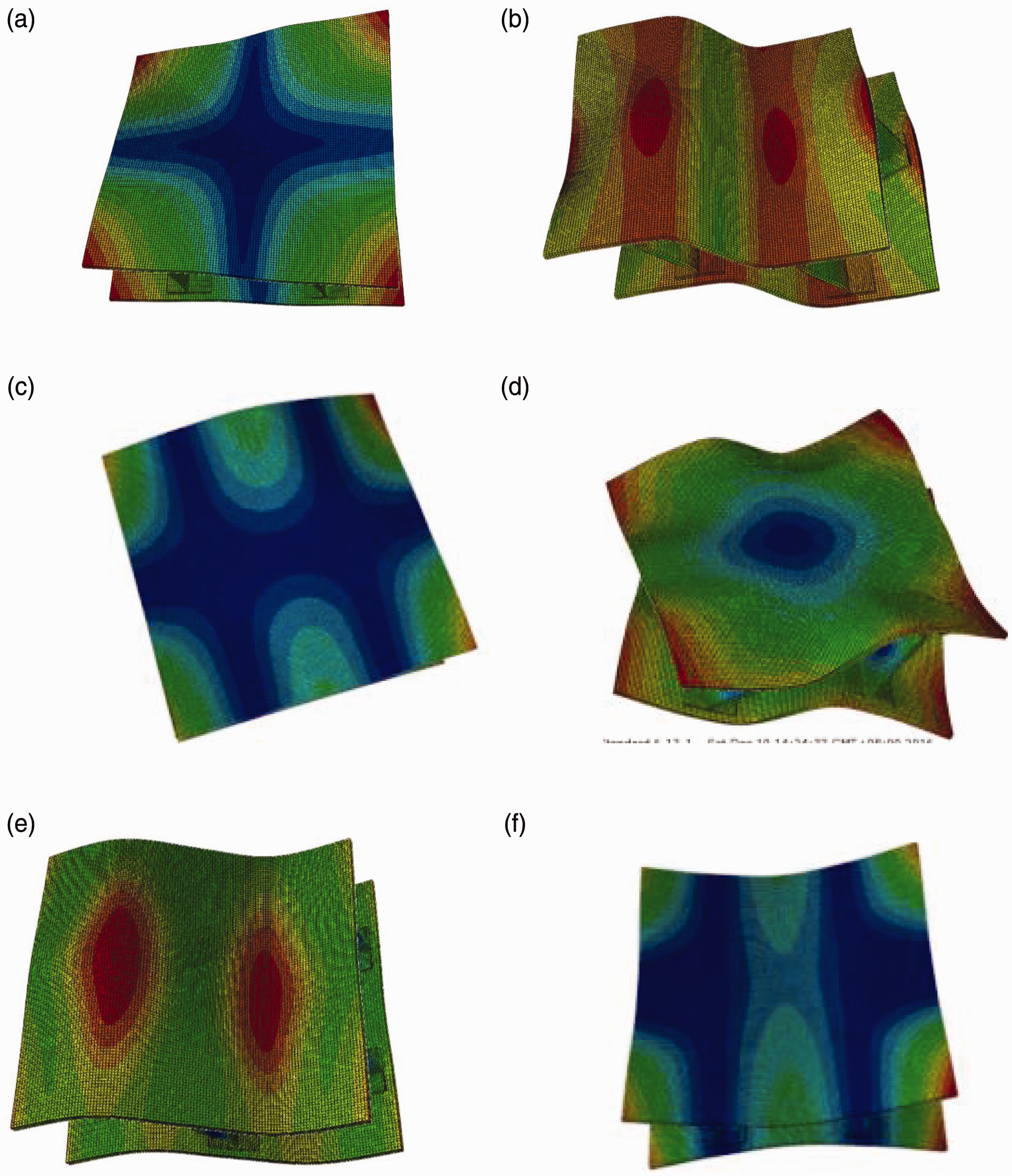
Flexible modal shapes of the first six orders of steel raft. (a) first-order vibration mode, (b) second-order vibration mode, (c) third-order vibration mode, (d) fourth-order vibration mode, (e) fifth-order vibration mode, and (f) sixth-order vibration mode.
Modal test and analysis
Modal test of CFRP raft
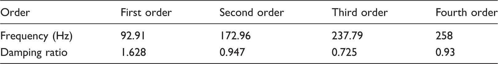
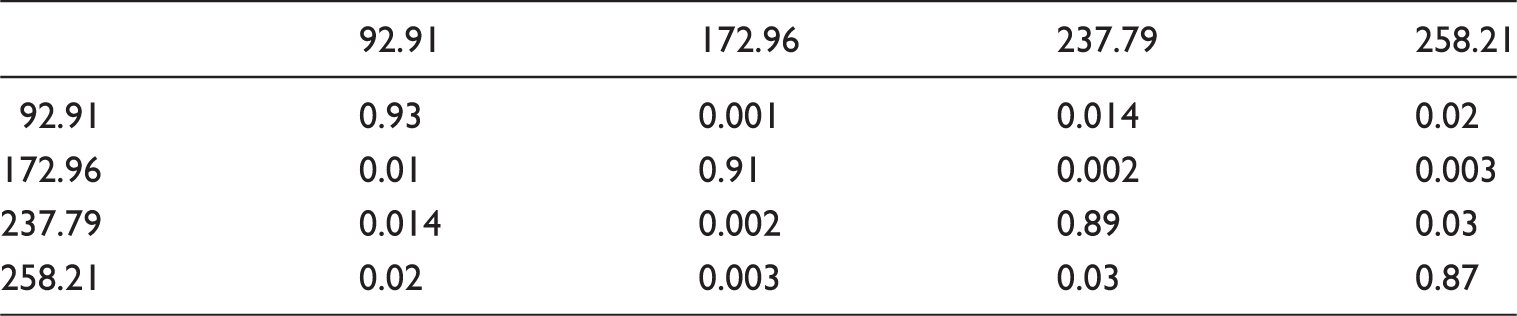
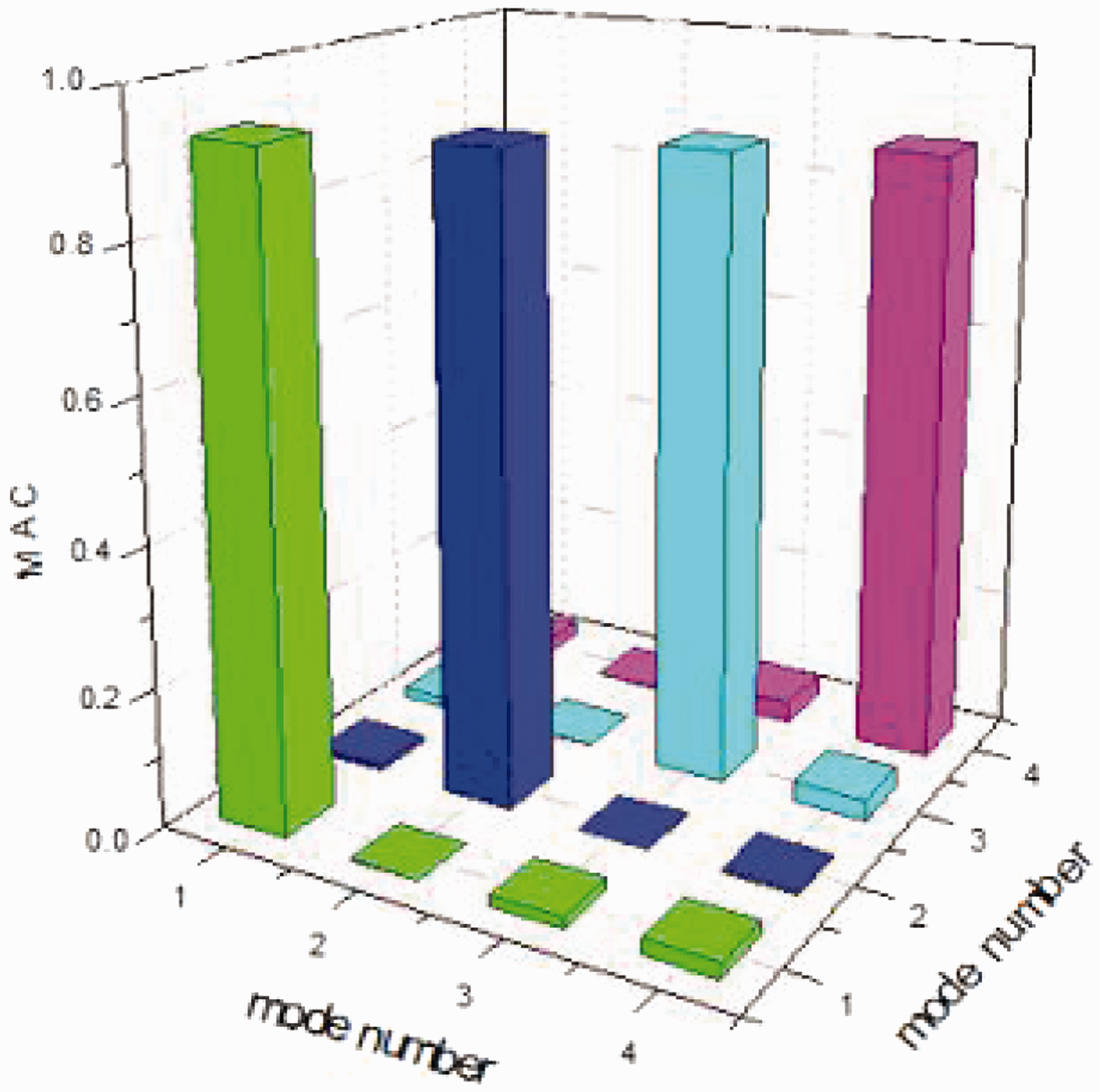
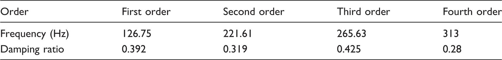
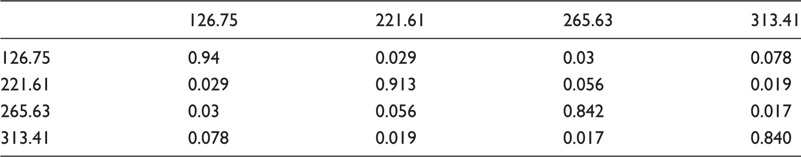
CFRP raft frequency response function fitting curve, as shown in Figure 6. The natural frequency (ω) and the damping ratio (ζ) fitting data are shown in Table 6. The modes of first four orders were obtained to conduct MAC assurance verification. The results can be found in Table 7 and Figure 7.
CFRP raft frequency response function curve. CFRP raft modal frequency (ω) and damping ratio (ζ). CFRP: carbon fiber reinforced polymer. MAC matrix of CFRP mode shapes. CFRP: carbon fiber reinforced polymer; MAC: modal assurance criterion. MAC of CFRPl raft.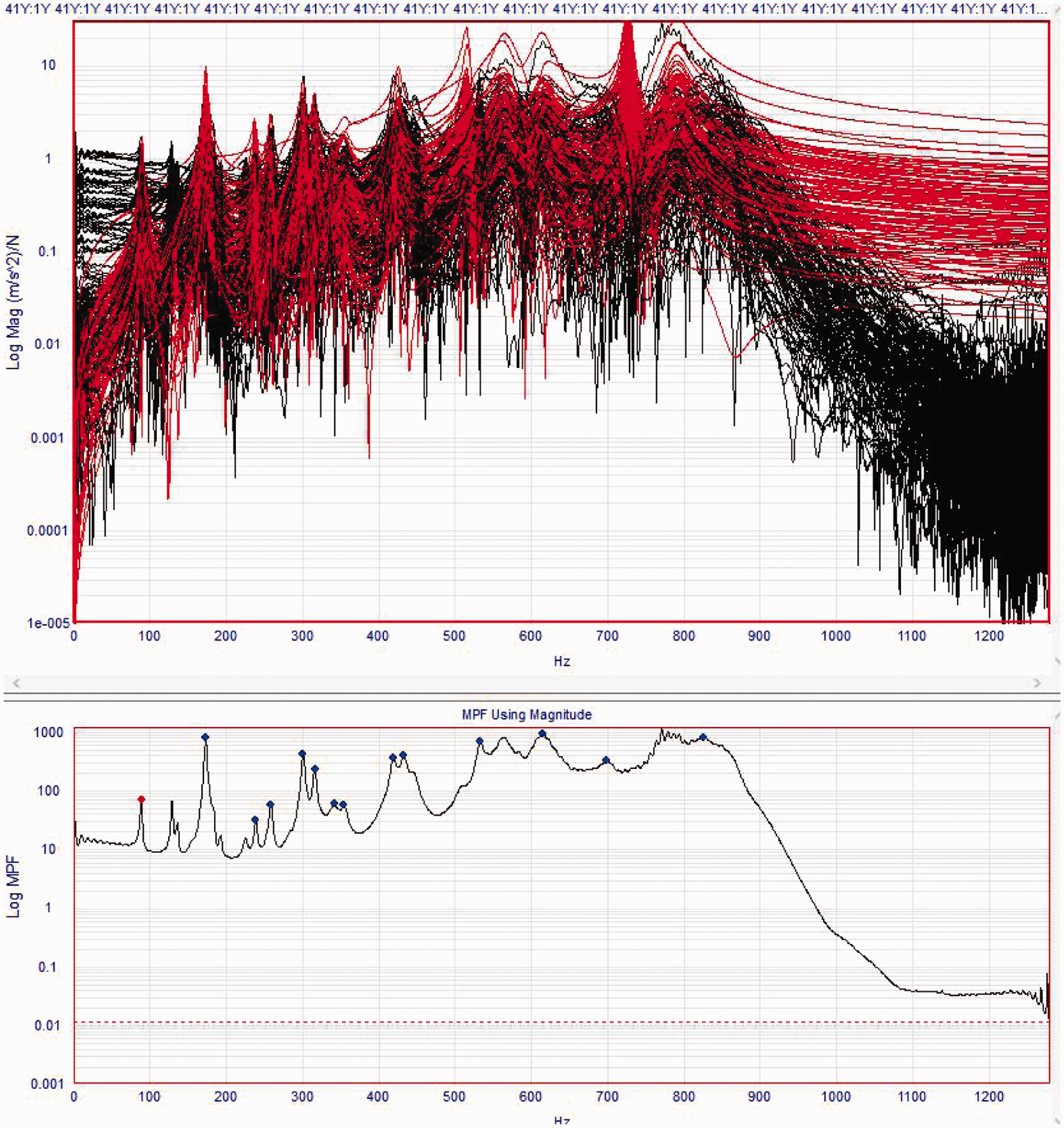
Modal test of steel raft
Table 8 shows the test results of the corresponding modal damping ratio (ζ) of the natural frequency (ω) of the steel raft. The modal frequencies of the first four orders of the steel raft frame were extracted for MAC assurance verification. The results can be found in Table 9 and Figure 8.
MAC of metal raft.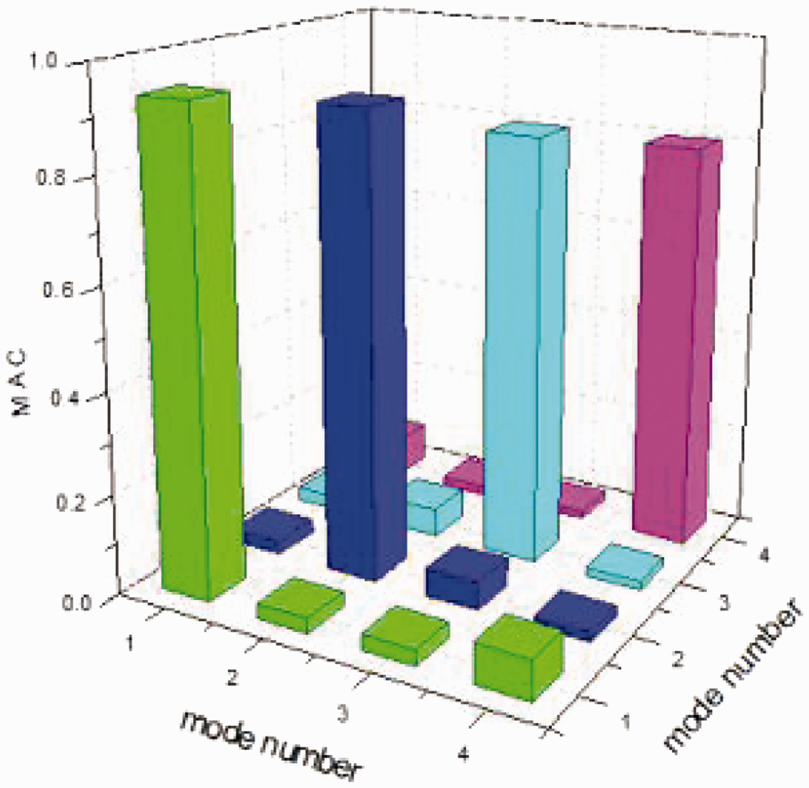
Steel raft modal frequency (ω) and damping ratio (ζ).
MAC matrix of steel mode shapes.
MAC: modal assurance criterion.
Comparison of finite element modes and experimental modes
Finite element and experimental modal frequency error of CFRP raft.
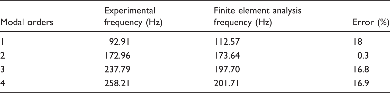
CFRP: carbon fiber reinforced polymer.
Finite element and experimental modal frequency error of metal raft.
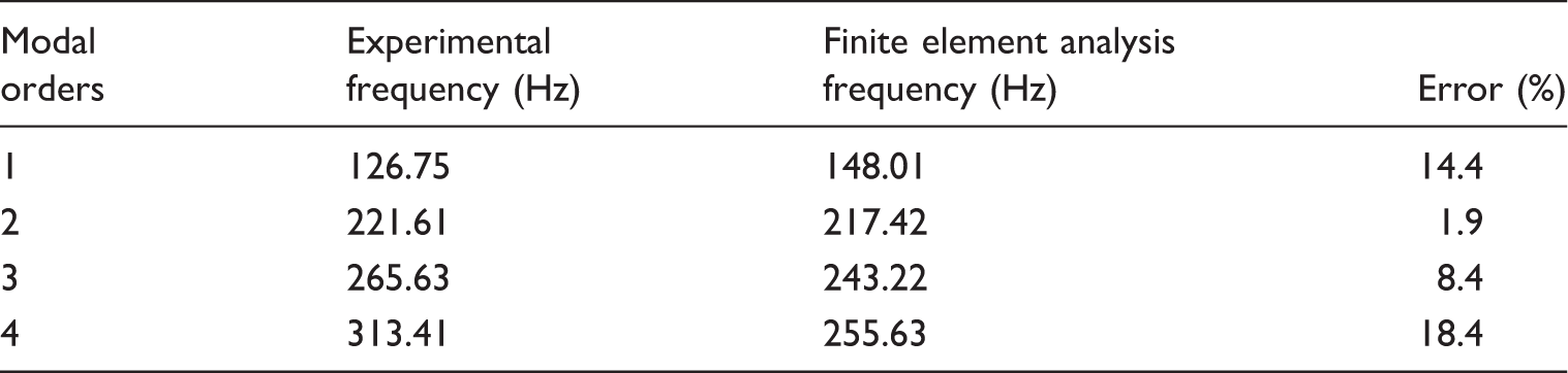
The test results of CFRP raft frame element analysis and modal test. It can be seen from Table 10 that the error between the natural frequencies of the raft frame at the first order and the third order is within 20%, and the error of the natural frequency of the raft frame at the second order is within 1%. Therefore, the established CFRP raft frame finite element analysis modal can basically reflects its natural vibration features.
It can be seen from Table 11 that error between natural frequency of the first three orders of the steel raft frame obtained by processing test data is within 19%. The established steel raft frame finite element analysis model can accurately reflect its natural vibration characteristics.
Modal analysis comparison of two materials
Analysis for the modal frequencies of carbon fiber raft frame and steel raft frame: by comparing Tables 4 and 5, it can be seen that when the sizes are the same, the first-order natural order of carbon fiber raft frame is 112.57 Hz, which is smaller than that of steel raft frame, which is 148.1 Hz. And the natural frequency of each order is smaller than that of steel raft frame. Analysis for the modal damping ratios of carbon fiber raft frame and steel raft frame: by comparing Tables 6 and 8, it can be seen that the modal damping ratio of CFRP raft frame is higher than that of steel raft frame. The first-order damping ratio of CFRP raft frame is approximately five times as much as steel raft frame. And the modal damping ratio of carbon fiber raft frame gets bigger as the modal order increases, while the modal damping of steel raft frame gets smaller as the modal order increases. By using larger damping structure in the floating raft vibration isolation device, the performance of floating raft vibration isolation can be improved. Analysis for the modal vibration shapes of carbon fiber raft frame and steel raft frame: it can be seen from Figures 4 and 5, the two materials mainly have bending and torsional deformation. The modal vibration shapes at the first order, the second order, and the sixth order of the carbon fiber raft frame and steel raft frame of the same size are basically the same. The modal vibration shapes of the third order, the fourth order, and the fifth order are different. This is mainly related to their natural frequency.
Conclusions
Based on the modal assurance analysis (MAC) of experimental modes, the experimental data were reliable. Through the finite element analysis and modal test analysis of carbon fiber raft frame and steel raft frame, the accuracy of finite element modal analysis was verified. The floating raft frames of carbon fiber and steel with same size and same structure were compared. The mass of carbon fiber raft frame reduced 75%. The frequency of carbon fiber raft frame reduced, while the damping ratio was multiplied. Therefore, the vibration absorption performance at low frequency was increased. This is helpful to improve the vibration isolation performance of the floating raft. By using the natural frequency and vibration shape of raft frame obtained by modal analysis, the resonance possibility and deformation and failure parts of the raft frame can be predicted. It provides a reference for the structural optimization design and the resonance avoidance of raft frame. The experimental test and finite element analysis has error because the connection between the parts of finite element analysis was rigid connection, and the structure of bolt connection was ignored. During the finite element simulation of CFRP raft frame, the existence of glue layer was ignored. Due to the existence of the bolted connection and glue layer of the CFRP raft frame and the connection relationship between the bolt and welding of the metal raft frame, the MAC modal assurance level of the experiment was lower.
Footnotes
Declaration of conflicting interests
The author(s) declared no potential conflicts of interest with respect to the research, authorship, and/or publication of this article.
Funding
The author(s) disclosed receipt of the following financial support for the research, authorship, and/or publication of this article: This work was supported by Research Project of Hubei Provincial Department of Education, China under Grant No. B2017188.