
Abstract
Planetary gearbox fault diagnosis is very important for reducing the downtime, maintenance cost, and for improving the safety, reliability, and lifespan of wind turbines. The present work reports the results concluded by long-term experiments to a defected planetary gearbox system, with a transverse cut with a depth of 1.0 mm and thickness of 0.2 mm to simulate the planetary gearbox component crack. For each defect, recordings every 60.0 min were acquired and a total of 7 recordings (∼ 6.0 h of test duration) were resulted until the termination of the test. Fault is assured by increasing the test period to the point of where the remaining metal in the tooth area has enough stress to be in the plastic deformation region. An experimental procedure is developed to assess the severity of the gearbox component fault. Gearbox components faults of cracked planet gear tooth, cracked planet gears carrier, and cracked main bearing inner race were tested under accelerated fault conditions, where a comparative analysis of condition monitoring indicators for various crack detection has been done. The experimental localized fault signals (vibration acceleration signals) were subjected to the same diagnostic techniques such as spectrum comparisons, spectral kurtosis analysis, skewness analysis, and crest factor analysis. The method is validated on a set of seeded localized faults on all gears and components: sun gear, ring gear, etc. The results look promising, where the root mean square value analysis could be a good indicator when compared with the other indicators in terms of early detection and characterization of faults.
Introduction
Structures and dynamics of planetary gears are very different from fixed axis gears and special attention is given to fault diagnostics of planetary gear system. In this paper, a distinctive nature of damage-induced vibration of planetary gear box, namely tidal frequency, considering fault transmission paths of planetary gear system is discussed and proposed. Artificial planetary sun gear fault is introduced to an experimental test rig, and the proposed tidal frequency for planetary sun gear faults is demonstrated, which may be a promising feature for the planetary gear system condition monitoring.1,2
With the widespread application of wind turbines, their maintenance is a growing concern. Bearings play a critical role in industrial applications and it is necessary to effectively monitor their health status. The shock pulse method (SPM) can detect the incipient fault of bearings and prevent the fault consequence effectively. However, many researchers used laboratory data to validate the SPM. This study mainly concentrates on the SPM application on the bearing fault detection of wind turbines. Shock pulse signals are derived from the gearbox of industrial wind turbine test rig by SPM instrument. According to the frequency spectrum analysis, the bearing fault has been accurately detected and located. The analysis results demonstrate that the SPM technology was potentially effective for detecting the bearing faults of the industrial wind turbines.3,4
The important issue in planetary gear fault diagnosis is extracting the dependable fault characteristics from the noisy vibration signal of planetary gearbox. This critical problem was addressed by an envelope manifold demodulation method, which was proposed for planetary gear fault detection. This method combines complex wavelet, manifold learning, and frequency spectrogram to implement planetary gear fault characteristic extraction. The vibration signal of planetary gear was demodulated by wavelet enveloping. The envelope energy was adopted as an indicator to select meshing frequency band. Manifold learning was utilized to reduce the effect of noise within meshing frequency band. The fault characteristic frequency of the planetary gear was shown by the spectrogram. The planetary gearbox model and test rig were established and experiments with planet gear faults were conducted for verification. All results of the experiment analysis demonstrate its effectiveness and reliability.5–8
Planetary gearbox fault diagnosis has been done mostly through vibration analysis over the past years. Vibration signals theoretically have the amplitude modulation effect caused by time-variant vibration transfer paths due to the rotation of planet carrier and sun gear, and therefore their spectral structure was complex. It was difficult to diagnose planetary gearbox faults via vibration analysis. Strain sensor signals on the other hand have less amplitude modulation effect. Thus, it was potentially easy and effective to diagnose planetary gearbox faults via strain sensor signal analysis. A research investigation on planetary gearbox fault diagnosis via strain sensor signal analysis was reported. The investigation involved using time synchronous average technique to process signals acquired from a single piezoelectric strain sensor mounted on the housing of a planetary gearbox and extracting condition indicators for fault diagnosis. The reported investigation included analysis results on a set of seeded fault tests performed on a planetary gearbox test rig in a laboratory. The results have showed a satisfactory planetary gearbox fault diagnostic performance using strain sensor signal analysis.9–13
A technique for detecting faults in variable speed wind turbines with permanent magnet synchronous generators was proposed. The proposal consists on sampling and process vibration signals at constant position intervals, in order to obtain a speed independent vibration spectrum. The angular position information is obtained using a reduced-order observer, which allows estimating rotor position using voltage and current measurements, without the need of a position sensor. The estimated position was used for re-sampling vibration signals at constant position intervals with a high number of samples per revolution. Experimental results including a rotor imbalance fault were presented to validate the proposal.14–18
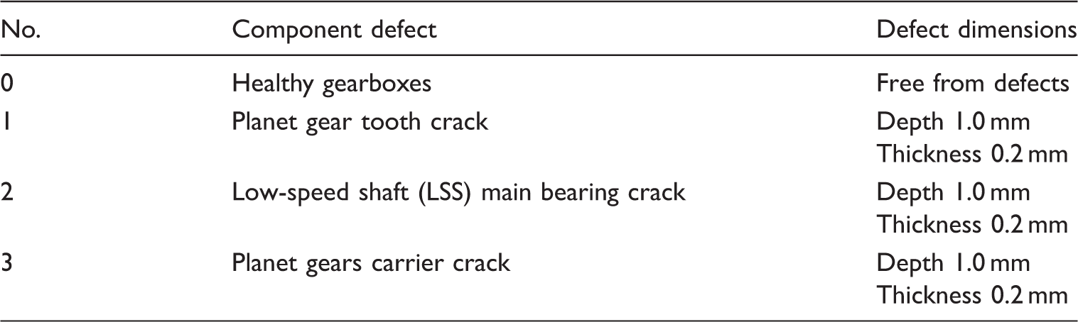
In this paper, a comparative analysis of condition monitoring indicators for various crack detection has been done. A crack has been simulated on planetary gear tooth root, planet gears carrier, and main bearing inner race. The experimental methodology is briefly introduced and the information about the experimental investigation is tested under accelerated fault conditions at different speeds and load cases. Moreover, an experimental procedure is developed to assess the severity of the gearbox component fault. The cracks specifications have been introduced. The experimental localized fault signals (vibration acceleration signals) were subjected to the same diagnostic techniques such as spectrum comparisons, spectral kurtosis analysis, skewness analysis, and crest factor analysis. Finally, the present work reports the results obtained by long-term (∼6.0 h) experiments to a defected planetary gearbox system, with a transverse cut with a depth of 1.0 mm and thickness of 0.2 mm to simulate the planetary gearbox components crack.
Condition monitoring indicators
Planetary gearbox components condition indices process the vibration of the wind turbine gearbox to return a single value indicating its overall health. This signal could be either increasing or decreasing as the gearbox damage (crack or pit) increases. The vibration signal of a defective gearbox usually considers being amplitude modulated at characteristic defect frequency. Matching the measured vibration spectrum with the defect characteristic frequency enables the detection of the presence of a defect and determines where the defect is. Figure 1 shows a description of the traditional diagnostic scheme.
19
Traditional planetary gearbox diagnostics scheme.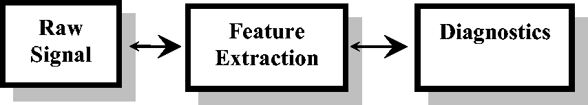
Root mean square
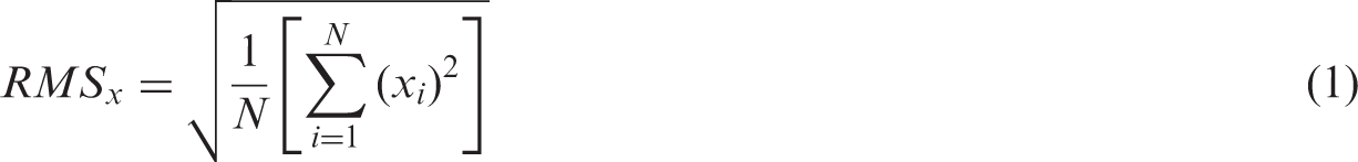
Root mean square (RMS) signifies the energy content within a signal with respect to time. The RMS is defined as the square root of the mean of the sum of the squares of signal samples. It measures the magnitude of a discretized signal and is given by
Skewness
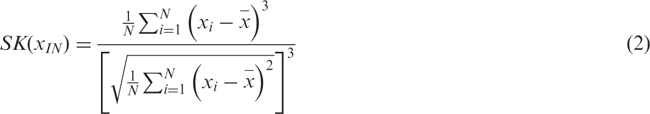
Skewness, SK (x
IN
) measures the asymmetry of the data about its mean value. A negative SK value and positive SK value imply that the data have a longer or fatter left tail and a longer or fatter right tail, respectively.
Kurtosis
Kurtosis (KT)is the fourth-order moment normalized by the square of variance of a signal and gives a measure of the peakedness of the signal. It measures the peakedness, smoothness, and the heaviness of tail in a data set and is given by
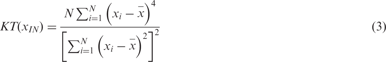
For a healthy gear vibration signal, kurtosis is approximately 3.
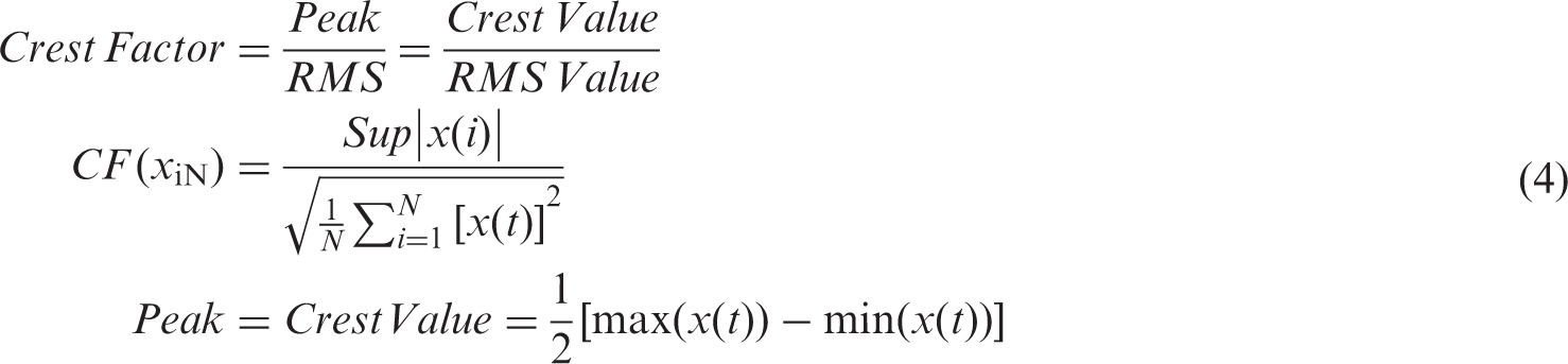
Crest factor
Crest factor (CF) is defined as the ratio of the peak value to the RMS of a signal and in other terms is equal to the peak amplitude of a waveform divided by the RMS value. The purpose of the crest factor calculation is to give an analyst a quick idea of how much impact is occurring in a waveform.
Higher order statistics indices
From the previous discussion, descriptive and higher order statistics (HOS) indices have been generating intensive interest. The RMS, average crest factor, and kurtosis values calculated from the measured signal have nearly similar trend, where the RMS value is found to be a better indicator when compared to either average crest factor or kurtosis. The RMS values of rotational vibration acceleration are used to evaluate the wind turbine gearbox components faults severity assessment. Component fault health level (CFHL) can be calculated based on the following equation

Experimental methodology
Background
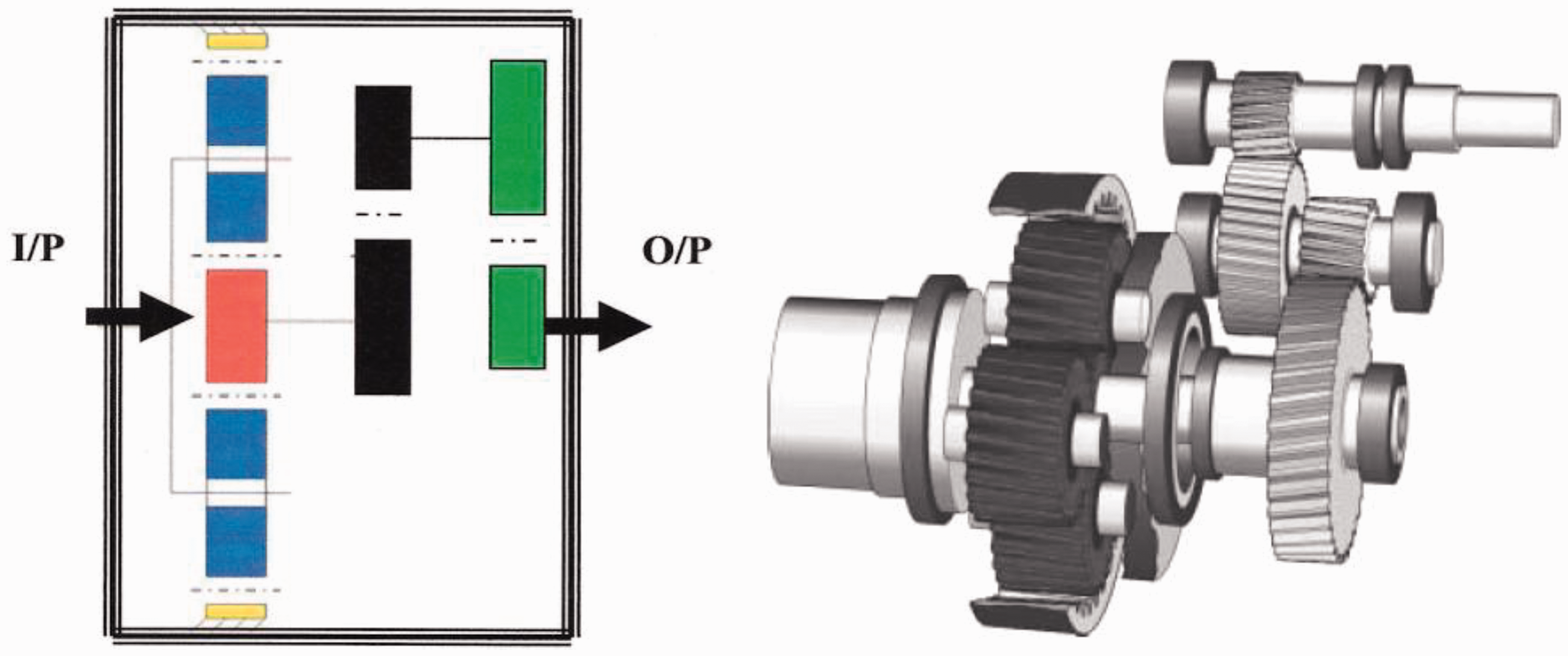
A wind turbine gearbox has three stages, where the first stage is planetary and the second and third stages are helical. The difference in the size of the wheels is equal or over 1:5 in the first stage, while the difference in size of the wheels is also equal or over 1:5 in the second and third stages. When the two ratios are combined, the output shaft will turn equal or over 25 times for every rotation of the hollow shaft (input) and the main shaft of the wind turbine combined. One can say that the gearbox has a gear ratio of 1:25. Normally, the ratio in every set of gearwheels is restricted to about less than 1:6. If the 150 kW wind turbine has a rotor rotational speed of 40 r/min with a generator speed of about 1000 r/min, the gearbox must have a total gear ratio of 40/1000 or 1:25. This is possible using a three-stage gearbox (one planetary stage and two helical stages (Figure 2)).
Wind turbine gearbox
20
.
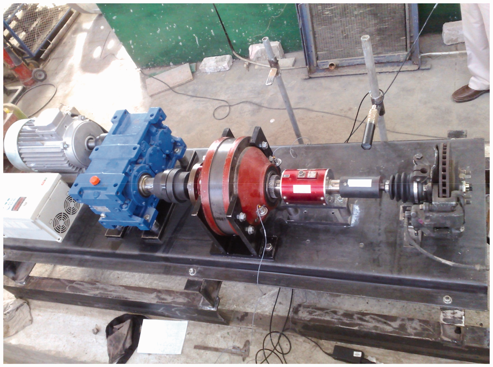
Test rig layout
Figure 3 shows a photograph of the layout of the test rig which will be used for the vibration analysis in the detection, quantification, and advancement monitoring of fault incurred by wind turbine gearbox components. The tested wind turbine gearbox is the same as the one described above (it contains three stages), where the first stage is planetary and the second and third stages are helical. Owing to the difficulties of obtaining a real gearbox in one unit, two separate units are considered namely, one planetary gearbox and one helical gearbox. Both gearboxes (planetary and helical) are connected by flexible coupling producing one combined gearbox. The axes of the gears either of planetary gearbox or helical gearbox are supported by two bearings each. Either the planetary gearbox or the helical gearbox system is settled in an oil basin in order to ensure proper lubrication. SAE 90 oil was used as a lubricant where the full lubrication level is 100 mm and half lubrication level is 50 mm. The combined gearbox is powered by an electric motor and consumes its power on a hydraulic disc brake. A short shaft is attached directly to the shaft of the motor to minimize the effects of misalignment and transmission of vibration from motor. The shaft is supported at its ends through two bearings and then the motion is transmitted directly to the gearboxes. The system characteristics are as follows:
Stage 1 – planetary gearbox with three planet gears Stage 2 – helical gearbox with four helical gears Stage 3 – phase 11 kW motor (220 V, 50 Hz, 1400 r/min) controlled by an inverter Hydraulic disc brake The shafts are bearing supported Photograph of the test rig layout.
Experimental procedure
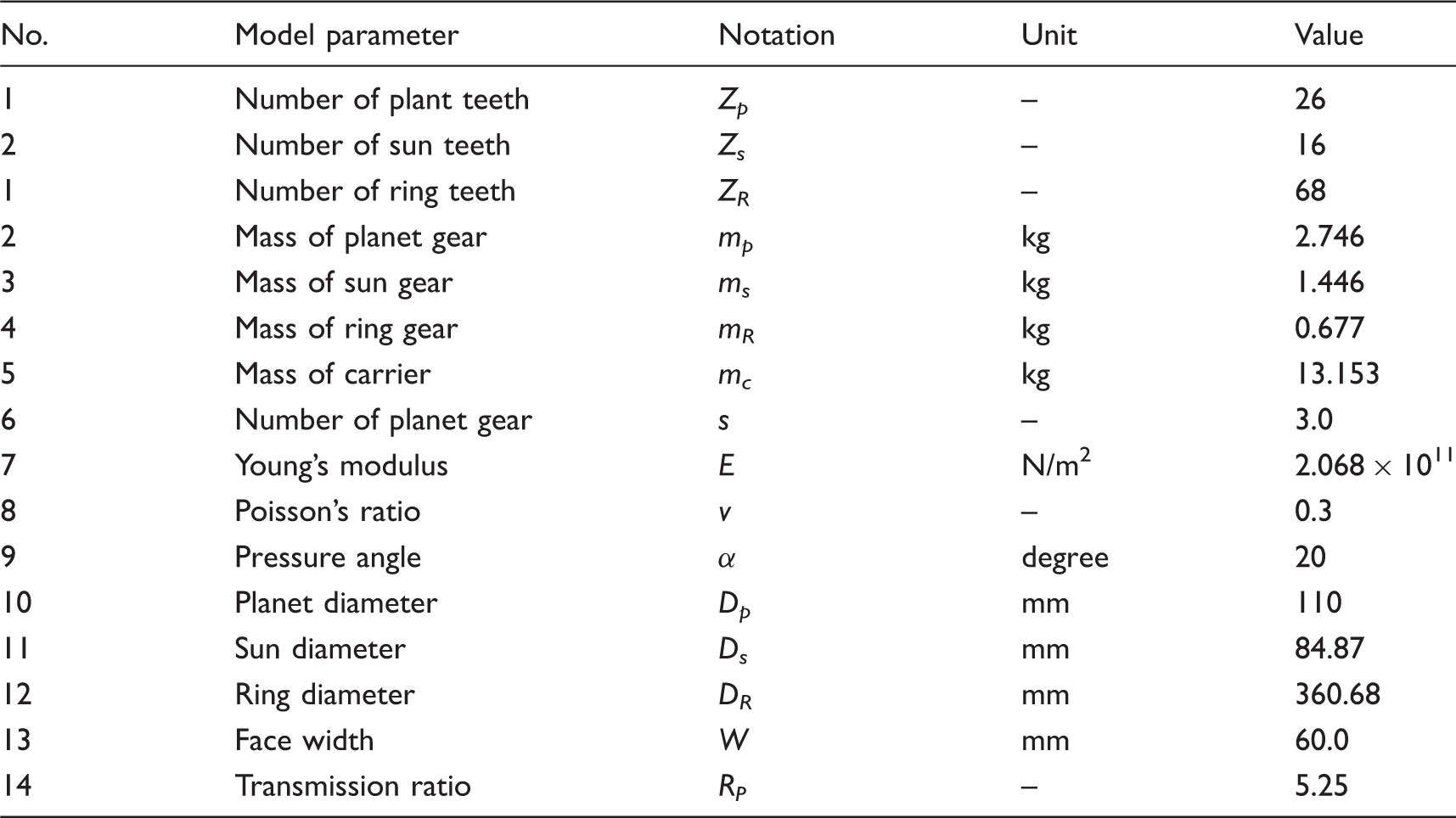
Technical data for planetary gearbox (3 planet gears, 1 sun gear, 1 rig gear).
One nondestructive technique has been employed to record the gearbox during operation, namely vibration acceleration generation. Two Bruel & Kjaer accelerometers were used for the vibration acceleration signals recording both mounted upon the gearbox case, one in each side-axis. The sampling frequency used was 6.0 kHz and signals of 1.0 s duration were recorded. B&K portable and multichannel PULSE-type 3560-B-X05 analyzer is used (see Figure 4). The B&K PULSE labshop is the measurement software type 7700 that is used to analyze the results. The speed is measured by a photoelectric probe. Recordings were carried out at constant speed.
Portable and multichannel PULSE.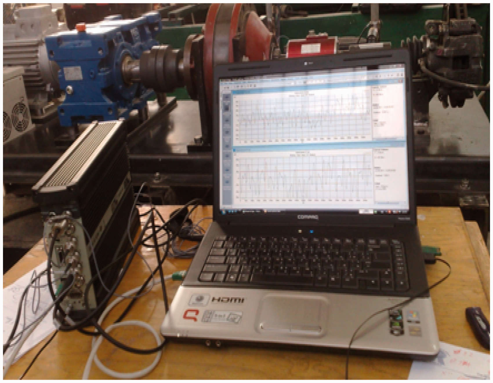
It is well known that most of the motions in the gearbox are rotational. On the other hand, it is a fact that 50% of all coordinates are rotational (as opposed to translations) and 75% of all frequency response functions (FRF) involve rotational coordinates. However, it is extremely rare to find enough references to methods for the measurement of rotational responses and this reflects the fact that virtually none are made. This situation arises from a considerable difficulty encountered when trying to measure either rotational responses or excitations and also when trying to apply rotational excitation, i.e. an excitation torque.
There are basically two problems to be tackled: the first is that of measuring rotational responses and the second is a companion one of generating and measuring the rotational excitations. The first of these is the less difficult and a number of techniques have been evaluated, which use a pair of matched accelerometers placed a short distance apart on the gearbox's structure to be measured as presented in Ewins. 21
Wind turbine planetary gearbox components defects dimensions.
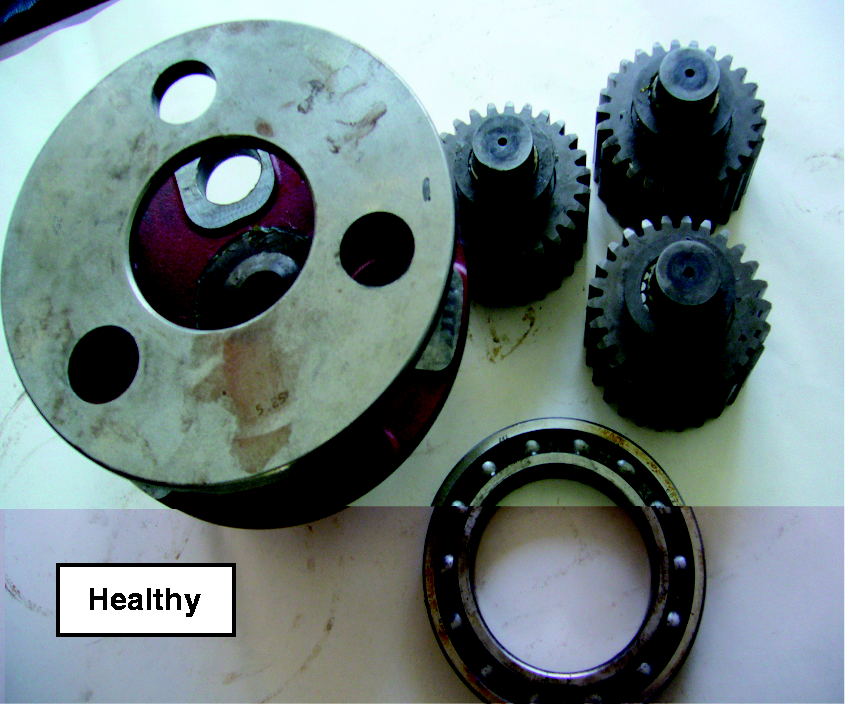
Wind turbine gearbox: Healthy components.
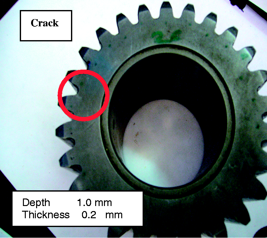
Wind turbine gearbox: Cracked planet gear tooth component.
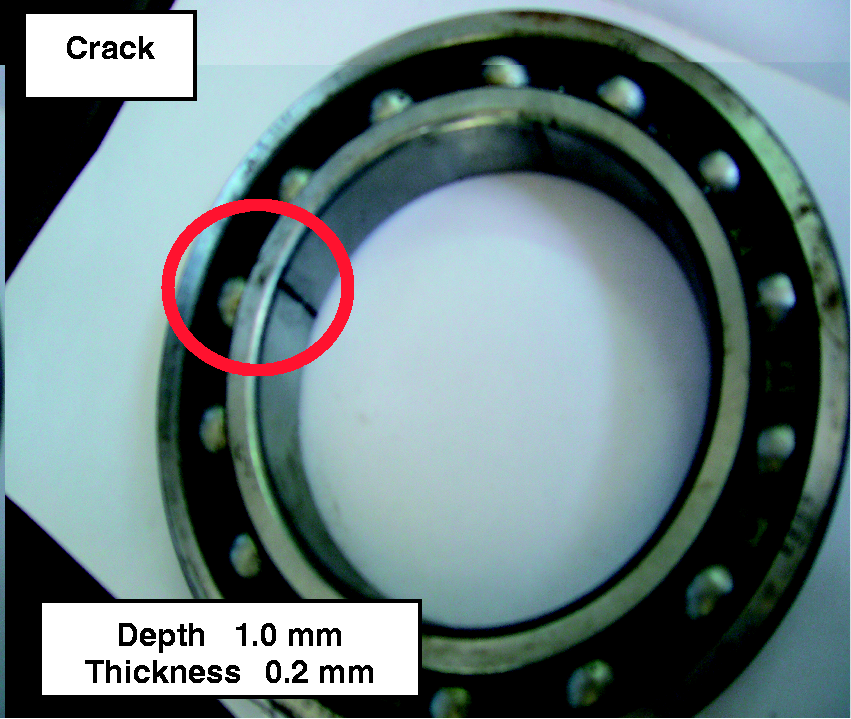
Wind turbine gearbox: Cracked main bearing inner race component.
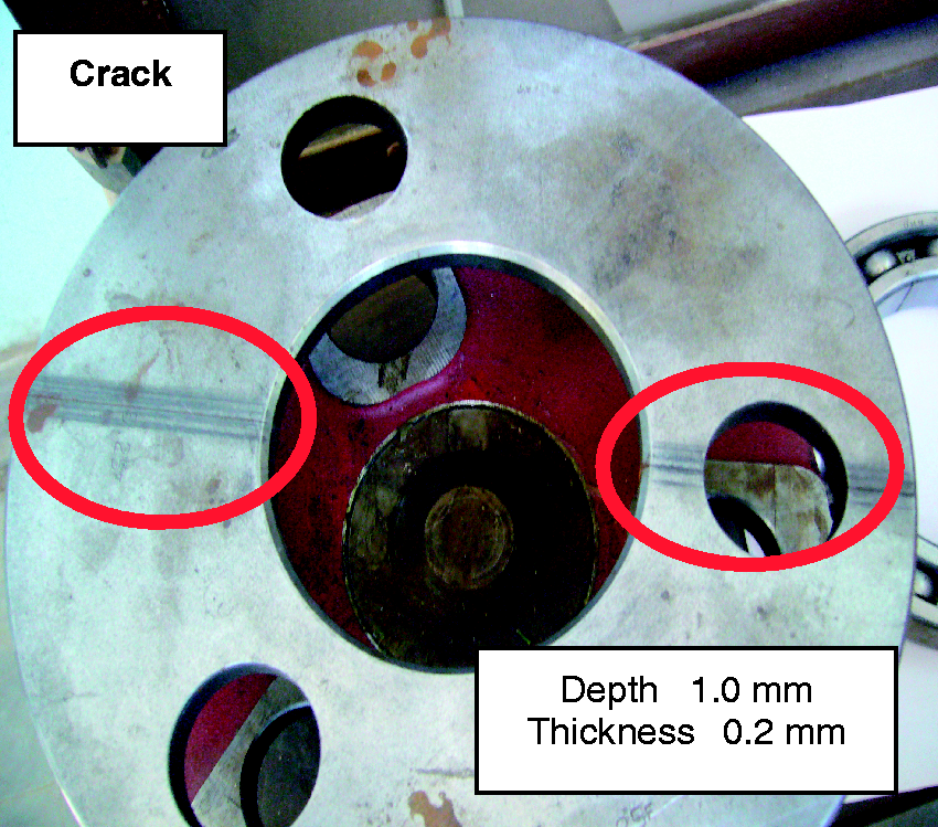
Wind turbine gearbox: Cracked planet gears carrier component.
Results and discussion
Rotational vibration based gearbox fault components diagnosis
Healthy gearbox components
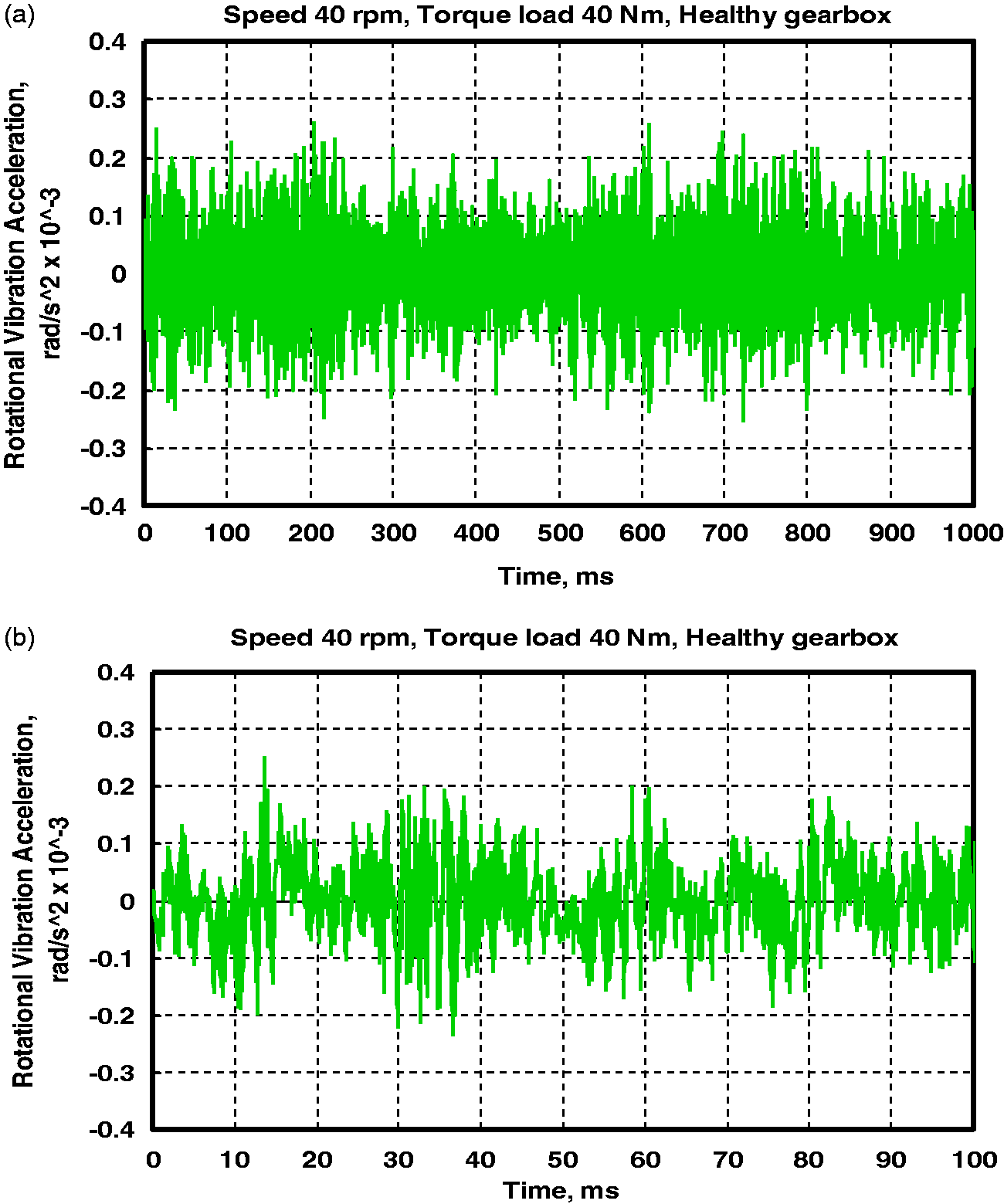
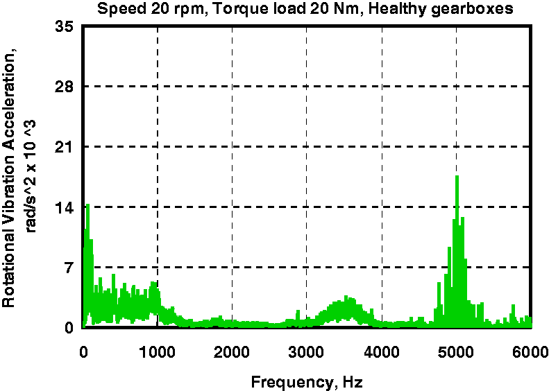
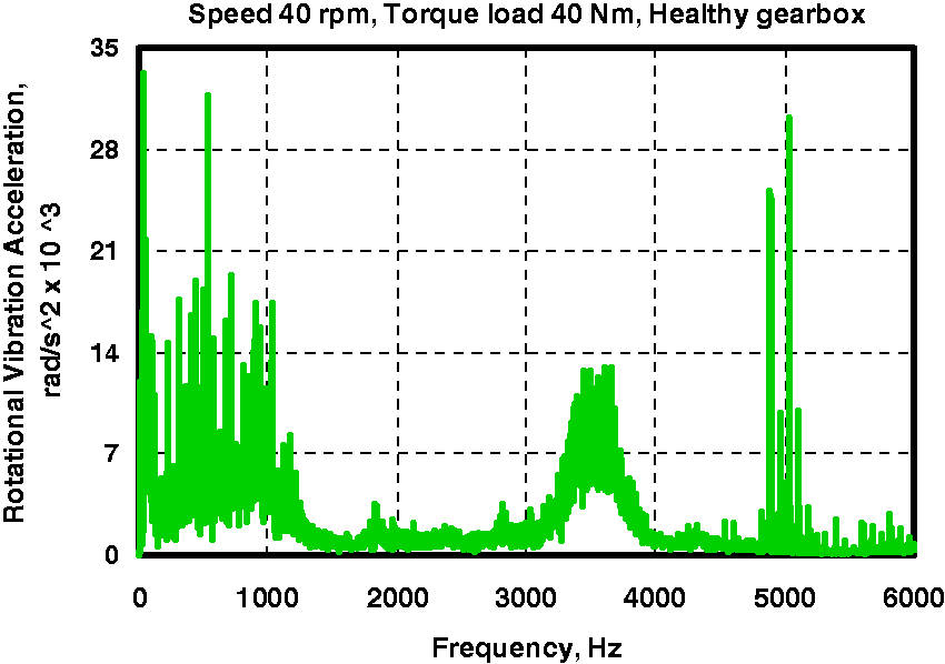
Figures 9 and 12 illustrate the rotational vibration acceleration in terms of time-domain and at speed of 20 r/min with torque load of 20 Nm and at speed of 40 r/min with torque load of 40 Nm respectively for healthy gearbox component measured based on the experimental methodology presented an earlier section. Figures 9(a) and 10(a) show the original signal at 1000 ms, while Figures 9(b) and 10(b) show zoomed signal at 100 ms This is done to display the difference between the defect signal and that for the healthy one in clear way. Figures 11 and 12 show the frequency-domain and at a speed of 20 r/min with torque load of 20 Nm and at speed of 40 r/min with torque load of 40 Nm respectively for healthy gearbox components measured based on the experimental methodology presented in the previous section, where the signals in these figures are normally dominated by tooth meshing harmonics modulation with the rotation of the gear shaft. The signal is normally dominated by tooth meshing harmonics modulation by the rotation of the gear shaft. In most cases, the modulation waveforms are also sinusoids with lower shaft orders, i.e. one time and/or two times the shaft frequency.
Time-domain, rotational vibration acceleration at 20 r/min and 20 Nm: (a) original signal plot at 1000 ms; (b) zoomed signal in plot (a) for 100 ms. Time-domain, rotational vibration acceleration at 40 r/min and 40 Nm: (a) original signal plot at 1000 ms; (b) zoomed signal in plot (a) for 100 ms. Frequency-domain rotational vibration acceleration (20 r/min, 20 Nm). Frequency-domain rotational vibration acceleration (40 r/min, 40 Nm).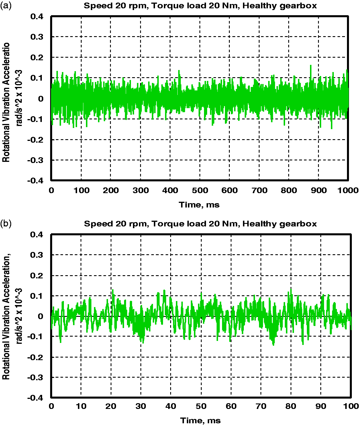
Wind turbine gearbox: Cracked planetary gear tooth results data.
Cracked planet gear tooth component
In cracked planet gear, the crack is simplified and the path of the crack is considered to be a straight line. The intersection angle between the crack and the centerline of the tooth is set at a constant of 45°. The wind turbine planetary gearbox component of planet gear crack defect dimensions is tabulated in Table 2. Figures 13 and 14 illustrate zoomed signal at 100 ms as a sample from the measured results based on the experimental methodology presented in the “Experimental methodology” section for a comparison between healthy and cracked planet gear zoomed signals of the rotational vibration acceleration in terms of time-domain at a speed of 20 r/min with 20 Nm and at 40 r/min with torque load of 40 Nm at testing time of 6.0 h respectively, where the vibration acceleration signals are considered to be stationary waveform. It is observed that the overall time-domain spectrum levels are higher for the cracked planet gear than that of healthy condition, which indicates cracks. When a localized tooth defect occurs, such as crack, the engagement of the cracked tooth will induce an impulsive change with comparatively low energy to the gear mesh signal. This can produce some higher shaft-order modulations and may excite structure resonance.
Zoomed time-domain rotational vibration acceleration for cracked planet gear tooth at 40 r/min and 40 Nm. Zoomed time-domain rotational vibration acceleration for cracked planet gear tooth at 40 r/min and 40 Nm.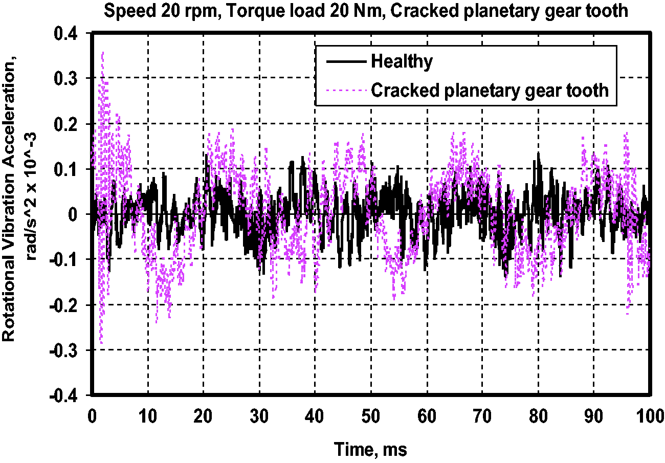
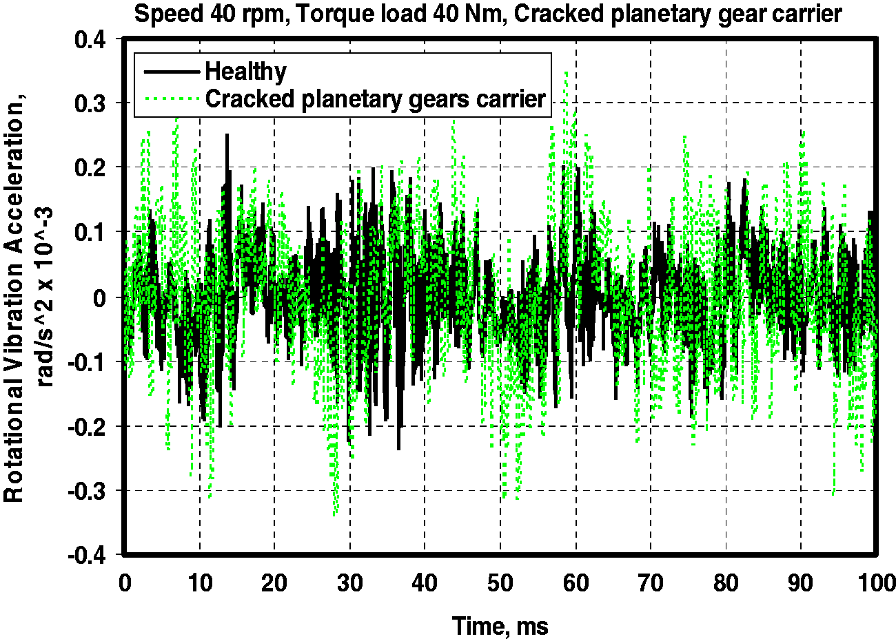
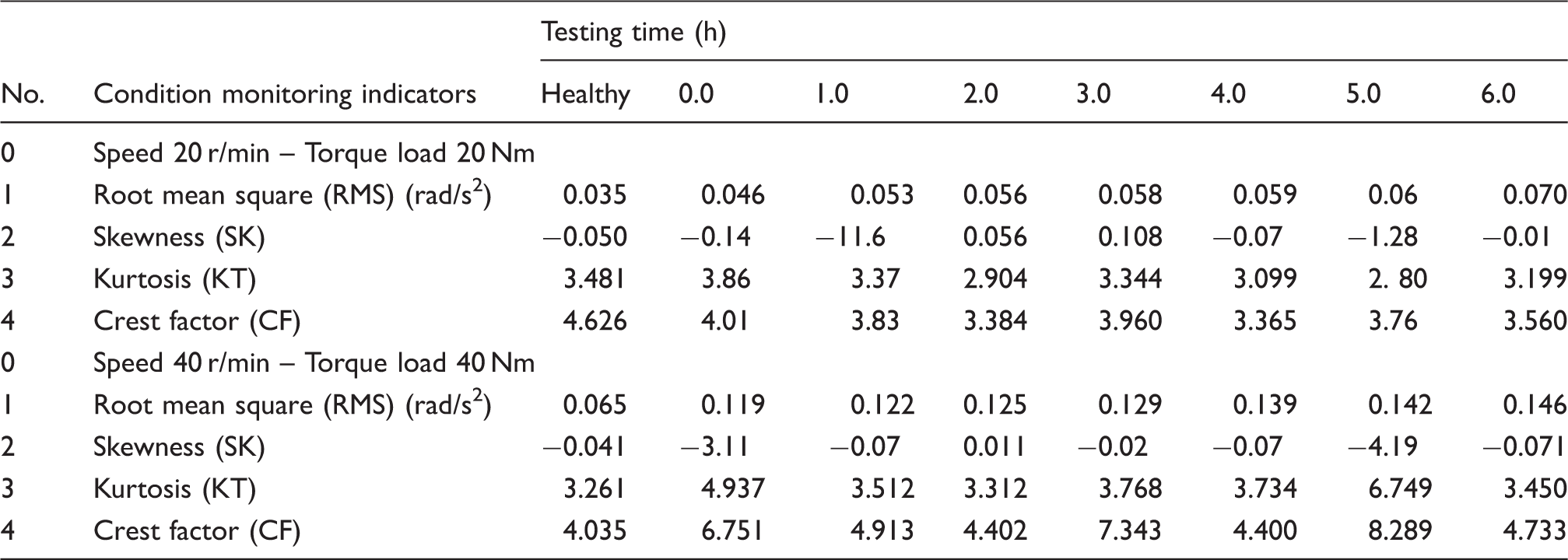
Table 3 tabulates the cracked planet gear condition monitoring indicators values calculated based on equations (1) to (4) of RMS, SK, KT, and CF for the testing time ranging from 0.0 to 6.0 h with the corresponding healthy gearbox at 20 r/min with 20 Nm and at 40 r/min with torque load of 40 Nm. For more accurate observation of these values through the range of the testing time, the RMS value is increased with the increase in the testing time. A magnification is obtained, which is important and possesses diagnostic value as they can be used to define and characterize the critical changes of the gears damage accumulation and evaluation. The values of the remaining indicator parameters are scattering.
Cracked planet gears carrier component
The wind turbine planetary gearbox component of planet gears carrier crack defect dimensions is tabulated in Table 2. Figures 15 and 16 illustrate zoomed signal at 100 ms as a sample from the measured results based on the experimental methodology presented in the “Experimental methodology” section for a comparison between healthy and cracked planet gears carrier zoomed signals of the rotational vibration acceleration in terms of time-domain and at 20 r/min with 20 Nm and at 40 r/min with torque load of 40 Nm at testing time of 6.0 h respectively, where the vibration acceleration signals are considered to be stationary waveform. Based on the time-domain spectra, the overall levels are higher for gear carrier crack than that for healthy condition, which indicates crack. Figures 15 and 16 depict the spectra features of rotational vibration acceleration signals for the two cases under the same load. They exhibit complicated patterns and high density of spectral component, which needs careful examination to find the components of interest and will not appear for a healthy planetary gearbox. The presence of higher levels in the time regions may be due to the gearbox manufacturing and installation errors.
Zoomed time-domain rotational vibration acceleration for cracked planet gears carrier at 40 r/min and 40 Nm. Zoomed time-domain rotational vibration acceleration for cracked planet gears carrier at 40 r/min and 40 Nm.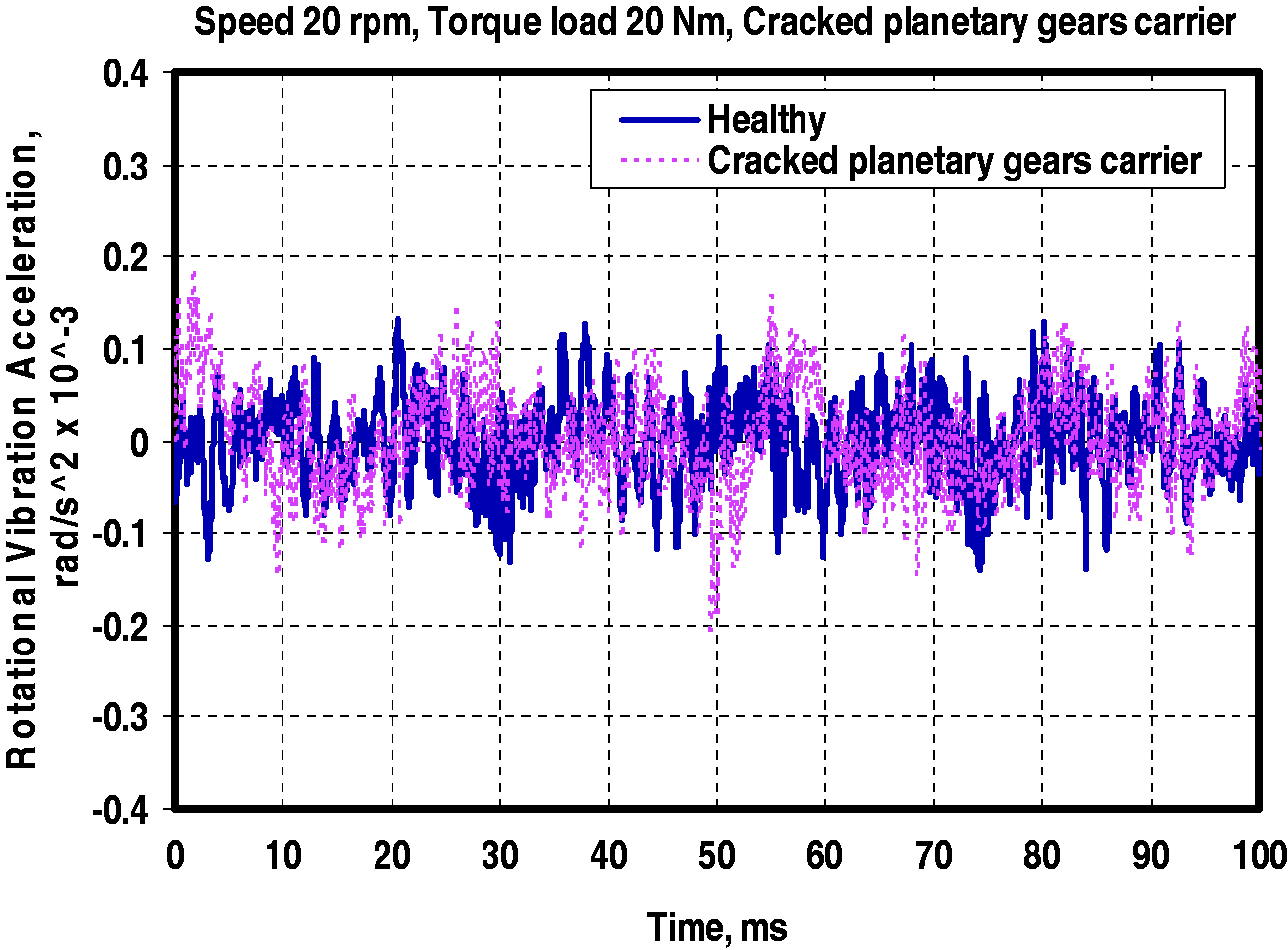

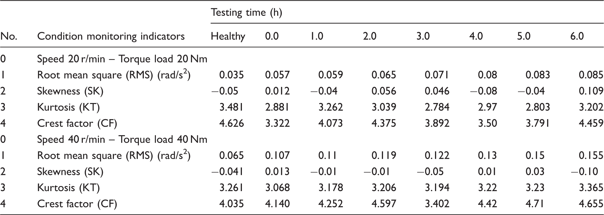
Wind turbine gearbox: Cracked planetary gears carrier results.
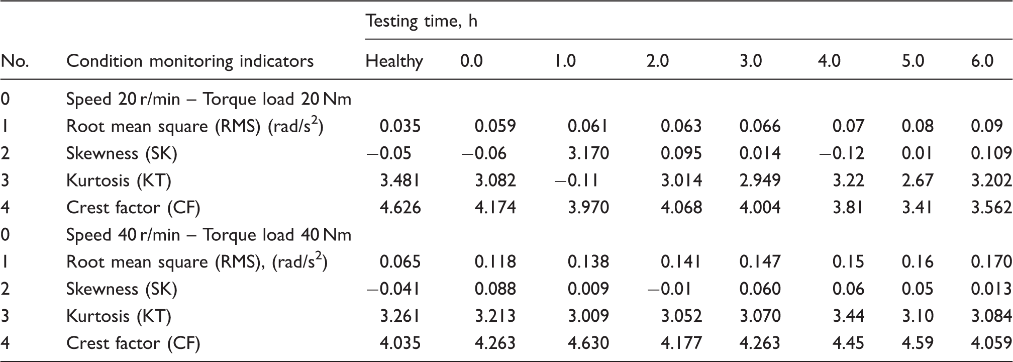
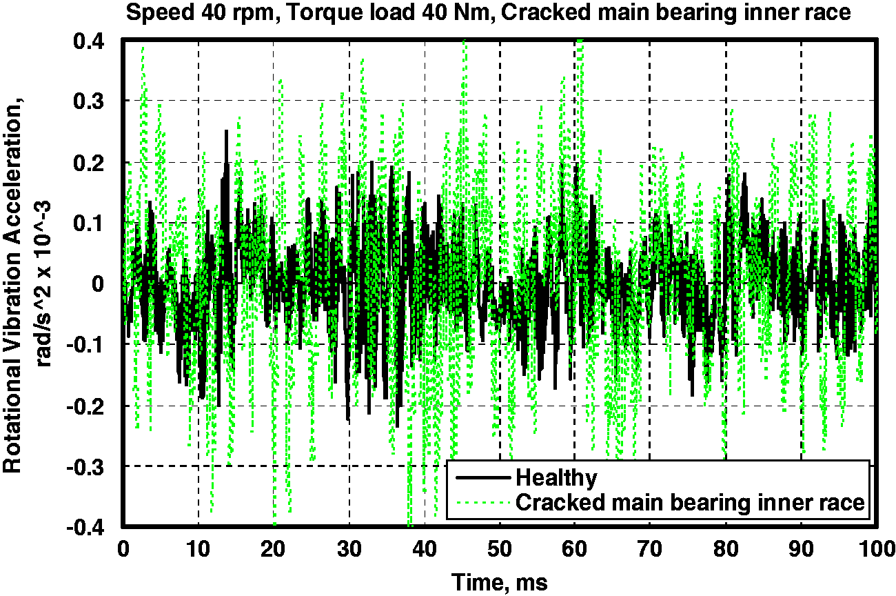
Wind turbine gearbox: Cracked main bearing inner race results.
SK, KT, and CF are global indicators that react to changes in the whole time signal and identify major abnormal behaviors. An increase in the vibration level is generally observed in the case of planet gears carrier such as crack faults without significant change in the spectrum, which will result in the increase in SK, KT, and CF values. They will increase if a periodic signal contains a local increase in level.
Cracked main bearing component
The wind turbine planetary gearbox component of main bearing inner race crack defect dimensions is tabulated in Table 2. Figures 15 and 16 illustrate zoomed signal at 100 ms as a samples from the measured results based on the experimental methodology presents in the “Experimental methodology” section for a comparison between healthy and cracked planet gears carrier zoomed signals of the rotational vibration acceleration in terms of time-domain at a speed of 20 r/min with 20 Nm and at speed of 40 r/min with torque load of 40 Nm at testing time of 6.0 h respectively, where the vibration acceleration signals are considered to be stationary waveform. Based on time-domain spectra, the overall levels are higher for gear carrier crack than that for healthy condition, which indicates crack. From the spectra in Figures 17 and 18, it can be seen that the characteristic of bearing fault and its harmonics may be interfered by the complex gearbox signal components. Some time-domain levels may be greatly reduced, which is not conductive to bearing fault diagnosis. Therefore, only the time-domain with high level values will be selected for bearing fault diagnosis.
Zoomed time-domain rotational vibration acceleration for cracked main bearing inner race at 40 r/min and 40 Nm. Zoomed Time-domain rotational vibration acceleration for cracked main bearing inner race at 40 r/min and 40 Nm.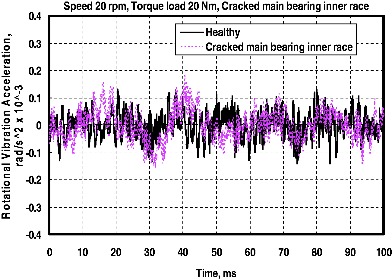
In order to suppress the interference from gear vibration, time synchronous technology is used to extract the residual signal, which mainly contains the vibration produced by bearing fault. Firstly, the vibration signal is resampled according to the rotational information, which ensures the signal is sampled with equal shaft degree. Then, this resampled signal minus the equal length of time synchronous averaging signal will result in the residual signal. Next, the post processing is based on the residual signal.
Table 5 tabulates the planet gears carrier crack condition monitoring indicators values computed based on equations (1) to (4) for the testing time ranging from 0.0 to 6.0 h with the corresponding healthy gearbox at 20 r/min with 20 Nm and at 40 r/min with torque load of 40 Nm. Basically, the RMS of the rotational vibration acceleration signal is more closely related to gearbox rotational vibration acceleration and mechanical interaction. In addition to RMS, three physical meshing behavior-related condition indicators are also seen: SK, KT, and CF. Then the rotational acceleration signal condition indicators were calculated on the time-domain signals. Three condition indicators as introduced in section “Condition monitoring indicators” were computed using the time-domain vibration acceleration signals.
In summary, it can be seen that for axial vibration accelerometer mounted on the bearing housing, the RMS and KT show good fault detection potential. SK and CF of the axial accelerometers work in most cases but are not stable. The vibration signals are highly affected by the background noise or mechanical resonance, making their performance unstable.
Gearbox components defects (faults) severity assessment
From the previous discussion, the condition monitoring indicators of RMS, skewness SK, KT, and CF have been generating intensive interest. They have nearly similar trend, where the RMS value is found to be a better indicator when compared to other indicators. However, the RMS values of rotational vibration acceleration are used to evaluate the wind turbine gearbox components faults severity assessment. Figure 19 depicts severity assessment which has been achieved by the development of the experimental technique at 20 r/min and torque load of 20 Nm and speed of 40 r/min and torque load of 40 Nm at testing time of 6.0 h. The figure indicates that the cracked main bearing posses the highest RMS value followed by cracked planet gears carrier with cracked planet gear has the least RMS value.
RMS values for nominal vibration acceleration.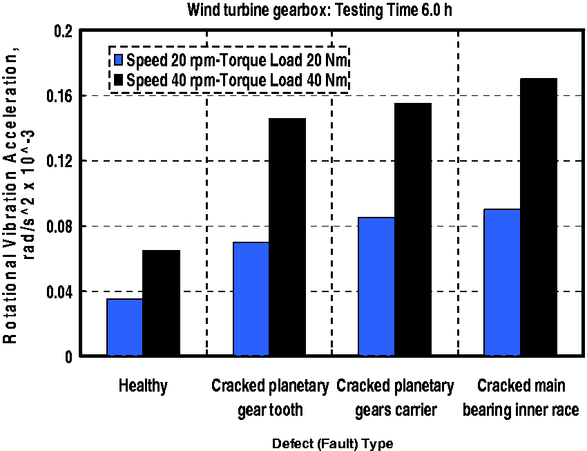
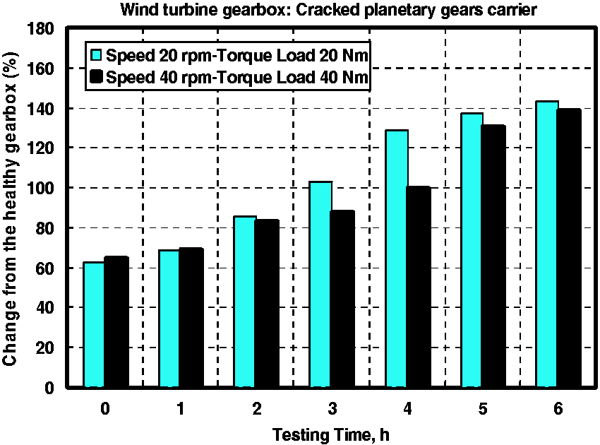
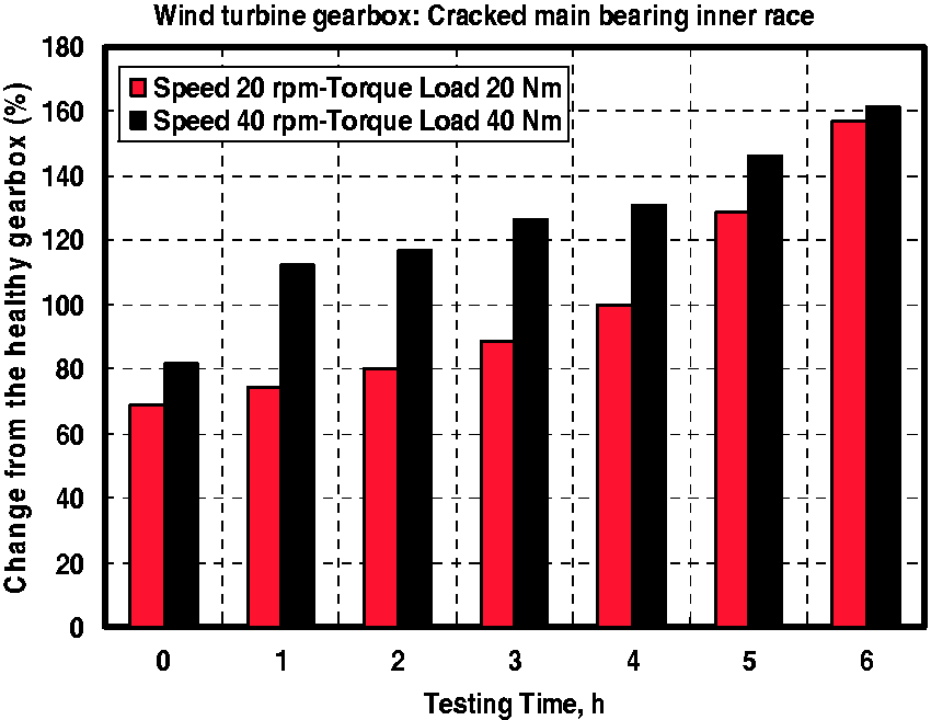
On the other hand, in order to establish both the sensitivity and robustness of the gearbox condition indicator Figures 20 to 22 tabulate the percentage of the fault's rotational vibration acceleration RMS change from the healthy gearbox level from that of the healthy gearbox (CFHL) at 20 r/min and torque load of 20 Nm, and at 40 r/min and torque load of 40 Nm at the testing time of 6.0 h based on equation (5) with respect to cracked planet gear, cracked planet gears carrier, and cracked main bearing, respectively. Generally speaking, the CFHL computed for the faults considered in this work at speed of 40 r/min and torque load of 40 Nm is greater that of 20 r/min and torque load of 20 Nm. The use of CFHL, % has shown that the fault on wind turbine planetary gearbox can be detected at its early stages, and symptoms of fault on vibration is not primarily caused by the reduction components stiffness (which is the case for the detection of a localized fault), but mainly due to the deviations in component shape from the true component shape, where the deviations in component shape causes the original vibration and consequently causes the onset of the fault, whatever be the value of stiffness.
Percentage change from healthy gearbox of cracked planetary gear tooth. Percentage change from healthy gearbox of cracked planetary gears carrier. Percentage change from healthy gearbox of cracked main bearing inner race.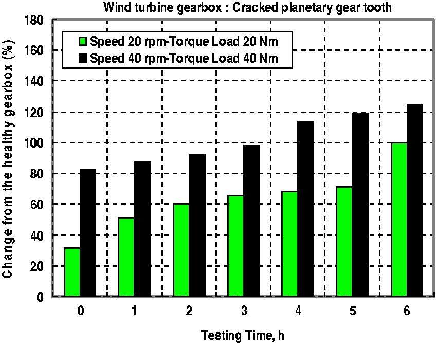
Conclusions
In this paper, a new measurement technique-based planetary gearbox components fault diagnostic methodology was presented. The presented method was accomplished through the real-time signals and condition indicators to extract diagnostic features for planetary gearbox diagnosis. First, the accelerometer signal is band pass analyzed so as to retain the information related to the gear conditions. Then, the time-domain signal is computed to obtain the periodically repeated waveform. The presented method was validated using data collected from seeded fault tests conducted on a planetary gearbox test rig in a laboratory.
In stationary vibration waveform feature, the periodical impulses caused by the wind turbine gearbox faults appear in the time-domain signal as the fault level increases. This carries diagnostic information, which is of great importance for extracting features of the fault. Furthermore, experimental results are revealed where the wind turbine planetary gearbox components defects (faults) can be identified.
In order to extract the impulse feature of faulty gearbox components, rotational vibration acceleration signals are used to analyze the vibration signals of both healthy and faulty gearbox. The wind turbine gearbox components considered are planet gear, planet gear carrier, and main bearing. Furthermore, the condition monitoring indicators of the RMS, SK, KT, and CF reflect the rotational vibration responses of the gearbox. The results look promising, where the RMS value analysis could be a good indicator when compared with the other indicators considered for early detection and characterization of faults. Moreover, multihour tests were conducted and recordings and were acquired using rotational vibration monitoring.
From this investigation, the gearbox components faults severity assessment has indicated that the cracked main bearing possess the highest RMS value followed by cracked planet gears carrier with cracked planet gear having the least RMS value. This can help to identify which type of defect can be considered first. Moreover, the symptoms of fault on vibration is not primarily caused by the reduction components stiffness (which is the case for the detection of a localized fault), but mainly due to the deviations in component shape from the true component shape.
In this paper, a gearbox condition indicator was investigated in order to determine its sensitivity to faults under variable operational conditions. It was demonstrated that the gearbox condition indicators are able to discriminate between proper and improper fault conditions. However, it cannot be used to follow the progression of the fault and is sensitive to variations in the operational conditions. Further investigation is required to improve the ability of the gearbox condition indicators. Furthermore, future work will include the investigation of multiple localized defects and extension of the theoretical model in three dimensions to simulate helical gears.
The use of percentage of the faults' rotational vibration acceleration RMS change from the healthy gearbox level from that of healthy gearbox (CFHL), % which has shown that the fault on wind turbine planetary gearbox can be detected at its early stages, and symptoms of fault on vibration is not primarily caused by the reduction components stiffness (which is the case for the detection of a localized fault), but mainly due to the deviations in component shape from the true component shape.
Footnotes
Declaration of conflicting interests
The author(s) declared no potential conflicts of interest with respect to the research, authorship, and/or publication of this article.
Funding
The author(s) received no financial support for the research, authorship, and/or publication of this article.