
Abstract
Crest-fixed trapezoidal cold-formed steel (CFS) cladding systems, widely used in Australia and neighbouring countries, are prone to localized pull-through failures around screw fasteners under high wind uplift/suction loading. Unlike corrugated cladding, which exhibits localized dimpling-type failures, and trapezoidal cladding with wide pans, which often fails through transverse splitting, trapezoidal cladding with closely spaced ribs can experience either localized dimpling or splitting-type pull-through failures. These failures result from significant stress concentrations beneath screw heads and the limited ductility of high-strength steel, posing challenges for accurate prediction through analytical methods. As a result, the design of crest-fixed trapezoidal cladding with closely spaced ribs relies on experimental testing, with few design guidelines available to address these specific failure modes and pull-through capacity. This study proposes and calibrates a ductile damage material model specifically for very thin, high-strength cold-formed steel, enabling accurate simulation of damage initiation, progression, and fracture. The model was implemented in an advanced finite element framework capable of reproducing both localized dimpling and transverse splitting pull-through failures under static wind uplift loading. Validation against experimental data showed excellent accuracy with a low coefficient of variation of 0.02, while an extensive parametric study identified the effects of key parameters such as crest height that increased the capacity by up to 90%. The findings improve the understanding of pull-through behaviour and lead to practical design recommendations for optimising crest-fixed trapezoidal cladding systems. The proposed equation predicted the capacities within 5%, demonstrating strong potential for design-code adoption.
Keywords
Introduction
In Australia, profiled steel roof claddings, typically made of 0.42 mm or 0.48 mm high-strength G550 steel with minimum yield strength of 550 MPa, are widely used in the building industry. They are always crest-fixed with screw fasteners to timber or steel purlins/battens. While valley-fixing offers higher wind uplift strength, crest-fixing is preferred to prevent water leakage. The most common cladding profiles include corrugated claddings with alternate crest-fixing (Figure 1(a)), trapezoidal claddings with wide pans with every crest fixing (Figure 1(b)), and trapezoidal claddings with closely spaced ribs with alternate crest-fixing (Figure 1(c)). Among them, trapezoidal cladding with closely spaced ribs are particularly popular due to its superior spanning capacity and cost efficiency. However, under high wind uplift or suction loading, crest-fixed CFS claddings are prone to localized pull-through failures around the screw heads. The failure modes vary depending on the cladding profile. Corrugated claddings fail through localized dimpling (Lovisa et al., 2013; Pieper and Mahendran, 2022), whereas trapezoidal claddings with wide pans are more likely to fail through splitting-type pull-through (Pieper and Mahendran, 2022). In contrast, trapezoidal claddings with closely spaced ribs may experience either localized dimpling or splitting-type pull-through failures (Mahaarachchi, 2003; Mahendran, 1994; Pieper, 2022), as illustrated in Figure 2(a) and (b), respectively. Crest-fixed steel cladding profiles: (a) corrugated cladding (b) trapezoidal cladding with wide pans and (c) trapezoidal cladding with closely spaced ribs. Pull-through failure modes of trapezoidal cladding with closely spaced ribs (Mahaarachchi and Mahendran, 2009b; Pieper and Mahendran, 2022): (a) dimpling type failure and (b) splitting type failure.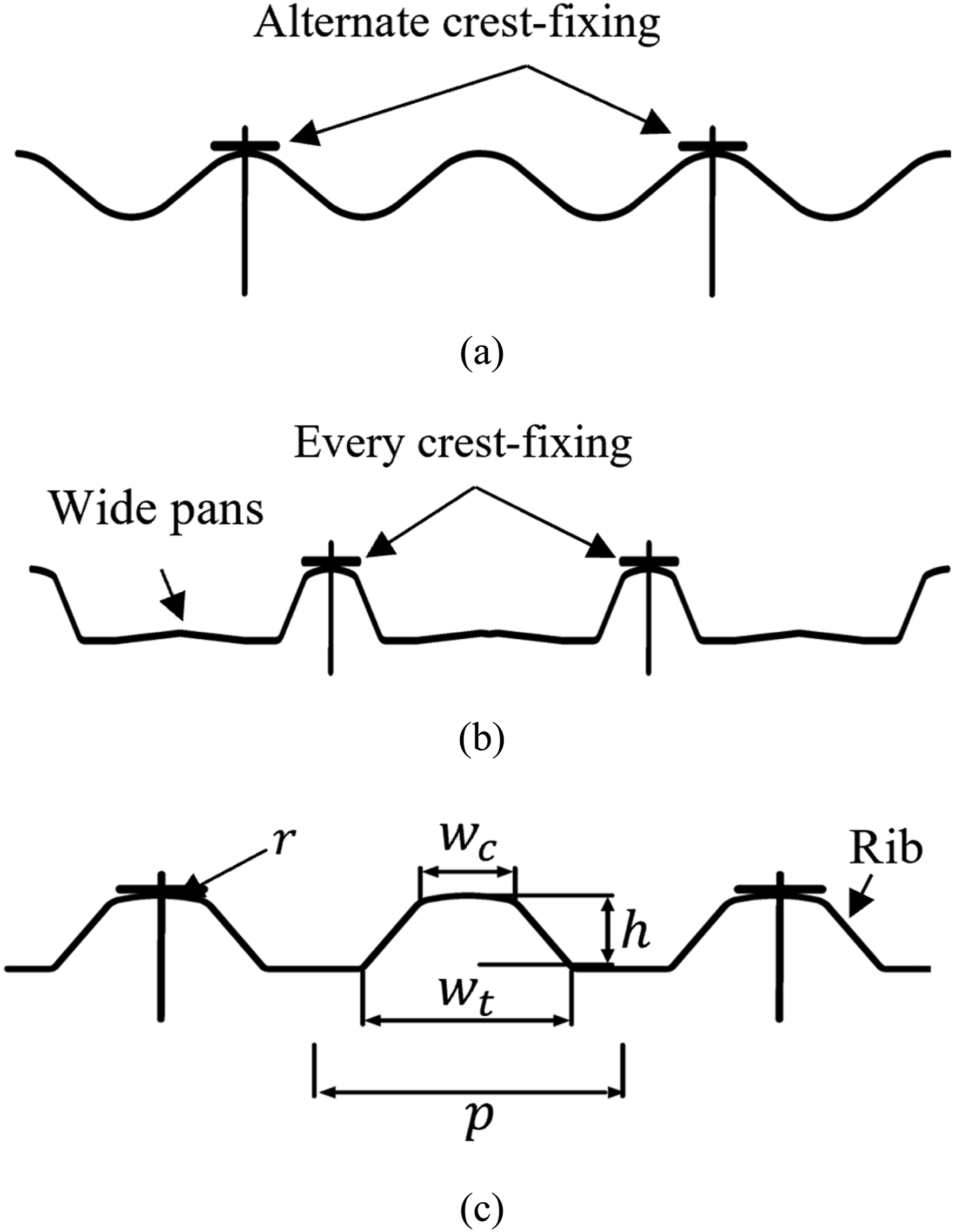
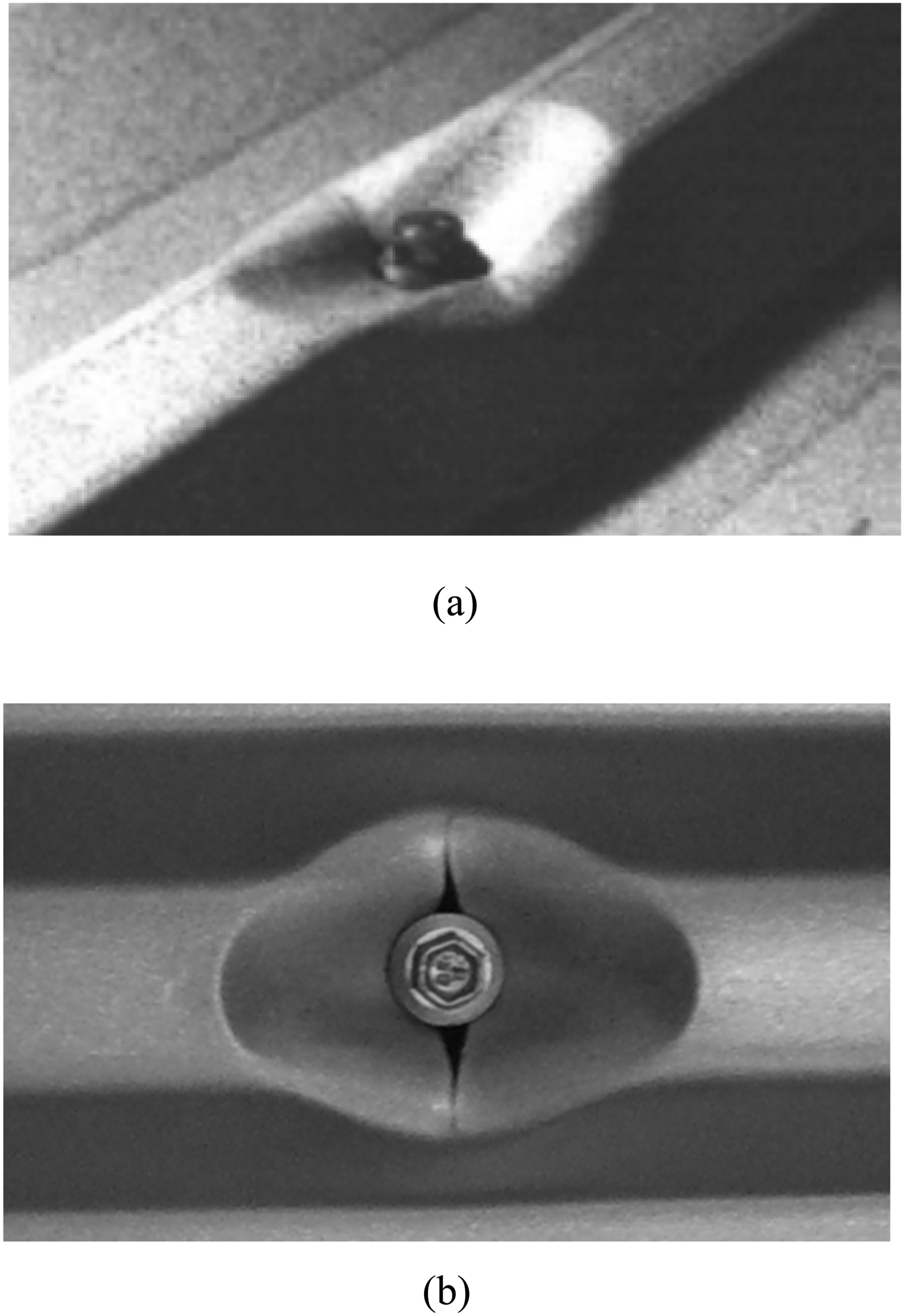
Splitting-type pull-through failures are particularly severe because they can lead to the complete loss of roof or wall cladding as the sheet pulls over the screw head. Conversely, localized dimpling-type failures often result in fatigue cracking under sustained cyclic wind loading, which can eventually cause the detachment of the entire cladding. Both failure modes pose significant risks to structural integrity, with severe cases potentially resulting in total structural collapse or generating windborne debris that damages nearby structures (Morgan and Beck, 1976). Despite the critical role of roof and wall cladding systems in ensuring structural performance, their design often receives lower priority. This oversight leaves such systems susceptible to these failure modes. Furthermore, no existing design capacity equations account for localized dimpling or splitting-type failures in crest-fixed trapezoidal claddings with closely spaced ribs. This underscores the need for reliable numerical models and design equations to ensure the safety and efficiency of these widely used cladding systems under extreme wind conditions.
Past investigations by Pieper and Mahendran (2022), Mahaarachchi and Mahendran (2009a, 2009b), and Xu and Reardon (1993) have experimentally studied the behaviour of crest-fixed trapezoidal cladding with closely spaced ribs under both static and cyclic wind uplift loading. They examined the pull-through capacities of trapezoidal cladding with closely spaced ribs through large-scale and small-scale tests. Pieper and Mahendran (2022) further extended their study to elevated temperatures. Additionally, Xu and Reardon (1993) investigated the pull-through capacity of trapezoidal cladding by replacing self-drilling screws with cyclonic washers and found increase in the pull through capacity. Mahaarachchi and Mahendran (2009b) also investigated the pull-through failure of trapezoidal cladding with closely spaced ribs. However, their study assumed that dimpling-type failure was the sole failure mode for such claddings. Although Mahaarachchi and Mahendran 2009a) developed a strain criterion to predict the splitting-type failure, this criterion was only developed for trapezoidal claddings with wide pans. Consequently, their findings do not fully address the complex failure mechanisms of claddings with closely spaced ribs, which exhibit both dimpling and splitting-type pull-through failures.
Additionally, the limited number of results from these studies and limitations in the numerical models mean that the proposed design equations do not account for important geometric and material parameters that significantly influence the pull-through capacity and failure modes. Hence the Australian CFS Standard AS/NZS 4600 (Standards Australia, 2018) lacks a design equation for the pull-through capacity of crest-fixed trapezoidal roof claddings. This absence has led to reliance on laboratory tests for designing thin steel cladding systems, hindering innovation and progress in the steel cladding industry.
Although previous studies have improved the understanding of pull-through behaviour in crest-fixed CFS claddings, they have largely depended on experimental tests and numerical models that were empirical or specific to a single failure mode, typically able to simulate only dimpling-type behaviour. No prior work has implemented a damage-based material model (material model beyond the ultimate point) capable of reproducing both splitting- and dimpling-type failures within one consistent modelling framework. As a result, existing numerical approaches remain restricted to specific cladding geometries and are predominantly valid only for dimpling-type failures. Likewise, earlier research has not produced a generalised damage-based numerical model that can accurately reproduce the full fastener load–deflection response while also capturing both splitting and dimpling failures in trapezoidal claddings, nor one that enables the development of a rational design equation applicable across a wide range of geometric and material conditions. Achieving this capability is essential for optimising cladding profiles and, importantly, for producing an accurate and reliable design equation suitable for inclusion in AS/NZS 4600.
To address these gaps, the development of an advanced numerical model capable of predicting both dimpling and splitting-type pull-through failures in trapezoidal claddings with closely spaced ribs is crucial. Such a model would enable a detailed investigation of cladding behaviour across various geometric and material conditions, facilitating accurate prediction of pull-through capacity and advancing design practices. Therefore, this study develops an advanced finite element model for crest-fixed trapezoidal steel cladding with closely spaced ribs, incorporating a newly proposed and calibrated ductile damage material model for very thin, high-strength cold-formed steel. The model accurately predicts both dimpling- and splitting-type pull-through failures by simulating damage initiation, evolution, and fracture, and is validated against experimental results from the literature. An extensive parametric study with over 400 FE simulations is conducted, considering key factors such as geometric parameters, material properties, cladding span, and screw head diameter. Based on the results, a suitable design equation is proposed to predict the pull-through capacity of crest-fixed trapezoidal cladding with closely spaced ribs. It incorporates variations in geometry, material, and span, offering a practical and reliable tool for optimizing roof cladding system design.
Modelling of trapezoidal cladding subject to localized failures
The numerical model of crest-fixed trapezoidal cladding with closely spaced ribs and alternate crest-fixing was developed using Abaqus/CAE and validated against existing experimental data. The developed finite element (FE) model represents the full width of a single sheet (768 mm) in a two-span configuration (2 × 900 mm) (Figure 3), simulating the behaviour of multi-span roof cladding systems under wind uplift/suction loading (Mahaarachchi and Mahendran, 2009b). The geometry and fastener arrangement of the 0.42 mm thick trapezoidal cladding are shown in Figure 3, providing a good representation of the cladding system. The trapezoidal cladding with closely spaced ribs shown in Figure 1(c) features a crest height FE model of trapezoidal cladding with closely spaced ribs.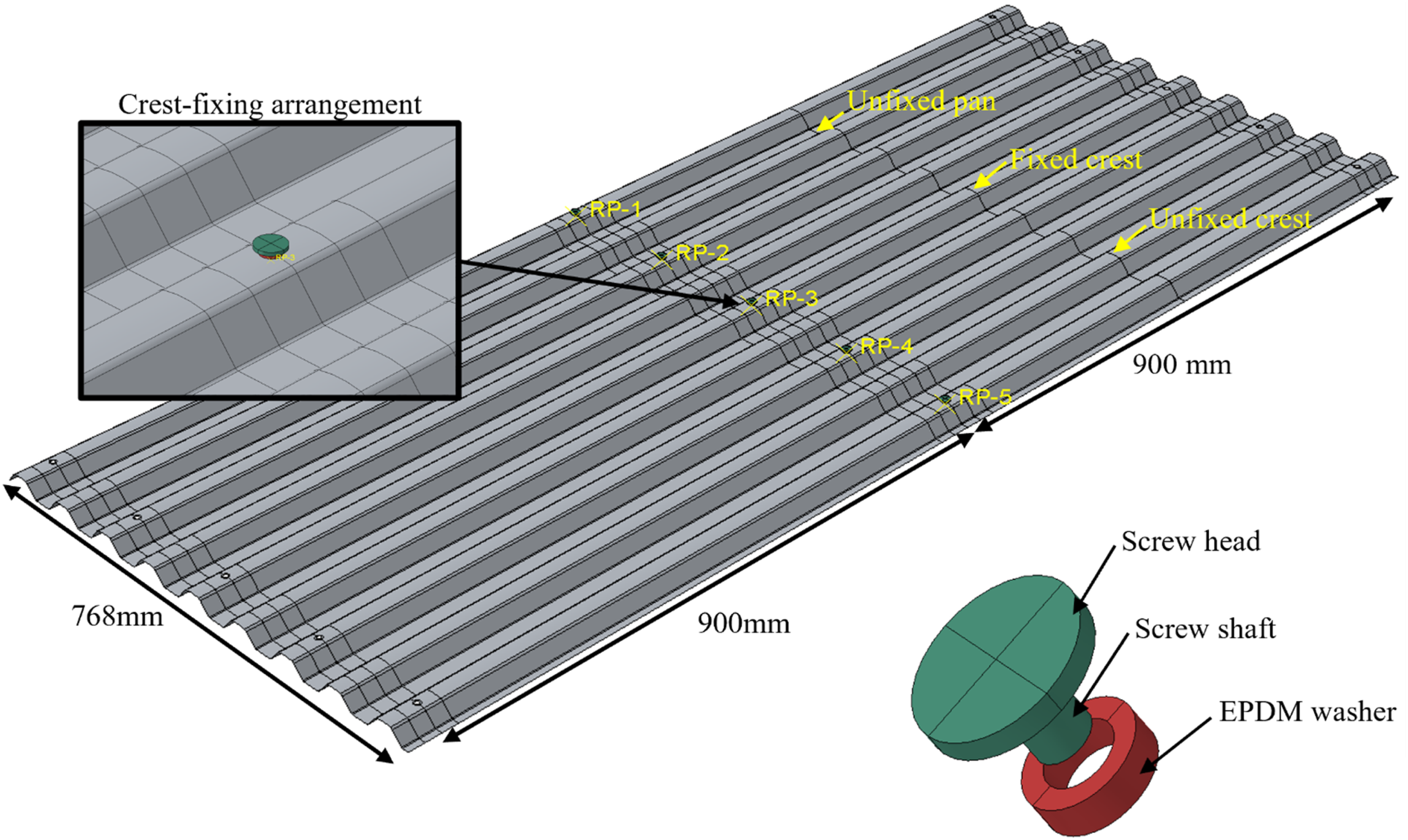
Further, crest-fixing details were incorporated into the model to replicate the actual conditions. A neoprene washer with a diameter of 10 mm and a thickness of 3 mm, along with a 14.5 mm diameter screw head and a portion of screw shaft with 6 mm diameter were incorporated to represent the typical M6 self-drilling screw fastener arrangement used in practice. These elements enable the model to capture localized deformation and stress concentration around the screw heads, which are key factors influencing pull-through failure behaviour.
Material modelling
Commonly used self-drilling screw types include M6-11 × 50, M12-14 × 35, and M12-11 × 50, selected based on the material and thickness of battens or purlins. These screws are typically made from carbon steel, with mechanical properties governed by AS 4291.1 (Standards Australia, 2015). According to both the manufacturer’s specifications and AS 4291.1 (Standards Australia, 2015), the minimum yield strength of these screws is 600 MPa. In this study, self-drilling screws were modelled as elastic-perfectly plastic materials, with a yield strength of 690 MPa and a Young’s modulus of 200 GPa.
The behaviour of neoprene washers, used alongside these screws, was investigated through compression tests conducted by Lovisa (2015). Her study compared experimental results with numerical simulations in Abaqus/CAE and identified the Ogden model, with a Poisson’s ratio of 0.475, as the most accurate for representing neoprene washers. The material constants (D, α) and shear modulus (μ) for the Ogden model, derived from experimental data, were determined to be 0.037, 0.01, and 2.7 MPa, respectively.
In addition, a ductile damage material model was developed to simulate the splitting-type failure in trapezoidal cladding with closely spaced ribs. This model incorporates linear elastic behaviour, damage initiation, and damage evolution to accurately capture the complex failure mechanisms under wind uplift loading.
Ductile damage modelling of G550 cold-formed steel
Engineering stress–strain response and true stress–strain conversion
The mechanical behaviour of high-strength CFS such as G550 can be divided into several distinct phases, as illustrated in Figure 4. Initially, the material shows a linear elastic response from point a to the yield point b. Beyond yielding, strain hardening occurs from b to c, followed by fracture initiation at point c, which marks a steep decline in stress-carrying capacity until complete fracture at d. The dashed line represents the idealised response in the absence of damage, showing the behaviour without fracture. Stress-strain curve with progressive damage degradation (Abaqus, 2012).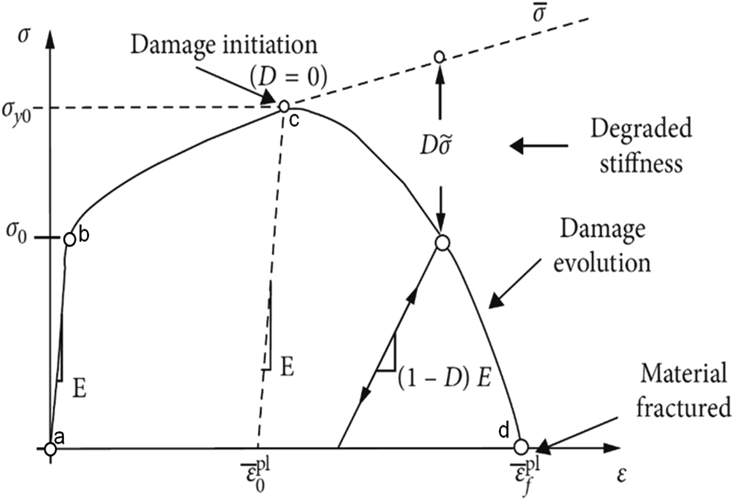
To model the elastic behaviour of G550 CFS cladding, the Young’s modulus


Since deformation in the post-necking region is no longer uniform due to strain localization, it is essential to use an appropriate true post-necking stress-strain curve to accurately represent the actual behaviour of steel. To achieve this, this study used a combined linear and power law proposed by Ling Yun (1996) to describe the true stress-strain relationship after necking, as shown in equation (3).

The parameters in equation (3) are defined as follows: True stress-strain curve developed for 0.42 mm thick G550 steel.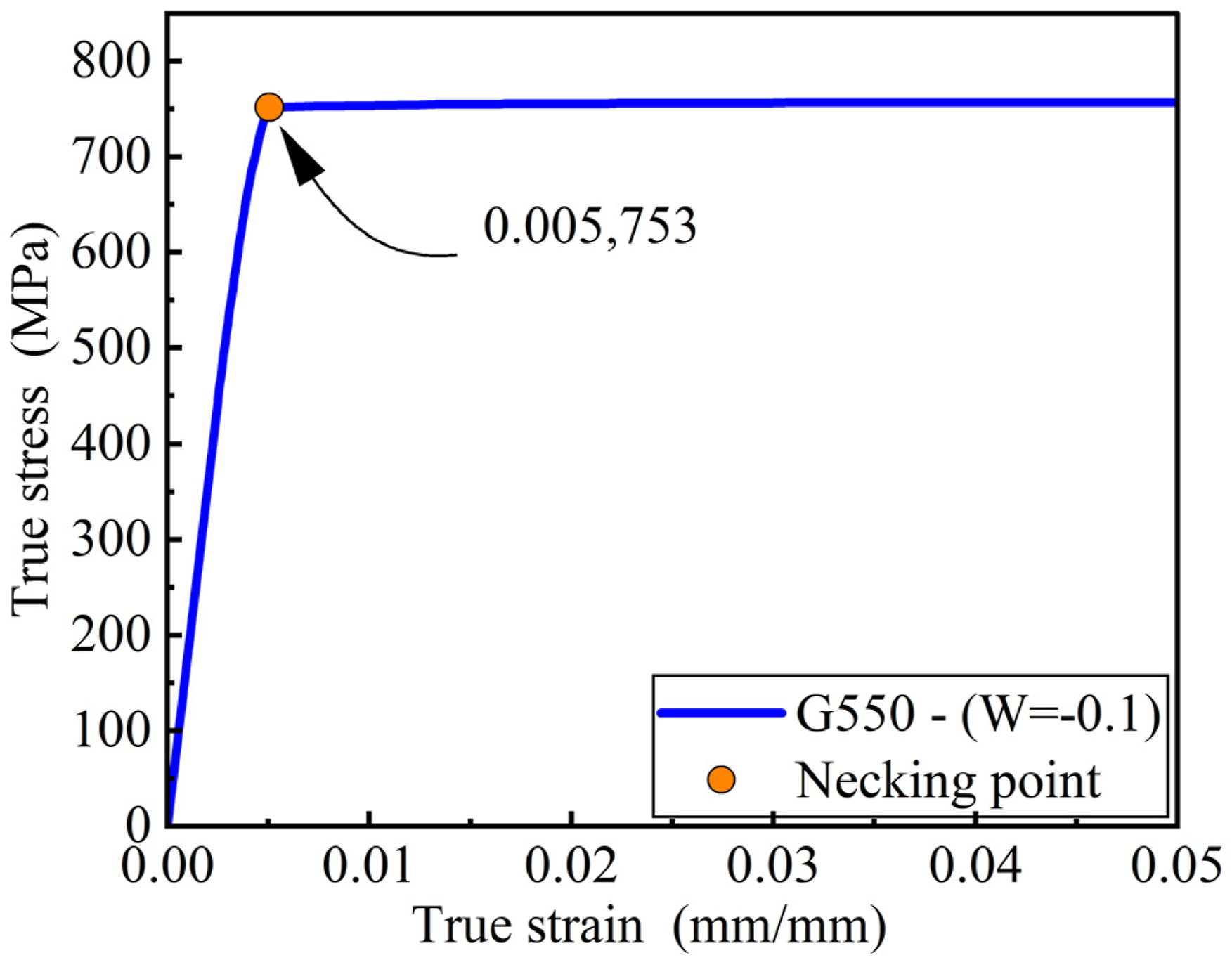
Damage initiation and evolution
To represent the phase from the onset of necking to fracture, this study employs a ductile damage model (Abaqus, 2012) within Abaqus/CAE 2023 to simulate the splitting failure in trapezoidal cladding with closely spaced ribs under wind suction loading. By incorporating the parameters such as damage initiation, evolution, and fracture, the model can accurately predict the onset and propagation of splitting failure in the cladding. First to define the damage initiation criterion, it was assumed that damage initiation is controlled by plastic strains and hydrostatic stresses, like fracture initiation in the Void Growth Model (VGM). The equivalent plastic strain (PEEQ) at damage initiation Damage initiation PEEQ versus stress triaxiality.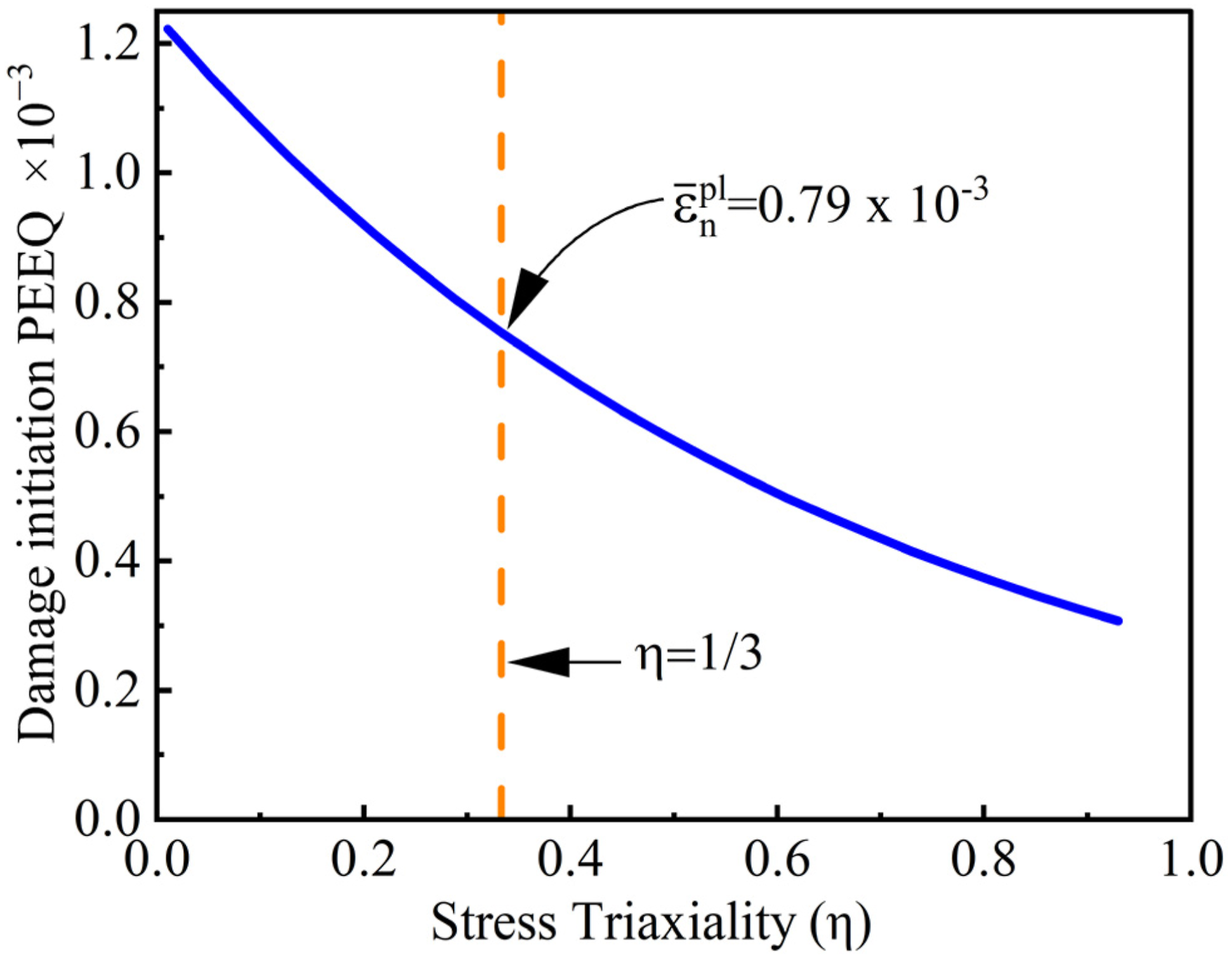


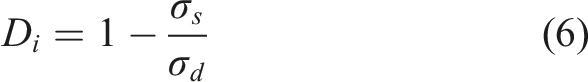
After the damage initiation criterion is satisfied, the material stiffness degradation is modelled using a scalar damage variable Relationship between 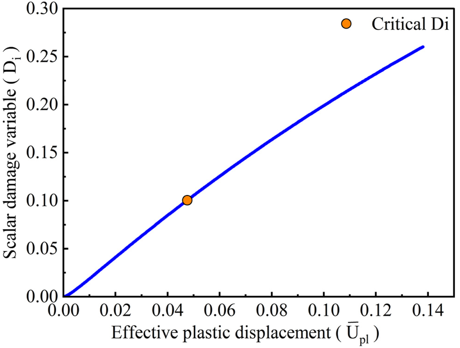


To evaluate the proposed damage model, tensile coupon tests on CFS were simulated using the ductile damage model in Abaqus/CAE 2023. The undamaged stress-strain curves were incorporated to define the material’s plasticity. The damage initiation criteria (Figure 6) and damage evolution laws (Figure 7) were applied as part of the ductile damage modelling framework. Furthermore, the critical damage variables depicted in Figure 7 were included in the simulations to account for tensile coupon fracture. The simulations were performed using quasi-static analyses with the explicit dynamic solver in Abaqus. Figure 8 compares the engineering stress-strain curves obtained from the experiments and FE analysis, demonstrating a close match. This validates the accuracy and effectiveness of the ductile damage model implemented in the simulations. Comparison between experimental coupon test and FE simulation result with the damage model.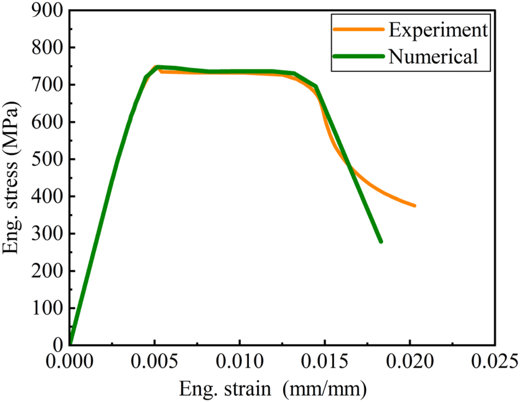
Boundary conditions and loading
Figure 9 illustrates the boundary conditions and interactions used to in a single sheet cladding assembly, accurately replicating the experimental conditions. The transverse edges of the sheeting near the end supports, as well as the longitudinal edges of the FE model, were left unrestrained since the cladding assembly is only secured against wind uplift by the screw heads. Experimental observations revealed that nodes around the fastener holes tend to move laterally under wind loading. However, this lateral displacement is counteracted by the presence of the screw shaft, which resists lateral pressure from wind uplift loading. To replicate this behaviour in the FE model, the X and Z translations of nodes adjacent to the screw holes were constrained as shown in Figure 9, simulating the restraining effect of the screw shaft. Additionally, the bottom layer of nodes of the short screw shaft was coupled to a reference point, which was then constrained against all three translations. This approach effectively simulates the fixed support condition at the base of the screw provided by the connection to the battens/purlins. Boundary conditions of trapezoidal cladding with closely spaced ribs.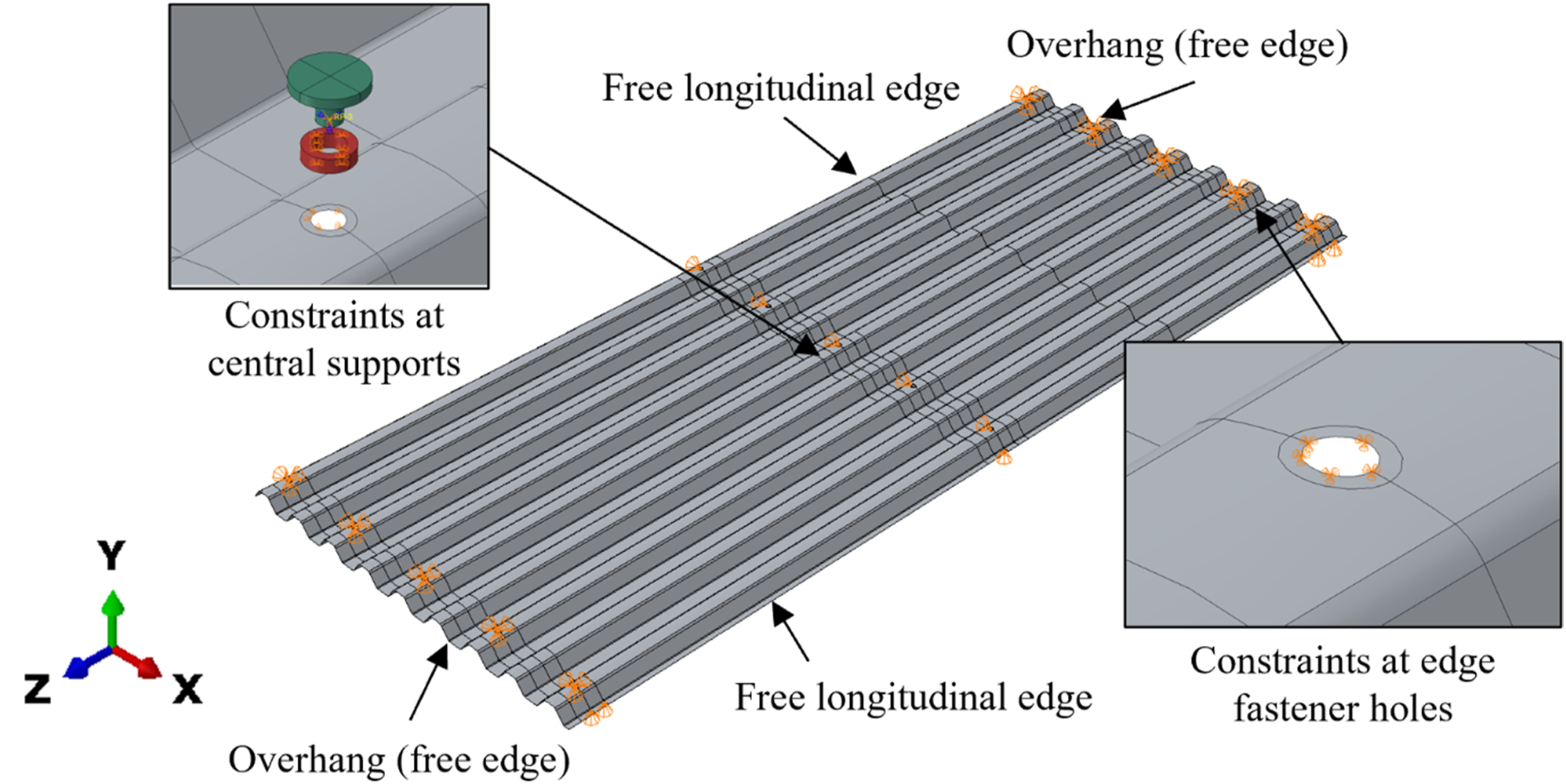
Further, capturing the interaction between the steel sheeting, neoprene washer, and screw head is crucial for realistic simulations. The neoprene washer primarily prevents the water leakage of the cladding and does not directly enhance the cladding assembly’s structural integrity. However, it influences the localized deformations and stress distributions around the fastener holes. To represent these effects, surface-to-surface contact interactions were defined for two interfaces: (i) washer–sheet, assigned a tangential friction coefficient of 0.4, and (ii) washer–screw head, assigned a coefficient of 0.5, consistent with the experimentally characterised friction behaviour of neoprene washers reported by Lovisa (2015). Hard contact was used in the normal direction for both interfaces. The screw threads were not explicitly modelled, as thread-bearing was not observed in any experiments; instead, the screw shaft was represented as a smooth cylindrical surface, and the X and Z translations of the washer’s inner surface were constrained to replicate the restraining effect of the screw passing through the hole, as shown in Figure 9. Finally, wind uplift/suction loading was simulated by applying a uniform surface pressure across the entire cladding assembly.
Geometric imperfections and residual stresses
In the nonlinear analysis of steel structures, it is standard practice to account for both geometric imperfections and residual stresses. However, residual stresses induced by the cold-forming process were excluded in this study, as their influence on the overall behaviour has been shown to be minimal (Mahaarachchi and Mahendran, 2009b). Likewise, initial geometric imperfections have a limited effect on the ultimate load capacity (Mahaarachchi and Mahendran, 2004; Pieper and Mahendran, 2023). This insensitivity is expected because pull-through failure is a highly localised mechanism governed by tensile membrane deformation and triaxial fracture directly beneath the screw head, typically at the second screw from the edge, rather than by global behaviour. As a result, variations in global imperfection amplitude or residual stress distribution have only minimal effect on the capacity, as confirmed by prior sensitivity studies. Although these factors do not affect the fracture-driven pull-through behaviour, a small initial geometric imperfection was still included to ensure numerical stability, facilitate smooth explicit analysis, and avoid convergence issues. To achieve this, an elastic buckling analysis was first performed, and the first eigenmode was adopted as the initial geometric imperfection shape, with an amplitude equal to the cladding thickness of 0.42 mm (Pieper and Mahendran, 2023).
Analysis method
Previous research on simulating crest-fixed claddings under wind uplift loading has employed different approaches. For instance, Pieper and Mahendran (2023) utilized the static general method, whereas Mahaarachchi and Mahendran (2009b) employed the static Riks solvers in Abaqus/CAE. In contrast, this study adopted the explicit analysis procedure to simulate both splitting and dimpling type pull-through failures of trapezoidal cladding. The explicit method was chosen for its ability to effectively incorporate damage mechanisms into FE simulations, making it particularly well-suited for modelling complex failure mechanisms. This approach provides several advantages, including the capability to handle complex contact conditions such as the interactions among the neoprene washer, cladding and screw head, large deformations, and instabilities. Furthermore, it enables accurate simulation of damage initiation and propagation, which is essential for analysing the splitting-type pull-through failure mechanism (Abaqus, 2012; Lovisa et al., 2013).
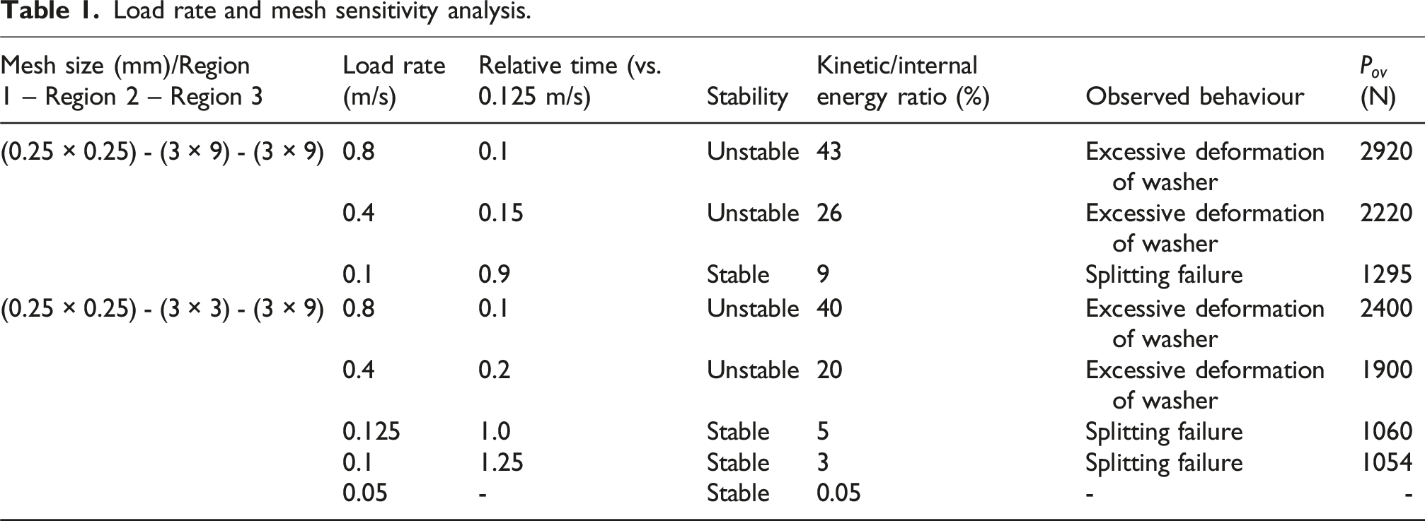
To accurately simulate the quasi-static behaviour of the cladding system under wind suction loading using the explicit solver in Abaqus, it is crucial to employ a sufficiently long total simulation time. This is due to the use of very small-time increments, influenced by the mesh element size and the material’s wave speed, which are necessary for maintaining numerical stability in explicit analysis. However, longer run times significantly increase computational demands. To address this, one approach is to increase the applied load rate, thereby shortening the total analysis time. This, however, risks introducing inertia effects that can compromise the accuracy of a quasi-static solution. To evaluate and mitigate this risk, a load rate sensitivity study was conducted. The aim was to identify the maximum load rate that could be applied without introducing significant dynamic effects. The key criterion was that the kinetic energy should remain below 5% of the total internal energy, as recommended by (Athmarajah et al., 2024; Lovisa et al., 2013), ensuring a quasi-static response.
Load rate and mesh sensitivity analysis.
Mesh sensitivity study
The FE model of the trapezoidal cladding with closely spaced ribs was meshed using S4R shell elements, a four-node element with reduced integration. These elements were chosen for their ability to efficiently capture transverse shear deformation, as well as in-plane membrane and bending actions, making them particularly suitable for simulating the behaviour of cladding under wind uplift/suction loading while maintaining computational efficiency. To ensure precise representation of the cladding’s profile and deformation, a maximum element size of 3 mm was selected. However, in the longitudinal (z) direction, larger element dimensions were used to minimize the total number of elements and reduce simulation time. But the aspect ratio was limited to a maximum of four to maintain accuracy, leveraging the versatility of shell elements (Abaqus, 2012). A mesh sensitivity analysis was conducted to determine the optimal element sizes, emphasizing their influence on solution convergence and ensuring a balance between accuracy and computational efficiency (Table 1). As summarised in Table 1, the adopted mesh densities were verified through the stabilisation of pull-through capacity once quasi-static conditions were achieved, with variations remaining within 3%. The table also highlights that higher loading rates introduce dynamic effects in explicit analysis, confirming the need for coupled adjustment of mesh size and loading rate to obtain a converged response. Figure 10 presents the discretised numerical model, showcasing the varying element sizes across three different regions. 1. Region 1: This region includes the area surrounding the screw holes, where significant variations in elastic and plastic strains were expected. To accurately capture localized plastic deformation and address convergence challenges, a finer mesh with an element size of 0.25 mm was applied near the edges of the screw holes. 2. Region 2: Extending 100 mm around the central screws, this region employed elements with an aspect ratio of 1 (3 mm × 3 mm) to ensure precise strain predictions and capture local deformations around the screw holes. 3. Region 3: Covering the area beyond Region 2, this region was meshed with an aspect ratio of 3, resulting in a mesh size of 3 mm × 9 mm. This optimized computational efficiency while maintaining sufficient accuracy. Meshing of trapezoidal cladding with closely spaced ribs.
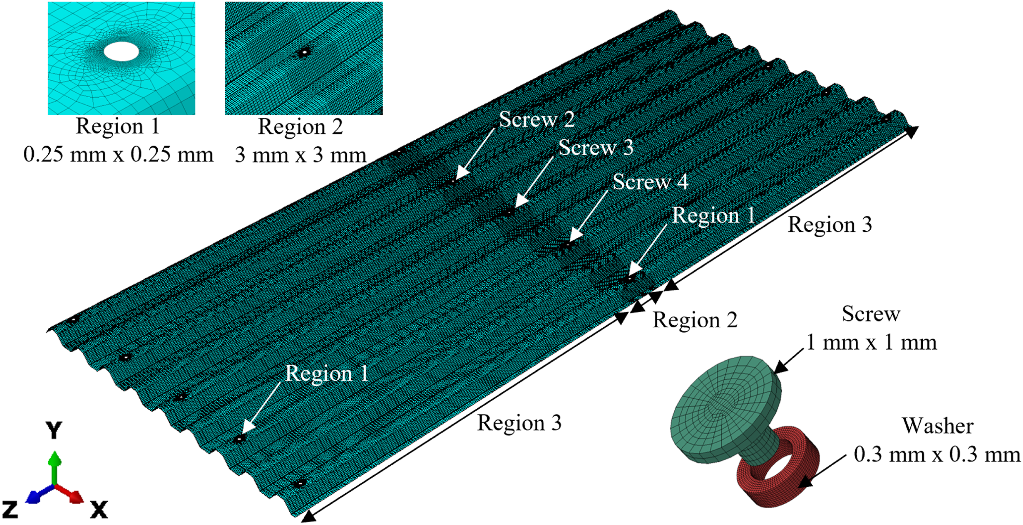
The self-drilling screw and neoprene washer were modelled using C3D8R elements, which are eight-node linear brick elements with reduced integration. To achieve high precision in modelling these components, the final mesh sizes were set to 1 mm × 1 mm for the screw head and 0.3 mm × 0.3 mm for the washer. This refined meshing strategy ensured the accurate prediction of strain distributions, localized deformations, and overall behaviour of the cladding assembly.
Validation of the FE model
Before conducting the detailed FE simulations, comprehensive load rate and mesh sensitivity analyses were performed to ensure the accuracy and numerical stability of the model. To validate the capability of the proposed FE model in predicting dimpling- and splitting-type pull-through failures, simulation results for the commercially available 0.42 mm thick G550 trapezoidal cladding with closely spaced ribs were compared against available experimental data from the literature. The FE model accurately reproduced the localised deformation behaviour observed in previous studies. As documented by Mahendran (1994), Mahaarachchi and Mahendran (2009b), and later by Pieper (2022), initial dimpling (Figure 11(a)) beneath the screw heads typically marks the early stages of failure. This is often followed by membrane action across the screw fastener region. With increasing load, the dimples expand (Figure 11(b) and (c)), leading to severe cross-sectional distortion (Figure 11(c)), similar to the behaviour observed in corrugated cladding systems. Eventually, at the higher loading level the cladding splits beneath the screws (Figure 11(d)), causing localised pull-through failure. In some experiments (Mahaarachchi and Mahendran, 2009b), the ribs were seen to flatten considerably without immediate pull-through (Figure 11(e)). However, with continued deformation, additional dimpling developed at the crest, and splitting failure occurred at a higher load level. The simulations showed substantial cross-sectional distortion, especially in the unfixed crest regions, where notable upward deflections occurred under wind uplift loading (Figure 11(f)). These results agree well with the deformation modes reported in two-span experimental cladding tests (Mahaarachchi, 2003; Mahaarachchi and Mahendran, 2009b; Pieper, 2022). This progressive failure mechanism leading to splitting type failure has been consistently reported across multiple experimental studies of the commercially available trapezoidal cladding profile and confirms the ability of the proposed FE model to capture the evolving nature of pull-through failure in trapezoidal cladding with closely spaced ribs. Progression of deformation in trapezoidal cladding with closely spaced ribs under wind suction loading: (a) initial dimpling (b) expansion of dimpling (c) cross-sectional distortion (d) splitting at screw hole (e) flattening of fixed crests and (f) overall deformed shape.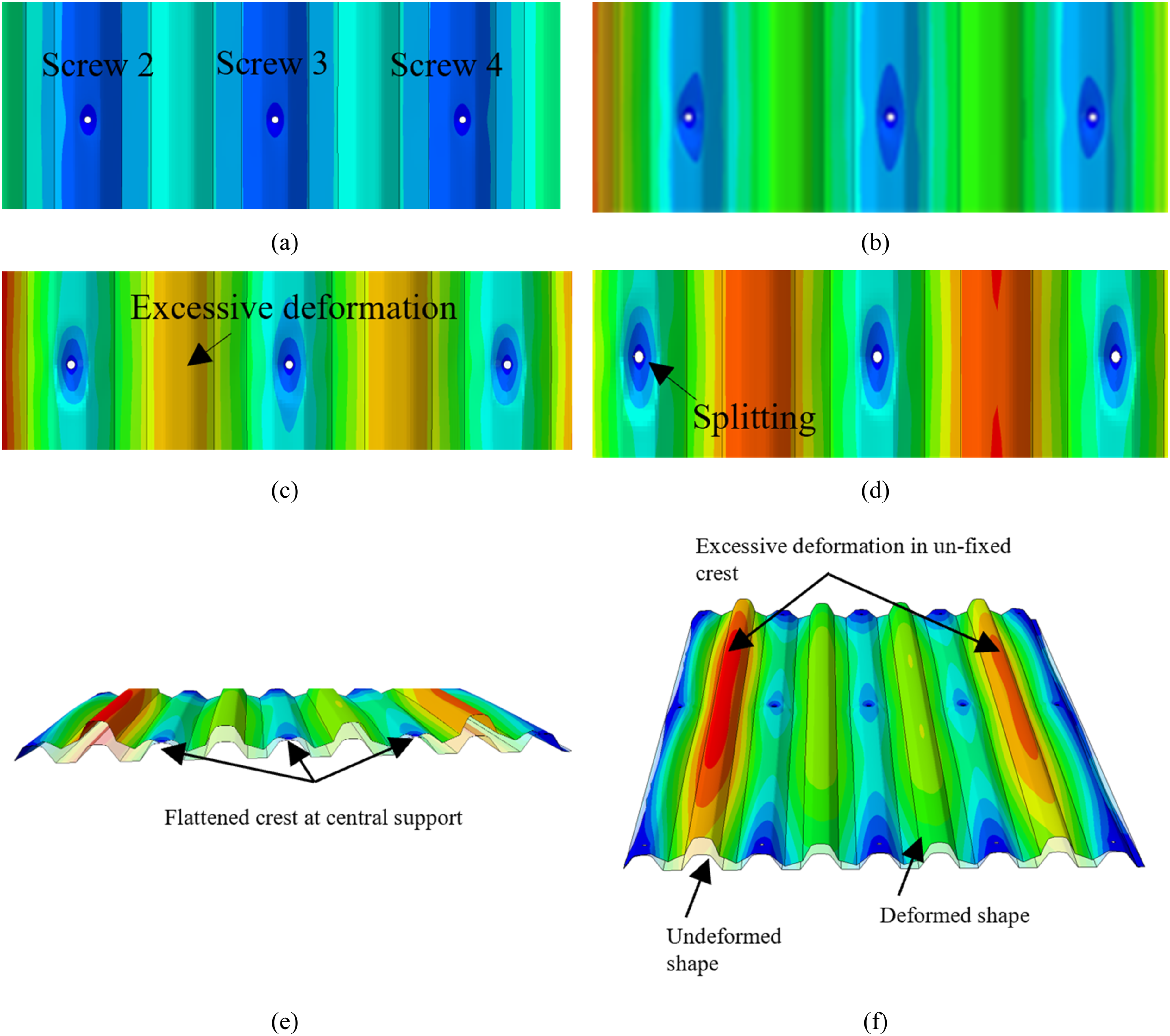
The failure behaviour of trapezoidal cladding with closely spaced ribs is known to exhibit characteristics intermediate between corrugated cladding, which typically fails by dimpling, and trapezoidal cladding with wide pans, which predominantly exhibits splitting-type failures (Mahaarachchi, 2003; Mahendran, 1994; Pieper, 2022). This duality is particularly evident in full-scale studies of crest-fixed trapezoidal cladding with closely spaced ribs. While small-scale tests have predominantly shown dimpling-dominated behaviour (Pieper and Mahendran, 2022), large-scale experiments have revealed a transition to splitting failure (Mahaarachchi, 2003; Mahendran, 1994; Pieper, 2022). This trend was also observed in Mahaarachchi and Mahendran’s (Mahaarachchi, 2003) full-scale tests, where initial dimples under the screw heads evolved into splitting-type failures at ultimate load. This transition in failure mode arises from the geometry of the trapezoidal cladding with close rib. Depending on specific geometric parameters, as well as the applied loading pattern and span length, the system may exhibit either failure mechanism. The detailed parametric study presented in the following section identifies the most influential geometric factors affecting this behaviour and provides further insight into the governing mechanics of pull-through failure in trapezoidal cladding with closely spaced ribs.
After verifying that the FE model accurately reproduced the local and global deformation patterns observed in experimental studies (Figure 11), further validation was undertaken by comparing the load-deflection curves and pull-through capacities against the experimental results of a two-span 0.42 mm thick trapezoidal cladding (each span 900 mm). As shown in Figure 12, the load–deflection curves from FE model and experiments exhibit good agreement, with upward deflections measured at the unscrewed midspan crest and reaction force at Screw 2 (critical screw) on the central support. The FE model captures both the elastic and nonlinear phases leading to failure. While the model predicts the splitting-type failure, it does not exhibit the abrupt post-peak load drop typical of wide-pan trapezoidal cladding. Instead, the curve progression aligns closely with experimental trends observed by Mahaarachchi (2003) and Xu and Reardon (1993), where a brief load reduction is followed by recovery due to membrane action in the flattened crest. Comparison of screw load versus deflection curves from experiments and FE analysis.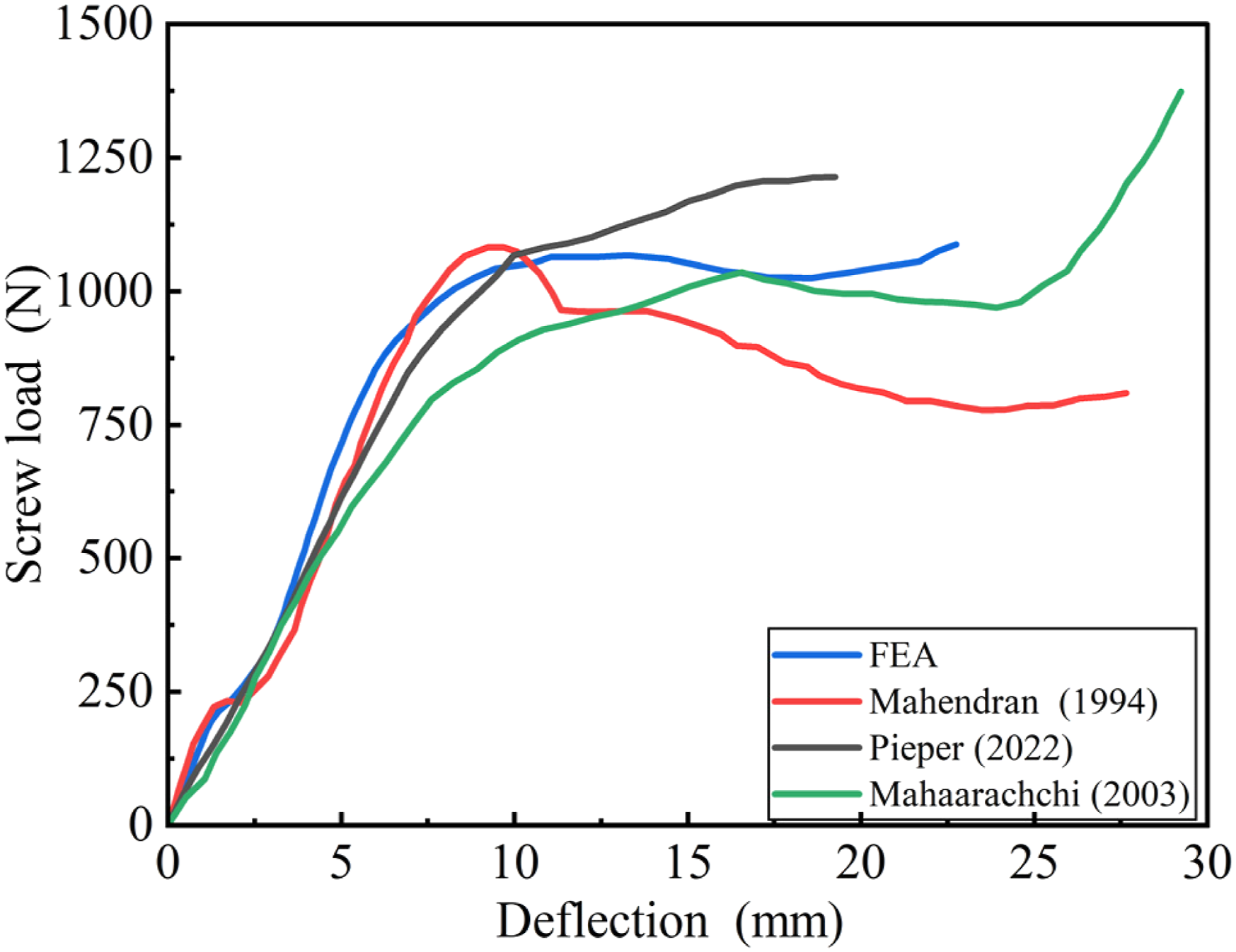
To further verify the robustness of the FE model, the predictions were compared against additional experimental datasets from past studies involving variations in span length and sheet thickness (Mahaarachchi, 2003). These comparisons showed consistently close agreement. For example, for a span of 1100 mm, the FE model predicted 1040 N compared with 1100 N obtained from experiment (−6% difference). For a 0.48 mm sheet thickness, the FE model predicted 1300 N compared to 1380 N from experiment (−5.5% difference). Across all cases evaluated, the FE model reproduced both the correct failure mode and the pull-through capacity within typical experimental scatter, confirming that the proposed modelling framework is accurate, reliable, and transferable across realistic cladding geometries.
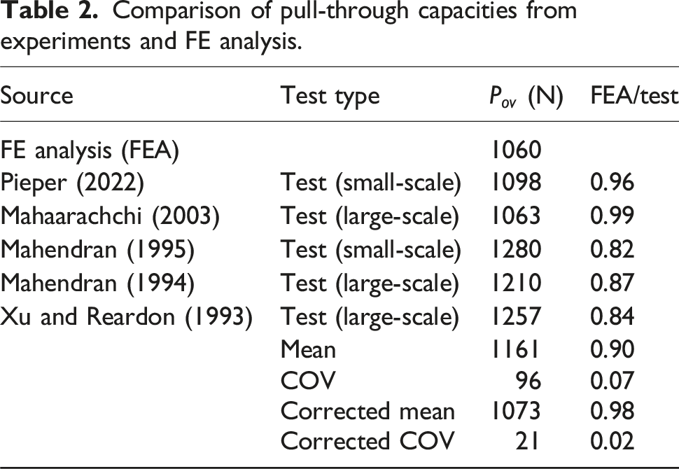
Comparison of pull-through capacities from experiments and FE analysis.
Investigating the effects of key parameters
A detailed numerical parametric study was conducted to investigate the effects of material properties, cladding geometric parameters, span, and screw head diameter on the localised dimpling/splitting based pull-through capacity of crest-fixed trapezoidal steel claddings with closely spaced ribs. The validated full-width FE model presented earlier was employed to evaluate both splitting- and dimpling-type failure loads across various configurations. The study explored a broad range of input parameters to examine their effect on failure behaviour and pull-through capacities. The analysed values included: base metal thickness
Effect of Young’s modulus
The effect of Young’s modulus ( Influence of Young’s modulus on pull-through capacity.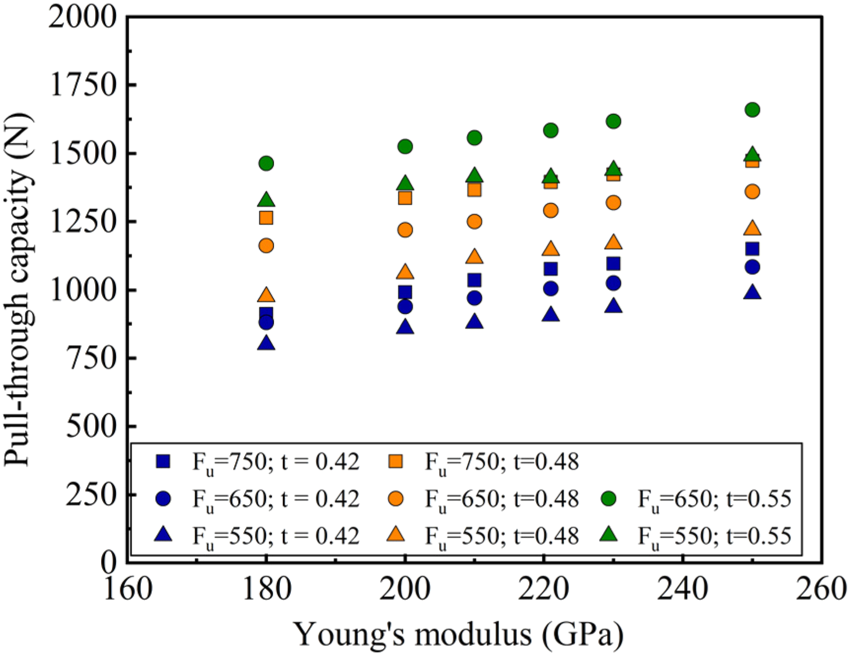
These findings underscore the strong combined influence of cladding thickness and elastic modulus on pull-through capacity. While higher
Effect of crest height
The effect of crest height ( Influence of crest height on pull-through capacity.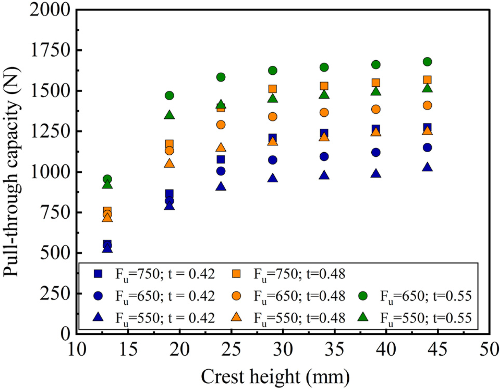
Beyond pull-through capacity, Failure modes for different crest heights (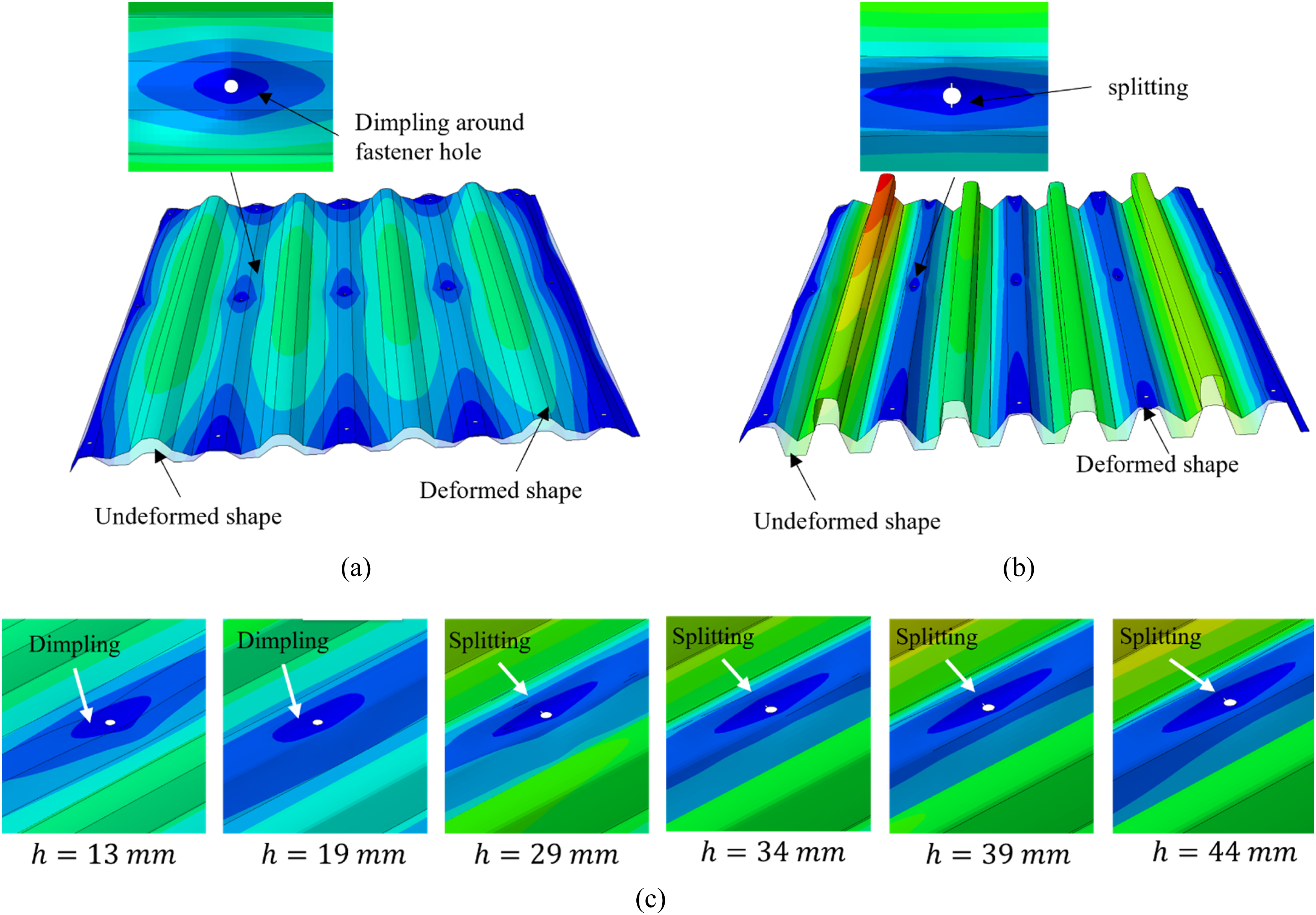
The results suggest that commercially available trapezoidal claddings with closely spaced ribs profiles with
Effect of radius of crest
The radius of crest Influence of radius of crest on pull-through capacity.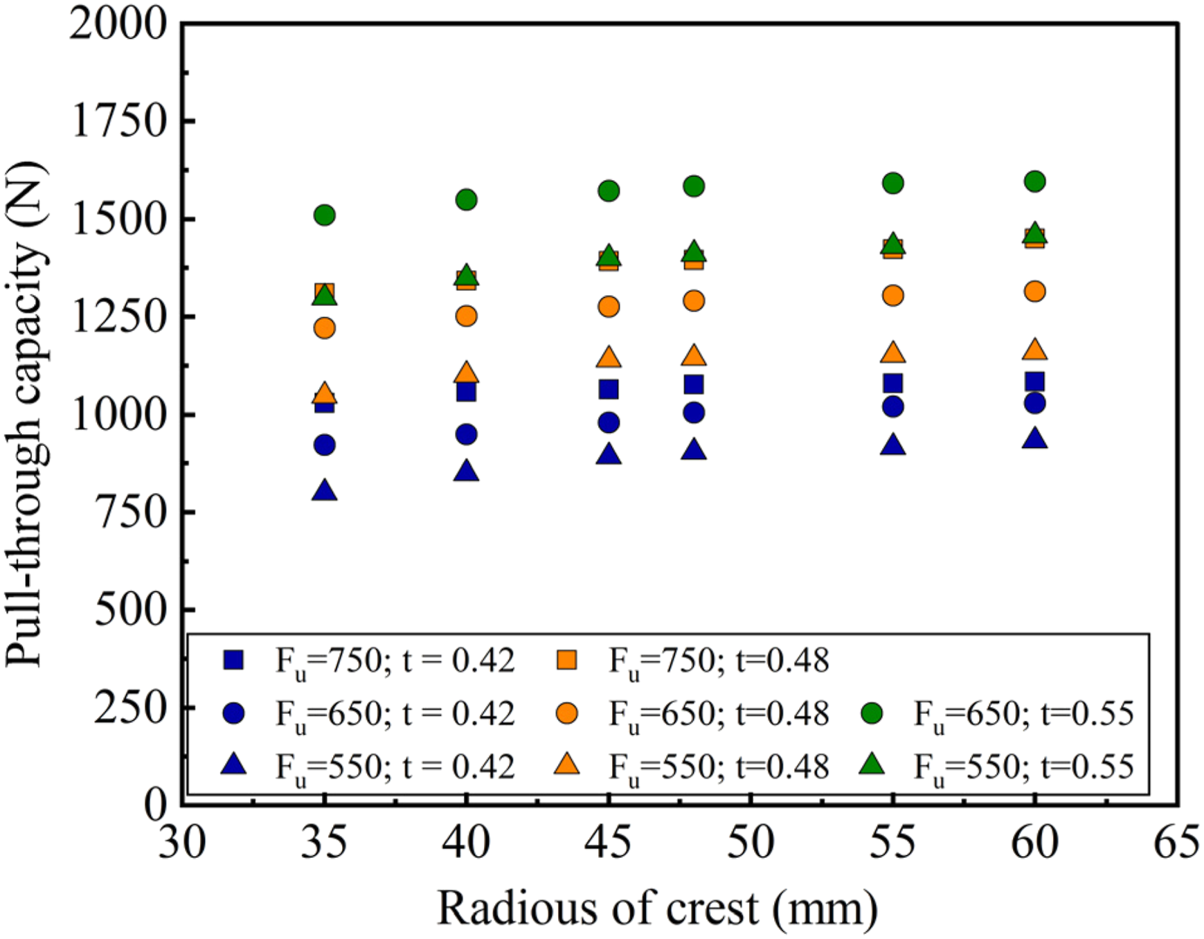
Similar behaviour is observed at
These observations imply that
Effect of crest width
The effect of crest width ( Influence of crest width on pull-through capacity.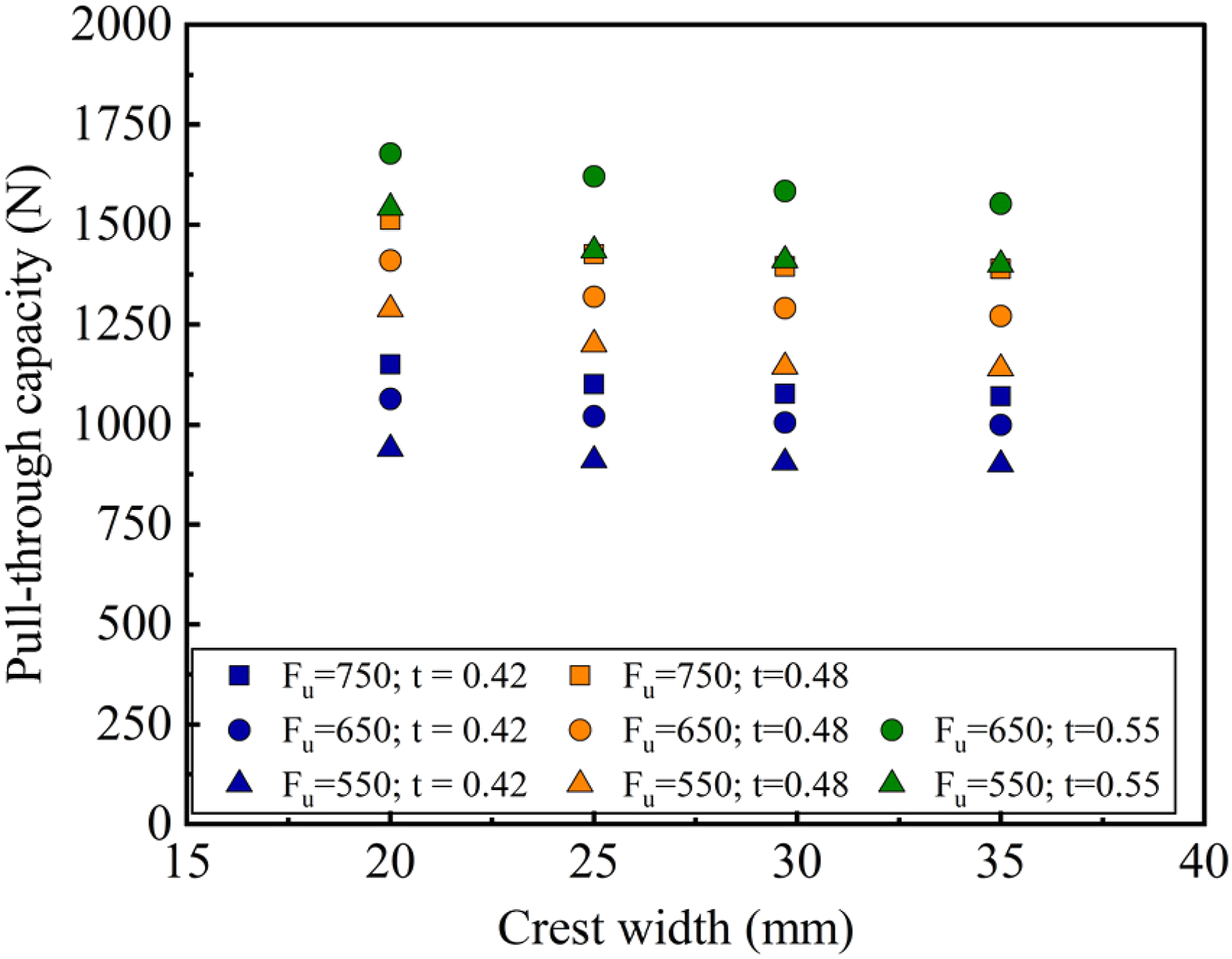
In terms of failure mode as shown in Figure 18, narrow crests often led to dimpling-type failures, while wider crests were more associated with splitting. Interestingly, some narrow crest configurations showed high pull-through capacities despite dimpling-type failure. The increased curvature in narrower crests causes the cladding to bend more tightly around the screw, which improves stress distribution and delays crack initiation. This promotes stable plastic deformation, unlike wider crests that develop stress concentrations and fail earlier by splitting. Deformation pattern with increasing crest width: (a) 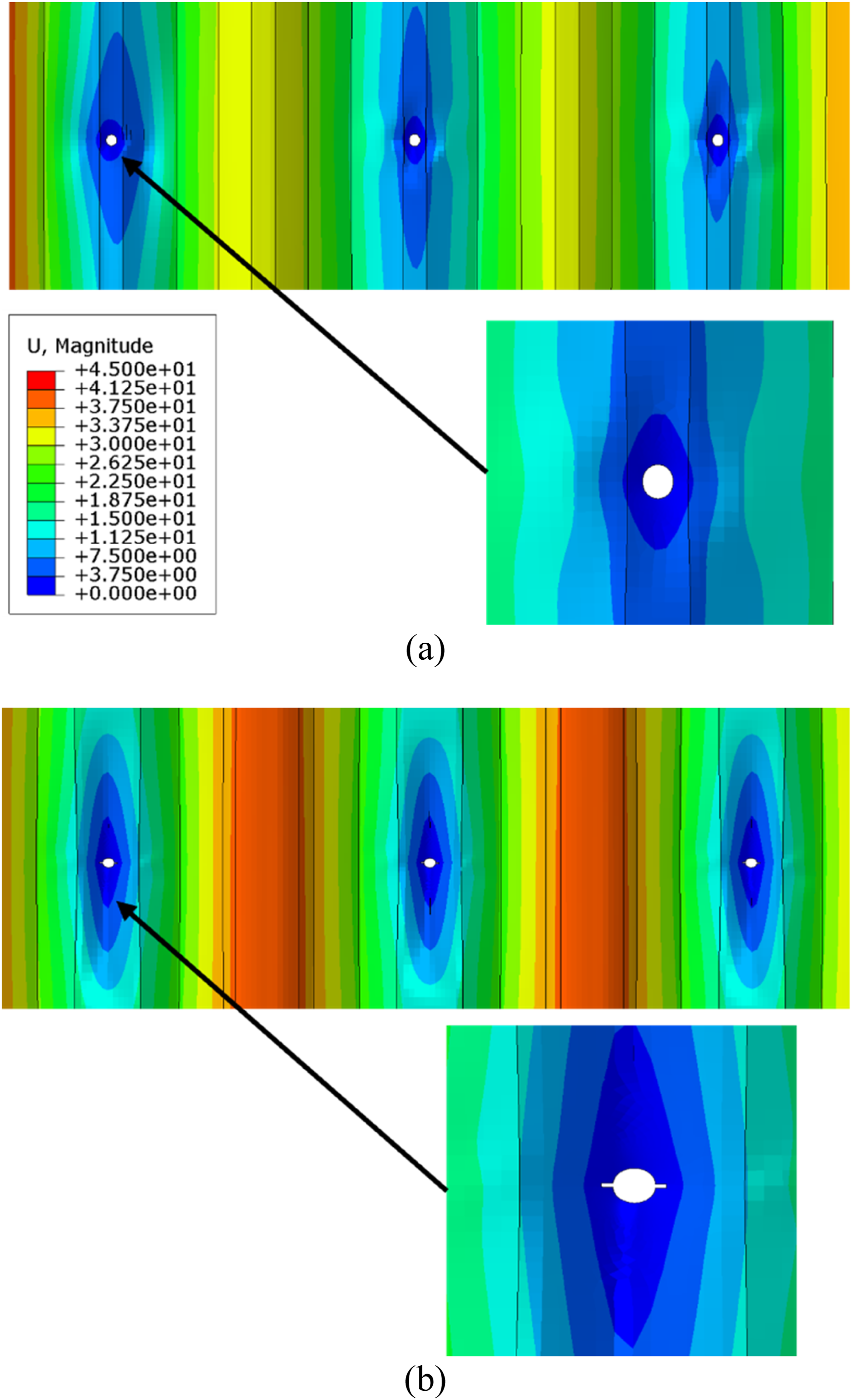
Effect of trough width
The trough width Influence of trough width on pull-through capacity. Deformation patterns with increasing trough width: (a) 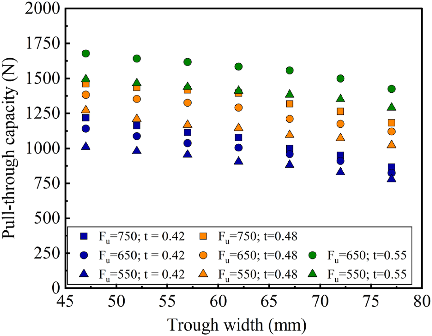
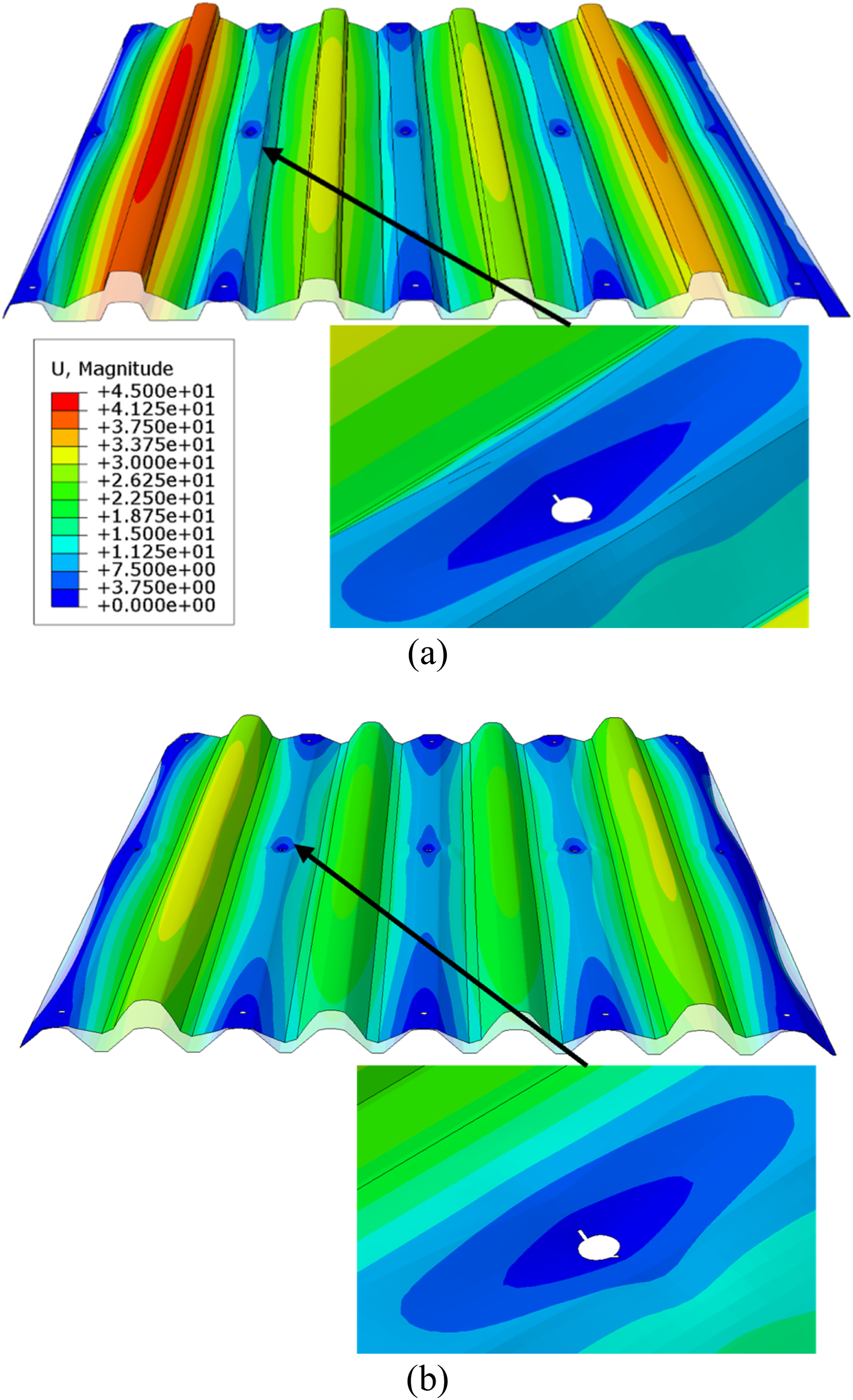
Effect of pitch
The pitch Influence of pitch on pull-through capacity.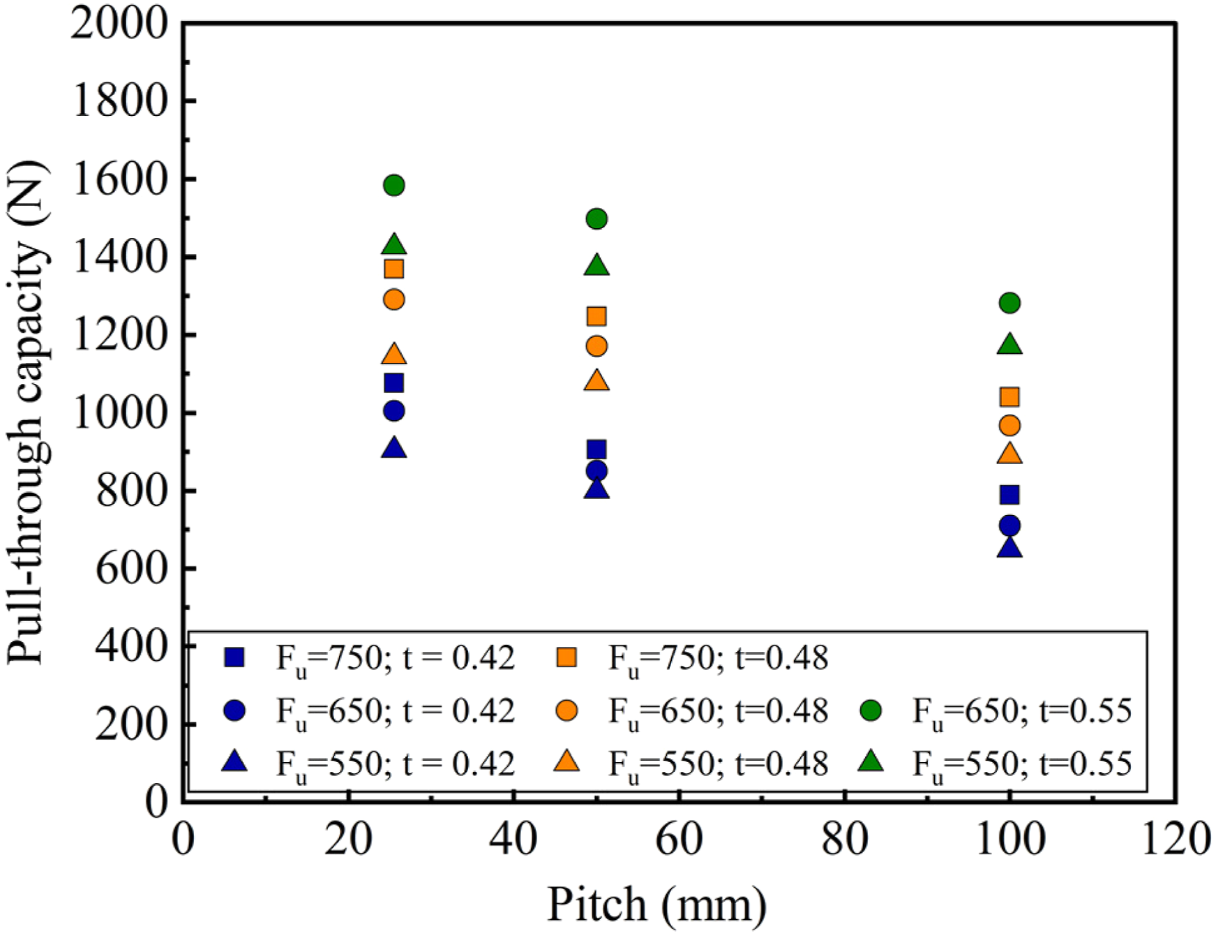
These reductions in capacity are intricately linked to the deformation pattern. As shown in Figure 22, which presents failure modes for Comparison of deformed and undeformed shapes: (a) 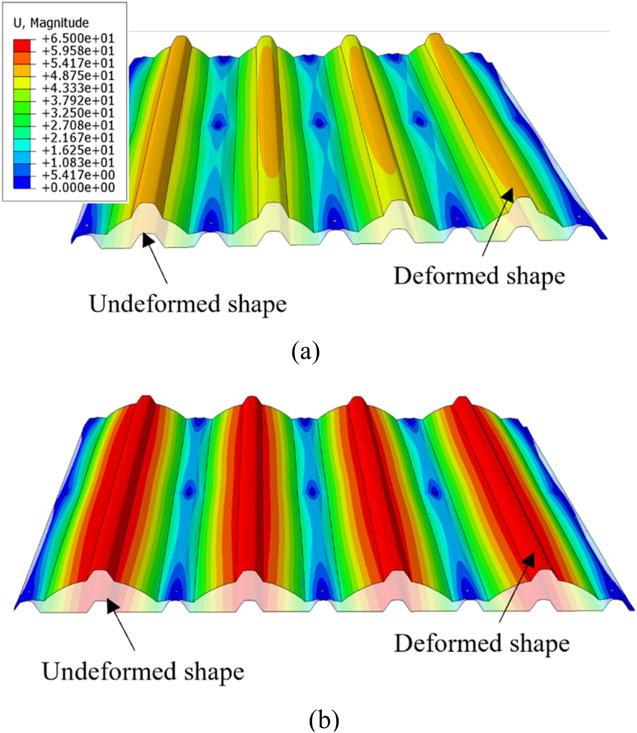
Effect of screw head diameter
The screw head diameter Influence of screw head diameter on pull-through capacity.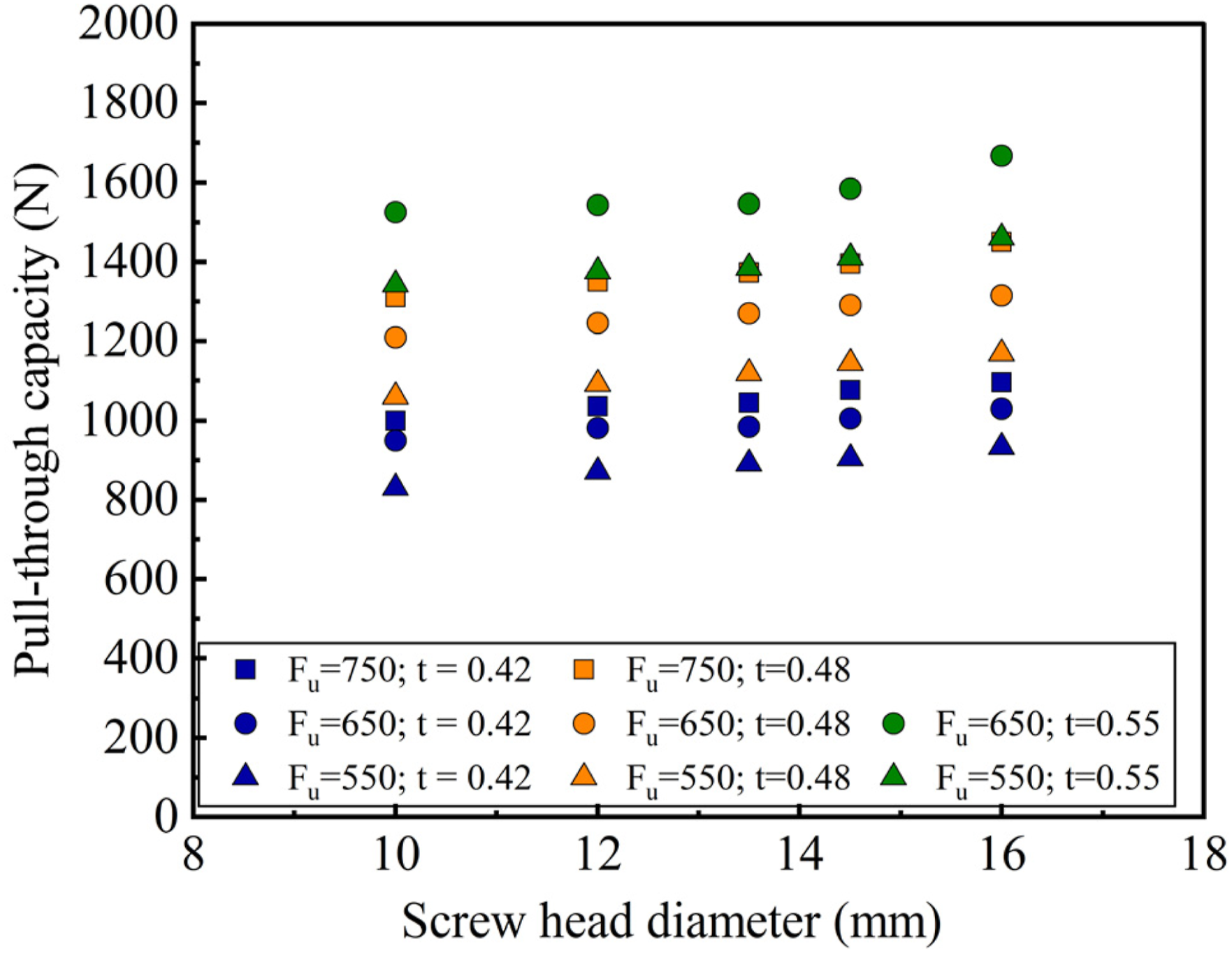
Effect of span
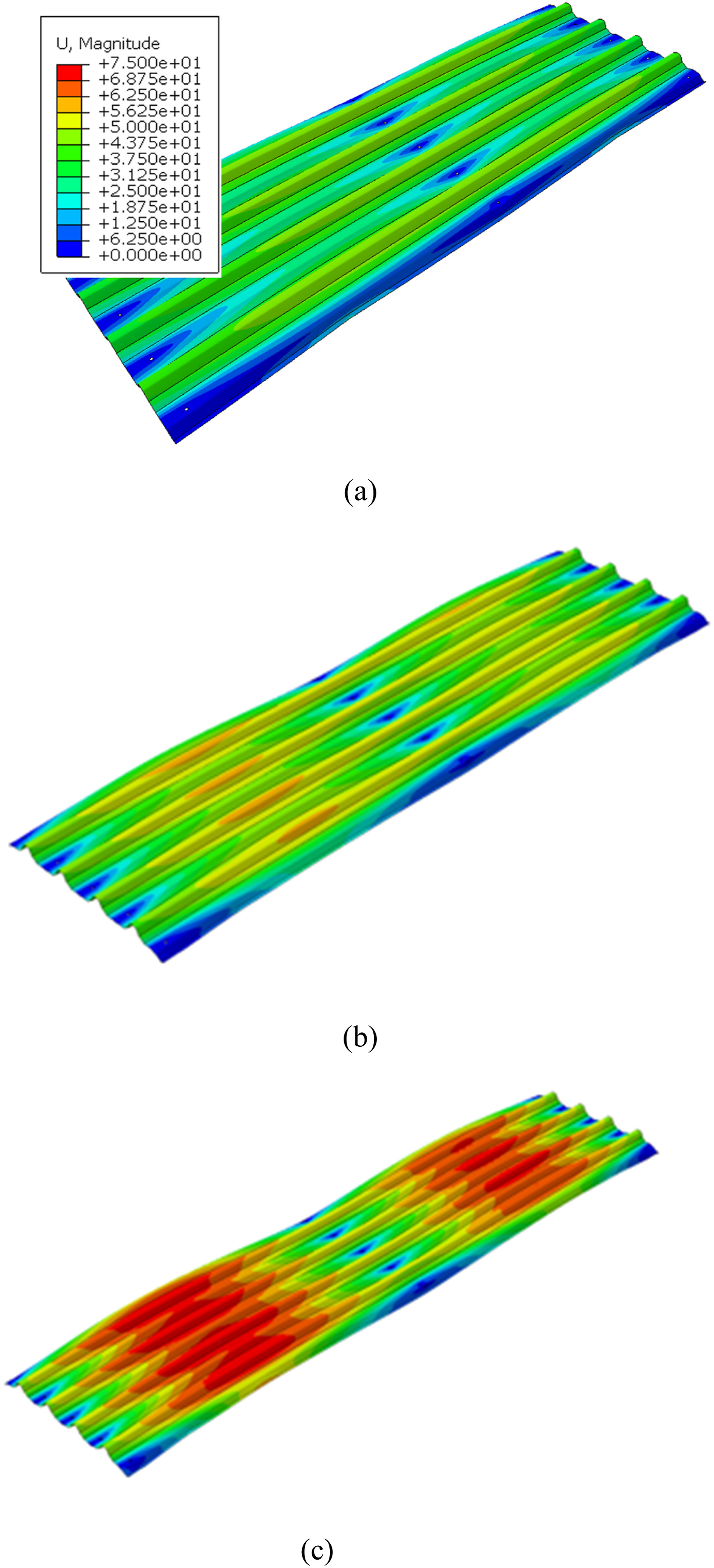
The effect of span Influence of span on pull-through capacity. Mid-span deflection of cladding with increasing span (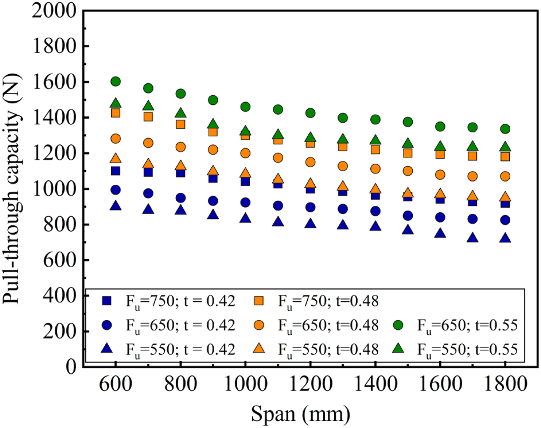
Development of new pull-through capacity equations
Existing design equations
The design of crest-fixed trapezoidal claddings has traditionally relied on empirical equations to estimate the pull-through capacity under wind uplift loading. This section reviews several notable design equations, discussing their key assumptions and known limitations, as a precursor to proposing new equations suited for crest-fixed trapezoidal cladding with closely spaced ribs.
AISI S100 and Eurocode 1993
Current American CFS design specification, AISI S100 (AISI, 2016) offers equations (9) and (10) to estimate the pull-through capacity of CFS sheeting.

On the other hand, Eurocode 1993 (CEN, 2005) provides a similar equation (Eq. (11)) based on characteristic yield strength 
These equations were originally developed for low-strength valley-fixed cladding and do not adequately represent the failure mechanisms observed in thin, high-strength crest-fixed cladding systems subjected to wind uplift, particularly local dimpling and splitting-type pull-through failures. Furthermore, both the AISI and Eurocode approaches assume a ductile material response, which may not be applicable to thin, high-strength steels such as G550, especially when the sheet thickness is below 0.9 mm. To account for the reduced ductility of such materials, a strength reduction factor of 0.75 is commonly applied. Although the AISI equation has been adopted in AS/NZS 4600 (Standards Australia, 2018), it remains uncalibrated for uplift conditions (which is the primary loading condition in Australia) and therefore tends to overestimate the pull-through capacity in crest-fixed configurations. Hence the design of screw-fastened claddings in Australian practice still relies heavily on laboratory testing.
Mahendran and Tang (1999)
To address the limitations in the above equations, Mahendran and Tang (1999) proposed a generalised pull-through capacity equation for crest-fixed steel cladding systems under wind uplift, equation (12)
While this equation improves upon AISI S100 (AISI, 2016), it has several limitations. The FE models adopted an elastic perfectly plastic material behaviour without including any damage criteria, making them unable to simulate splitting-type failures at the fastener holes. Furthermore, the model was validated using average fastener loads from two-span tests, which do not accurately reflect localized failure at critical screws where the actual pull-through load is typically lower than the average. Further, the equation does not consider the influence of cladding profile geometry explicitly. Although it reasonably captures dimpling-type failure modes in ductile steels, it does not reliably predict splitting-dominated failures, particularly those observed in thin, high-strength cladding materials such as G550.
Mahaarachchi and Mahendran (2009b)
Mahaarachchi and Mahendran (2009b) proposed a refined equation (equation (13)) for trapezoidal CFS claddings with closely spaced ribs through large-scale air-box tests and numerical analyses.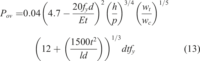
Equation (13) represents a more direct effort to capture localized behaviour by observing the failure of individual screws rather than averaging loads across multiple fasteners. However, their FE models employed a separate experimentally determined strain criterion to detect splitting, rather than incorporating an explicit fracture or damage progression in the steel. Consequently, the reliability of this approach for high-strength CFS claddings with closely spaced ribs remains uncertain. Additionally, the criterion was primarily calibrated for wide-pan trapezoidal profiles, and its suitability for closely spaced rib configurations where dimpling and splitting failures may interact has yet to be validated.
Collectively, these existing equations underscore the challenges of accurately predicting the pull-through capacity of crest-fixed, thin high-strength trapezoidal cladding with closely spaced ribs under wind uplift. The AISI S100 (AISI, 2016) method suits valley-fixed, lower-strength profiles and overestimates the capacity of crest-fixed claddings. Mahendran and Tang’s (1999) equation overlooks critical splitting behaviour by assuming unlimited ductility. Similarly, Mahaarachchi and Mahendran’s (2009b) refined equation relies on a strain criterion without explicitly modelling material damage and is validated for wide-pan geometries. Hence, no current design equations fully encompass the distinct behaviour of trapezoidal cladding with closely spaced ribs, where local dimpling, splitting, or a mixture of both can govern the pull-through failure mechanism. This gap motivates the development of a new equation that integrates a broader range of geometric and material factors, accurately reflecting both fracture and plasticity phenomena in high-strength steels.
Proposal of new equation
This section develops a new design equation that accurately reflects the localized pull-through capacity of crest-fixed trapezoidal cladding with closely spaced ribs, where both splitting- and dimpling-type failures may occur. Thin, high-strength crest-fixed steel cladding exhibits a complex response to wind uplift loading, influenced by factors such as profile geometry, material properties, fastener characteristics, and span. The interaction of these variables makes it challenging to derive a simple theoretical or empirical expression linking failure load to these parameters. To systematically address these complexities, Buckingham’s
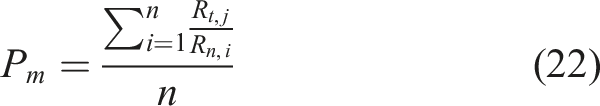
As an initial step, the pull-through capacity 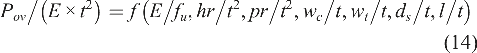
Although each dimensionless variable was initially considered independently, a multi-variable regression analysis showed that the localized pull-through behaviour of crest-fixed trapezoidal cladding with closely spaced ribs proved to be dominated by interactions among these parameters rather than their individual effects. Consequently, the analysis shifted from single-parameter to combined π-group correlations, resulting in a more comprehensive function that captures the interplay between geometry, fastener characteristics, and span. This enhanced model is presented in equation (15), thereby improving the predictive accuracy for pull-through capacity.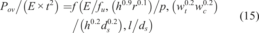
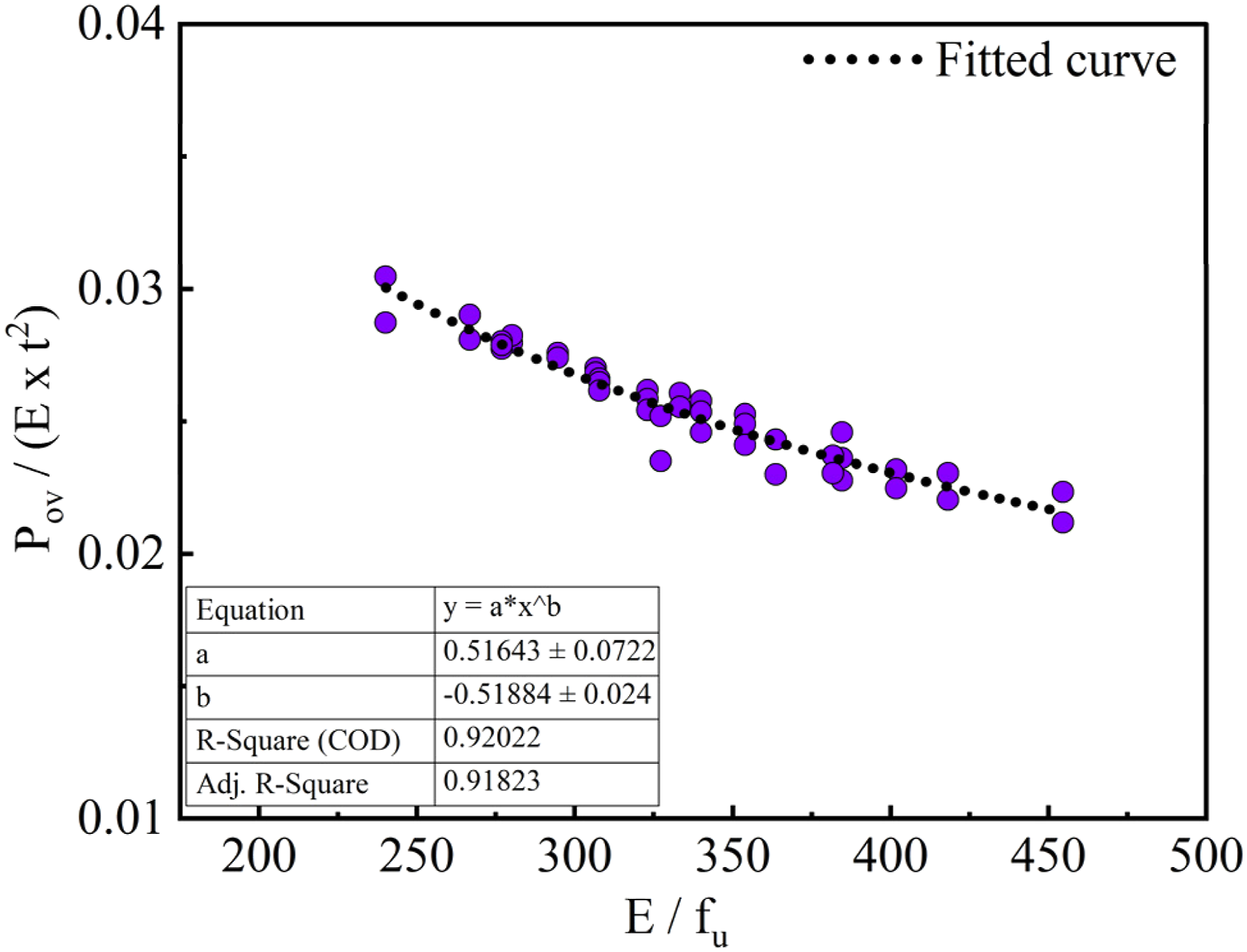
To establish the relationship between Data fitting for 
By normalizing Data fitting for 
The proposed design equation for the pull-through capacity of crest-fixed trapezoidal cladding with closely spaced ribs, expressed in equation (17), integrates multiple geometric and material parameters identified as most influential in governing failure under wind uplift. Specifically, it reflects the combined effects of 

These factors collectively determine whether cladding sections near the fastener experience localized dimpling or splitting-type failures, making them critical for accurately predicting pull-through capacity.
In equation (17), the constants (e.g., 0.51, and the exponents on
Figure 28 provides a visual comparison between the measured pull-through capacities Comparison between predicted and actual 
Taken together, these findings demonstrate that equation (17) offers a robust, yet practical design tool for engineers and designers dealing with crest-fixed trapezoidal cladding with closely spaced ribs. By incorporating geometric factors
Capacity reduction factor
A capacity reduction factor 

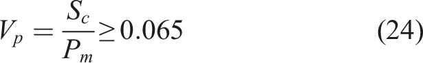
Substituting all values into equation (21) led to a capacity reduction factor ϕ of 0.69. However, AS/NZS 4600 (Standards Australia, 2018) specifies a more conservative value of 0.5 for screwed connections prone to pull-through failures. Based on the demonstrated accuracy and reliability of the proposed equation, a ϕ-factor of 0.65 is recommended for use with equation (17).
Conclusion
This study has presented a detailed numerical investigation into the pull-through failures of crest-fixed trapezoidal cladding with closely spaced ribs subjected to wind uplift loading. A comprehensive FE model incorporating an advanced ductile damage material model was developed and validated against experimental data. The model successfully captured both localized dimpling and transverse splitting failure modes, highlighting the complex pull-through behaviour of high-strength, thin-gauge cold-formed steel cladding systems, and reduced the FE/Test discrepancy to about 2% with a low coefficient of variation of 0.02. • A ductile damage material model was developed for high-strength G550 steel and validated through coupon test simulations. The model accurately replicated both the onset and progression of damage, including post-necking softening and fracture. • This validated damage model was incorporated into a full-width FE model of trapezoidal cladding with closely spaced ribs, which successfully predicted the pull-through capacities and associated failure modes, demonstrating good agreement with existing small- and large-scale experimental data. • A detailed parametric study investigated the influence of key factors, including material properties (Young’s modulus and ultimate strength), geometric parameters (crest height, crest width, trough width, pitch, and radius of crest), fastener characteristics (screw head diameter), and cladding span. • The results showed that increasing thickness, Young’s modulus, and crest height significantly enhances pull-through capacity by up to 90%. Conversely, wider troughs, larger pitch, and longer spans tend to reduce the capacity by up to 29%. Interaction among these geometric factors was found to shift the failure mode between dimpling and splitting. • Crest width, crest height, and span had a pronounced influence on the failure mode. Narrower crests with higher curvature promoted stable dimpling-type failures with higher capacities, while wider crests and larger crest height increased the likelihood of splitting. • Based on the simulation results, a new pull-through capacity equation with a capacity reduction factor of 0.65 was proposed, incorporating material properties, geometric dimensions, screw fastener diameter, and span. The proposed equation showed excellent agreement with FE results, with a maximum variance of 5% and a mean prediction ratio of 1.019. It can be used to determine the wind uplift/suction strength of cladding systems.
This new design approach provides a reliable and practical tool for predicting the pull-through behaviour of crest-fixed trapezoidal cladding systems and can assist in optimizing existing profiles or developing new profiles.
Future work will extend this modelling framework to cyclic/fatigue loading, and uneven wind pressure distributions. Additional studies will also investigate the influence of larger or alternative washer systems, and broader experimental datasets to support future calibration for possible inclusion in AS/NZS 4600 or related design standards.
Footnotes
Acknowledgements
The authors would like to thank Australian Research Council (DP190102846) for the financial support and Queensland University of Technology (QUT) for the provision of computing facilities to conduct this study.
Funding
The author(s) disclosed receipt of the following financial support for the research, authorship, and/or publication of this article: this work was supported by the Australian Research Council (DP190102846).
Declaration of conflicting interests
The author(s) declared no potential conflicts of interest with respect to the research, authorship, and/or publication of this article.