
Abstract
The linear analysis with limited moment redistribution is useful to reduce the maximum negative moments at support sections, bringing this way several advantages to design and execution of reinforced concrete beams and slabs. The maximum moment redistribution is not related only with the plastic rotation capacity of the critical sections, but also with the requirements at the Serviceability Limit States. The main structural concrete codes condition the maximum moment redistribution to the ductility of the sections and to the ductility of the steels used. The goal of this study is to analyze how the limitation of crack width under service conditions affects the maximum moment redistribution used in the analysis to the Ultimate Limit States. On the other hand, with the increasing use of high-strength steels, it is important to assess how this type of steels can limit the moment redistribution and how they influence the crack width. It was found that the maximum moment redistribution is significantly conditioned by the limitation of the maximum crack width and by the qSLS/qULS ratio, which is the ratio between the load corresponding to the service conditions (qELS) and the load used on the verifications of the Ultimate Limit States (qELU). In certain situations, the maximum moment redistribution possible was lower than the values recommended by main codes, Eurocode 2 and fib Model Code. To exploit the full capacity of high strength steels, the moment redistribution must be very limited and applied only on structures located in less aggressive environments. To understand all effects of the moment redistribution, a non-linear analysis was also performed to analyze the real evolution of the moment distribution along the beam axis for different load levels. Based on the study performed, it is proposed an empirical equation to predict the maximum moment redistribution allowed, considering all key parameters.
Introduction
In traditional reinforced concrete structures, the moment diagram from a linear elastic analysis usually shows some peaks representing the sections with maximum negative moments. If those sections were properly designed to have ductile behavior, a plastic hinge can appear at a certain loading stage, modifying the distribution of the internal forces for higher loads. This change, in relation to what is predicted by linear elastic analysis, is called moment redistribution and occurs due to flexural stiffness reduction in certain sections, initially due to concrete cracking and later, for higher loads, due to yielding of the steel rebars. On the sections where the reinforcement reaches the yield strength, the stiffness decrease is so significant and the rotations are so high for small variations of the applied load that a plastic hinge is considered to have been formed (Carmo, 2004; Li et al., 2019; Lou et al., 2014; Muhamad et al., 2013; Oehlers et al., 2015; Wu, 2022). The redistribution of internal forces is related to the ductility of the critical sections because are the plastic deformations that allows to have relative rotation between two adjacent elements with practically no increase in moment. Consequently, other sections have to withstand higher moments due to the increased load. The redistribution of the internal forces only happens in hyperstatic structures if the remaining sections have not already achieved their maximum strength.
The concept of moment redistribution arises when the actual distribution of internal forces in a structure is compared to that predicted by linear elastic analysis. In this context, it is important to emphasize that linear elastic analysis remains the most widely used method for reinforced concrete structural design, primarily due to its simplicity and the inherent safety margin it provides. Linear analysis with moment redistribution is a method for determining the internal forces in a structure based on linear elastic analysis, considering the non-linear behavior of reinforced concrete elements. This approach is an alternative significantly simpler to non-linear analysis. This analysis involves reducing the maximum negative moments by a specific magnitude (using the coefficient δ) and correspondingly increasing the positive moments to satisfy the conditions of static equilibrium between the applied loads and the internal forces (Figure 1). The degree or coefficient of moment redistribution, δ, is defined as the ratio between the redistributed moment, Mred, and the linear elastic moment, Mel (equation (1)). Elastic and redistributed moment diagrams.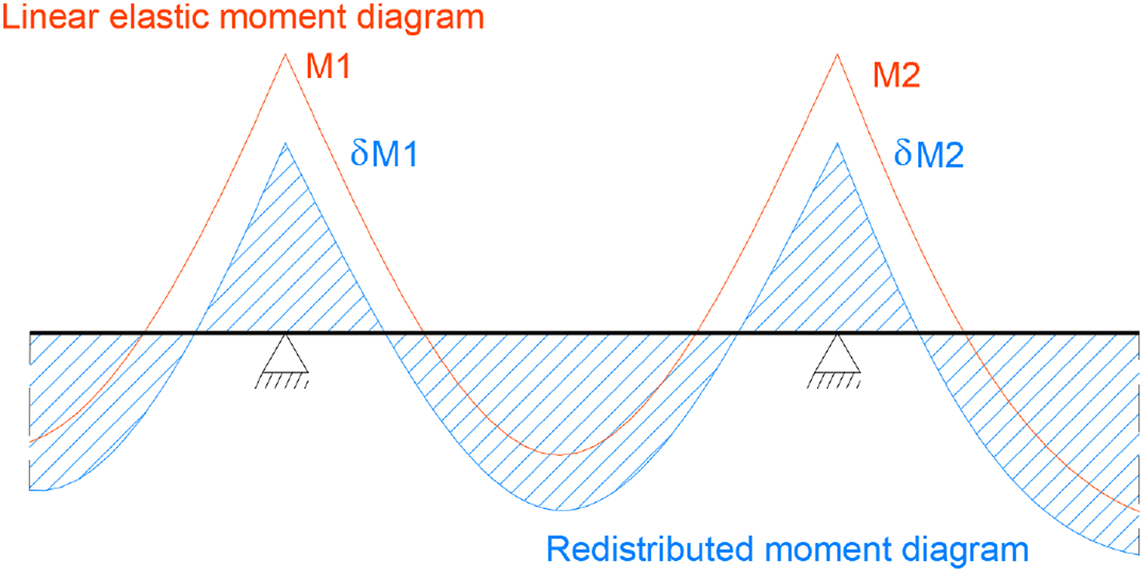
This attenuation of the peaks can bring several advantages, such as: i) it allows to exploit the reserve of strength of hyperstatic structures; ii) it gives greater freedom to define the longitudinal reinforcement; iii) it reduces the maximum stress on compressed regions and the area of tension reinforcements in the most stressed sections (less reinforcement congestion), improving the conditions of concrete casting; iv) it reduces the vertical reaction at the intermediate supports, resulting in a reduction of the shear force in that region (Carmo and Lopes, 2005a).
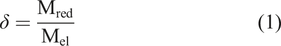
Redistribution coefficient for a linear analysis with moment redistribution.
The degree of moment redistribution, δ, depends on the plastic rotation capacity of the critical sections, which is directly related to the ductility of steel and x/d parameter (ratio between the neutral axis depth and the effective depth of the cross section). The x/d parameter is widely used because it effectively reflects, within defined limits, the influence of several factors that affect the plastic rotation capacity, like: i) longitudinal tensile reinforcement ratio; ii) ductility of the reinforcement; iii) longitudinal compressive reinforcement ratio; iv) transversal reinforcement ratio; v) concrete strength; vi) dimensions and shape of the cross section (Carmo et al., 2003; Carmo, 2004; Carmo and Lopes, 2005b). The greater the moment redistribution used in the analysis, the higher the ductility demand, and consequently more restricted is the neutral axis depth, x/d. The value of x/d can be easily determined, as there are well-established relations between this parameter and the mechanical reinforcement ratio of the sections. The ACI 318-19 adopts a different approach to ensure that critical sections have enough plastic deformation capacity by defining limits based on the net tensile strain, ε t .
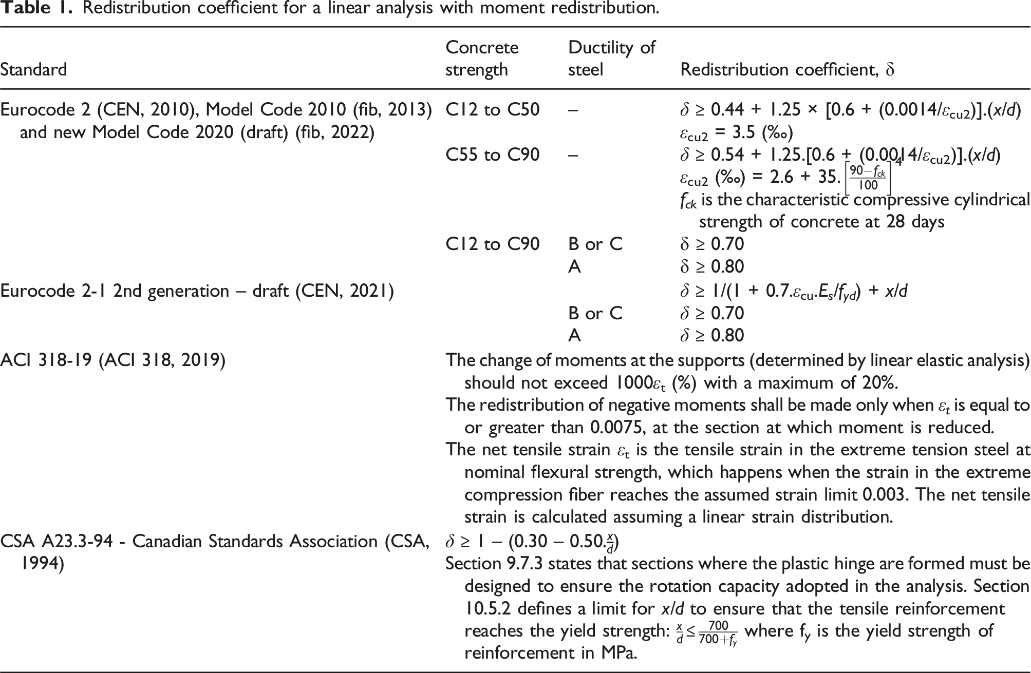
The relation between the degree of moment redistribution and the parameter x/d also depends on the required plastic rotation, which is influenced by equilibrium conditions and compatibility of deformations. Both required plastic rotation and plastic rotation capacity of critical sections can be related with the x/d, and by intersecting the two curves, the maximum value of x/d can be determined, for each degree of moment redistribution (Figure 2). The equations recommended for linear analysis with moment redistribution presented in some structural codes, like Eurocode 2 (CEN, 2010) and fib Model Code 2010 (fib, 2013), were obtained using this procedure (see Table 1). Although the new fib Model Code 2020 (fib, 2022) and the 2nd generation of Eurocode 2 (CEN, 2021) still be a draft, it was considered valuable present the new equations to calculate the maximum moment redistribution allowed. Relation between required and available plastic rotation as a function of x/d (Carmo and Lopes, 2006).
Some researchers argue that the question is not whether this procedure can be used, but whether it should be applied more frequently. Moment redistribution can be utilized to optimize structural design, particularly in continuous beams or slabs. It can also be employed in the assessment of existing structures for scenarios such as changes in use or increased loading. In such cases, any reserve capacity in the existing reinforcement layout at the mid-span can be leveraged to compensate for deficiencies at the supports (spbeam, 2018). Practical examples can be found in the literature where moment redistribution is applied in the design of new structures to reduce top reinforcement at interior supports, thereby alleviating rebar congestion in those regions (spbeam, 2018).
Until now, the focus has been on understanding moment redistribution in structural design and on highlighting how important is the verification of the plastic deformation at the supports, to ensure that there is enough ductility to accommodate the assumed moment redistribution. But there are other issues to be considered. The redistribution of moments influences the reinforcement ratio, which is crucial for the analysis of deflection and crack width.
According to König (König and Pommerening, 1997), for the analysis at the Ultimate Limit States (ULS) is not recommended to perform a moment redistribution higher than 20% because of the limitations imposed on the Serviceability Limit States (SLS), particularly on crack control. With the reduction of the cross-sectional area of the longitudinal reinforcement required for the ULS verifications, the tensile stress might increase significantly in a way that, under the service conditions, the limits imposed to maximum crack width may be exceeded.
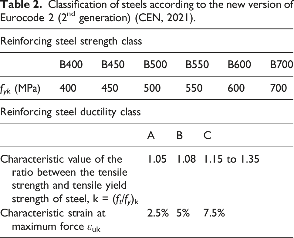
Although studying moment redistribution continues to attract attention from engineers and researchers, there are neither or very few studies about the maximum limits allowed for moment redistribution, where the constraining factor is the verification of the maximum crack width under service conditions. Most codes state that this limit is 20% or 30% (Table 1), depending fundamentally on the ductility of the steel used. With the production and use of high-strength steels, the question arises as whether these redistribution limits are also valid for high-strength steels. The new versions of structural concrete codes, namely the 2nd generation of Eurocode 2 (CEN, 2021), allow the use of high-strength steels but do not address these implications.
Classification of steels according to the new version of Eurocode 2 (2nd generation) (CEN, 2021).
The use of high-strength steel can be beneficial in reducing the quantity of reinforcement required in structural members, thereby decreasing rebar congestion. This is particularly advantageous as it simplifies the production process and enhances efficiency, for example, by improving conditions for concrete casting. Additionally, when fewer rebars are needed, labor and costs are reduced not only at the construction site but also across the entire supply chain, including transportation. In terms of strength at failure (ULS), the use of smaller quantities of high-strength steel reinforcement, compared to conventional steel, has shown no identified drawbacks (Aldabagh et al., 2018; Desalegne and Lubell, 2010; Harries et al., 2010, 2012; Rogers et al., 2016; Yang et al., 2010). However, all implications of using high-strength steels in the design of reinforced concrete structures must be carefully analyzed, for example, the anchorage length, laps and the permissible mandrel diameters for bent rebars.
The methodologies and equations validated for traditional reinforcing steel can be applied to high-strength steels because the underlying principles remain the same, but the design approach for reinforced concrete elements may need to be adjusted. In some cases, the limitation of tensile stress of reinforcement may govern the design solution rather than the strength capacity of the element, which is typically the case when traditional steels are used. When linear elastic analysis with moment redistribution is used simultaneously with high-strength steel, this issue becomes even more relevant. The tensile stress of reinforcement under service conditions may become excessively high, leading to negative consequences such as an increase of cracks width. This research is focused on studying the consequences in the design of reinforced concrete structures, particularly to check the Serviceability Limit States (SLS), when moment redistribution and high strength steels are used separately or combined.
Research significance
The main goal of the study presented herein is to analyze the limits imposed in linear analysis with moment redistribution (without explicit verification of plastic rotation capacity) on the behavior of structures under service conditions, particularly focusing on the verification of maximum crack width. Current codes recommend that this limit be set at 20%, or a maximum of 30%, depending on the ductility of the steel. It is important to emphasize that there are no recent studies on this topic, and these limits have only been defined for steels with strengths up to 500 MPa. For conventional steels and in cases where the plastic rotation capacity is sufficient, it is worth analyzing whether the limits for moment redistribution can be slightly higher than the values mentioned above. On the other hand, with the emergence and increasingly widespread use of high-strength steels, it is important to evaluate their influence on the behavior of structures under service conditions, particularly in terms of verifying the maximum crack width. The higher tensile stress in the reinforcing steel under service conditions may lead to crack widths exceeding the allowable limits. Therefore, it is crucial to assess whether the currently recommended limits for moment redistribution remain valid when high-strength steels are used or if they need to be more restrictive. Additionally, there are design scenarios where the area of longitudinal reinforcement is governed by the maximum crack width rather than the required flexural strength. In such cases, having a model or equation that enables a quick calculation of the maximum permissible moment redistribution would be highly beneficial.
Crack width
Cracking and crack control are unavoidable issues in the design of reinforced concrete structures. The appearance and development of cracks in concrete structures can have several causes, divided into internal and external causes. Loading is considered to be one of the main reasons for the origin of tensile stresses that exceed the tensile strength of concrete, leading to the appearance of cracks. The control of cracking under service conditions is crucial to ensure that concrete structures have satisfactory behavior, durability, and appearance throughout their service life.
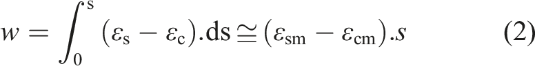
Prediction of the crack width.
Parametric study
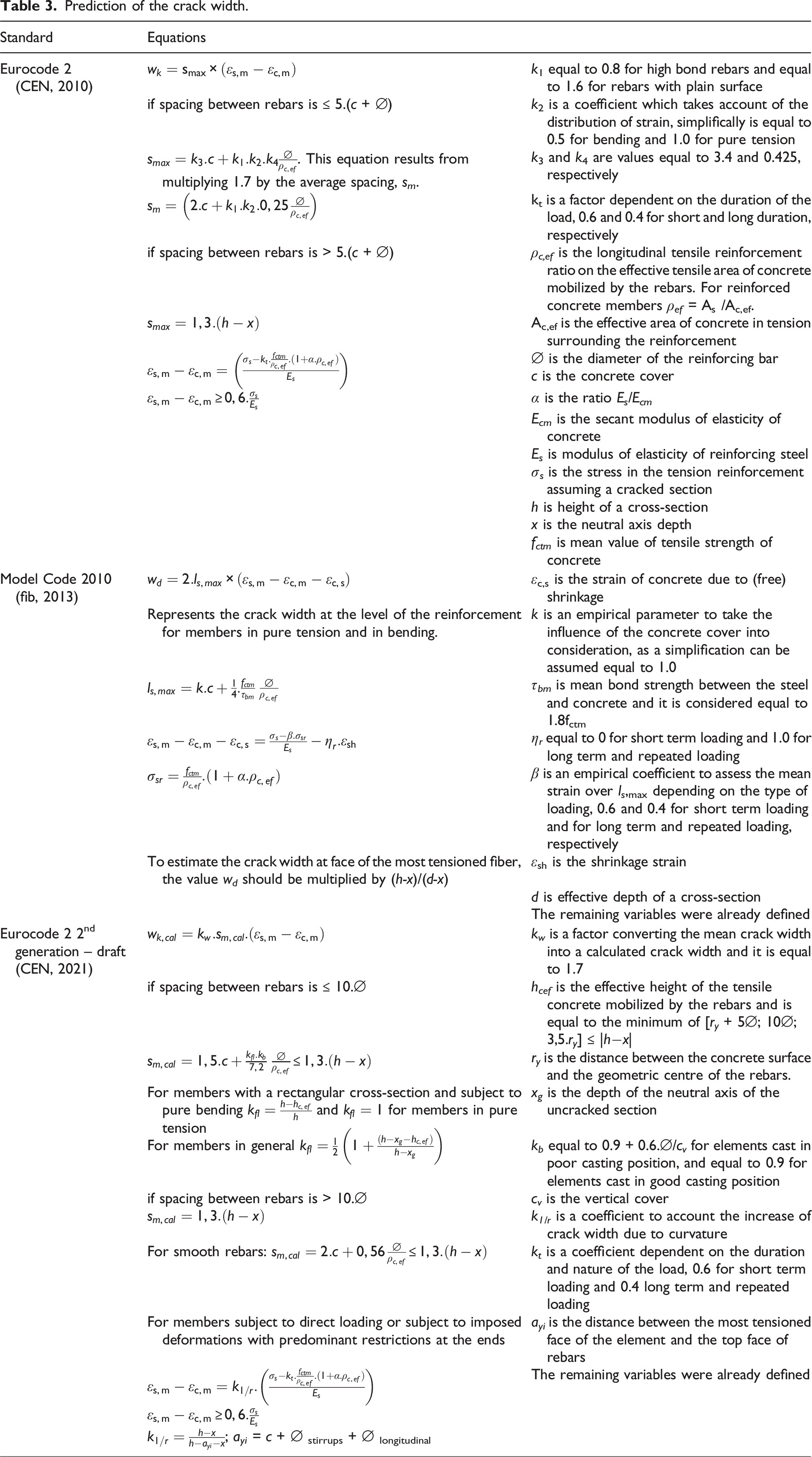
To achieve the defined goals, a parametric study was carried out on a simple hyperstatic structure considering where the following variables: (i) 5 levels of moment redistribution, 0%, 10%, 20%, 30%, 40% and 50%, resulting in five different moment distributions (Figure 3); (ii) 4 types of steel regarding strength, namely, fyk equal to 400, 500, 600 and 700 MPa, were used in the design of the beam to guarantee the proper flexural strength; (iii) 3 different ratios between the loads corresponding to service conditions (qELS) and loads used on the verifications of the Ultimate Limit States (qELU) were considered, namely, to 0.55, 0.65 and 0.75; (iv) 3 different models for predicting the cracks width were used, particularly the models presented in Eurocode 2 (CEN, 2010), Model Code 2010 (fib, 2013) and Eurocode 2 2nd generation draft (CEN, 2021). Diagrams of bending moment considering a linear elastic analysis and moment redistribution at intermediate support.
In order to carry out this parametric study, it was necessary to assume certain conditions. It was considered a continuous symmetrical beam with two spans with 6 m, subjected to a uniformly distributed load of 80 kN/m (Pmax), a cross-section of 0.30 × 0.55 m2 and concrete of class C30/37. The uniformly distributed load of 80 kN/m results from the fundamental combination of actions used for verifying the Ultimate Limit States of resistance. This load assumes that slabs are supported on the beam, with loads typically considered in standard structures. The corresponding bending moment diagrams are shown in Figure 3, where only the right span is displayed due to the structure’s symmetry. The moment at the intermediate support varied between −360 and −180 kN.m, while the maximum positive moment ranged from 202.5 to 276 kN.m.
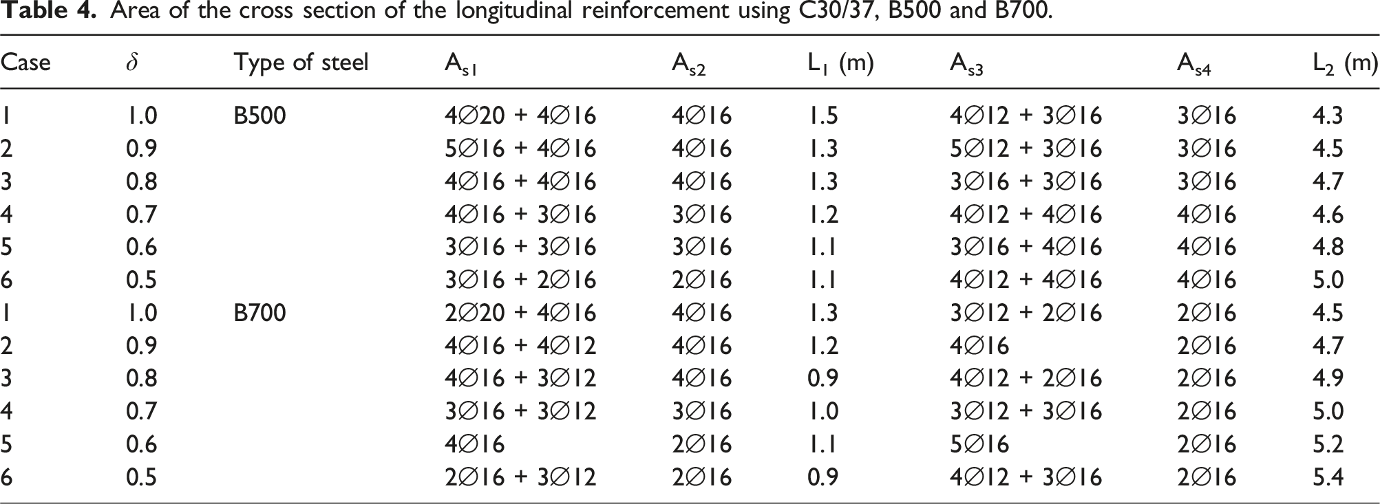
Based on the distribution of internal forces, the longitudinal reinforcement was defined, as shown schematically in Figure 4 and exemplified in Table 4 for the cases using B500 and B700 steels. The crack width was then determined for the three load levels listed, applying the three different prediction models mentioned above. In this study, real solutions for the longitudinal reinforcement were used, which, in certain cases, required slight adjustments to the rebar diameter. These adjustments marginally affected the calculation of crack spacing and, consequently, the crack width. When a mixture of rebars was used, the equivalent diameter was used in the calculations, mitigating the effect of using rebars with different diameters. The crack width determined at the intermediate support was correlated with the moment redistribution for each situation, and all results are summarized in Figure 5. Distribution of longitudinal reinforcement. Area of the cross section of the longitudinal reinforcement using C30/37, B500 and B700. Relation between the redistribution coefficient and the crack width under service conditions: (a) f
yk
= 400 MPa; (b) f
yk
= 500 MPa; (c) f
yk
= 600 MPa; (d) f
yk
= 700 MPa.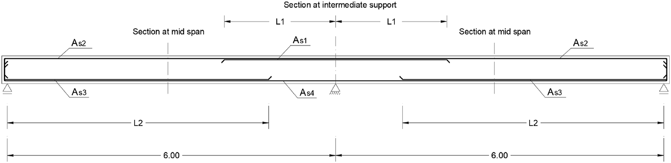
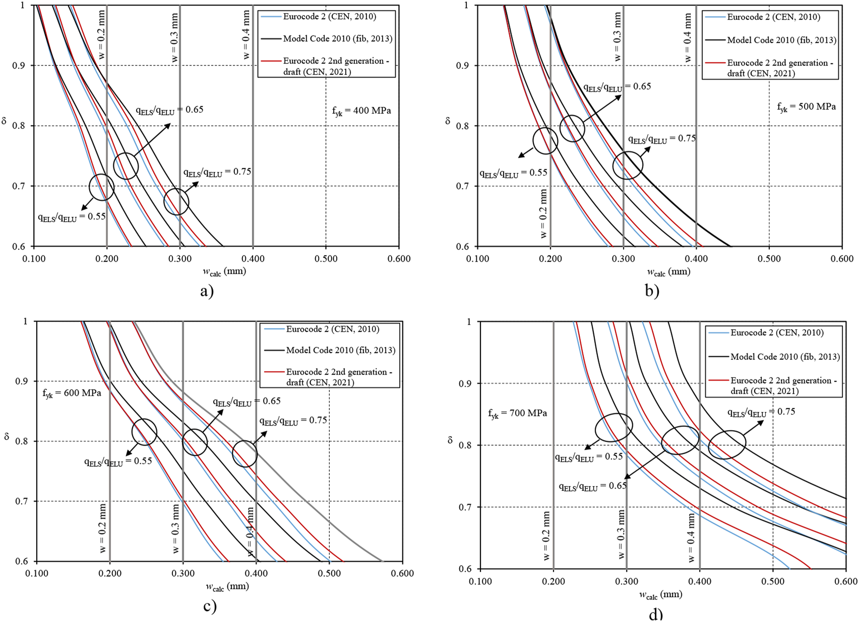
Using steel with f yk equal to 400 MPa and limiting the crack width to 0.2 mm, it can be seen that the moment redistribution should not exceed 20% for cases where the qELS/qELU ratio is equal to 0.65, and should not exceed 15% for cases where the qELS/qELU ratio is equal to 0.75. If the maximum crack width allowed in service conditions is increased to 0.3 mm, then the moment redistribution can be greater, and can exceed 30% for all qELS/qELU considered, although in these cases it is necessary to verify that the steel reinforcement does not reach the yield strength in service conditions.
Using steel with f yk equal to 500 MPa further limits the redistribution of moments. When the crack width is limited to 0.2 mm, the moment redistribution should not exceed 25% in cases where qELS/qELU is equal to 0.55 and for higher ratios the moment redistribution is even more limited, less than 15% for qELS/qELU equal to 0.65 and almost no moment redistribution should be performed when qELS/qELU is equal to 0.75. If the crack width is limited to 0.3 mm, then the maximum possible moment redistribution increases, but should be less than 30% for higher values of qELS/qELU ratios. In the most aggressive environments, where it is necessary to limit the crack width to 0.2 mm, steels with f yk equal to 700 MPa cannot be used and steels with f yk equal to 600 MPa can only be perform a moment redistribution around 10% and for low ratios of qELS/qELU, if the qELS/qELU increases to 0.75 then this type of steel cannot also be used.
When cracks widths are limited to 0.3 mm and qELS/qELU is equal to 0.65, the moment redistribution must be less than 20% and less than 10% for steels with f yk equal to 600 MPa and 700 MPa, respectively. Increasing the qELS/qELU ratio constrains even more the maximum possible moment redistribution. In certain cases, as qELS/qELU equal to 0.75, is not possible to use the steel with f yk equal 700 MPa, even without moment redistribution. The use of high strength steels significantly limits the moment redistribution, particularly in situations with high loads at service conditions. It can therefore be concluded that it is only possible to exploit the full strength and ductility of the high strength steels, such as f yk equal to 700 MPa, if structures are located in less aggressive environments, where the crack width is limited to 0.3 or 0.4 mm.
Summarizing, it was found that as higher is the strength of the reinforcing steels and the qELS/qELU ratio, and lower is the limit for crack widths, the lower is the maximum possible moment redistribution that can be used in ULS analysis, meaning that on those cases the design of the longitudinal reinforcement is certainly conditioned by the verification required at service conditions, particularly, by the limitation of the maximum crack width. In some cases, the moment redistribution defined in the main codes, as 20 and 30%, depending on the ductility class of steels, is not restrictive enough to ensure that the maximum crack width under service conditions is not exceeded. These trends are more evident in Figure 6, where the moment redistribution is related with the strength of steel, the qELS/qELU ratio and the crack width predicted using only the Eurocode 2 model (CEN, 2021). Only the version foreseen in the 2nd generation of EC2-1 was used to establish this relation because it is an update of the previous models. Relations between the moment redistribution coefficient and the crack width under service conditions considering the various steel strengths: (a) qELS/qELU = 0.55; (b) qELS/qELU = 0.65; (c) qELS/qELU = 0.75.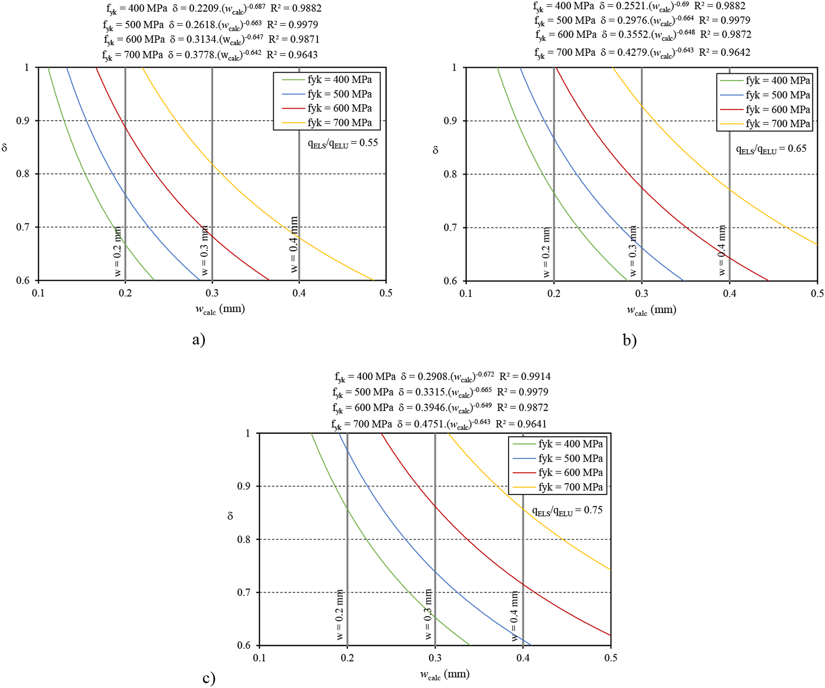
Usually, the design of reinforced concrete members begins with the verifications for the ULS, during this process the structural engineer selects the value δ within the limits imposed by codes. After calculating the required longitudinal reinforcement, several verifications must be performed: i) ensure that the sections at the supports have enough ductility to accommodate the assumed moment redistribution; ii) verify the behavior under service conditions, particularly the width of cracks. If these checks are not satisfied, the initially assumed value of δ may need to be adjusted. The design process is iterative, and to minimize the need for multiple iterations, equation (3) is proposed. This empirical equation can be a practical tool for determining the maximum possible moment redistribution, δ, considering all the variables identified above.
Equation (3) was developed based on all the results obtained and the equations presented in Figure 6, which exhibit high coefficients of determination (R2). The average error between the actual redistribution coefficient used and the one predicted by equation (3) was below 6% for all possible combinations. This approach provides a quick and efficient way to predict the maximum allowable redistribution for ULS, taking into account all key factors. As a result, it enables the identification of a structural solution that complies not only with ULS but also with SLS requirements.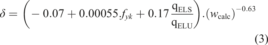
Overall behavior of the beam
To understand all effects of the moment redistribution, it is important to analyze the behavior of the beam, not only in the support section, but also in the span sections, in terms of cracking and deformation. It is also crucial analyze the real evolution of the moment distribution along the beam axis for different load levels to understand the influence of the relative stiffness of the sections in State II (after cracking). This is particularly relevant because the linear analysis with limited moment redistribution is only valid for Ultimate Limit States (ULS) and it is based on the Static or Lower limit theorem of the Plasticity theory, i.e. the internal forces must be in balance with the external loads and, of course, the stresses generated must also meet the strength criteria of the materials. It is therefore important to know the real moment distribution on service conditions, at an intermediate stage of loading, bearing in mind that the sections are already cracked, so the different longitudinal reinforcement ratios along the beam axis will play a fundamental role. It should be remembered that the main codes states that linear elastic analysis is applicable for Serviceability Limit States (SLS) checks, even if the critical sections are already cracked.
To achieve this goal, a non-linear analysis was carried out using the moment-curvature relation of each section, determined using the average values of the material properties and taking into account the effect of concrete between cracks, the so-called ‘tension stiffening effect’ (Figure 7). The tension stiffening effect was determined using the Model Code 2010 model (CEN, 2021) to define the average deformation of the tensile region, including the reinforcement and the concrete between cracks. It should be noted that the effect of creep was not considered in this analysis and the areas of the cross section of the reinforcement considered in each section were effectively the minimum areas required to check the safety of the flexural strength at ULS, considering the different distributions of moments, without and with redistribution. An incremental analysis was then carried out using the Evals software (Ferreira, 2023), fulfilling the boundary conditions, being possible to determine the distribution of moments and curvatures at different loading phases and along the beam axis, as well as the stresses in materials and vertical displacements (Ferreira et al., 2017, 2021). Nonlinear relation between moment and curvature, for different moment redistributions, without moment redistribution (left) and considering a degree of moment redistribution equal to 0.6 (right).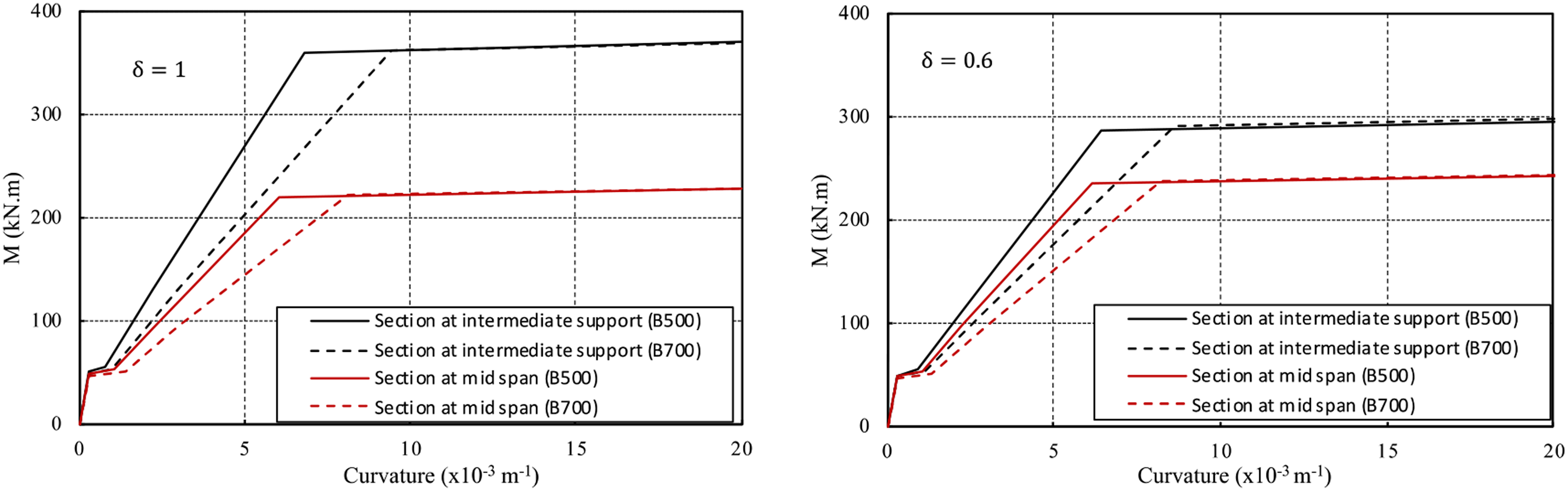
In this analysis, 6 different scenarios were considered changing the following variables: i) the strength of steels, B500 and B700; and ii) 3 different levels of moment redistribution, δ equal to 1, 0.8 and 0.6. Figure 7 clearly shows the difference of curvature of the sections in state II when steels of different strengths are used. This difference is due to the difference of equivalent flexural stiffness, EIeq, because in state II the flexural stiffness is highly dependent on the area of the longitudinal reinforcement. Therefore, it is expected that the moment distribution along the beam axis vary with loading and will be different from that assumed in a linear elastic analysis.
Considering the ‘real’ flexural stiffness corresponding to each loading phase, which varies along the beam axis according to the actual distribution of longitudinal reinforcements, the distribution of the internal forces differs from that expected and calculated using a linear elastic analysis. To better understand this difference at critical sections throughout the loading process, two types of graphs were defined: i) the relation between the moment at support section and the moment at the span section with the P/Pmax ratio (in this case Pmax is equal to 80 kN.m), see Figure 8; ii) the relation between the 1-M/Mel and the P/Pmax ratio, where M is the actual moment at the section and Mel is moment expected by linear elastic analysis, see Figure 9. The load range corresponding to the service conditions is also identified. Relation between the moments and the load: (a) f
yk
= 500 MPa; (b) f
yk
= 700 MPa. Relation between the 1−M/Mel and the load (using the average strengths): (a) f
yk
= 500 MPa; (b) f
yk
= 700 MPa.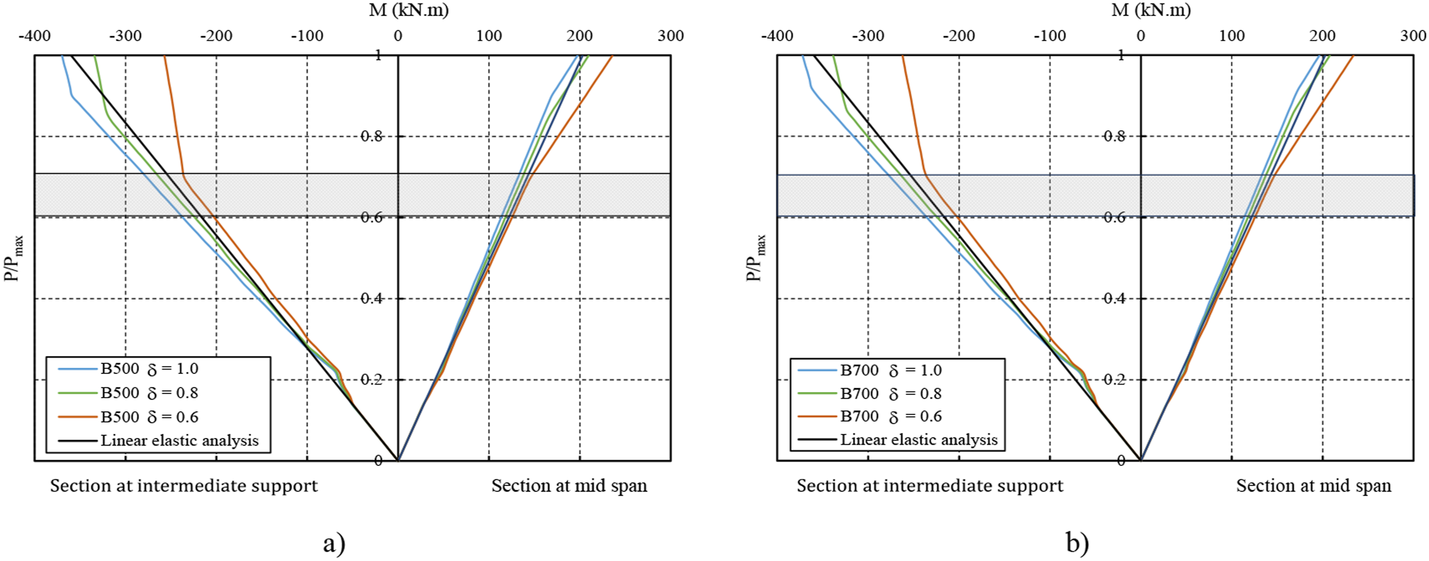
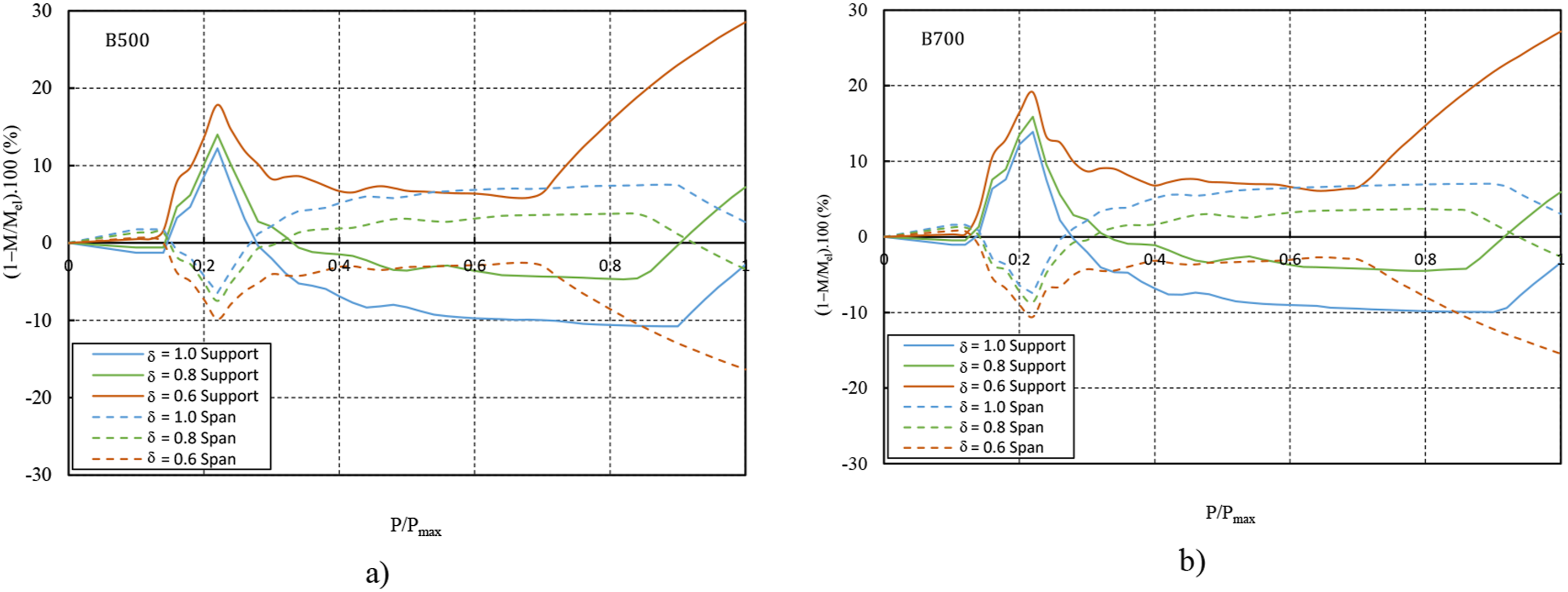
It can be observed that even under service conditions, the moments at support and span sections deviate slightly from the values predicted by linear elastic analysis. If a design is carried out without moment redistribution or with a 20% redistribution (δ = 0.8), the negative moments increase more than initially expected, by approximately 10% when δ = 1 and 4% when δ = 0.8. This means that the stresses in the upper reinforcement will be higher than anticipated. In contrast, the moments in the span section are slightly lower than those predicted by linear elastic analysis. If the longitudinal reinforcement is calculated based on a higher moment redistribution (δ = 0.6), the opposite occurs: under service conditions, the moment at the support section is approximately 7% lower than that predicted by linear elastic analysis. The internal distribution of moments is influenced by the relative stiffness of the support and span sections in the cracked state. Even with a moment redistribution of up to 0.8, the support section retains greater stiffness than the span sections, resulting in higher moments than initially expected. It is only when δ is equal to 0.6 that the span section has more tensile reinforcement than the support section, reversing the situation. There are no significant differences in the moments distribution in service conditions using B500 steel or high strength steel B700.
The graphs in Figures 8 and 9 were produced using the average values for material properties. However, the calculation of the longitudinal reinforcement was performed using the standard methodology, which incorporates safety coefficients for material strength. For this reason, the moment redistribution when P equals Pmax does not match the redistribution used to calculate the longitudinal reinforcement (Figure 9). If the same analysis is conducted using the safety coefficients (see Figure 10), the moment redistribution when the structure reaches its maximum load exactly matches the initially assumed moment distribution. Relation between the moment redistribution and the load (using the design strengths) for f
yk
= 500 MPa: (a) relation between moment and load; (b) the relation between 1−M/Mel and the P/Pmax ratio.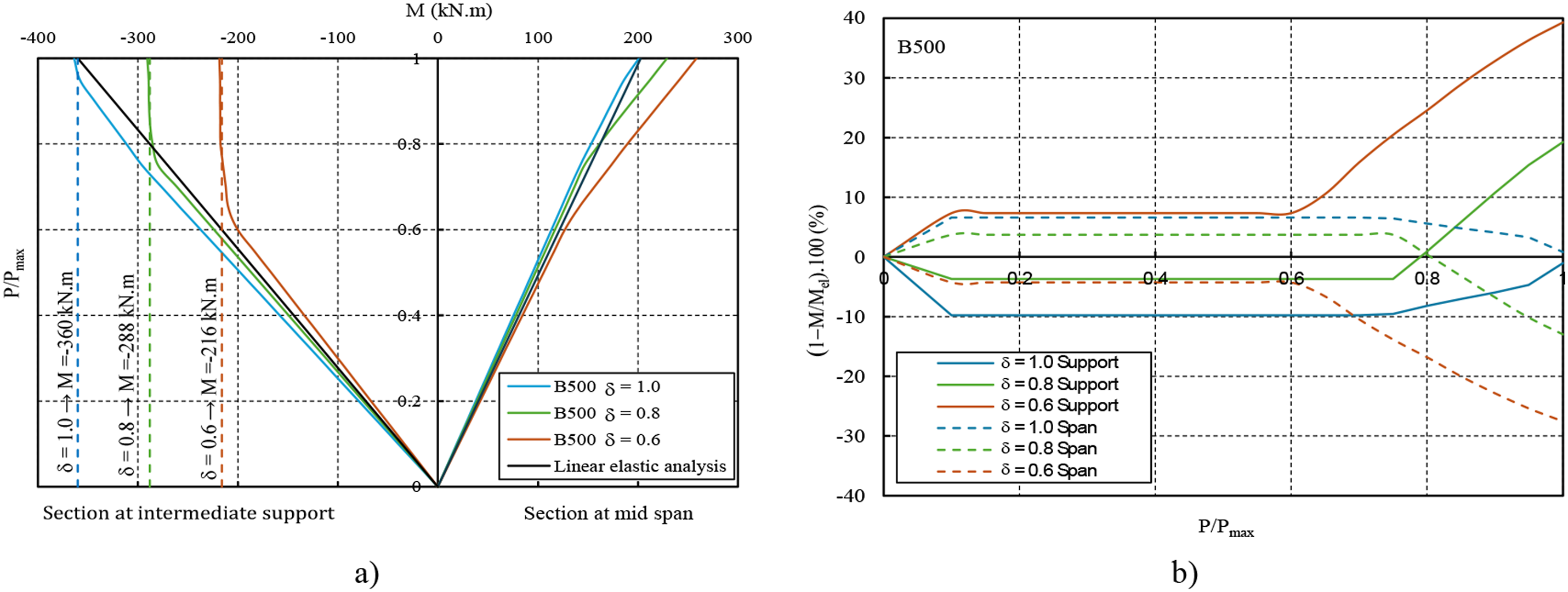
Figure 11 shows how the flexural stiffness varies along the beam axis, showing significantly higher values in non-cracked zones, sections where the moment is less than the cracking moment. To highlight the difference compared to linear elastic analysis, the stiffness of sections in State I (green line, EIc) is also presented, calculated based solely on the concrete properties and geometric dimensions. Flexural stiffness along the beam axis: (a) two load stages and two types of steel; (b) three load stages for B500.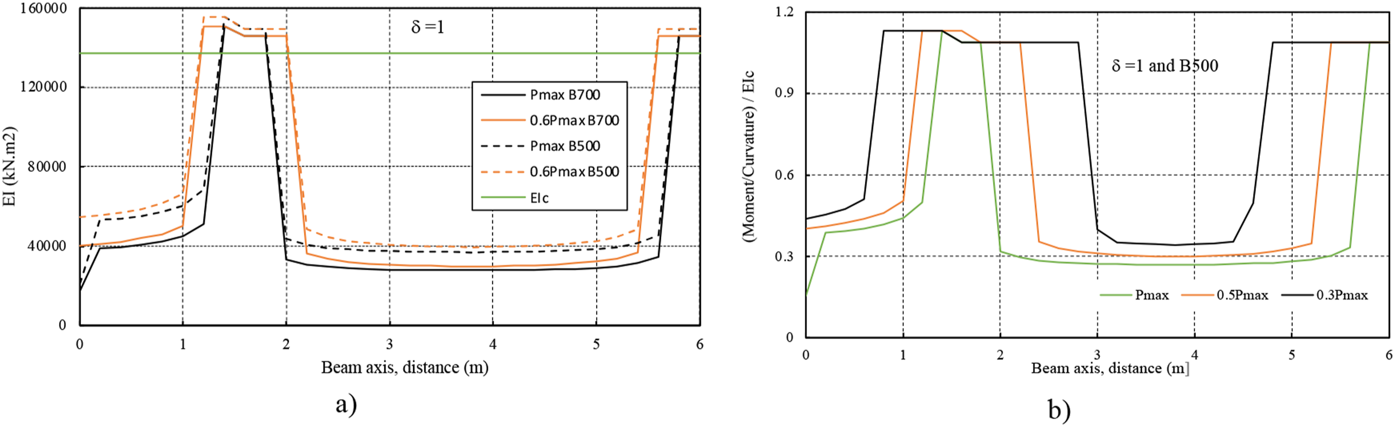
The considerations regarding the prediction of moments in critical sections under service conditions are important because they directly influence the stresses in the tensile reinforcement, which, in turn, affect the crack width. Figure 12 demonstrates the evolution of stress in the tensile reinforcement at the support and span sections as the load increases, based on the moment distribution predicted using the effective stiffness of the sections along the beam axis in a non-linear analysis. Evolution of the tensile stress in the reinforcement with the load: (a) section at intermediate support; (b) section at mid span.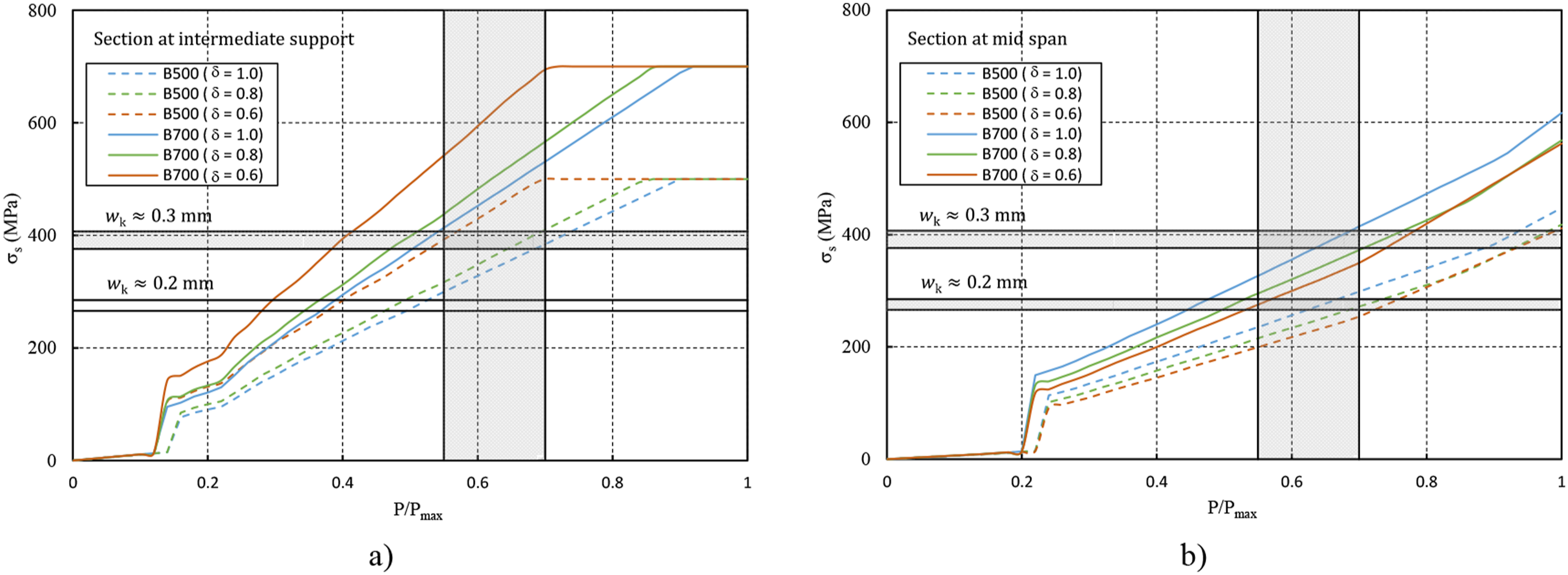
Figure 12 clearly illustrates the abrupt increase in stress in the reinforcement when concrete begins to crack, corresponding to the transfer of tensile forces from the concrete to the reinforcement. Analyzing the tensile stress in the support section, it can be concluded that high-strength steels cannot be used without exceeding the established crack width limits unless the service conditions correspond to a very low load level (P/Pmax < 0.6). B500 steel, however, can be used even with a 20% moment redistribution in environments requiring a crack width of only 0.3 mm. If the crack width limitation is more demanding and must be less than 0.2 mm, B500 steel can only be used when the service conditions correspond to a stress level of P/Pmax ≅ 0.5.
It is important to highlight that this prediction of tensile reinforcement stress considers the ‘real’ distribution of moments, thereby accounting for the stress increase resulting from the greater relative stiffness of the support section compared to other sections. If the crack width limit is not a constraint and can exceed 0.3 mm (e.g., in typical buildings the upper side of sections near supports is in protected environments with multiple layers of protection, a leveling layer, and cladding materials), B700 steel can be used even in scenarios involving moment redistribution.
In span sections, the tensile stresses in the reinforcement are not as high, so it is, therefore, easier to comply with the crack width check under service conditions. For these sections the crack width compliance should be more demanding than for sections near supports, not only for aesthetic reasons but also for durability reasons. Both B500 and B700 steels can be used in situations where the maximum crack width is 0.3 mm, even when moment redistribution is considered. However, to meet the requirement of a crack width less than or equal to 0.2 mm, B700 cannot be used, because the tensile stress in the reinforcement under service conditions becomes excessively high.
The variation of curvature along the beam axis for different load levels is shown in Figure 13. Even for a design based on a linear elastic analysis without moment redistribution, the reinforcement in the support section has to yield in order to reach the maximum load predicted by the calculation (Figure 13(a) and (c), this is valid for both B500 and B700 steels), i.e. the critical sections have to develop a certain plastic rotation. This need for a certain level of ductility arises because reinforced concrete exhibits non-linear behavior before the reinforcement reaches its yield strength, leading to a moment distribution that differs from that predicted by linear elastic analysis. In State II (cracked state), variations in section stiffness along the beam axis cause some sections to yield earlier than others. For the remaining sections to also reach their design moment strength and for the beam to achieve its expected load capacity, plastic rotation must occur in the support sections. If the reinforcement design is based on an analysis with moment redistribution, the ductility requirement for critical sections becomes even more demanding, as proven in Figure 13(b) and (d). In such cases, a certain amount of plastic rotation in the sections near the supports is necessary even to reach 90% of the expected load. Evolution of the curvature along the beam axis: (a) beam designed with B500 steel and δ = 1; (b) beam designed with B500 steel and δ = 0.8; (c) beam designed with B700 steel and δ = 1; (d) beam designed with B700 steel and δ = 0.8; (e) differences of curvatures at Pmax considering different steels and moments redistribution; (f) differences of curvatures at 0.6Pmax considering different steels and moments redistribution. 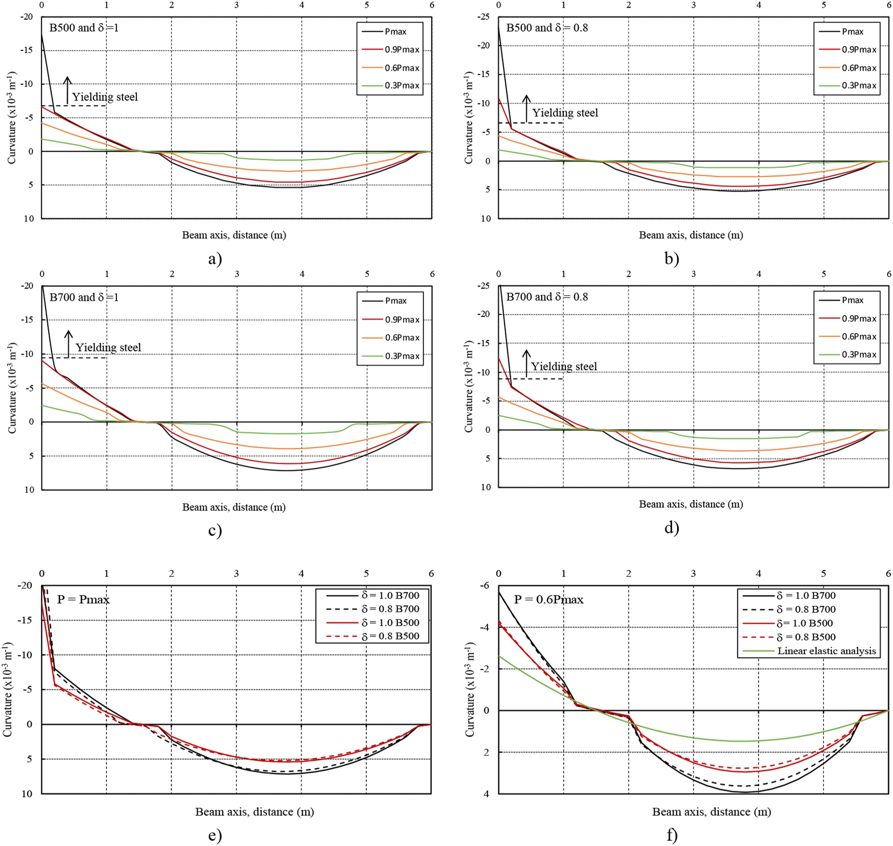
At maximum load, the curvature along the beam axis differs slightly between beams designed with B500 and B700 steels. But under service conditions, the difference is more pronounced and significantly deviates from that predicted by linear elastic analysis. The beam designed with B500 steel exhibits smaller curvatures because it requires larger areas of reinforcement compared to the beam designed with B700 steel, resulting in greater flexural stiffness. This is particularly relevant in State II (cracked state). The design based on moment redistribution analysis does not significantly alter the curvature variation along the beam axis. As expected, the curvature is smaller in the span sections, as this region of the beam has an increased area of longitudinal tensile reinforcement compared to the design without moment redistribution.
Figure 14 shows the evolution of vertical displacement in the beam span as the load increases, for scenarios without (δ = 1.0) and with moment redistribution (δ = 0.8 and δ = 0.6). The scenario without moment redistribution serves as a reference in this comparative analysis. Under service conditions, typically corresponding to a load level of around 0.6 or 0.7Pmax, the vertical displacements are not significantly affected by moment redistribution. At this load level, the vertical displacements range between 7 and 8.4 mm, and as shown in Figure 14, the displacements of beams designed with and without moment redistribution are quite similar within this range. However, closer to the maximum load, the vertical displacements are greater when there is no moment redistribution. This is likely because designing the beam for this scenario requires less longitudinal reinforcement in the span, resulting in reduced flexural stiffness in this region. It should also be emphasized that these vertical displacements do not account for the influence of concrete creep, which, as is well known, is an important factor to consider under long-term loading. The graph in Figure 14 is also significant because it demonstrates that the differences in cracking and flexural stiffness, resulting from different longitudinal reinforcement designs, do not significantly affect the vertical displacement values. Vertical displacement at span with and without moment redistribution.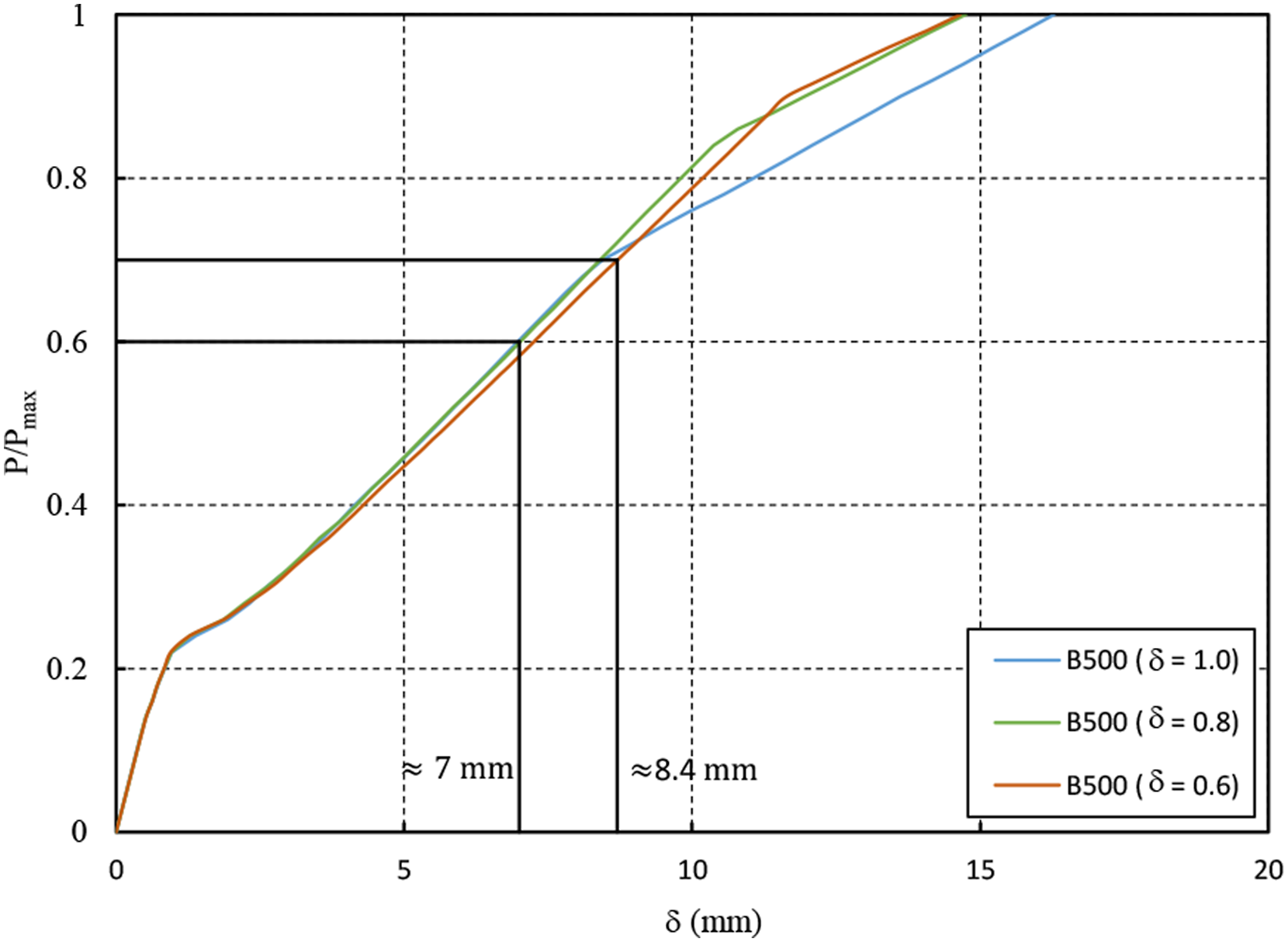
Conclusions
Based on the study carried out the following conclusions can be drawn: • Maximum moment redistribution and crack width limitations – The maximum moment redistribution in a ULS analysis is greatly influenced by the limitation of the maximum crack width under service conditions. For structures in environments requiring a maximum crack width of 0.2 mm, moment redistribution is constrained not by the ductility of the support sections but by crack control requirements. • Importance of the qSLS/qULS ratio – The qSLS/qULS ratio plays a critical role in verifying SLS conditions. It is evident that the higher the qSLS/qULS ratio, the lower the allowable maximum moment redistribution. • Restrictions with current steels – Even when current steels are used, the maximum moment redistribution can be more restrictive than the limits recommended by major codes such as Eurocode 2 and fib Model Code. This is particularly true when the qSLS/qULS ratio is 0.65 or higher and when crack width control is demanding (e.g., wmax = 0.2 mm). For instance, with a qSLS/qULS ratio of 0.75, only 15% and 5% moment redistribution is permissible when using B400 and B500 steels, respectively. • Limitations with high-strength steels with moment redistribution – When high-strength steels are used, moment redistribution is highly restricted and is only feasible for specific exposure classes. In other words, the maximum moment redistribution is far more constrained by crack width limitations under service conditions compared to ordinary steels. For example, when using steel with a strength of 700 MPa, no moment redistribution is possible if the maximum crack width is limited to 0.2 mm, and it is severely limited if the maximum crack width is 0.3 mm. Similarly, B600 steel allows for very limited moment redistribution (below 10% or none) when the maximum crack width is 0.2 mm, depending on the qSLS/qULS ratio. • Limitations with high-strength steels without moment redistribution – Even without moment redistribution, B700 steel can only be fully utilized in very specific situations. This is because meeting crack width constraints requires additional longitudinal reinforcement to reduce steel stress under service conditions. As a result, when high-strength steels are used, serviceability requirements become a more critical design factor than strength considerations at the Ultimate Limit State (ULS). • Empirical equation for maximum redistribution – An empirical equation is proposed to quickly predict the maximum allowable moment redistribution at ULS. This equation considers not only the maximum permissible crack width and the qSLS/qULS ratio but also the steel strength. This tool can be useful for pre-designing and carrying out design procedures more efficiently. • Distribution of internal forces for SLS analysis – Main structural codes recommend predicting internal forces using linear elastic analysis for verifications at SLS, regardless of whether moment redistribution is applied in the ULS analysis. However, when a more rigorous analysis is conducted to determine the actual moment distribution, it becomes evident that the moment distribution under service conditions deviates from that predicted by linear elastic analysis. This discrepancy can impact crack width predictions. • Importance of ductility – Ductility is a critical requirement because, even when a beam is designed based on a linear elastic analysis without moment redistribution, the reinforcement at the support section must yield for the beam to achieve its predicted load capacity. This ductility requirement becomes even more demanding when moment redistribution is considered. • Vertical displacements and moment redistribution – Vertical displacements are not significantly affected by moment redistribution or the type of steel used.
The combination of high-strength steels with high-performance concrete can be an optimal solution for structures with high technical requirements and constraints. High-strength concrete is generally more brittle than ordinary concrete, but if the beams are designed using low ratios of longitudinal tensile reinforcement there is no loss of ductility and high-strength steels can be useful in this respect. In future studies it will be important to analyze in detail the consequences in terms of structural performance when these two materials are used simultaneously.
Footnotes
Declaration of Conflicting Interests
The author(s) declared no potential conflicts of interest with respect to the research, authorship, and/or publication of this article.
Funding
The author(s) disclosed receipt of the following financial support for the research, authorship, and/or publication of this article: The first author acknowledges the support of FCT - Fundação para a Ciência e a Tecnologia, through the project UIDB/04625/2020, that finances the author’ research center, CERIS - Civil Engineering Research and Innovation for Sustainability.