
Abstract
To improve the modelling and the computation efficiency, homogenisation techniques have been applied to conventional masonry structures composed of brick units and mortar. However, for dry-stacking interlocking brick structure, which is gaining growing attention due to its advantages, no derivation of its homogenisation mechanical properties is yet available, thus the design analysis of interlocking brick structure is still complex. In this paper, a representative volume element (RVE) is extracted from interlocking brick walls on the basis of periodic construction patterns. Detailed numerical modelling of the RVE and simulations are carried out considering the nonlinear material properties and different stress states. The equivalent material properties of the RVE are derived from the numerical simulation results. Compressive and tensile damage scalars according to the theory of continuum damage mechanics are used to analyse the hardening behaviour, the softening behaviour, and the failure of the RVE. To verify the obtained equivalent material properties, interlocking brick walls modelled with the RVE element and the homogenised material properties subjected to the uniaxial compressive loading and the combined compression-shear loading are analysed. The results are compared with those obtained from the detailed modelling of the interlocking brick wall. The accuracy and the efficiency of using the derived equivalent material properties in modelling the interlocking brick wall are demonstrated.
Keywords
Introduction
Masonry construction is one of the most common construction formats in the world particularly for low-rise buildings. Different brick materials (clay, concrete, rammed earth, etc.), various construction methods (thin bed, epoxy glue, dry-stacking, etc.), and miscellaneous block types (plain and interlocking) have been developed over the past decades to improve the structural performance and construction efficiency. Among them, interlocking brick structures with dry-stacking construction method are attracting growing attention because it offers certain advantages, such as reduced labour cost and low requirements on labour skills (Ramamurthy and Kunhanandan Nambiar, 2004; Saari et al., 2021). Moreover, the interlocking mechanism could provide additional shear resistance, hence changing the performance of the dry-stacking interlocking brick structure under different loading conditions (Casapulla et al., 2019; Dyskin et al., 2012). To facilitate their engineering applications, accurate and efficient determination of the mechanical properties, structural responses, and failure mechanisms of dry-stacking interlocking brick structures are essential.
Experimental studies have been extensively employed to study the behaviour of both conventionally mortar-bonded and mortarless interlocking masonry structures, such as in References (Gumaste et al., 2007; Sturm et al., 2015). Since experimental methods are very time-consuming and costly, numerical modelling methods, for example, discrete element method (DEM) and finite element method (FEM), have been widely used. Methods for modelling masonry structures using FEM can be divided into three categories (Zhang et al., 2017): (i) micro-modelling method (direct simulation), where brick units, mortar, and brick/mortar interfaces are modelled in detail. It enables the observation of localised damage of brick, mortar and joint (Lourenço, 1997; Rekik and Lebon, 2012; Sacco and Toti, 2010). Since this method always involves a large number of elements, it is very time-consuming and therefore not well applicable to large-scale structures; (ii) simplified micro-modelling method, where the brick units are simulated as continuum elements while mortar joints as well as brick/mortar interfaces are lumped and modelled using surface contact algorithms or interface elements (Alforno et al., 2021; Casolo and Milani, 2013; Gambarotta and Lagomarsino, 1997; Silva et al., 2017), for the bricks are usually much stiffer than the mortar and joints (Anand and Ramamurthy, 1999; ASTM International, 2024). Comparing with the detailed micro-modelling method, the simplified method is less computational resource demanding; (iii) macro-modelling method, which is regarded as a transition from the micro-scale detailed material modelling to structural-scale modelling according to the homogenisation theory. Many homogenisation techniques are applied to model masonry structures due to their periodic layouts and properties. For example, representative volume elements (RVE) are derived to model bricks and mortar with joints for derivation of the homogenised macro material properties of masonry structures (Yang et al., 2012).
A series of studies have been conducted regarding the derivation of RVEs and homogenisation of masonry. Pande et al. (1989) were probably the first group of researchers who attempted to homogenise a masonry structure, and proposed a two-step homogenisation scheme: firstly, the masonry bricks and head joints are homogenised in the horizontal direction. Then, the RVE is further homogenised in the vertical direction considering the bed joints. Choudhury et al. (2020) demonstrated that the homogenisation method could reasonably predict the global response and crack patterns of masonry shear walls with openings. Gabor et al. (2006) applied this technique to obtain the elastic properties of the homogenised RVE, while Ma et al. (2001) derived the two-dimensional RVE for masonry structures with nonlinear inelastic constitutive properties, including the strength envelope and the damage rule. Wei and Hao (2009) and Peng et al. (2018) furthered the consideration of inelastic properties of the homogenised RVE using a Drucker-Prager (DP) strength envelope. Recently, more advanced techniques and theories have been utilised for homogenisation in more complex scenarios. Castori (2024) used Digital Image Processing (DIP) and test windows to homogenise irregular masonry and model its elastic behaviour. Hermans et al. (2024) expanded the usage of the DIP and test window method to homogenise irregular masonry and considered its nonlinear behaviour. To simplify the homogenisation process, Meftah et al. (2024) neglected the role of head joints and compensated for the neglection by a precise damage localisation and shear strain prediction using the Higher Order Shear Deformable Theory (HSDT).
It should be noted that RVEs and homogenisation techniques developed in previous studies are based on conventional masonry structures (Bertolesi et al., 2016; Milani and Bertolesi, 2017), where masonry units are bonded by mortar, which gives the masonry certain tensile strength. In comparison, dry-stacking interlocking masonry structures are discrete systems; little tensile strength exists in the direction of dry-stacking (usually being the vertical direction). Thus, the homogenisation methods suitable for conventional masonry may not be used directly in the context of dry-stacking interlocking masonry. As far as the authors know, studies regarding the homogenisation of dry-stacking interlocking masonry systems are quite limited hitherto. Brocato (2018) conducted theoretical deduction to homogenise dry-stacking topological interlocking masonry systems composed of convex polyhedrons and considered the system as the superposition of two continua with microstructure, that is, the continuum of rigid masonry units, and the continuum of the contacting surfaces between the masonry units, hereby yielding a complete set of motion equations as well as constitutive laws. Sahli et al. (2022) studied the homogenisation of dry-stacked Hydraform blocks (a type of interlocking blocks with small interlocking keys and can slide on each other in the in-plane direction) and extracted the homogenised constitutive relation from the derived RVE. A homogenised wall subjected to harmonic base excitation was then modelled and validated against the corresponding test results by Elvin and Uzoegbo (2011), demonstrating the suitability of their homogenised model in the application of seismic studies.
It is to note that the interlocking bricks used in the above two studies are either convex (without interlocking keys) or featured with small keys that can interlock only in the out-of-plane direction. In contrast, dry-stacking masonry structures made of interlocking bricks with large keys that can in both in-plane and out-of-plane directions has relatively strong shear resistance and large contact areas between bricks (Xie et al., 2022, 2023, 2024), which make their behaviour differ from that of the dry-stacking masonry studied in (Brocato, 2018; Sahli et al., 2022). Hence, the homogenisation methods put forward in the previous studies may not be adaptable to the ones with large keys and interlocked in both in-plane and out-of-plane directions.
The homogenisation of dry-stacking masonry composed of interlocking bricks with relatively large shear keys and interlocked in both in-plane and out-of-plane directions have only been studied by the authors in a previous research (Zhang et al., 2024). In that study, the homogenisation of dry-stacked masonry structures composed of Tetraloc interlocking bricks (a type of interlocking bricks featured with large shear keys and interlocked in both in-plane and out-of-plane directions) was conducted. The strain rate effect of the homogenised model under dynamic loading was discussed in detail, and the applicability of the model was validated against the test results of a wall subjected to impact loading. Nevertheless, static responses as well as size effect have not been delved into in that research.
By contrast, the study in this paper focuses on the generation of the homogenised model of dry-stacking interlocking masonry made of Tetraloc bricks under static loading. The elastic behaviour is extracted from the derived RVE under different static loading conditions; the nonlinear properties are characterised using the Concrete Damaged Plasticity (CDP) model. The accuracy of the generated RVE with the derived equivalent material properties in representing the performances of interlocking brick structures is verified through comparisons with the simulation results of a detailed numerical model of an interlocking brick wall subjected to uniaxial compression and combined shear-compression. The size effect of the RVE is also examined. It should be noted that although this study focuses only on a particular type of interlocking bricks — Tetraloc bricks, the methodology, however, can be applied to homogenise other types of dry-stacking interlocking masonry structures made of interlocking bricks with relatively large keys and interlocked in both in-plane and out-of-plane directions.
Methodology
To initiate the homogenisation analysis, a suitable RVE needs to be defined. Specifically, an RVE of interlocking brick structure should satisfy the following requirements: (i) the RVE includes an adequate quantity of material phases; (ii) the whole structure can be formed by continuous and periodic distributions of RVEs; and (iii) the RVE is small enough but satisfies the above-mentioned requirements (Wei and Hao, 2009).
In this study, the RVE is comprised of the Tetraloc interlocking bricks of 200 mm × 100 mm × 180 mm (length × thickness × height) with large protruded mortise and tenon (35 mm length × 35 mm thickness × 30 mm height) (see Figure 1). Such a shape and geometry have been proved to give optimised compressive and shear properties (Shi et al., 2021a, 2021b, 2023). In the numerical simulations conducted in this study, the round holes shown in Figure 1(d) are simplified to square holes with side lengths equal to the diameter of the round holes. Previous studies by the authors on the same type of interlocking bricks have demonstrated that this simplification has minimal influence on the simulation results for interlocking brick assemblies under both static and dynamic loading conditions (Shi et al., 2021a, 2021b, 2023; Xie et al., 2020, 2022, 2023, 2024; Zhang et al., 2024). Configuration of the studied interlocking brick (unit: mm). (a) Front view, (b) Back view, (c) Left view, (d) Top view, (e) Isometric view.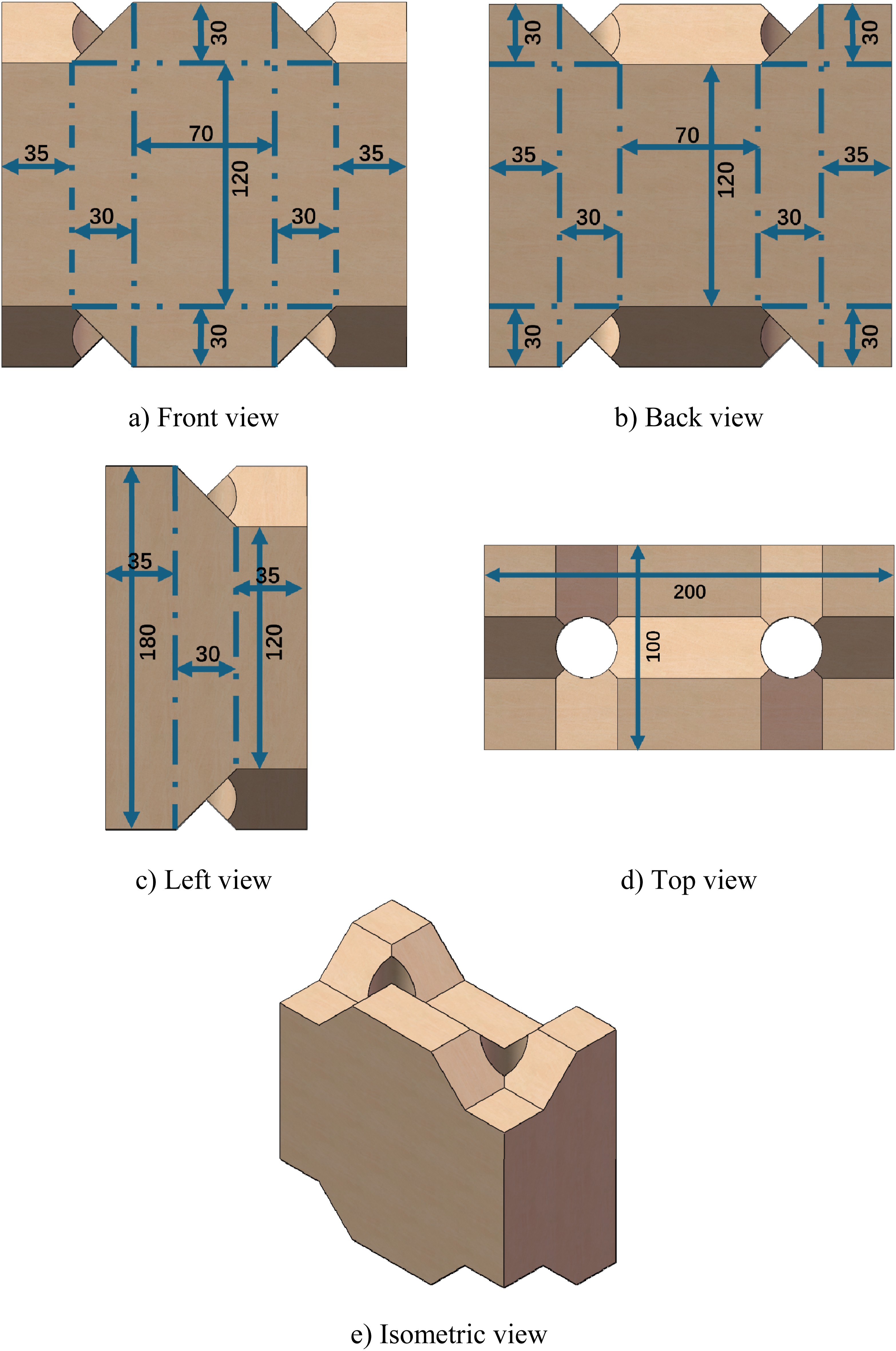
A basic cell of dry-stacking interlocking bricks as shown in Figure 2(b) is chosen as the RVE, which is comprised of two whole interlocking bricks with two pieces of half bricks as the top and bottom courses and quarter bricks distributed at four corners. Derivation of an RVE and its homogenisation. (a) Interlocking brick wall, (b) basic cell (RVE), (c) homogenised continuum.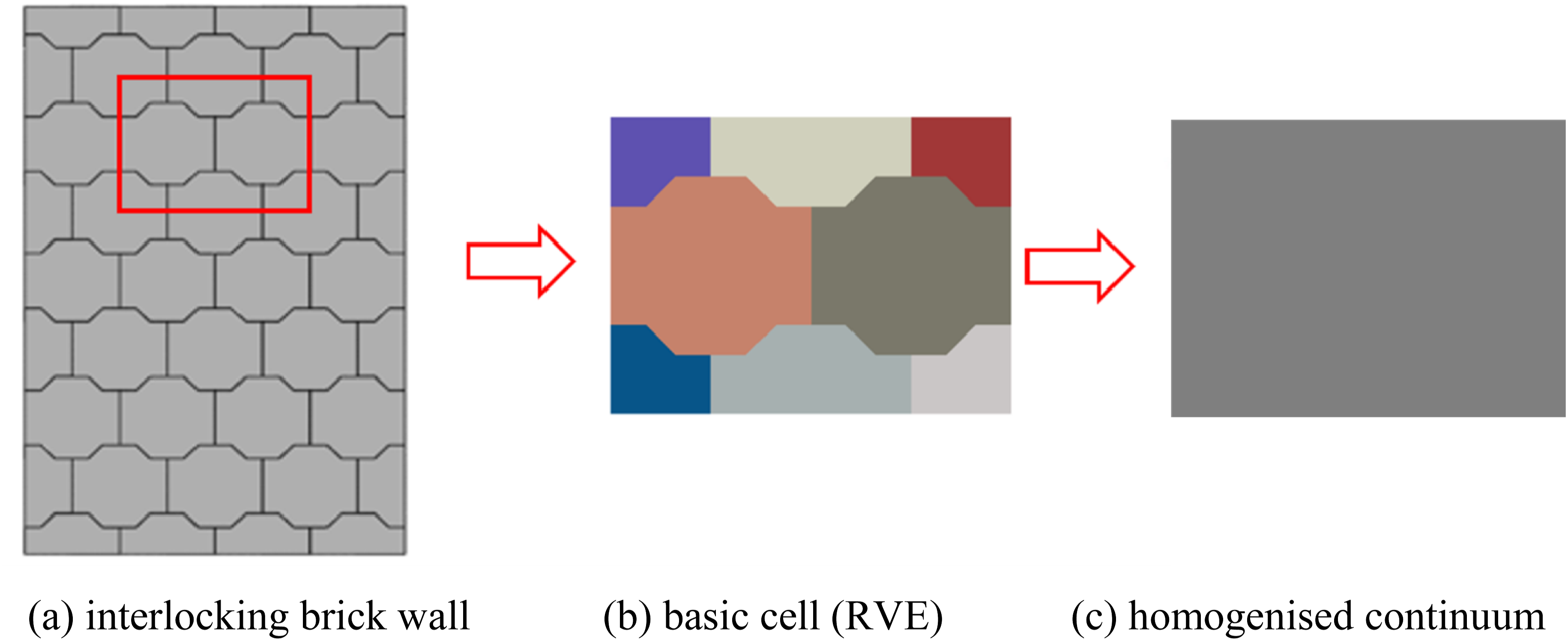
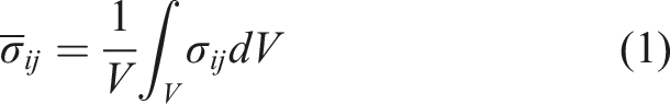
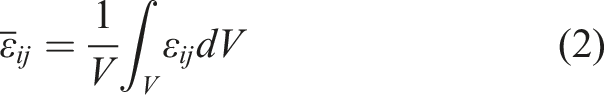
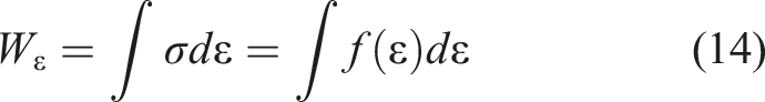
The homogenised material properties can be derived through analysing the RVE subjected to different loading conditions. To derive the constitutive stress-strain relations of the RVE in the macro-scale level, the components of the averaged stress and strain,
Numerical modelling of interlocking bricks
To obtain the homogenised RVE, a detailed numerical model of the RVE as depicted in Figure 2(b) should firstly be generated. In this study, the commercial software ABAQUS (Abaqus, 2014) is used to model the RVE and subject it to different stress states.
Material model
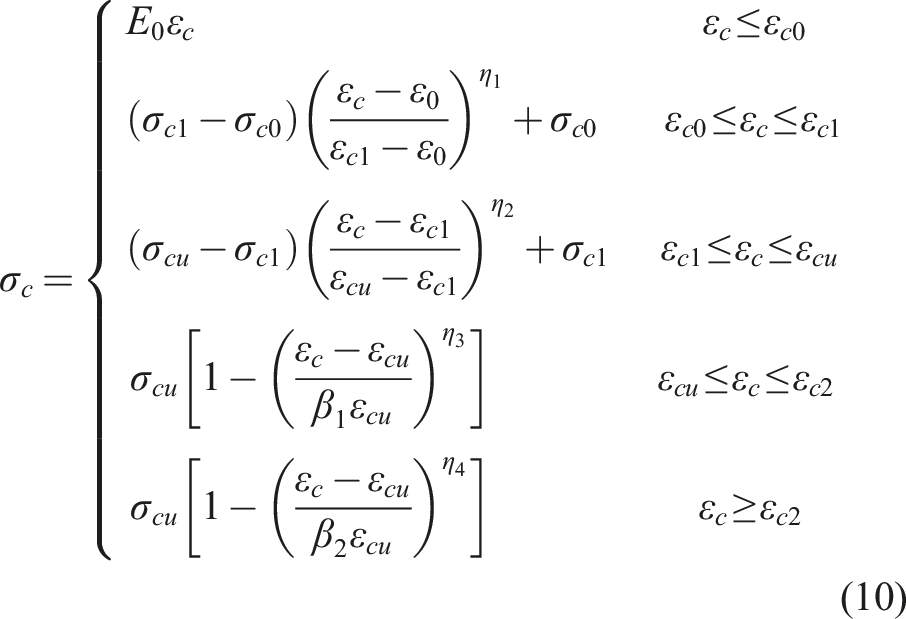
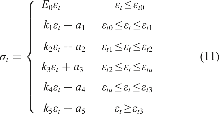
The material of each interlocking brick is modelled using the Concrete Damaged Plasticity (CDP) model in ABAQUS. The CDP model (Lubliner et al., 1989) is commonly used to simulate the nonlinear behaviour of concrete-like materials. Material hardening and softening in both compression and tension can be considered using equations (3) and (4). As illustrated in Figure 3, under uniaxial compression and tension, the stress-strain relations defining the compressive stress σc as well as the tensile stress σt are derived as follows: Uniaxial compressive and tensile behaviours of brick material in the CDP model. (a) Compression, (b) Tension.


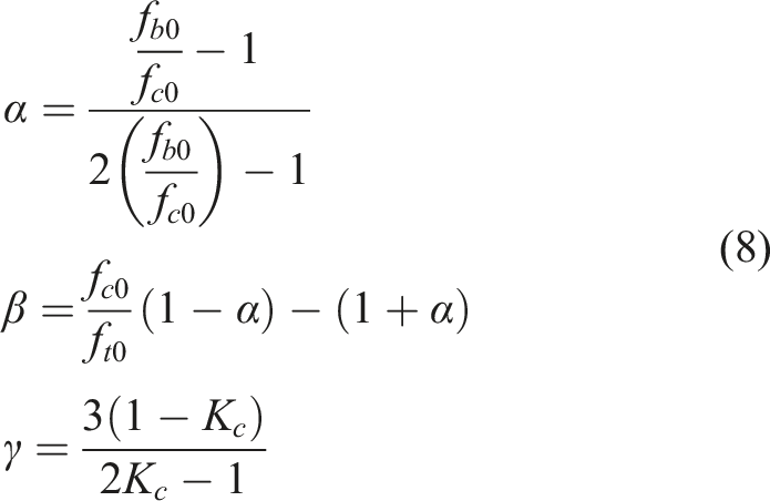
The Poisson’s ratio νc is 0.2; the Young’s modulus of brick E0 = 13.5 GPa; the unconfined uniaxial compressive strength fc is 17.8 MPa from laboratory material testing results (Shi et al., 2021b). In the study, the tension stiffening is defined according to Martínez et al.’s study (2018). The uniaxial tensile stress for the brick material is assumed as 0.1 fc (Klingner, 2017; Martínez et al., 2018; Shi et al., 2021a, 2021b). The density of brick is 2565 kg/m3. A non-associated plastic flow rule representing the plastic potential is chosen, with a dilation angle of 30°. This is to simulate the non-dilatant behaviour of brick subjected to moderate compression and shear loading (Shi et al., 2021b). fbo/fco denotes the ratio of biaxial compressive yield stress over the uniaxial compressive yield stress, which is taken as 1.16 for brick material. Smoothing of the tension corner is also used, which is reflected through taking into account the eccentricity parameter that equals to 0.1 (Milani et al., 2006; Shi et al., 2021a).
Contact properties
As the interlocking bricks are dry-stacking, the setting of the contact between the bricks plays a vital role in their numerical simulation. In this study, the contact between the dry-stacking bricks is assumed to be perfect without surface imperfection. The surface-to-surface contact algorithm in ABAQUS is adopted to model the contact between adjacent interlocking bricks. Mohr-Coulomb criterion is employed to define the tangential behaviour, where the friction coefficient is assumed to be 0.3 (Gorst et al., 2003; Martínez et al., 2018). The hard contact is adopted to define the normal behaviour at the contact. The hard contact guarantees no penetration of the contacting surfaces.
Mesh convergence study
Mesh convergence analysis is carried out, where 10 mm, 5 mm and 2.5 mm meshes are tested (Figure 4(a) shows the mesh of one interlocking unit in the RVE). Figure 4(b)–(d)) show the modelled average axial stress and strain relations of the RVE comprising of interlocking bricks with different mesh sizes that are subjected to uniaxial compression in the vertical, horizontal and out-of-plane directions, respectively. It is to note that the vertical, horizontal and out-of-plane directions correspond to the Y-, X- and Z- directions in the global coordinate systems of ABAQUS. Overall, the stress-strain curves of the three models are close to one another. As can be seen in Figure 4(b), 5 mm mesh slightly overestimates the peak compressive strength by +0.63% as compared to 2.5 mm mesh, which also slightly underestimates that with 10 mm mesh (−3.72%). Similarly, when the RVE is under uniaxial compression in the horizontal and out-of-plane directions, the RVE with 5 mm mesh only slightly overestimates the peak strengths by + 3.43% and +2.91% respectively when compared to the 2.5 mm mesh, which in the meanwhile slightly underestimates those from the model with 10 mm mesh (−1.08% and −4.70%). As CDP model which contains damage evolution is used to model brick material, simulated material damage is also checked. Figure 4(e)) shows the relation between applied displacement and the corresponding energy dissipated by material damage (ALLDMD) obtained with different element sizes at the instant of peak strength, the energy dissipated by the three models are 5847.82 mJ for the 10 mm model, 5382.76 mJ for the 5 mm model and 5221.18 mJ for the 2.5 mm model. The damage extent is slightly lower as the meshes become finer but there is only a small difference. The damage contours of the three models at peak strength are shown in Figure 4(f). It can be seen that the damage patterns are also similar, with main damage concentrated around the plane connecting the central and side parts of the interlocking bricks where abrupt changes in geometry exist. Therefore, it is demonstrated that despite the mesh dependency of CDP model, both the stress-strain results and the damage evolution do not vary much under the studied mesh sizes. The overall response of the three meshes are very similar. Therefore, it is decided to adopt the mesh of 5 mm in the interest of computational efficiency. Mesh convergence study. (a) Brick unit with different mesh sizes, (b) Stress-strain curves of the modelled RVE under vertical loading, (c) Stress-strain curves of the modelled RVE under horizontal loading, (d) Stress-strain curves of the modelled RVE under out-of-plane loading, (e) Displacement and energy dissipated by material damage (ALLDMD) curve, (f) Damage mode with different mesh sizes.
Numerical results of RVE
To derive the homogenised material properties of the RVE for interlocking bricks, responses of the basic cell is analysed under various stress states. The equivalent material properties, including the elastic properties, yield criterion, plastic flow rule, hardening and softening model, and damage model, are determined using the numerical modelling results.
Stress-strain curves under different stress states
Figure 5 shows the homogenised stress-strain relationships of RVEs under various compressive stress states. In Figure 5(a), a compressive loading in the Y direction is achieved by applying a Y-direction displacement on the top while constraint the displacement in the Y direction on the bottom. The lateral surfaces are not constrained. The uniaxial compressive strength of the RVE in this case is 7.92 MPa, which is much lower than the compressive strength of the interlocking brick material (17.8 MPa). It demonstrates that dry-stacking method could significantly influence the compressive strength of the interlocking brick structures. The compression in the X direction (or in the Z direction) is achieved in the same way as in the Y direction, with the applied displacement and constraint in the corresponding direction. The uniaxial compressive strengths of the RVE subjected to compressive loading in the X direction and the out-of-plane Z direction without confinement are 6.47 MPa and 8.04 MPa, respectively. These results indicate that the material properties of the RVE are anisotropic because of the particular design of the interlocking bricks as shown in Figure 1. Nevertheless, anisotropy in such interlocking bricks is insignificant. As shown above, the uniaxial unconfined compressive strengths vary between 6.47 MPa and 8.04 MPa with a difference less than 20%. This is mainly because of the dry-stacking approach instead of mortar for inter-brick bonding, and the negligence of the contact imperfection between the interlocking bricks. Stress-strain relations under compression-compression loadings. (a) σyy under compression in y-direction, (b) σxx under compression in x-direction, (c) σzz under compression in z-direction, (d) σxx (black) and σyy (red) under compressions in x and y directions with a displacement ratio of 4:3, (e) σxx (black) and σyy (red) under compressions in x and y directions with a displacement ratio of 1:1, (f) σxx (black) and σyy (red) under compressions in x and y directions with a displacement ratio of 3:4, (g) σxx (black), σyy (red) and σzz (blue) under triaxial compression with a displacement ratio of x:y:z = 1:0:0, (h) σxx (black), σyy (red) and σzz (blue) under triaxial compression with a displacement ratio of x:y:z = 0:1:0, (i) σxx (black), σyy (red) and σzz (blue) under triaxial compression with a displacement ratio of x:y:z = 0:1:1, j) σxx (black), σyy (red) and σzz (blue) under triaxial compression with a displacement ratio of x:y:z = 1:0:1, k) σxx (black), σyy (red) and σzz (blue) under triaxial compression with a displacement ratio of x:y:z = 1:1:1, l) X, Y and Z directions in above studies.
When the RVE is under biaxial compression, the vertical normal displacement on the top surface and the lateral normal displacement on the left surface is monotonically increased. The normal displacements on the opposite surfaces are constrained. When subjected to biaxial compression, the stress-strain relations of the RVE are shown in Figure 5(d)–(f)). To examine the different stress states, various ratios of displacements and thus strains in each direction are applied. Typically for x:y = 1:1 as shown in Figure 5(e), the compressive strengths of the RVE in the X direction and the Y direction are 9.32 MPa and 13.26 MPa, respectively, which are both higher than the corresponding unconfined uniaxial compressive strengths. The corresponding strains at the peak stresses are both similar to those subjected to unconfined uniaxial loading. It indicates that when the RVE is subjected to biaxial loading, its compressive strength increases because of the confinement. When the applied displacement in the X direction increases (x:y = 4:3), the compressive strength in the X direction slightly improves, while the strength in the Y direction gradually decreases. This is because the nonuniform loadings in the two directions induce deviatoric stress in the RVE, besides the compressive stress. The combined compressive and shear stress lead to the reduction of the compressive strength in the Y direction. However, the compressive strength in the X direction slightly increases. According to the biaxial tensile-compressive failure criteria for ordinary concrete developed by Kupfer et al. (1969), as one principal stress decreases, the other would increase.
Figure 5(g)–(k) show the stress-strain curves of the RVE when subjected to triaxial compression. As shown in Figure 5(g), when the RVE is restrained in both the vertical Y and the out-of-plane Z directions, the peak compressive capacity is more than 50 MPa in the horizontal direction (X direction), which is significantly higher than that without constraints. Similar observations can be found in Figure 5(h), when the RVE is constrained in the other two directions. With constraint in the X direction and loading in the Y and Z directions (Figure 5(i)), the compressive strengths of the RVE are substantially higher than those in Figure 5(a)–(c). When the REV is subjected to triaxial loading (as shown in Figure 5(k)), the compressive strengths increase insignificantly comparing to the cases with one axis constrained as in Figure 5(i). It is to note that a ‘plastic plateau’ is developed on the Z direction when the RVE is constrained in the X direction. This is because of the damage of the interlocking brick (see Figure 5(i)). The fracture of interlocking bricks leads to considerable deformation of the RVE forming the plateau. Then, stress within the RVE redistributes resulting in the compaction of the RVE, which could withstand a higher load. Similar observation was reported in a previous study on the triaxial behaviour of concrete (Wang and Song, 2015). Overall, from the above observations, significant compressive strength enhancement is found on the RVE for dry-stacking interlocking brick wall under biaxial and triaxial loading.
For the RVE under tension in the X direction, the top and bottom surfaces of the RVE are left free to move, while a non-zero displacement boundary condition in the X direction is applied at one of the lateral surfaces perpendicular to the X-axis when the opposite surface is constrained with a fixed boundary condition. Similar boundary conditions are applied in the Z direction for the RVE under tension in the Z direction. Figure 6(a)–(b)) show the stress-strain curves of the RVE when it is subjected to unconfined uniaxial tension in the X and Z directions, where the corresponding tensile strengths are 0.197 MPa and 0.903 MPa, respectively. It is to note that the tensile strength of the RVE in the Y direction without any confinement is 0. This is because for dry-stacking interlocking bricks without mortar bonding, the tensile strength in the stacking direction (i.e., the vertical direction) is negligible. For the RVE under biaxial tensile loading, two tensile displacements normal to the left and the front surfaces of the specimen are applied and the corresponding movement in the direction on the opposite surfaces are fixed while the other surfaces are free. When the RVE is subjected to biaxial tensile loading in the horizontal X and the out-of-plane Z directions (Figure 6(c)), the maximum tensile strength in the horizontal X direction decreases substantially to below 0.1 MPa, but that in the Z direction shows negligible difference comparing to that under uniaxial tension. As shown in Figure 6(d), when confinement is applied to the Y direction, the maximum tensile strength in the X direction reduces marginally. It indicates that the constraint in the vertical direction has negligible influence on the biaxial tensile behaviour of the RVE. When the RVE is subjected to the tensile-compressive loadings (see Figure 6(e)), the tensile strength also has no obvious change as compared to that under the uniaxial tension loading condition, where the failure of the RVE is resulted due to the maximum tensile strain is reached before the maximum compressive strength is met. Similar observation can be found when the RVE is subjected to the combined tensile-compression-compression loading as shown in Figure 6(f). Stress-strain relations under compression-tension and tension-tension loadings. (a) σxx under tension in x-direction, (b) σzz under tension in z-direction, (c) σzz under tension in x and z directions with a displacement ratio of 1:1, (d) σxx (black), σyy (blue) and σzz (red) under triaxial tension with a displacement ratio of x:y:z = 1:0:1, (e) σyy (blue) and σzz (red) under compression in y direction and tension in z direction with a displacement ratio of −1:1, (f) σxx (black), σyy (blue) and σzz (red) under compression in x and y directions and tension in z direction with a displacement ratio of x:y:z = −1:-1:1.
Figure 7 illustrates the stress-strain curves of the RVE when subjected to pure shear, in-plane compression-shear, and out-of-plane compression-shear loadings. For the RVE under pure shear loading, a monotonically increasing tangential displacement is applied on the top surface without any normal force, while the bottom surface of RVE is restrained for simplicity. The shear strengths of τyx, τzy and τxz are 0.08 MPa, 0.209 MPa and 0.057 MPa, respectively, when subjected to pure shear loading (Figure 7(a)–(c)). It is observed that the shear strength τzy is significantly higher than τyx and τxz, because of the existence of shear keys in the interlocking bricks. Inter-brick sliding occurs when the RVE is subjected to pure shear in the YX and XZ planes. For the RVE under compression-shear loading, a monotonically increasing shear displacement is applied followed by a corresponding monotonically increasing normal (compressive) displacement on the same surface. Figure 7(d) shows the stress-strain curves when the RVE is under the in-plane compression-shear loading. As can be seen, the shear strength significantly increases compared to that under the pure shear loading condition. Moreover, when the RVE is subjected to out-of-plane compression-shear loading, the shear strength also increases significantly (see Figure 7(e)). This demonstrates that for dry-stacking interlocking bricks, compressive stress is critical for the effective action of shear key in improving the shear resistance performance. Stress-strain relations of RVE under compression-shear loadings. (a) τyx-εyx under shear loading in x direction, (b) τzy-εzy under shear loading in y direction, (c) τxz-εxz under shear loading in z direction, (d) τyx and σyy under compression in y direction and shear in x direction, (e) τzy and σzz under compression in z direction and shear in y direction.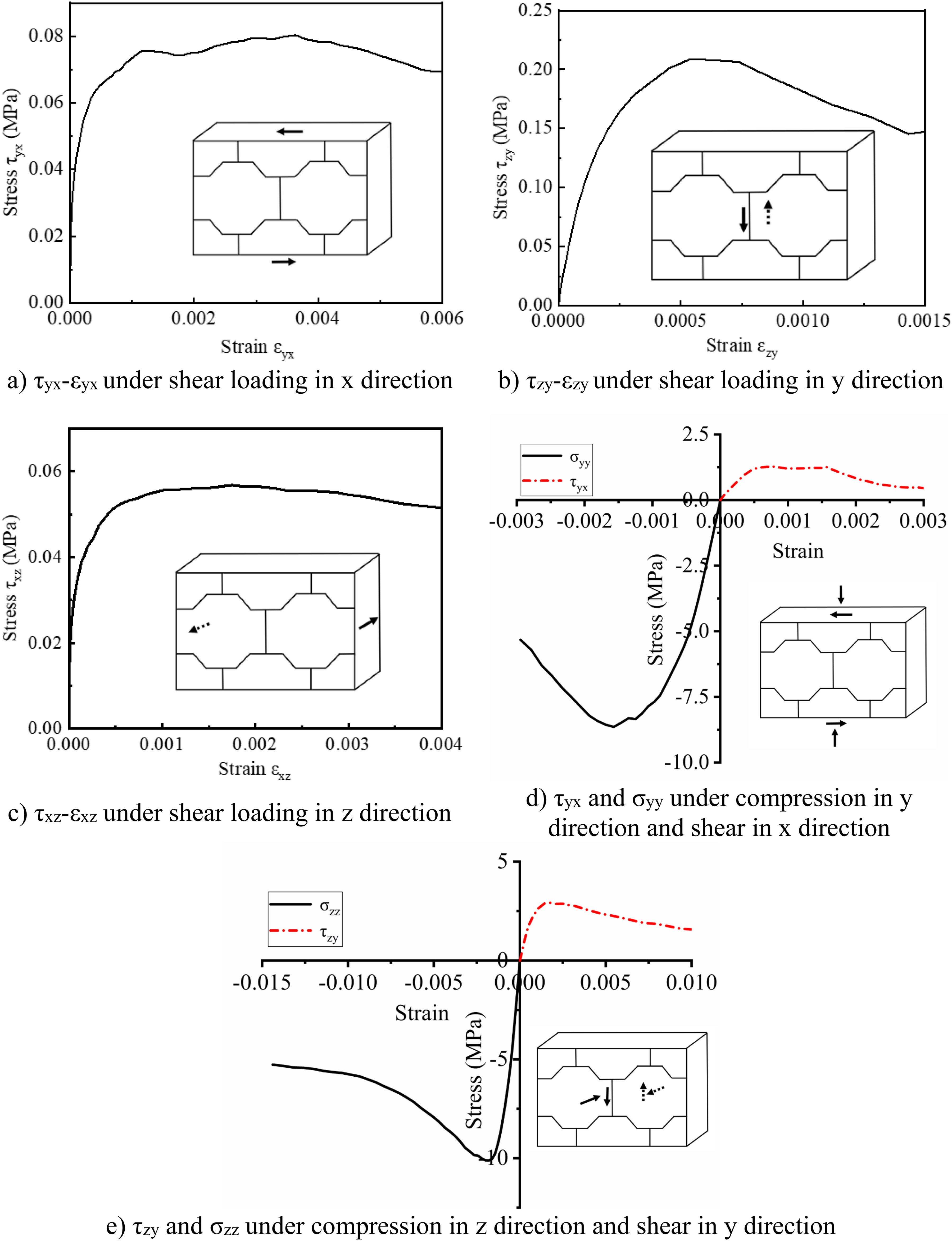
Equivalent material properties of RVE
In this section, the above numerical results of the RVE under different stress states are used to derive the equivalent material properties and the constitutive model of the RVE for interlocking brick walls, including the elastic properties, yield criterion, the plastic flow rule, hardening and softening rule, and damage model.
Elastic properties
As the basic material properties, the equivalent elastic modulus and Poisson’s ratio can be derived from the stress-strain curves (Figure 5(a)–(c)) when the RVE is subjected to uniaxial compressive loadings. The shear modulus can be obtained from the stress-strain relations, as shown in Figure 7(a)–(c) when the RVE is under pure shear loadings. From the above results, the elastic moduli of the equivalent RVE material are obtained as Ex = 9.13 GPa, Ey = 9.32 GPa, Ez = 9.13 GPa, Gyx = 1.02 GPa, Gzy = 1.06 GPa, Gxz = 1.07 GPa, and the Poisson’s ratio can be calculated as νyx = 0.23, νzx = 0.21, and νzy = 0.22. Since the elastic modulus, Poisson’s ratio, and the strength are very similar in the three directions, an isotropic material model is employed herein to simplify the modelling, where the equivalent material of RVE for interlocking bricks is assumed having the same elastic modulus and Poisson’s ratio in the three directions. This isotropic material model is to be validated in a later section of this paper to examine its accuracy and suitability. The averaged value of elastic modulus in the three directions, that is,
Yield criterion
The yield criterion of the equivalent material of the RVE for the interlocking bricks is important to simulate the homogenised continuum model. Based on the numerical results of the stress-strain relations for the RVE under different stress states (Figures 5-7), the equivalent failure envelope can be derived based on the maximum strength of the RVE.
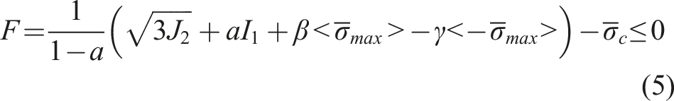
In this material model, the yield function is assumed as follows:

Other parameters are defined as follows: Biaxial failure envelope in plane stress space.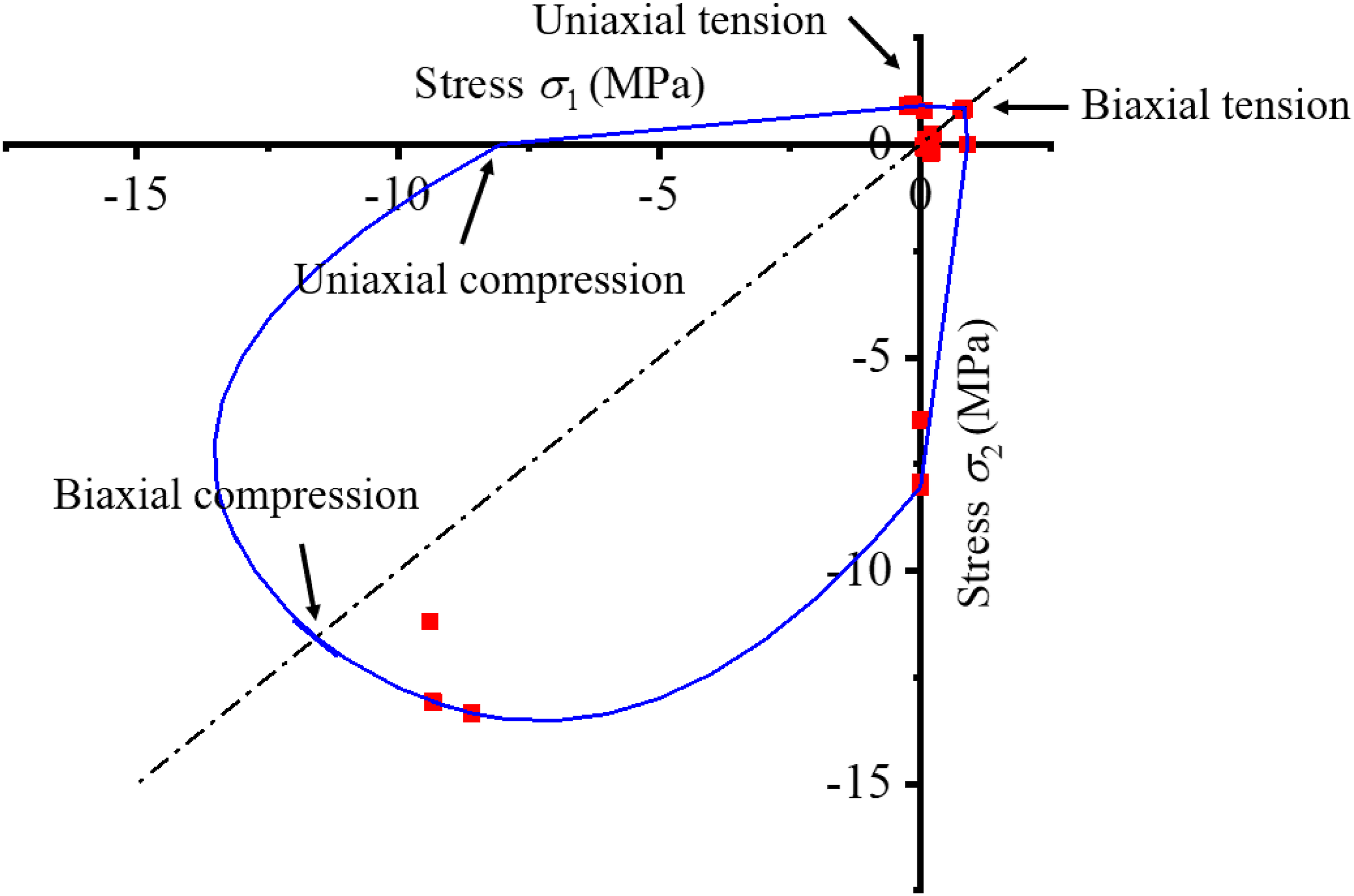
According to the hydrostatic pressure Failure surface in the deviatoric and meridian planes. (a) Deviatoric plane, (b) Meridian plane.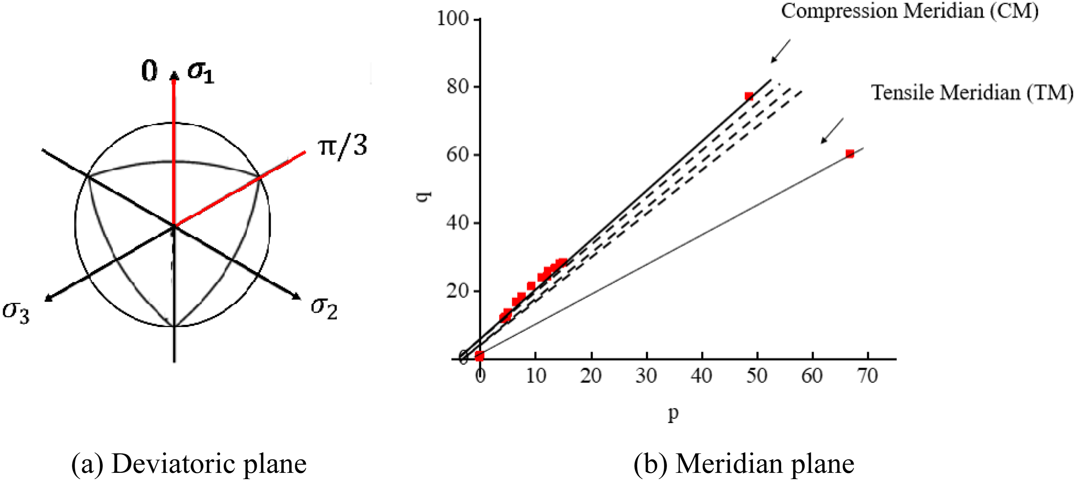
Plastic flow rule
The plastic flow rule is also a vital part in the nonlinear behaviour of the equivalent material model for the RVE of the interlocking brick assembly. Since an associated flow rule for the yield surface gives an unrealistically high volumetric expansion in compression, which leads to an overestimated peak stress (Chen and Han, 2007), the shape of the homogenised continuum loading surface at any given point is obtained by using the non-associated plastic flow rule (Voyiadjis and Taqieddin, 2009). The potential function G in equation (9) has a hyperbolic Drucker-Prager form.

The non-associated plastic potential dilation angle (a) The plastic potential in the meridian plane; and (b) confined uniaxial stress-strain relations under different pressures in the Y-direction.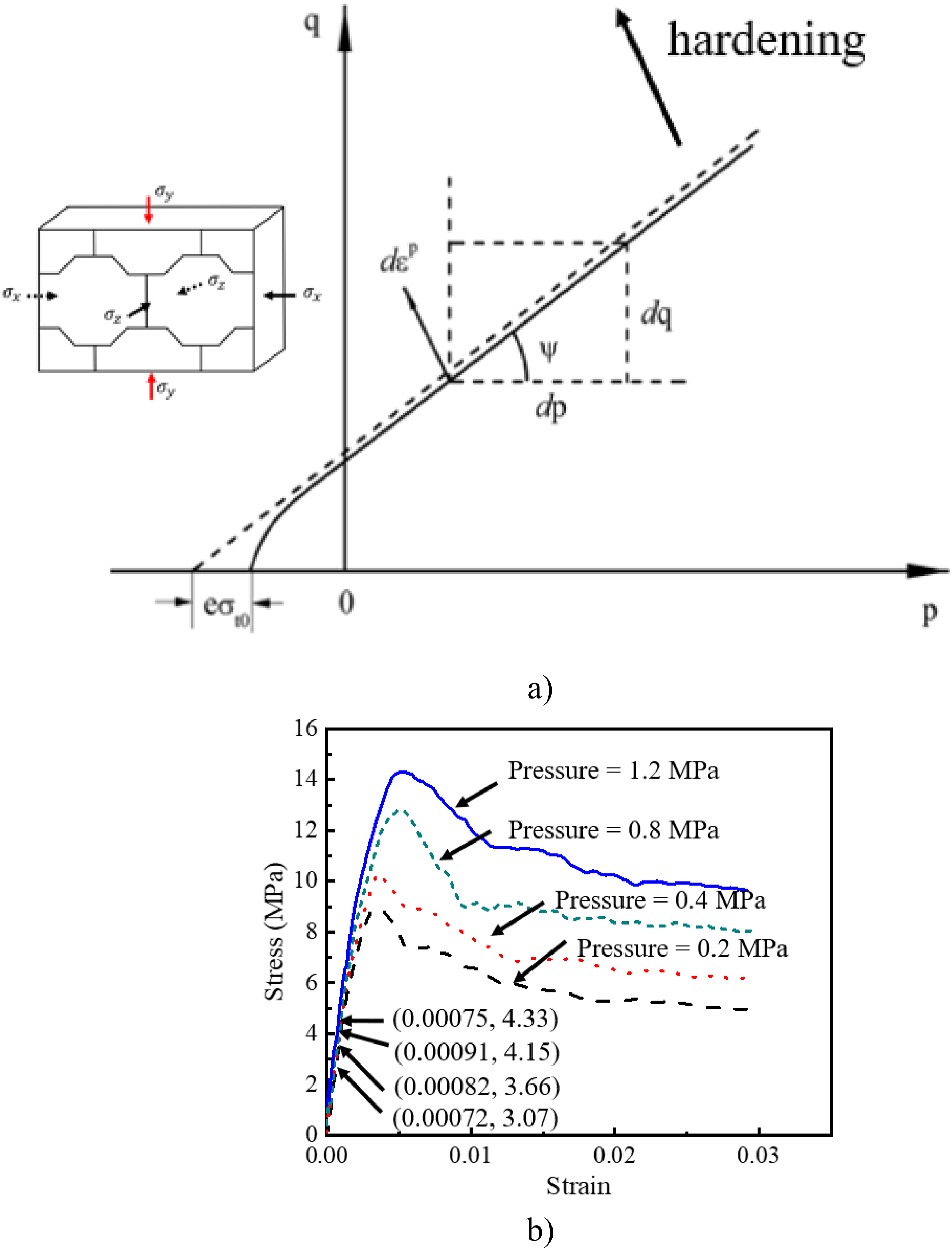
Hardening and softening
To depict the constitutive behaviour more accurately, the hardening and softening effects are considered in the derivation of the equivalent material properties of the RVE. Without losing generality, Figure 11 shows the stress-strain curves of the RVE under uniaxial stress states, which comprises of an elastic stage, a hardening stage, and a softening stage. A multilinear consecutive model is used in the homogenised continuum to depict the elastic, hardening and softening behaviours as defined in equations (10) and (11). Stress-strain relations of the RVE under uniaxial stress states (a) compression; (b) tension.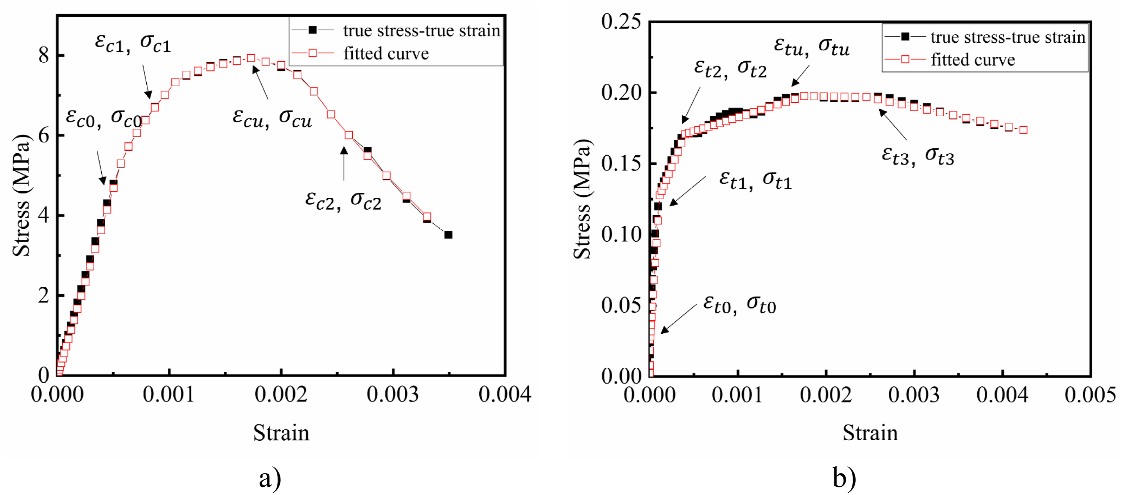
Damage model
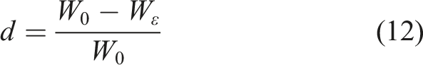
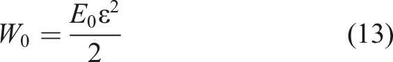
Being a vital part in nonlinear material models, the damage variables in this study are based on the continuum damage mechanics theory (Voyiadjis and Kattan, 2009, 2015; Walton et al., 2014). The damage scalar d that varies between 0 and 1 can be written as:
and Material damage based on the continuum damage mechanics theory (Voyiadjis and Kattan, 2009, 2015; Walton et al., 2014).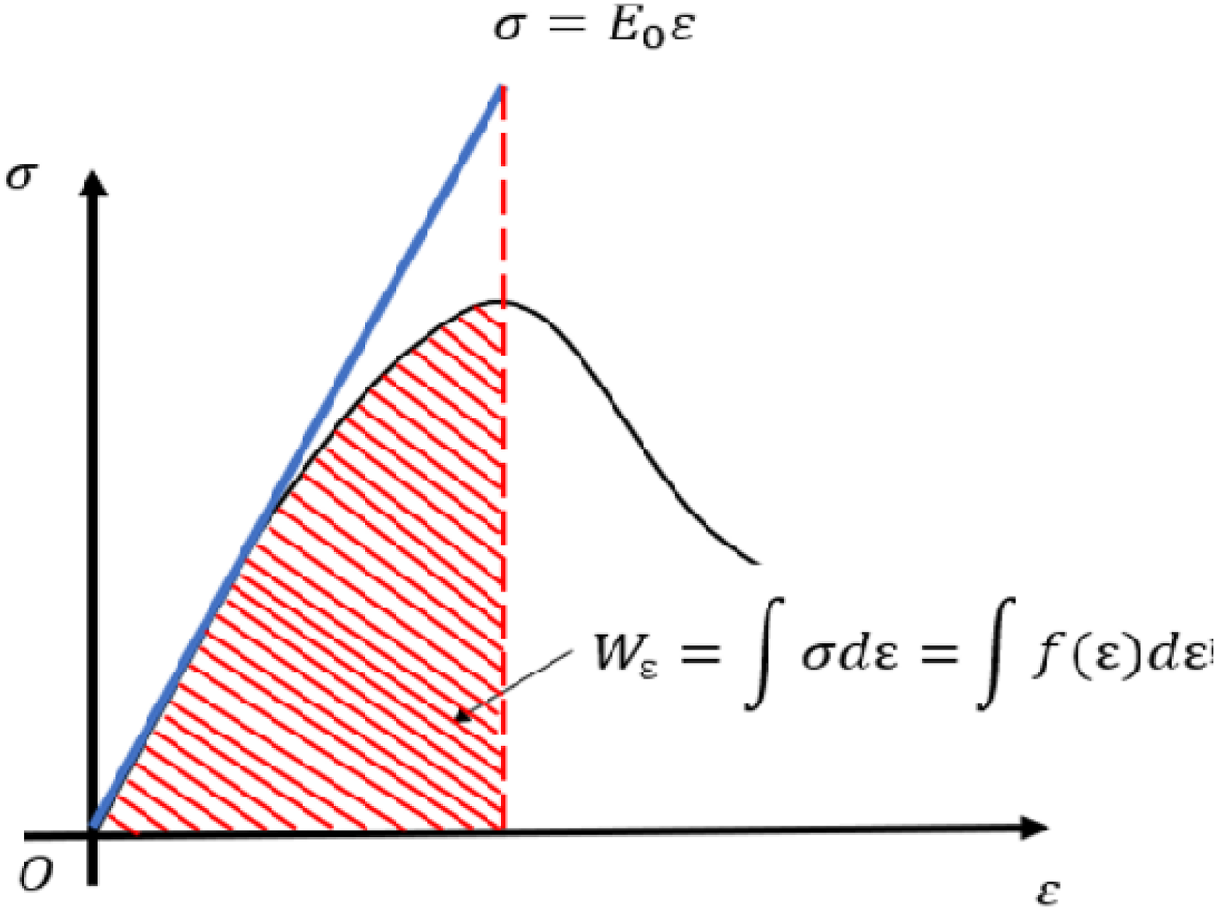
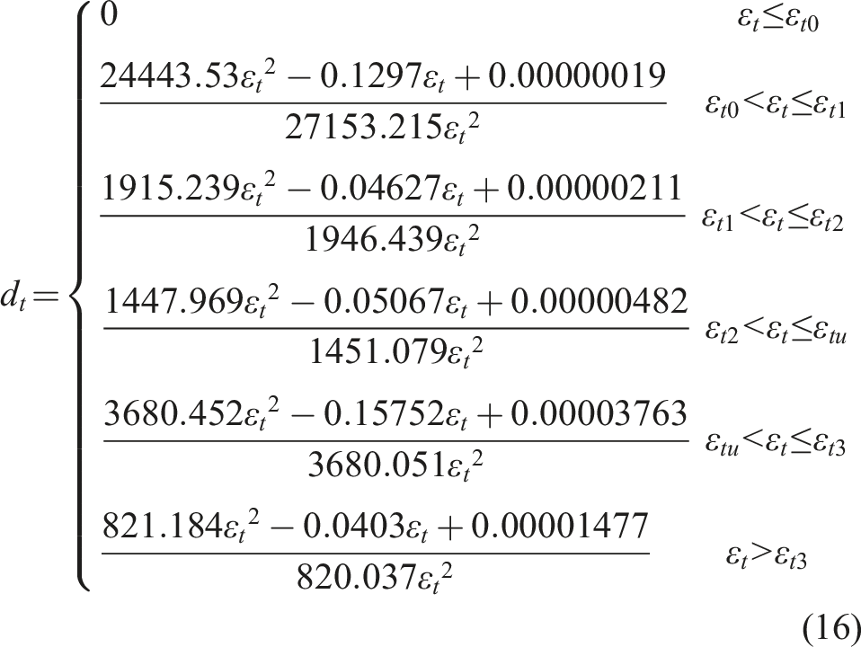
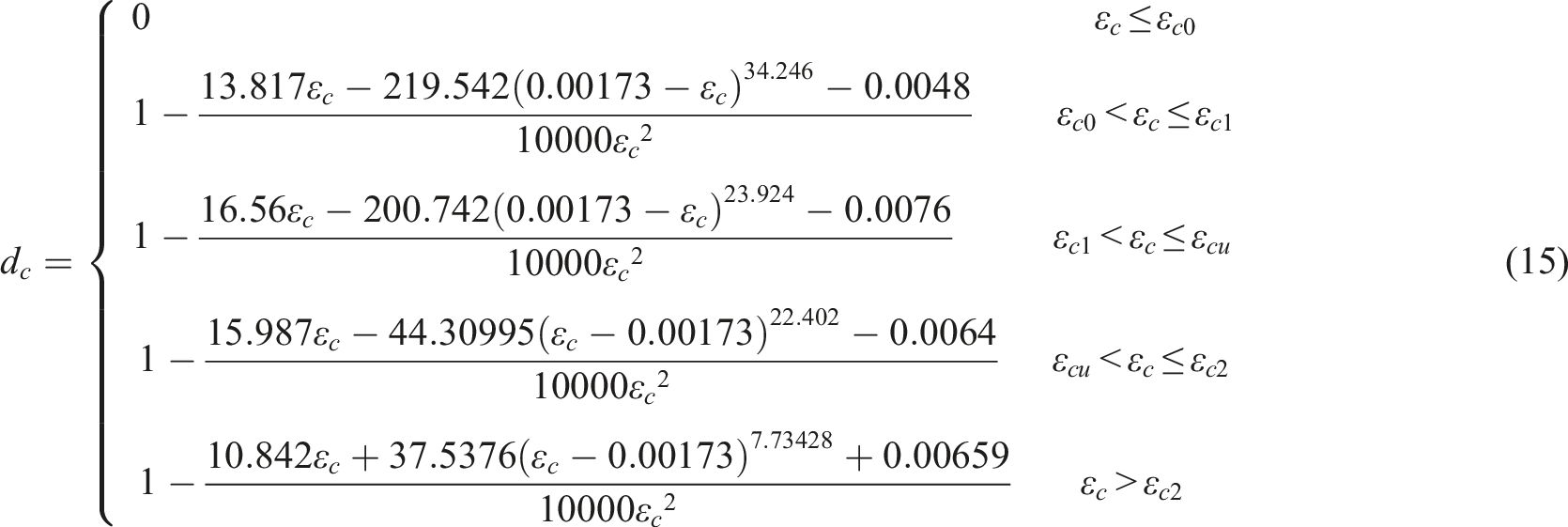
Substituting these variables and equation (13) into equation (12), the compressive damage scalar dc and the tensile damage scalar dt can be obtained as equations (15) and (16). No damage exists in the elastic region but only in the inelastic region. The damage parameter under compression corresponding to the maximum compressive stress
Size effect and model validation
Size effect
As discussed in Methodology, the selected RVE should be as small as possible to ensure the stress in the element being uniform. On the other hand, the RVE should also be large enough to include all features of interlocking bricks. Despite the RVE selected could satisfy the basic requirements, to ensure the applicability and the reliability of the derived homogenised material properties, size effect of the RVE is examined. As shown in Figure 13(a)), the selected RVE has a width of 400 mm, a height of 300 mm, and a thickness of 100 mm. A 2 × 2 RVE as shown in Figure 13(b) is numerically modelled under different stress states to evaluate the size effect. Models for examining the size effect. (a) 1 × 1 unit, (b) 2 × 2 unit.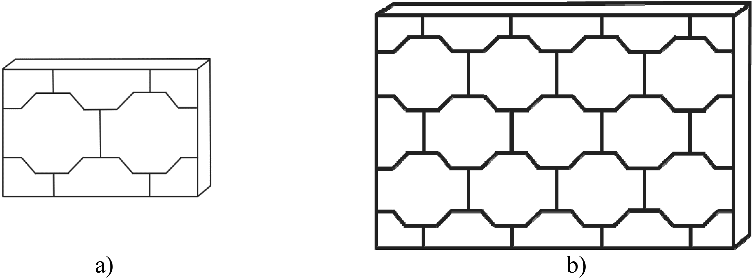
Figure 14 compares the stress-strain curves of the 1 × 1 unit and the 2 × 2 unit. When they are subjected to uniaxial compression in the X direction (see Figure 14(a)), the compressive strength of the 1 × 1 unit is 6.47 MPa, while that of the 2 × 2 unit is 6.52 MPa reflecting less than 1% difference. The initial stiffnesses of the two models also align well indicating the elastic modulus is independent of the size of the RVE when the equivalent material properties are applied to the homogenised continuum. When they are subjected to uniaxial compression in the Y direction as shown in Figure 14(b), the compressive strength of the 1 × 1 unit is 7.92 MPa, while that of the 2 × 2 unit is 8.13 MPa with a discrepancy of 2.65%. When subjected to uniaxial tensile loading in the out-of-plane Z direction, the maximum strength of the 1 × 1 unit is 0.903 MPa, while that of the 2 × 2 unit is 0.901 MPa (as shown in Figure 14(c). Figure 14(d) shows the modelled stress-strain curves of the 1 × 1 unit and 2 × 2 unit subjected to compression-shear loading. The maximum shear stress of the 2 × 2 unit is slightly larger than that of the 1 × 1 unit with a difference less than 6%. Overall, the above evaluations show small difference in the stress-strain relations between the 1 × 1 and the 2 × 2 units, demonstrating the negligible size effect on the selected RVE. Size effect of the RVE. (a) Uniaxial compression in the X direction, (b) Uniaxial compression in the Y direction, (c) Uniaxial tension in the Z direction, (d) Compression-shear in the Y direction.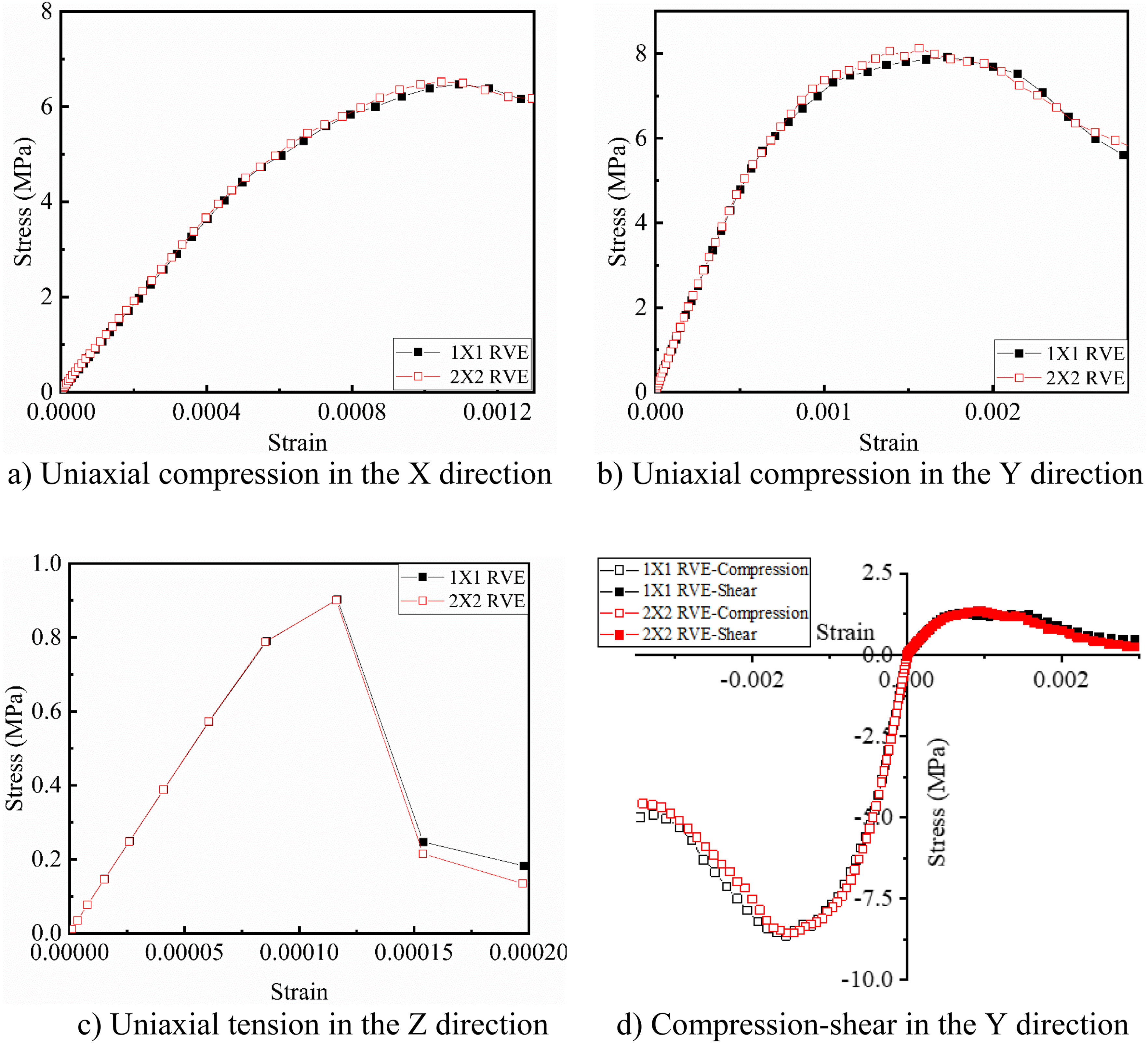
Model validation
To validate the suitability and accuracy of the RVE with the derived equivalent material model, the homogenised material properties are used to model the uniaxial compressive behaviour and the compression-shear behaviour of an interlocking brick wall. The interlocking brick wall is 1200 mm width, 900 mm height, and 100 mm thickness, which is fixed on the ground. It is firstly subjected to a uniaxial compressive load through displacement-controlled loading method. Then, in compression-shear case, another wall of the same size is subjected to the prescribed compressive loading and then horizontal shear loading through displacement control method. Mesh dependence study is firstly conducted to examine the influence of mesh size for the RVE. Then, the numerical modelling results are compared with data from detailed numerical modelling.
Mesh dependence
In the mesh dependence study, four different mesh sizes, i.e., 7.5 mm, 15 mm, 30 mm, and 60 mm, are considered. Figure 15(a)) compares the stress-strain curves modelled using the RVE under compressive loading with different mesh sizes, where negligible difference can be seen. When the RVE wall is subjected to compression-shear loading as shown in Figure 15(b)), small variations can be found on the modelled stress-strain curves. In the meanwhile, Figure 15(c) and (d) compares the computational times using the four different mesh sizes. The numerical modelling results are obtained from a PC with Intel Core i7-7700 CPU 3.60 GHz with 16 GB RAM. As expected, the computational time reduces exponentially as the adopted mesh size increases. The above study demonstrates that when employing RVE method for interlocking brick wall, a relatively coarse mesh size could still give reasonably accurate predictions while significantly reduces the computational time. In this study, 30 mm mesh size is chosen for the subsequent numerical modelling. Result comparison of mesh dependence study. (a) Stress-strain curves under compression, (b) Stress-strain curves under compression-shear, (c) Computational time for compression, (d) Computational time for compression-shear.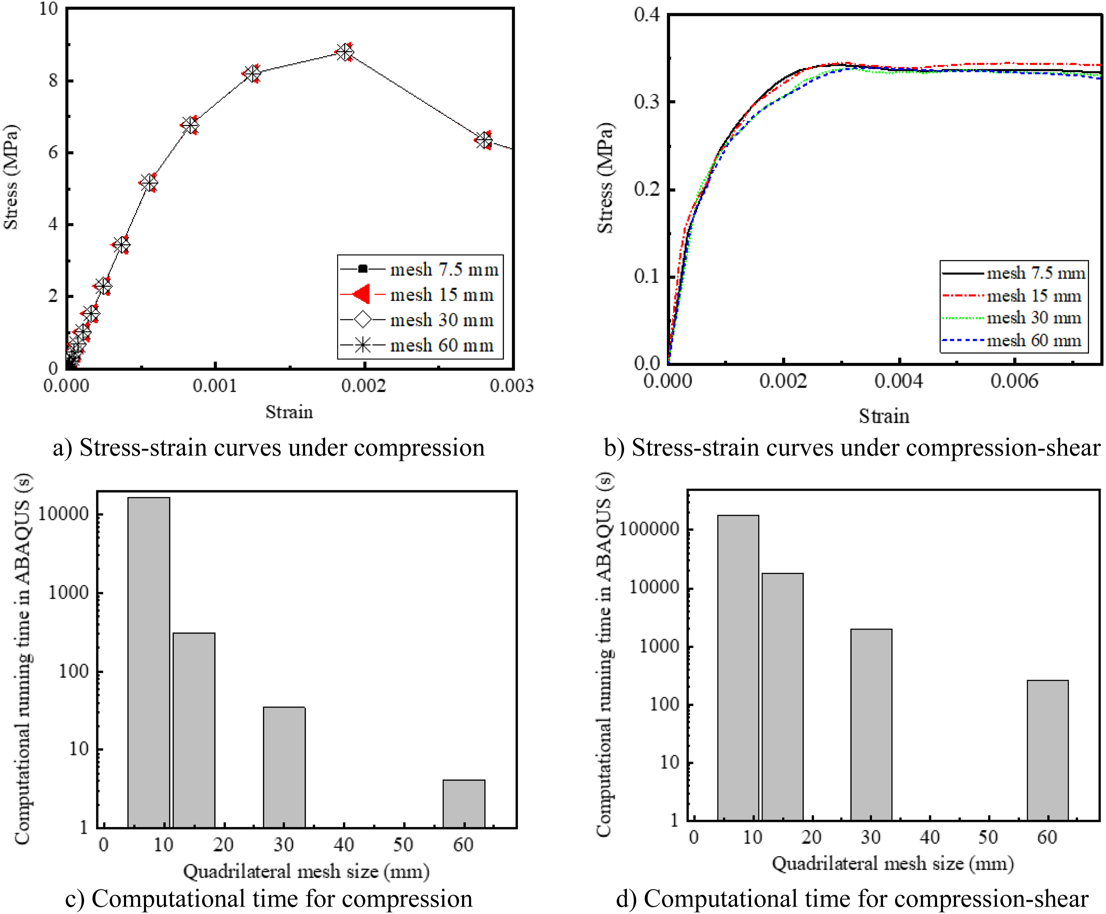
Uniaxial compression
To validate the derived homogenised model under uniaxial compression, comparison is made between the homogenisation method employing the RVE with the equivalent material properties as described above with 30 mm × 30 mm mesh and a detailed FE method employing three-dimensional continuum elements with eight-node reduced integration (C3D8R) using 15 mm × 15 mm mesh. Figure 16 shows the compressive stress-strain relations from these two models subjected to uniaxial compression in the X, Y and Z directions. It can be found that the modelling results of the homogenisation method is very close to those from the detailed model. For example, the maximum compressive strengths in X and Y directions are 8.46 MPa and 8.80 MPa, with 7.63% and 5.77% error compared to the detailed modelling (7.86 MPa and 8.32 MPa). The initial moduli of the two models are also very close indicating the stiffness of the homogenisation method could accurately represent that of the detailed modelling. When the interlocking brick wall is subjected to compressive loading in the Z direction, an ultimate strength of 10.71 MPa is predicted by the homogenisation model. Compared to 10.73 MPa from the detailed model, the difference is 0.19%. In terms of the computational efficiency, when using a computer as described in last paragraph to model the interlocking brick wall under uniaxial compression in the Y direction, the homogenised continuum model requires 155 MB memory in comparison to the 1659 MB memory requirement for the detailed model. And the calculation time decreases from 100,044 s to only 34.6 s, reflecting an 90.66% memory reduction and 99.97% computation time saving. It is apparent that the homogenised modelling method could substantially save the computational resource while giving reliable prediction of interlocking brick walls under vertical compressive loading. Comparison of stress-strain curves of the homogenisation method and the detailed modelling method for the interlocking brick wall under uniaxial compression. (a) Uniaxial compression in the X direction, (b) Uniaxial compression in the Y direction, (c) Uniaxial compression in the Z-direction.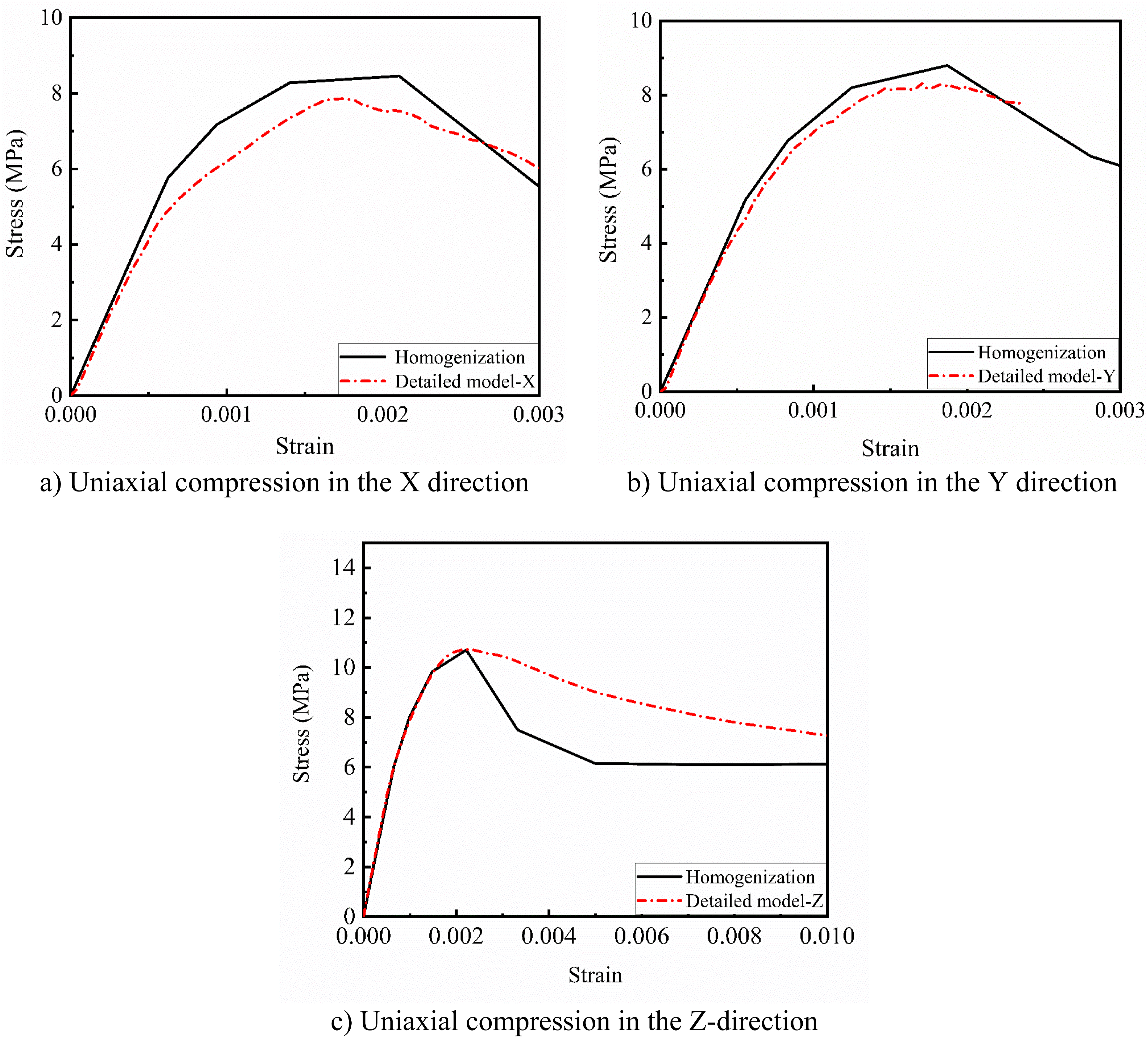
Compression-shear
To further validate the homogenisation method for interlocking brick wall, the interlocking brick wall subjected to compression-shear loading is modelled. The results are compared with those using detailed models. The same wall as described above is modelled with detailed and homogenised modelling for comparison. A high-strength steel plate (1400 mm × 200 mm × 50 mm) is applied to distribute the shear load from the loading point to the surface of the wall. Nodes of the contacting steel plate and the bricks are shared and merged together. The material properties of the high-strength steel follows previous study (Shi et al., 2021b). A uniform pressure of 0.3 MPa is applied to the interlocking brick wall in the Y direction. As above, in the homogenisation method, the RVE with the equivalent material properties is employed with 30 mm × 30 mm mesh size. Solid elements (C3D8R) with 15 mm mesh are adopted in the detailed model. Gradually increased in-plane horizontal load controlled by displacement in the X direction is applied to the left-up corner of the wall, while the footing is fully fixed. Figure 17 shows the simulated engineering shear stress vs engineering shear strain curves from the two models. It can be seen that although the homogenisation model slightly underestimates the initial modulus, it could reasonably replicate the behaviour of the interlocking brick wall as that of the detailed model. An ultimate shear strength of 0.338 MPa is predicted by the homogenisation model, while that by the detailed model is 0.352 MPa. The difference between the predicted shear strength from the two models is 3.98%. Comparison of engineering shear stress-engineering shear strain curves of the homogenisation method and the detailed modelling method for the interlocking brick wall under compression-shear loading.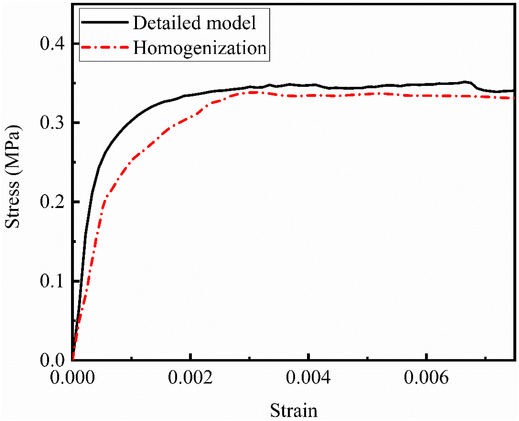
Figure 18 compares the failure patterns of the detailed model and the homogenisation model, where material damage is depicted by the equivalent plastic strain. At the instance when the peak shear strength is reached, damage mainly concentrates at the bottom right corner of the detailed model. In comparison, in the homogenised model, similar damage pattern is predicted but with more severe damage. Overall, the homogenised model consumes 210 MB of memory and takes 2029.7 s to complete the numerical analysis, while the detailed model demands 2148 MB memory and requires 109,218 s for the same analysis. It reflects a 90.22% memory saving and a 98.14% computation time saving, which proves the efficiency of the homogenisation approach. Through the above comparisons, it can be found that the homogenised modelling method could very effectively and efficiently predict the responses of dry-stacking interlocking brick wall, significantly ease the complexity of the design analysis of such masonry structures. Since the developed approach is derived using complex stress states, which considers elastic properties, strength model, plastic flow rule, hardening and softening, and damage model, it can thus be applied to model the interlocking brick walls under complex loading conditions and stress states. Comparison of damage contours of the homogenisation method and the detailed modelling method for the interlocking brick wall under compression-shear loading. (a) the detailed model, (b) the homogenised model.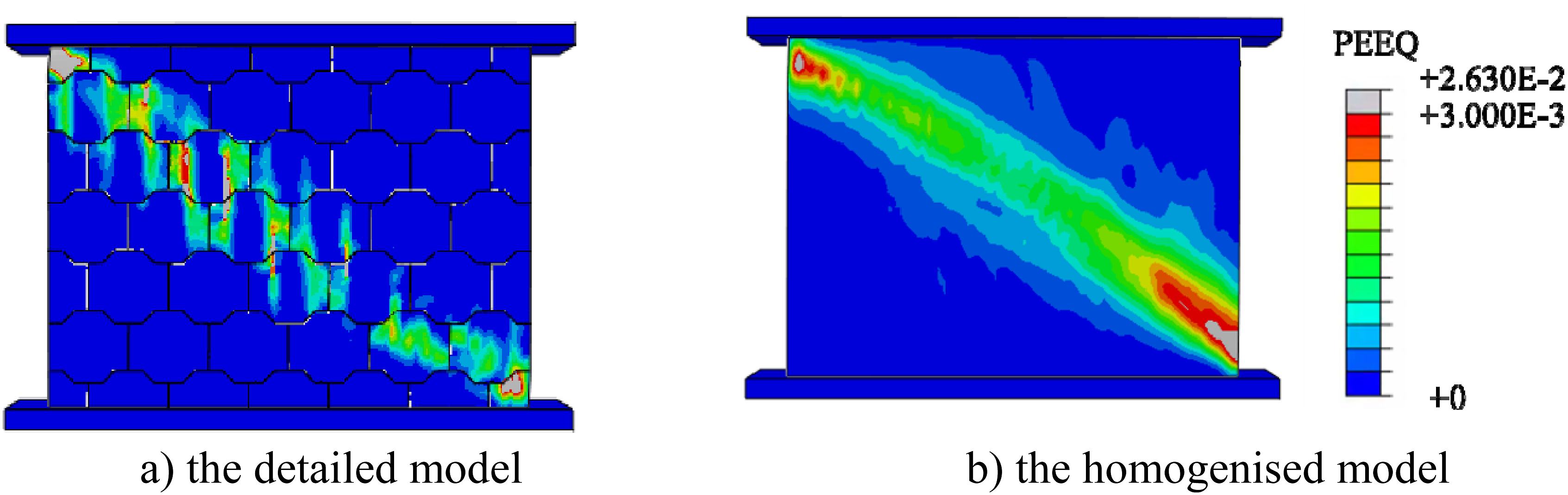
Conclusions
In this study, a homogenisation modelling method for dry-stacking interlocking brick wall is developed. The different stress states of the selected RVE are numerically modelled for determination of the equivalent material properties. The equivalent elastic properties, yield criterion, non-associative plastic flow rule, hardening and softening effects, and damage model of the RVE are determined. Size effect of the selected RVE is also examined. The accuracy and suitability of the developed homogenisation method for dry-stacking interlocking brick wall are assessed through comparing the modelling results from homogenised and detailed numerical model. The following conclusions are drawn from this study: (1) Numerical results from the RVE under different stress states show insignificant anisotropic material properties of dry-stacking interlocking brick wall; therefore, isotropic constitutive model is developed. (2) Through modelling the RVE under different stress states, the equivalent constitutive model parameters of interlocking brick wall are derived. (3) On the selected RVE for interlocking brick wall, insignificant size effect is demonstrated. Therefore, the RVE can be applied to model the response of interlocking brick structures. (4) Model validation is performed through comparing the results from the homogenised model and detailed model of an interlocking brick wall under uniaxial compressive loadings in three directions and combined compression-shear loading. Reliable predictions of interlocking brick wall responses are obtained at less than 10% computer memory and 5% computational time as compared to the detailed modelling. The developed RVE model can be used to efficiently predict the responses of interlocking brick walls under static loading.
There are some limitations for this study. For example, as stated above, due to the insignificant anisotropy of the RVE, an isotropic homogenised constitutive model is adopted. However, in practical applications, especially when it comes to large-scale structures, the influences of such approximation are to be determined by future studies, especially real-world tests which considers a variety of factors, including different load types, geometric and material imperfections, and brick surface conditions.
Likewise, in the size effect study in Size effect, a 2 × 2 RVE unit is chosen rather than a large one because the thickness of the RVE panel remains the same with its expansion in the length and height directions (always being equal to the thickness of a single brick). If a larger RVE unit is chosen, the slenderness ratio of the panel will be large, giving rise to a tendency of geometric instability. It thus leads to a structural performance instead of material performance. In future studies, RVE units with more wythes of bricks can be incorporated, by which RVE units with a scale larger than 2 × 2 can be used in the study of size effect.
It should be noted that as mentioned above, the study is conducted around the dry-stacking interlocking masonry composed of a specific type of interlocking bricks — Tetraloc bricks. Therefore, the results of this study can only be applied to dry-stacking interlocking masonry structures made of this type of bricks when no modification is made. Nonetheless, the methodology provided in this study, including how the elastic properties are extracted from the RVE, the suitability of the CDP model to characterise the nonlinear properties of the homogenised model, and the ways the dilation angle and the ratio of biaxial compressive yield stress over the uniaxial compressive yield stress are obtained, etc., is adaptable to other types of dry-stacking interlocking masonry structures, especially those composed of interlocking bricks that have relatively large shear keys and can interlock in both in-plane and out-of-plane directions.
Footnotes
Acknowledgements
The authors would like to acknowledge the financial support from Australian Research Council for carrying out this study.
Declaration of conflicting interests
The author(s) declared no potential conflicts of interest with respect to the research, authorship, and/or publication of this article.
Funding
The author(s) disclosed receipt of the following financial support for the research, authorship, and/or publication of this article: This work was supported by the Australian Research Council.