
Abstract
Flow around a cylinder is an important research problem in fluid mechanics. However, studies on traveling wave wall (TWW) flow control for the wake generated by the flow around a 3D cylinder remain limited. This study performs large eddy simulation (LES) to investigate the wake characteristics of flow around a three-dimensional (3D) circular cylinder with the TWW. The influence of the main control parameters of TWW on the aerodynamic forces and wake of the 3D cylinder is analyzed. The wake characteristics of the 3D cylinder at Re = 4 × 10⁴ are obtained, and the traveling wave propagating downstream is achieved on the rear surface of the 3D cylinder using dynamic mesh. The control effects of wave amplitude, number of waves, and wave velocity of the traveling wave on the aerodynamic forces of the cylinder are analyzed, and the optimal control parameter combination is determined. The results demonstrate that the TWW control method completely eliminates the spanwise 3D flow characteristics of the cylinder when the amplitude ratio, number of waves, and velocity ratio are 0.02, 4, and 1.5, respectively. Moreover, it effectively suppresses the flow separation on the cylinder surface, eliminates the wake vortex, and suppresses vortex-induced vibration (VIV).
Introduction
Flow around a cylinder remains a popular research problem in fluid mechanics because of its complex flow characteristics, including flow separation, vortex generation and shedding, and mutual interference between vortices. Circular cross-sections are commonly used in practical engineering, such as stay cables and slings in long-span bridges, chimneys, cooling towers, transmission lines, columns, and oil pipelines in offshore platform structures. When a fluid such as air or water flows over the cylinder surface, periodic vortex shedding typically occurs in its wake. The vortex, also known as the tendon of fluid motion, is one of the primary sources of unsteady aerodynamic forces acting on the cylinder surface. When the vortex shedding frequency approaches the natural frequency of the structure, a large vortex-induced resonance occurs, typically resulting in structural damage. In addition, vortex-induced vibration (VIV) is a limiting vibration and its long-term effects can reduce the fatigue life of structures. Therefore, controlling the alternating vortex shedding in the cylinder wake is crucial for eliminating the fluid-structure interaction vibration and improving the service life.
The flow control method controls the flow field and is divided into passive and active control according to whether external energy input is required. Passive flow control requires no auxiliary energy consumption and involves changing the flow environment using a passive flow control device. The most common passive control method controls the flow by adjusting the geometry of the surface and using surface attachments. For example, drag reduction approaches using wall ribbing and notching, additional splitter plates, and additional cylinders are representative passive flow control methods. Since the drag reduction research began in the 1930s, several studies have focused on the reduction of surface roughness, assuming that the smoother the surface, the smaller the drag. In 1967, the Kyiv Institute of Hydrodynamics in Ukraine proposed a mechanism for the reduction of hydrodynamic drag on a surface with striped grooves. Walsh (1982) and Walsh and Lindemann (1984), affiliated with the NASA Research Center, found that small V-shaped grooves placed along the flow direction on the surface of an object can effectively reduce the wall frictional resistance. This challenged the conventional belief that the smoother the surface, the smaller the drag. Subsequently, groove drag reduction technology received considerable attention in turbulent drag reduction research. Becher et al. (1997) evaluated the drag reduction performance of groove surfaces with various shapes and found that the V-shaped groove yields the best drag reduction effect, confirming the conclusion of Walsh's research on the optimal geometry; a maximum drag reduction effect of up to 10% could be achieved with this groove. Subsequent research has primarily focused on the optimization of groove dimensions and the improvement of testing methods (Park and Wallace, 1994; Viswanath, 2022; Lee and Jang, 2005). Hwang et al. (2003) performed numerical simulation with laminar flow and observed that the splitter plate could suppress vortex shedding and reduce drag and lift fluctuations. Kwon and Choi (1996) found that the vortex shedding would disappear when the length of the splitter plate was greater than a certain critical value. Setting small obstacles in the surrounding flow field can allow the control of the flow field structure to a certain extent. Through flow display experiments, Strykowski and Sreenivasan (1990) found that the vortex shedding of the main cylinder wake can be suppressed by setting small control cylinders at appropriate positions in the main cylinder wake. They revealed the drag reduction mechanism of the control small cylinders; that is, the concentrated vorticity in the boundary layer of the main cylinder is disturbed by the small control cylinders. Dipankar et al. (2007) used the overset mesh method to study the suppression of the main cylinder wake by small control cylinders for a low Reynolds number and compared their results with the experimental results of Strykowski and Sreenivasan (1990). Dalton and Xu (2001) used 2D LES and flow field visualization technology and found that placing control cylinders at suitable positions in the main cylinder boundary layer can reduce the drag.
Passive control does not require energy input and can achieve a good control effect with a low initial investment; therefore, it is extensively used in practical engineering applications. However, the passive control method is predetermined, and the control parameters cannot change with time. Therefore, this method cannot be adjusted according to the changes in the flow field, typically resulting in a suboptimal control effect. Therefore, more researchers focused on active flow control methods. By contrast, active flow control can be used when and where it is needed, and effective local or global flow changes can be obtained via local energy input. With the advancements in smart material technology, small-scale active flow control systems that are highly efficient, energy-saving, and integrated with controlled objects are replacing conventional large-scale flow control mechanical equipment. A variety of active flow control methods have been developed, including the bubble method, the oscillating wall drag reduction method, the angular momentum input method, the jet and suction method, and the bionic control method.
The bubble method generates a bubble coat on the object surface and controls the bottom flow structure through the low friction and lability of the bubbles. A representative example is the supercavitating underwater drag reduction technology. The results obtained by Arturo and Maurizio (1996) using direct numerical simulation showed that surface friction and turbulence could be suppressed by wall oscillations. Laadhari et al. (1994) conducted experiments and found that when the wall oscillated in the spanwise direction, the average velocity gradient in the turbulent boundary layer near the oscillating wall decreased, and the turbulence intensity weakened, thus verifying that the wall oscillations can reduce frictional resistance in the turbulent boundary layer. Patnaik and Wei (2002), Modi (1997), Modi and Deshpande (2001), and Munshi et al. (1997, 1999) employed the angular momentum input method to study the flow field around D-shaped columns with rotating cylinders, airfoils, and rectangular columns, respectively. The results showed that the momentum input to the flow field through small cylinders rotating at high speed could delay flow separation, reduce drag, and eliminate oscillating wakes, thereby reducing wind-induced vibration response. Bergmann et al. (2006) and Taneda (1978) found that the momentum input into the flow field by the rotation of the main cylinder itself could also eliminate the wake vortex street. Korkischko and Meneghini (2012) experimentally found that the momentum input to the wake field of the main cylinder by two small rotating cylinders enabled flow control and resulted in wake vortex shedding and drag reduction under different rotation speeds of the small cylinders. The steady jet and suction method can control the boundary layer of aircrafts, thereby improving the aerodynamic performance of aircraft and achieving the control effect of increasing the lift and reducing the drag. Through numerical simulation and experiments, Cui et al. (1991) determined that the flux and position of the jet and suction have an important influence on the control effect. Chen et al. (2013, 2014, 2015) used wind tunnel test and numerical simulation to study the control effect of the suction method on the aerodynamic forces and VIV of the cylinder. The research on jet and suction technology mainly focuses on the opening method, shape, position, strength of the jet or suction, changing method of the jet, and the active flow control mechanism of the jet and suction.
Among the active flow control methods, the TWW control method is closely integrated with bionics. The method was derived based on two photographs of dolphins swimming and jumping at high speed captured by Hertel (1963), and the corrugated wrinkles in the dolphin's lower abdomen skin are evident in the photographs. The researchers believed that dolphins use the undulations in the skin surface to reduce drag while swimming. The experimental results of Choi et al. (1996) using flexible walls indicated that the turbulent drag reduction rate could reach 7%, and the surface friction downstream of the corresponding flexible wall was reduced by 7%. Savchenko (1980) and Taneda (1978) generated transverse traveling wave walls with a certain amplitude and phase velocity and captured stable vortices at troughs. These vortices can replace the conventional boundary layer and form the “fluid roller bearing” (FRB) in the fluid layer between the solid wall and the main flow, which can achieve the effect of drag reduction. Based on the principle of traveling wave response from the skin surface of dolphins swimming at high speed and inspired by the experimental results, research on the TWW control method has been gradually carried out. Wu et al. (1990) found that the velocity between the wall and the captured vortex is in the same direction as that in the tangential motion upstream of the 2D transverse TWW; therefore, the shearing force is smaller than that in the conventional boundary layer. When the waveform and maximum amplitude of the traveling wave are known, there is a critical wave velocity at which the average shearing force in the fluid boundary layer near the wall disappears, and the total drag is zero at this time. Wu and Wu (1996) verified this predicted result using numerical simulation. Wu et al. (2003) found that the control effect of TWW was related to parameters such as wavelength, wave amplitude, and wave speed. The stable FRB effect was captured on the 2D TWW via numerical simulation, and the TWW was formed on the upper surface of the 2D airfoil. Moreover, the simulation results showed that TWW prevented the large flow separation on the airfoil surface, suppressed the vortex shedding on the airfoil surface with a large attack angle, significantly increased the lift. Yang and Wu (2005) used the vortex train formed by axisymmetric TWW to separate the main flow and the wall flow, which effectively reduced the frictional resistance and pressure difference resistance. The aforementioned studies focused on the flow control for plates or channels using the TWW method. Wu et al. (2007) studied TWW control of the flow field around a static 2D cylinder for the first time. They set TWW on the rear surface of the cylinder, analyzed the influence of control parameters on control effect, set reasonable parameter values, and eliminated the vortex shedding in the cylinder wake at a Reynolds number of 500. Xu et al. (2014, 2017) performed numerical simulation for TWW control of the flow around a 2D cylinder and VIV at a low Reynolds number of 200. They comprehensively analyzed the influence law of each parameter on the control effect for the cylinder wake. The results showed that appropriate propagation direction of the traveling wave and wave velocity could significantly reduce the downwind and crosswind vibrations of the cylinder. These observations suggest that the TWW flow control method has great potential in turbulence control for the flow field around a bluff body.
However, studies on TWW flow control for the wake of the flow around a 3D cylinder remain limited. In this study, LES is performed to examine the characteristics of the flow field around a 3D cylindrical section model. The 3D TWW is formed on the cylinder surface using dynamic meshing technology. The control effect of the traveling wave’s amplitude, number, and velocity on the aerodynamic forces on the 3D cylinder is analyzed. The mechanism of suppressing aerodynamic forces and VIV using the TWW method is revealed in terms of the instantaneous vortex structure, vorticity field, and time-averaged flow field of the 3D cylinder wake.
Numerical simulation model and validation
Geometric model and boundary conditions
In a rectangular Cartesian coordinate system, x is the downwind direction, y is the crosswind direction, and z is the spanwise direction of the cylinder. The center of the bottom surface of the cylinder is located at the origin, and the diameter D of the cylinder is 0.12 m. Karniadakis (1992) showed that the 3D flow characteristics could be effectively captured when the spanwise length of the cylinder is greater than πD. Therefore, the spanwise length of the cylinder L is set as 4D. Based on the study by Behr et al. (1995) on the size of the computational domain of the flow around a cylinder, the effective distance is obtained, and the influence of blockage ratio is ignored when the inlet boundary and the symmetry boundaries on both sides are not less than 8D from the cylinder center. The computational domain is a hexahedral region with a length, width, and height of 28D, 16D and 4D, respectively. The center of the cylinder is 8D from the upstream inlet, 20D from the downstream outlet, and 8D from the symmetry boundary on each side. The computational domain and boundary condition settings are shown in Figure 1. The flow direction is along the positive x-axis. The velocity-inlet condition is adopted at the inlet boundary, and a uniform inflow velocity U is assumed. The outflow boundary condition is used for the computational domain outlet. The remaining four surfaces of the computational domain are set as symmetry boundary conditions, and the cylinder surface is set as a no-slip wall boundary. Computational domain and boundary condition settings.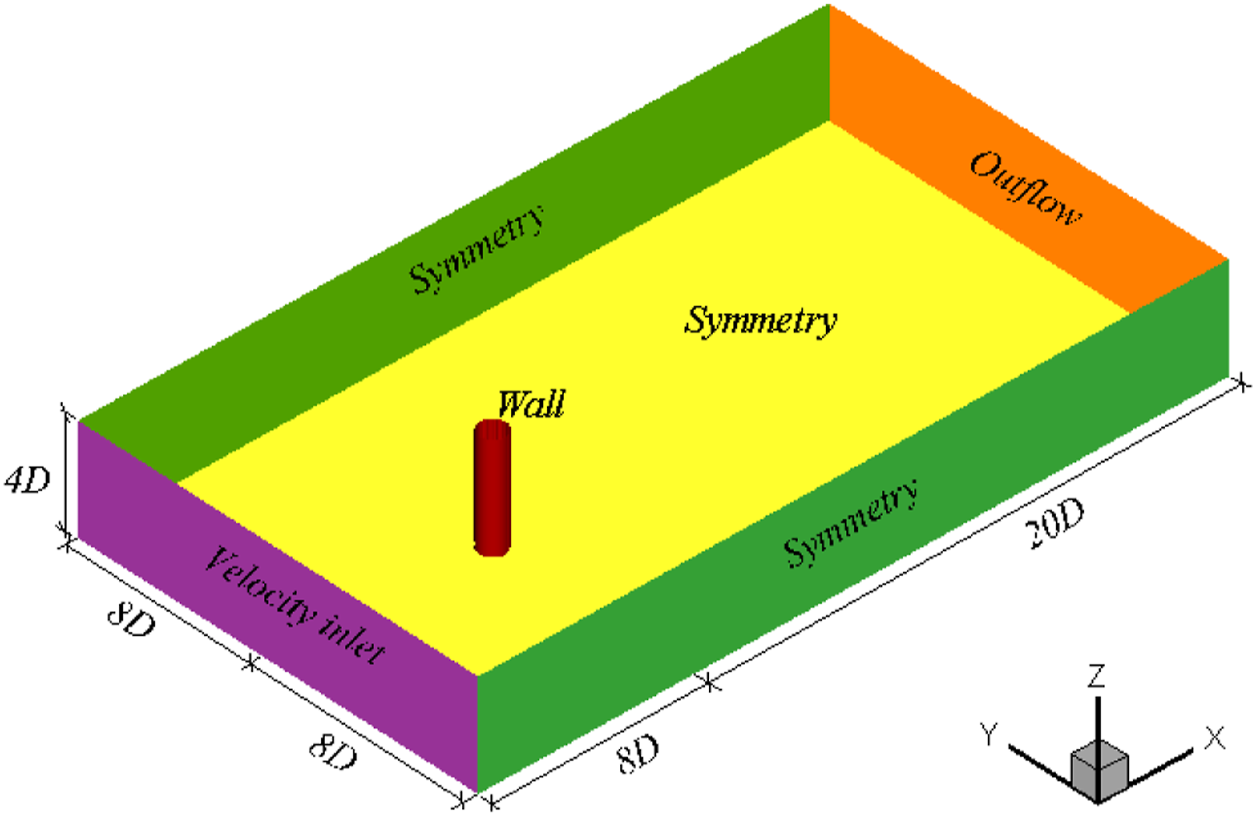
The computational domain is partitioned; the 4D × 4D range centered on the cylinder axis is considered the core refined region, and the rest is the exterior region. The entire computational domain is discretized using a hybrid grid. In the core refined region, structured hexahedral meshes are used inside boundary layers and unstructured tetrahedral meshes are used outside of boundary layers. Structured hexahedral meshes are employed to discretize the external area outside the core refined region. Mesh deformation only occurs within the core refined region, and mesh in the exterior region of the far field is not deformed. Specifically, the dynamic mesh technique is employed to facilitate the flexible deformation of the cylinder surface and enable Fluid-Structure Interaction (FSI). The traveling wave movement on the cylinder surface is achieved through the utilization of a User-Defined Function (UDF) and a grid node motion macro (Define_Grid_Motion). The structured grids within the boundary layers in the refined region deform synchronously with the TWW cylinder surface, while unstructured tetrahedral grids in the refined region undergo remeshing. Thus, the flexible traveling wave motion on the cylinder surface can be realized, and the computational efficiency can be improved. For the core refined region, thin hexahedral mesh elements are used in the boundary layer range of the cylinder surface, and the mesh height of each layer gradually increases from the inside to the outside, with a growth rate of 1.15. In addition, the tetrahedral mesh is used from the outside of the boundary layers to the boundary of the core refined region. During the traveling wave motion of the cylinder surface, the mesh in the boundary layers and the cylinder wall simultaneously undergo flexible deformation. Mesh reconstruction only occurs in the tetrahedral mesh, which ensures the orthogonality of the grid on the cylinder surface and improves the accuracy of calculated results. The meshing of the entire computational domain and the local region around the cylinder is shown in Figure 2. Meshing of the entire computational domain and the local region around the cylinder. (a) Global meshing (midspan section) (b) local meshing (3D view) (c) local meshing (2D view).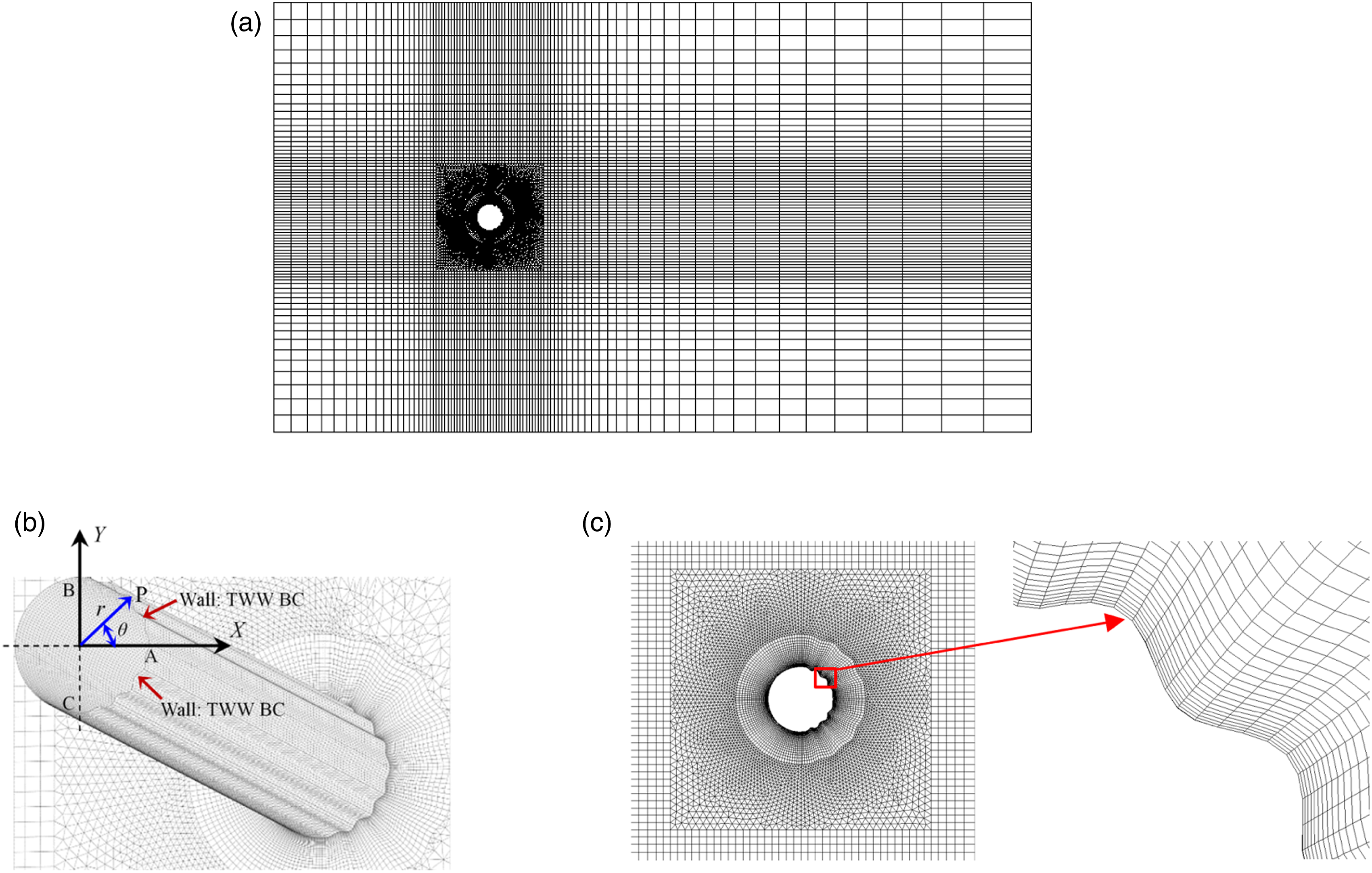
Solution setup and result validation
For the flow around a circular cylinder, vortex shedding occurs on the rear surface of the cylinder. Therefore, the TWW is designed to be set at the rear part of the cylinder. The governing equations for fluid motion and the wave equations of the TWW on the cylinder surface can be found in Xu et al. (2014). The movement of TWW is realized by governing equations of traveling wave and dynamic mesh technology. The wave equations of the TWW on the cylinder surface can be written as
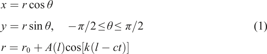
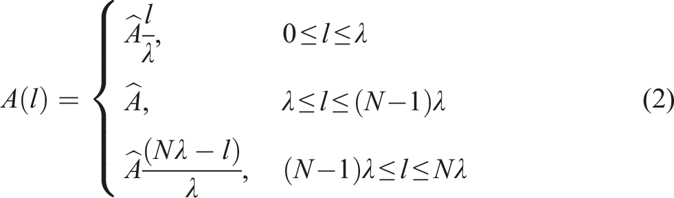
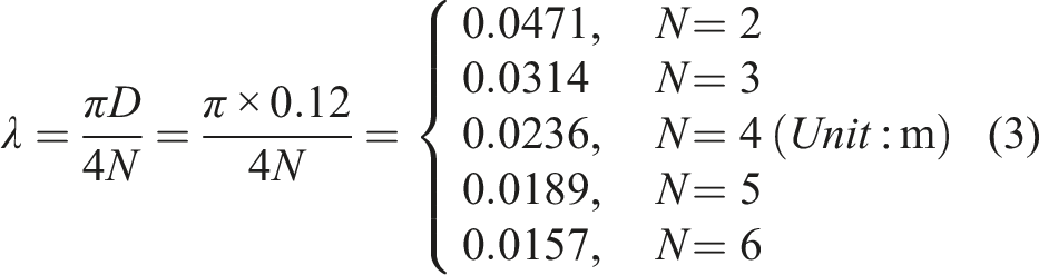
Taking the number of waves N = 4 as an example, the movement pattern of traveling waves is illustrated in Figure 3. As depicted in the schematic diagram, the traveling wave propagates from points B and C to point A. The term ‘N = 4’ indicates the presence of four traveling waveforms along the 1/4 arc on the rear surface of the cylinder. The ratio c/U represents the traveling wave velocity relative to the incoming flow velocity, which is crucial parameter in the TWW control method. On both 1/4 arcs of the rear surface of the cylinder, the traveling wave simultaneously propagates downstream. Within the rear region of the cylinder, all grid node positions are calculated using equation (1), while equation (2) is exclusively employed to control the amplitude of each traveling wave. This ensures a smooth connection of boundaries at positions A, B, and C. Schematic diagram of traveling wave motion on a cylinder surface.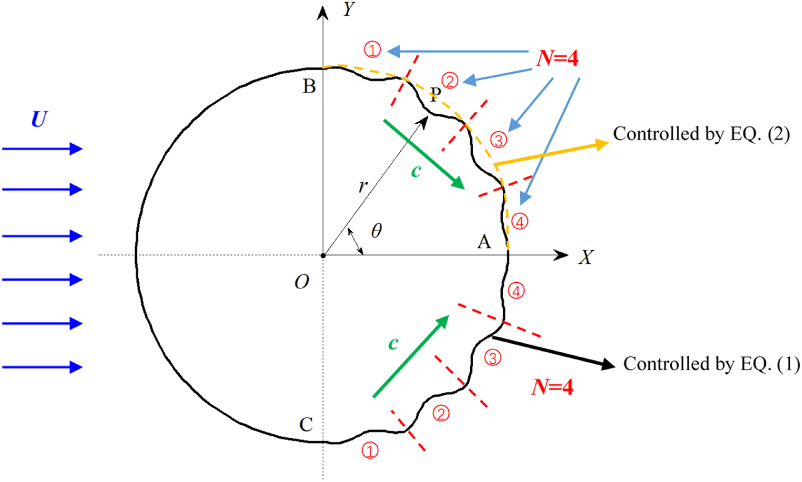
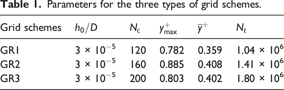
The flow field calculations are performed at a high Reynolds number of
Parameters for the three types of grid schemes.
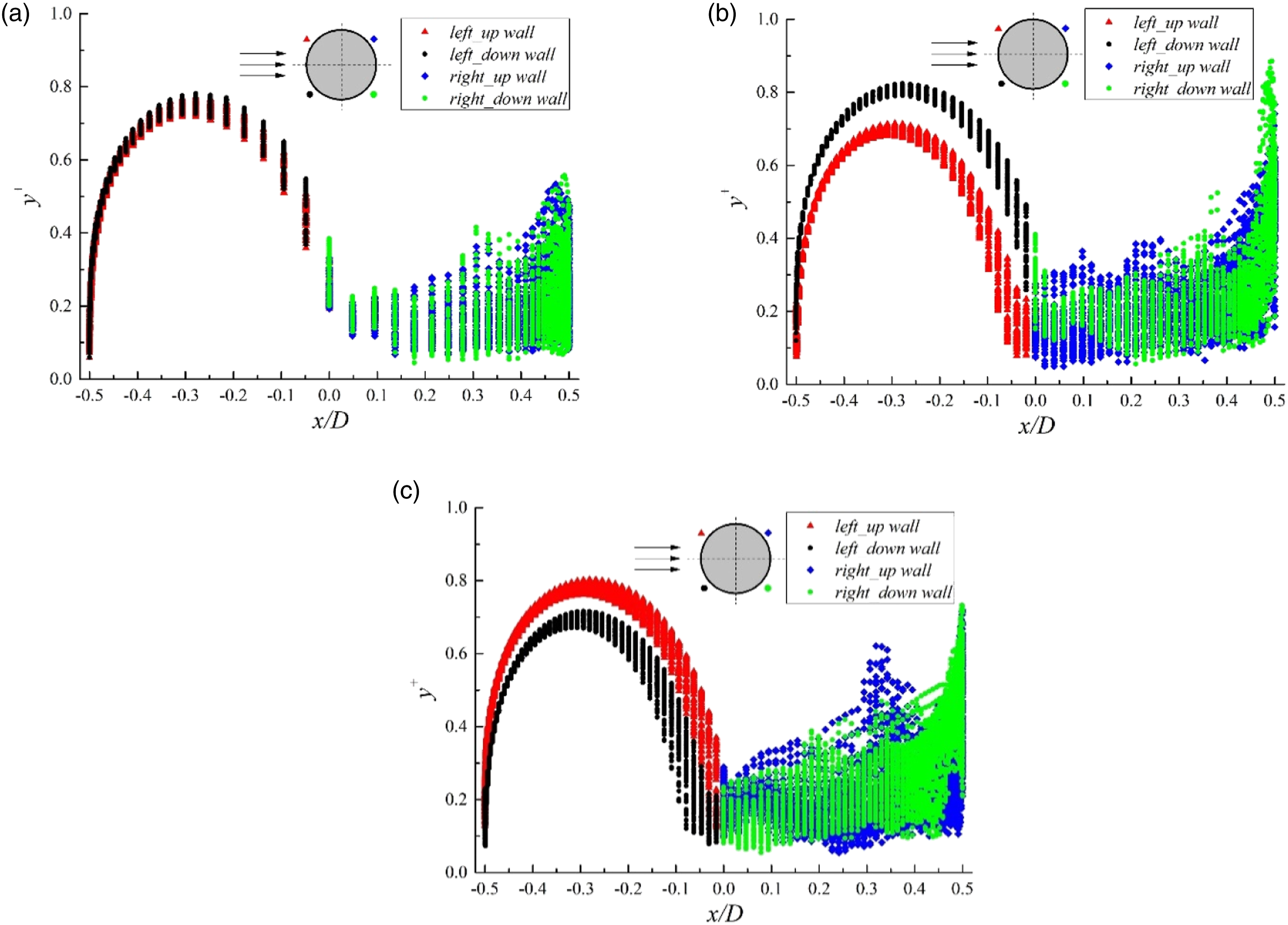
Distribution of
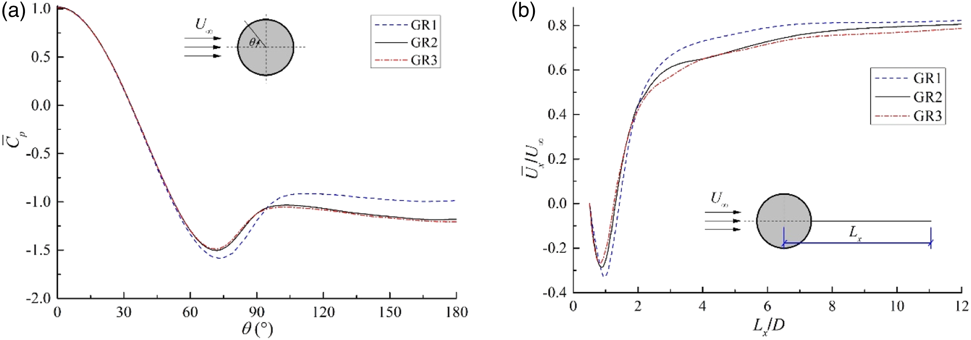
Figure 5 presents the results of time history and spectral analysis of the aerodynamic force for uncontrolled flow around a standard cylinder using the three grid schemes. Time history and spectrum analysis of cylinder lift and drag coefficient under different grid schemes. (a) GR1 (b) GR2 (c) GR3. Mean pressure coefficient distribution at the cylinder midspan section and the time-averaged velocity distribution at the wake centerline for different grid schemes. (a) Mean pressure coefficient distribution at the cylinder midspan section (b) time-averaged velocity distribution at the wake centerline.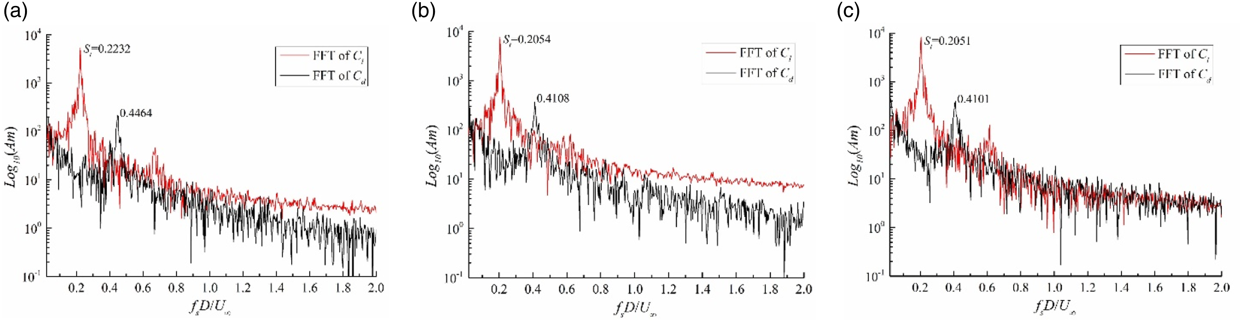
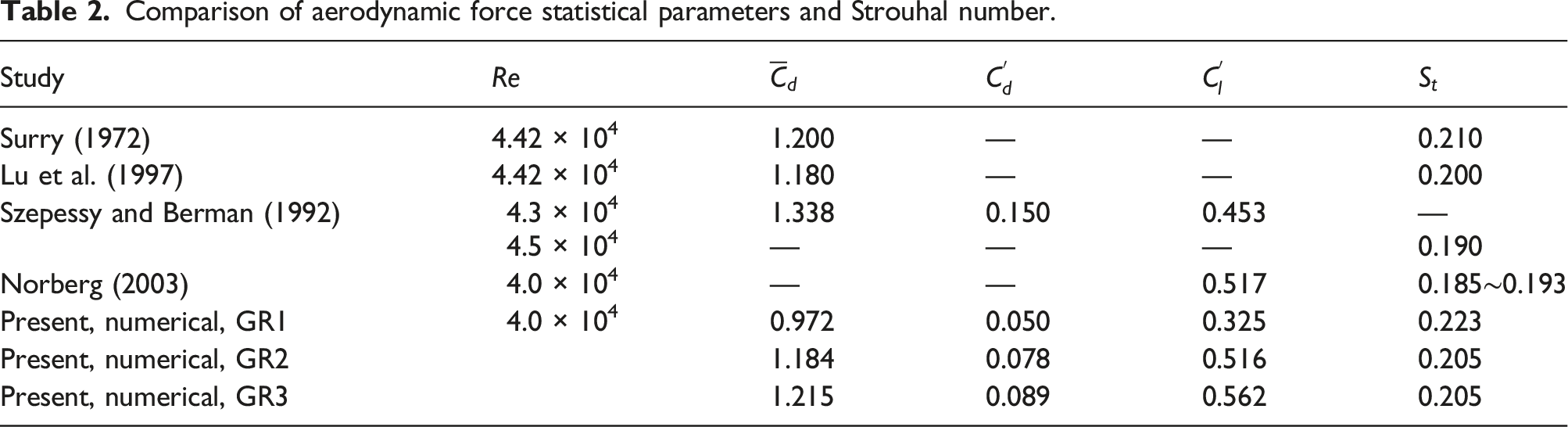
Comparison of aerodynamic force statistical parameters and Strouhal number.
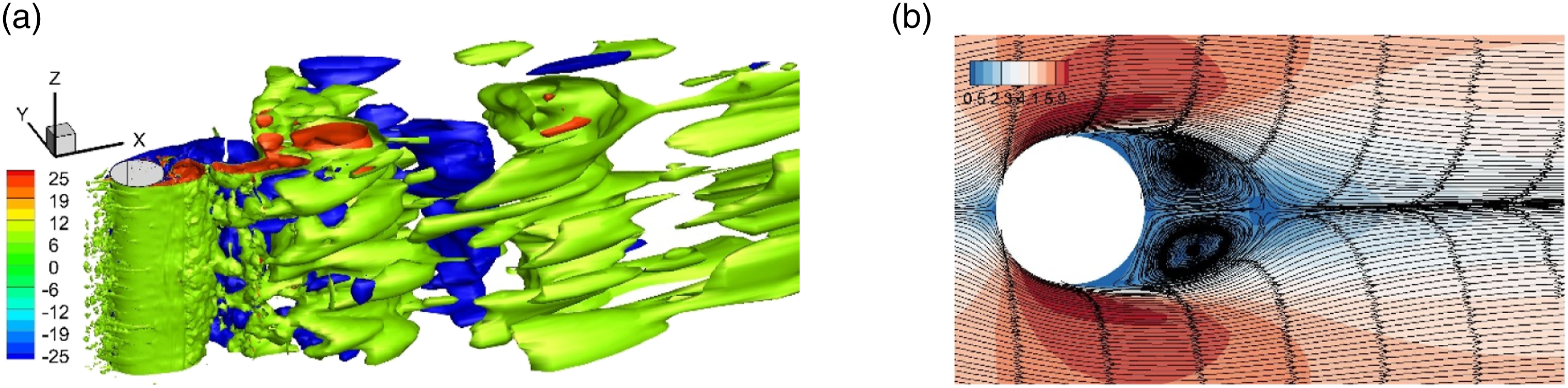
3D instantaneous vortex structure and time-averaged velocity contours and streamlines at the midspan section of the uncontrolled standard cylinder wake. (a) Instantaneous vortex contours (b) time-averaged velocity contours and streamlines at the midspan section.
Results and discussion
The main parameters of TWW flow control include the propagation direction of the traveling wave, wave amplitude
Influence of wave amplitude on control effects
The rear half of the 3D cylinder surface was set as the flexible TWW. The number of traveling waves on each 1/4-cylinder surface N was set as 4, and the ratio of wave velocity to incoming velocity
Figure 8 shows the time history of cylinder lift and drag coefficients under different wave amplitudes. Compared the flow around the uncontrolled cylinder, the time history of the lift and drag coefficients for the TWW cylinder differ noticeably. When the wave amplitude is small ( Time history of lift and drag coefficients for the TWW cylinder with different wave amplitudes. (a) 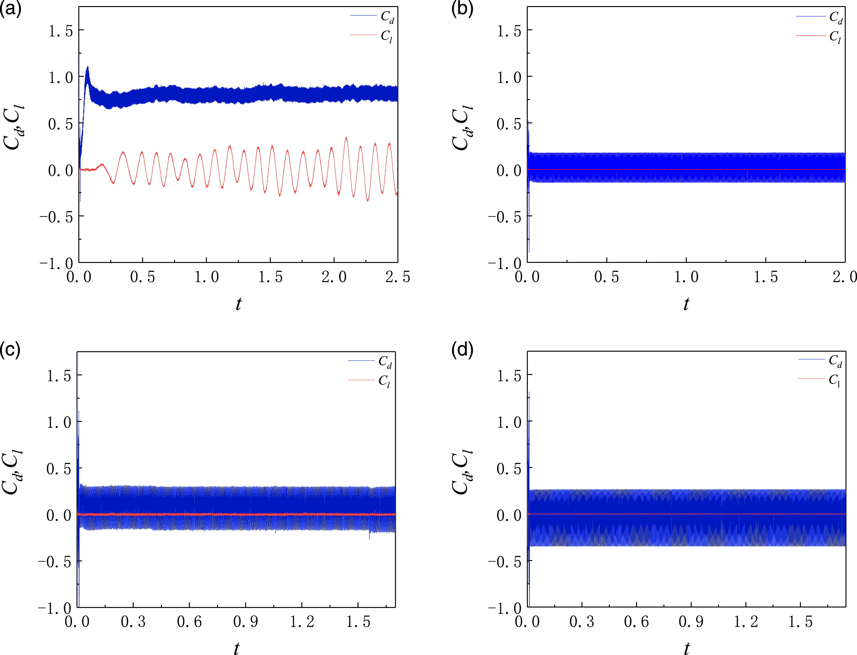
The aerodynamic force time histories of the TWW cylinder under the four wave amplitudes are statistically analyzed. The mean value Statistical value of lift and drag coefficients for the TWW cylinder with different wave amplitudes. (a) 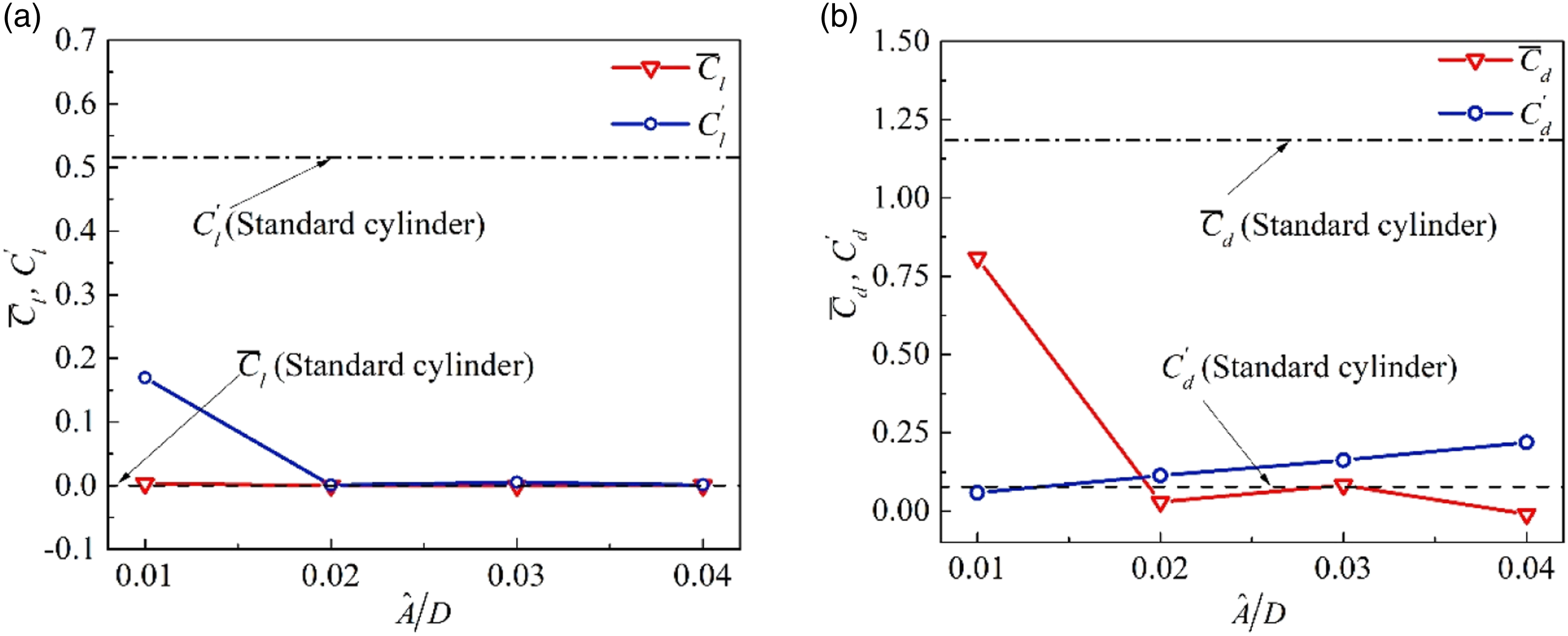
As is evident from Figure 9(a), the lift coefficient mean value
The statistical results of the mean and RMS values of the drag coefficient are presented in Figure 9(b). Evidently, the drag coefficient mean value
The aerodynamic forces acting on the cylinder surface originate from the generation and evolution of the vorticity on the wall and in the wake field. When the wave amplitude affects the change in the cylinder aerodynamic coefficient, the vorticity around the cylinder also changes significantly. Figure 10 shows the instantaneous 3D vortex structure and vorticity contours at the midspan section of the TWW cylinder wake under different wave amplitudes. Here, red indicates positive vorticity with counterclockwise rotation, and blue indicates negative vorticity with clockwise rotation. Time-averaged velocity contours and streamlines at the midspan section of the TWW cylinder under different wave amplitudes are shown in Figure 11. Instantaneous 3D vortex structure and vorticity contours at the midspan section in the TWW cylinder wake for different wave amplitudes. (a) Time-averaged velocity contours and streamlines at the midspan section of the TWW cylinder for different wave amplitudes. (a) 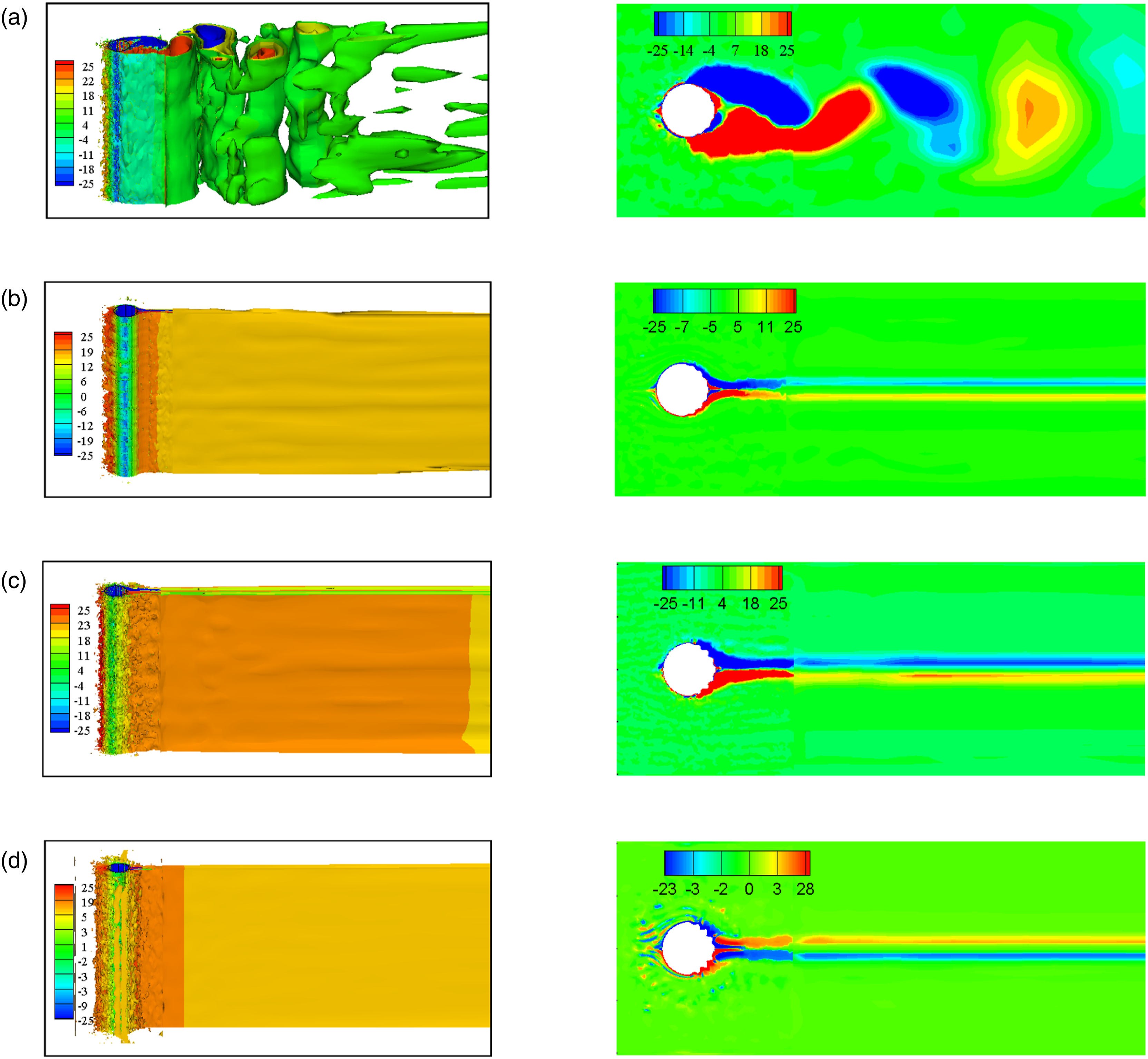
As shown in Figure 10(a), when
Influence of number of waves on control effect
The amplitude ratio Time history of the lift and drag coefficients of the TWW cylinder for different number of waves. (a) 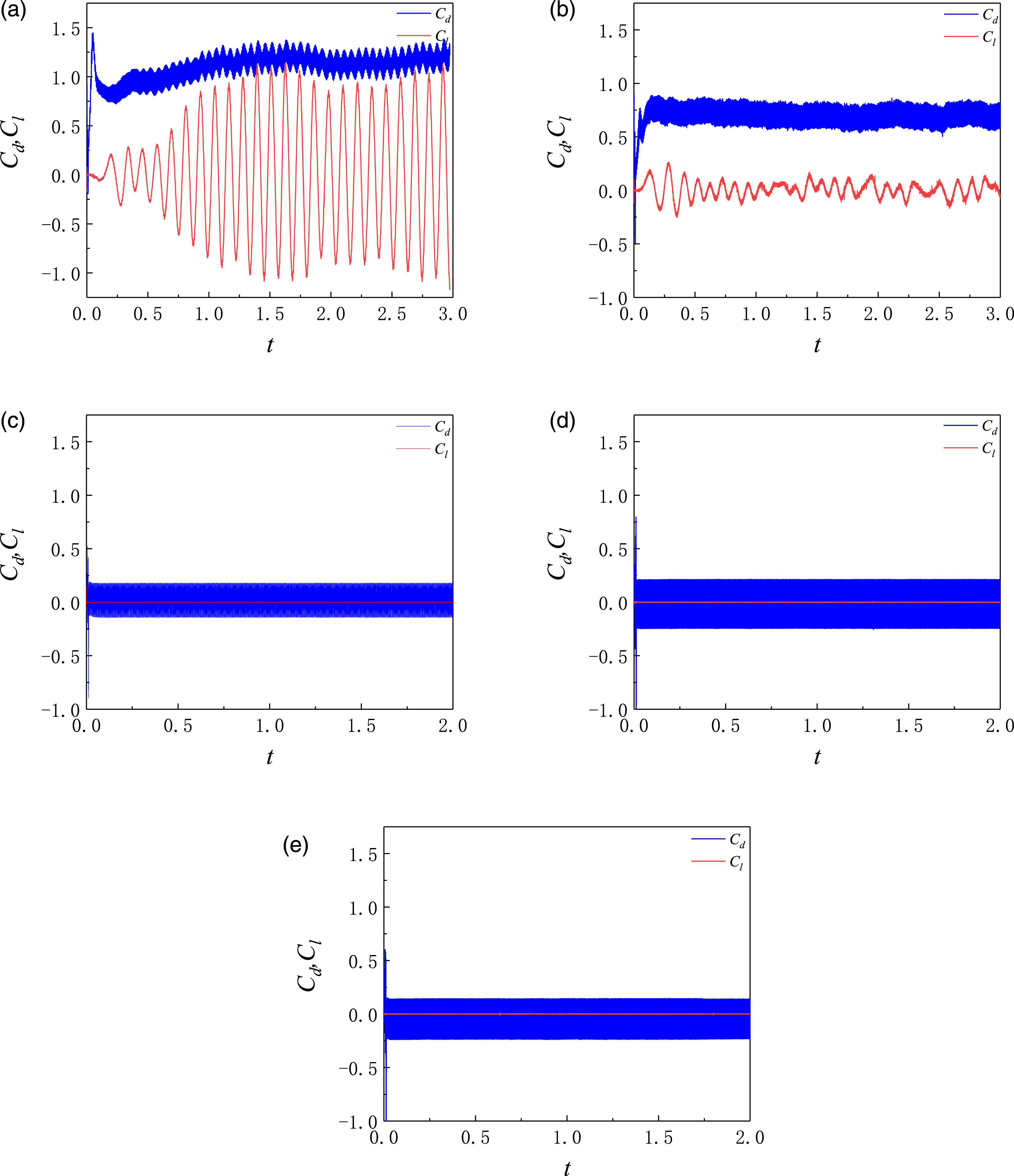
As shown in Figure 12(a), when the number of waves
The aerodynamic force time histories of the TWW cylinder are statistically analyzed at five different number of waves, and the curves of the mean value Statistical value of the lift and drag coefficient for the TWW cylinder with different number of waves. (a) 
Figure 14 shows the instantaneous 3D vortex structure and vorticity contours at midspan section in the TWW cylinder wake with different number of waves. As shown in Figure 14(a), when Instantaneous 3D vortex structure and vorticity contours at the midspan section in the TWW cylinder wake with different number of waves. (a) 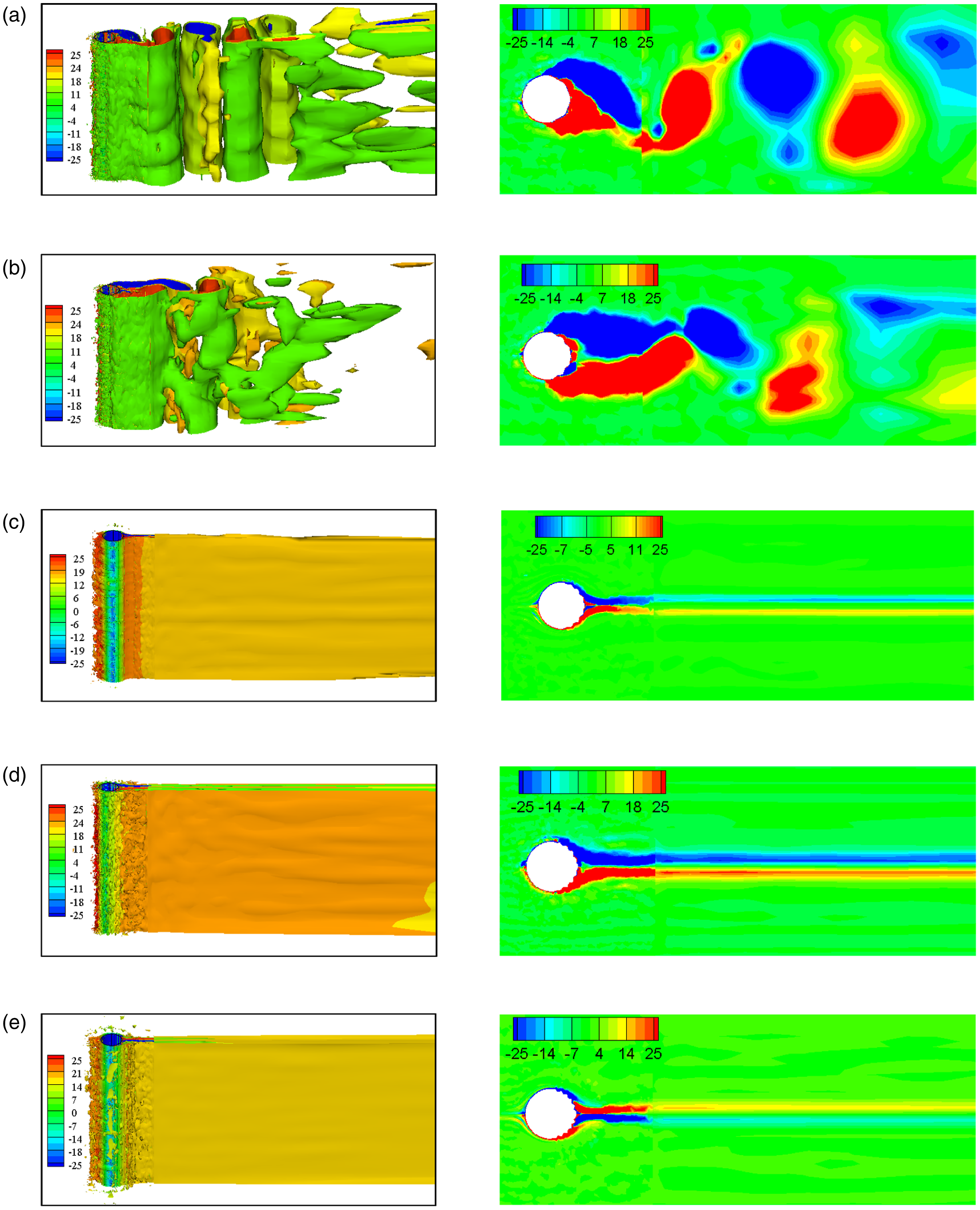
Figure 15 shows the time-averaged velocity contours and streamlines at the midspan section of the TWW cylinder with different number of waves. When Time-averaged velocity contours and streamlines at the midspan section of the TWW cylinder with different number of waves. (a) 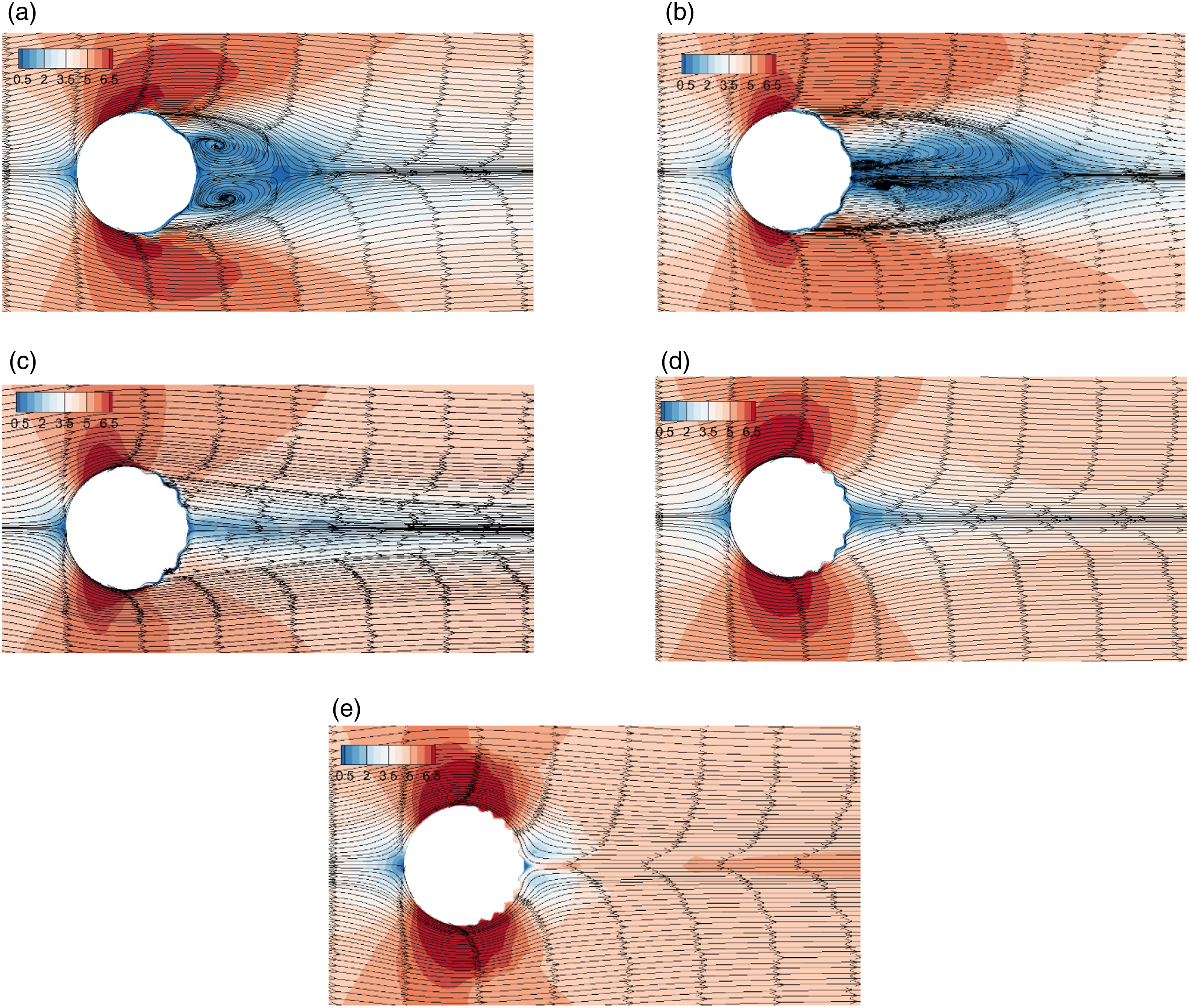
Influence of wave velocity on control effect
To study the influence of wave velocity on the control effect of the cylinder wake, the number of waves N on the quarter cylinder surface is set to 4, and the ratio of the maximum wave amplitude to the cylinder diameter Time histories of the lift and drag coefficient for the TWW cylinder with different wave velocities. (a) 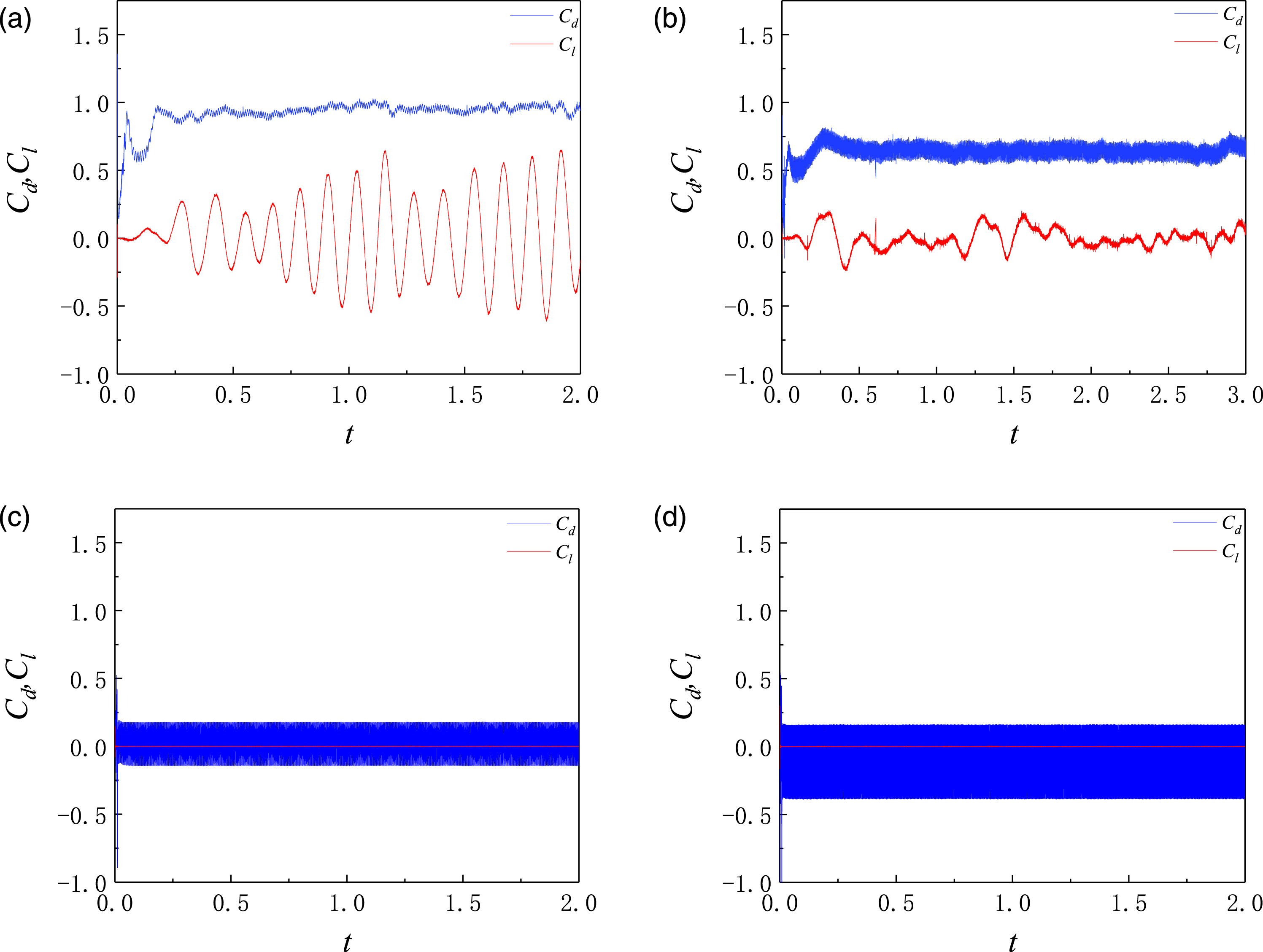
When the number of waves N is 4, the corresponding wavelength Spectral analysis of the drag coefficient for the TWW cylinder with different wave velocities. (a) 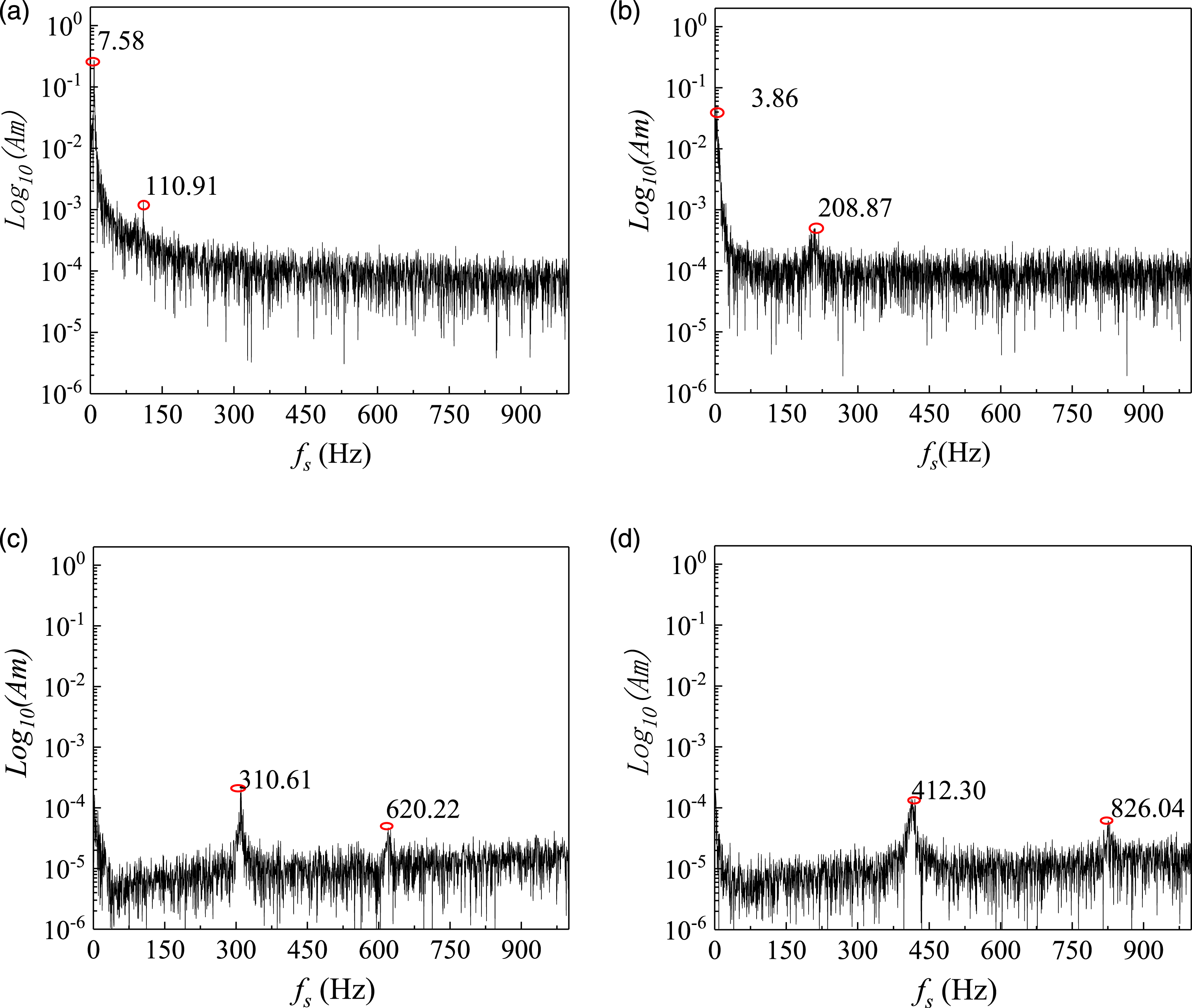
To further analyze the variation law of cylinder aerodynamic force with different velocity ratios, the lift and drag coefficient mean values ( Statistical values of the lift and drag coefficient for the TWW cylinder with different wave velocities. (a) 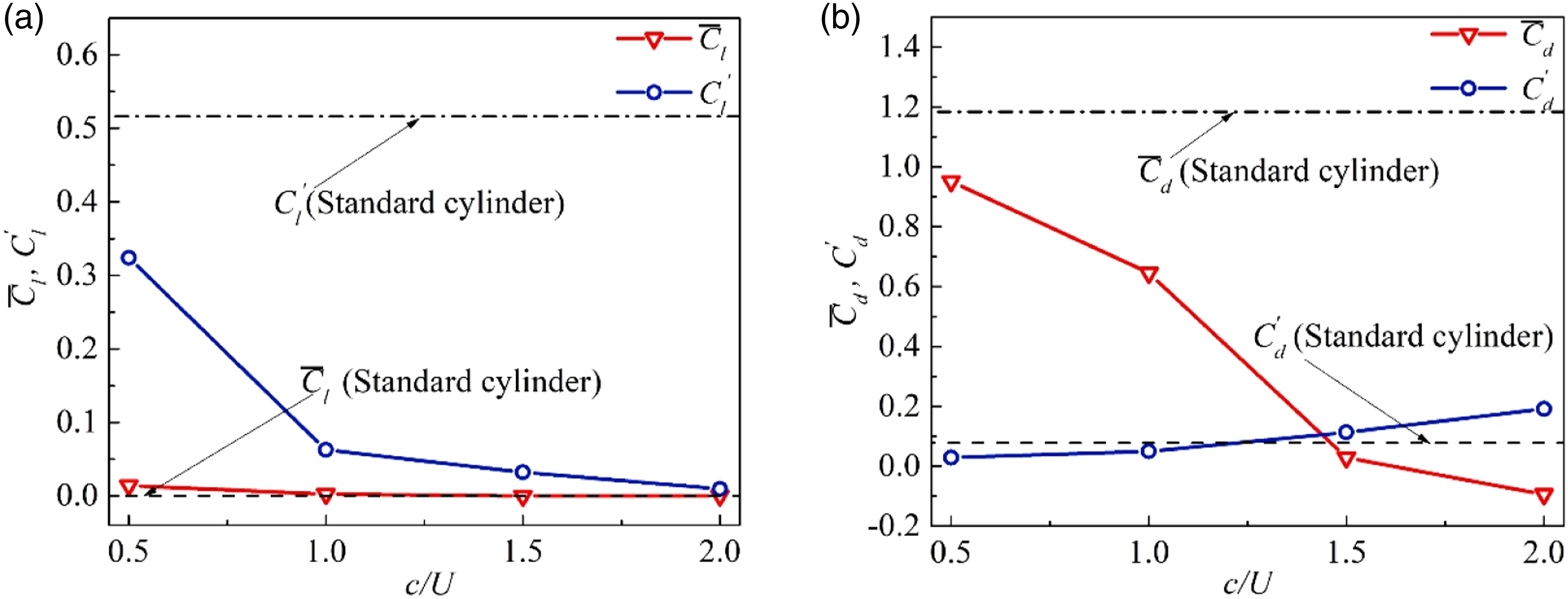
The change in the cylinder aerodynamic characteristics originates from the change in the vortex structure and vortex shedding mode in the flow field. The instantaneous 3D vortex structure and vorticity contours at the midspan section in the TWW cylinder wake with different velocity ratios are shown in Figure 19. When Instantaneous 3D vortex structure and vorticity contours at the midspan section in the TWW cylinder wake with different wave velocities. (a) 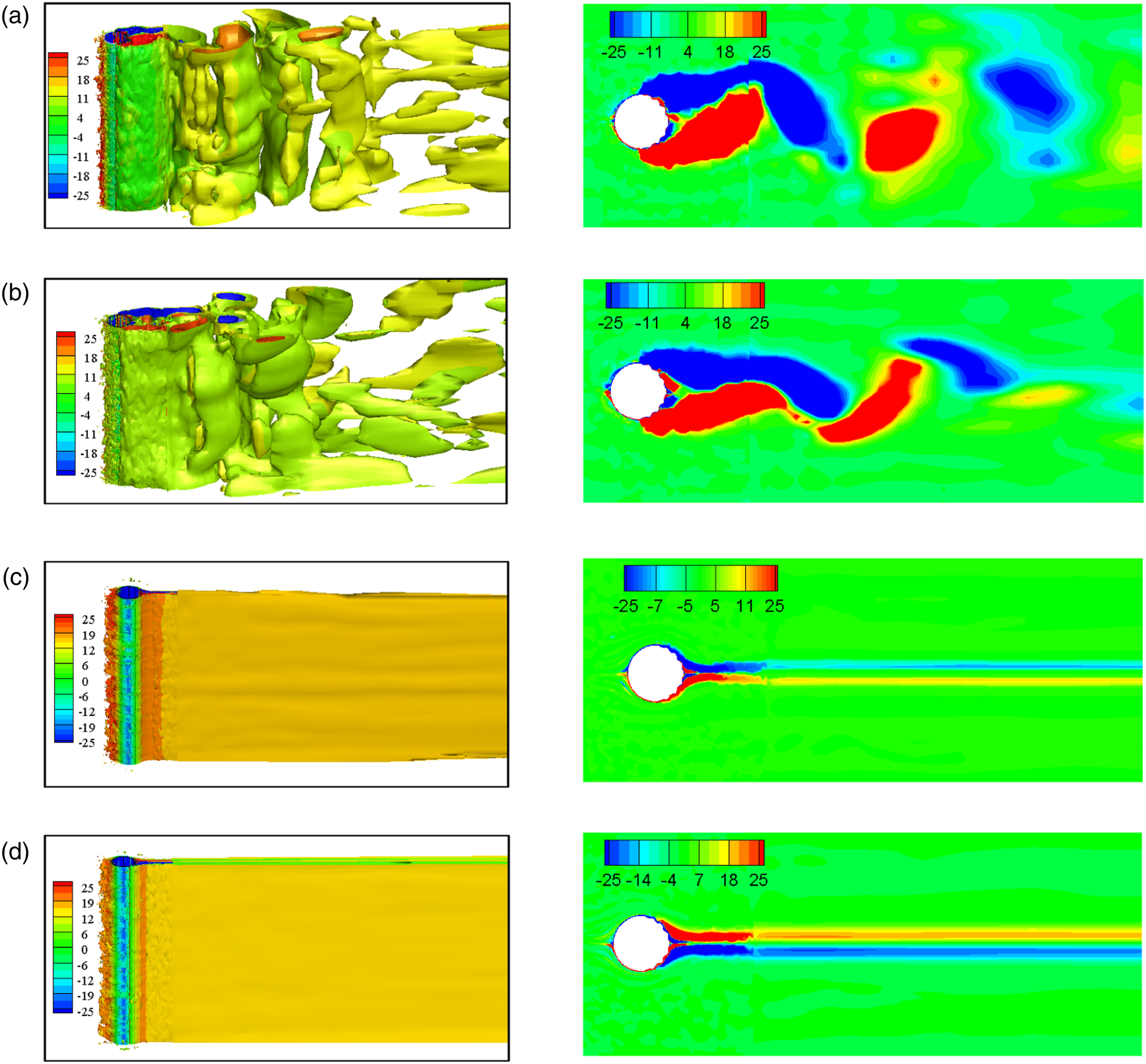
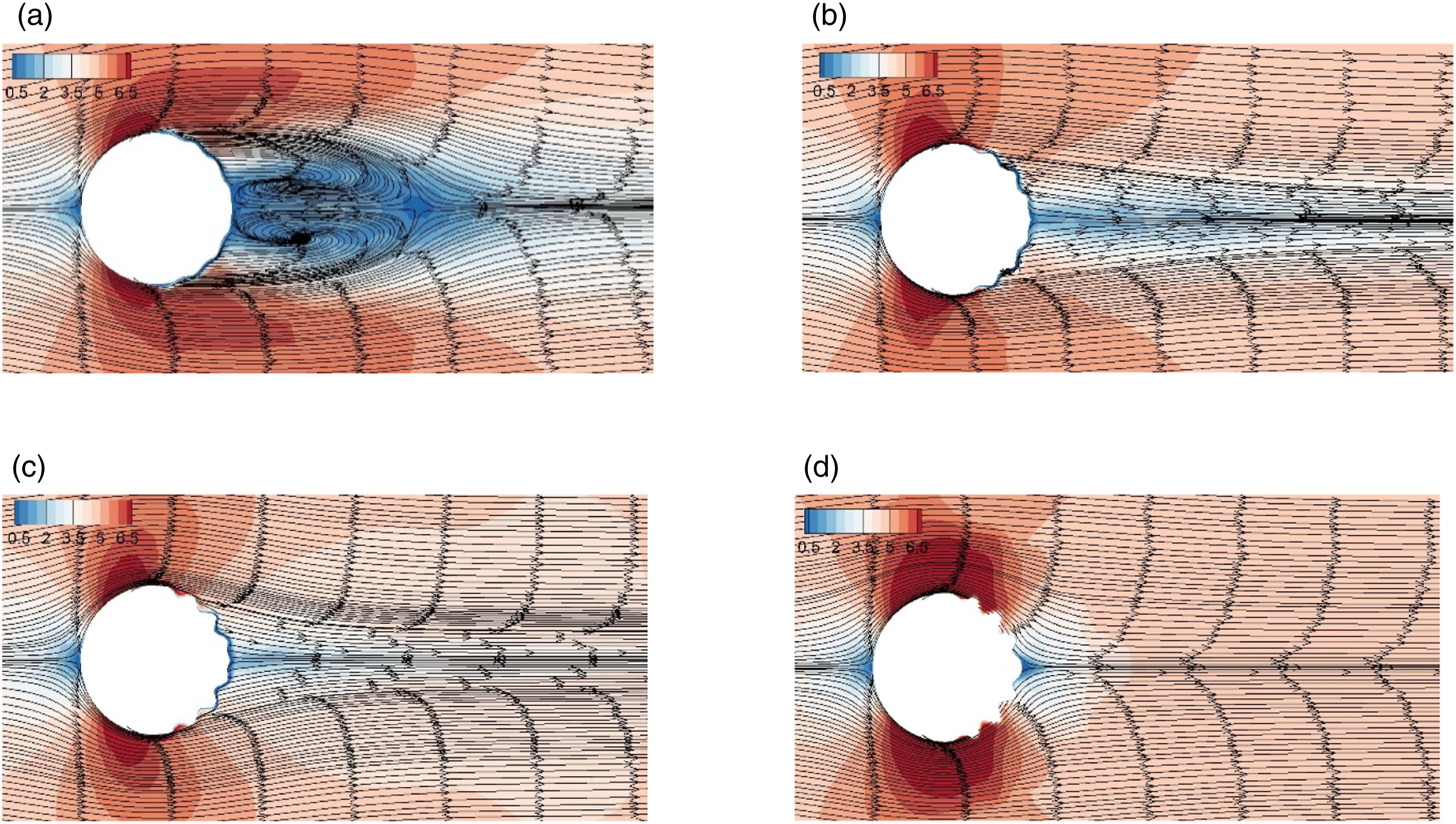
The time-averaged velocity contours and streamlines at the midspan section of the TWW cylinder with different velocity ratios are shown in Figure 20. When Time-averaged velocity contours and streamlines at the midspan section of the TWW cylinder with different wave velocities. (a) 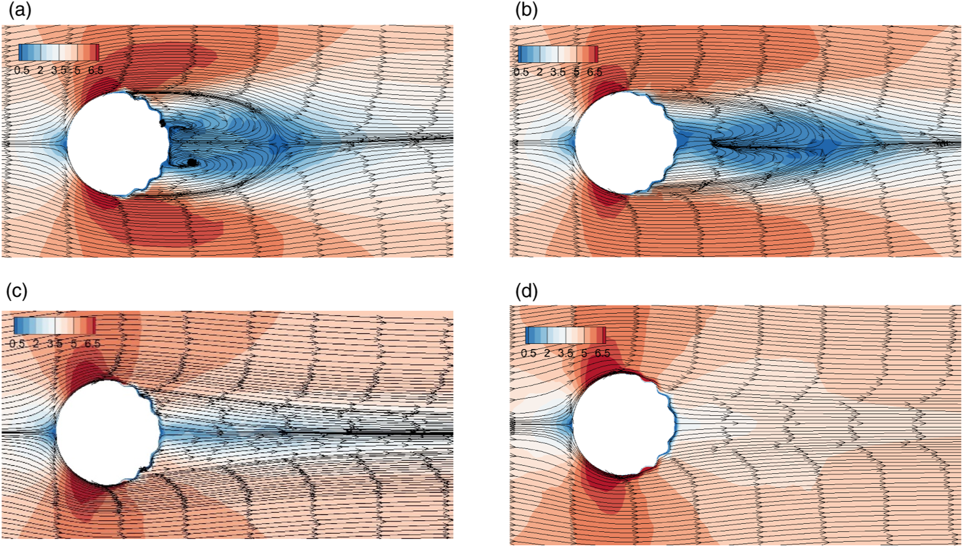
Conclusions
In this study, LES is used to examine the TWW flow control method for 3D cylinder wake, and the influence laws of the main control parameters of the traveling wave on the aerodynamic force of the 3D cylinder are analyzed. The main conclusions are as follows. 1. For the calculation with high Reynolds number in this study, the optimal control parameter combination can be obtained through the control effect of the TWW on the cylinder aerodynamic force, that is, the ratio of traveling wave maximum amplitude to cylinder diameter is 0.02, the number of waves of the traveling wave is 4, and the ratio of wave velocity to incoming velocity is 1.5. 2. With the optimal control parameter combination, the backflow in the near-wake region of the TWW cylinder completely disappears, and the streamlines no longer curl and gradually become straight. The low-velocity region and negative pressure region in the cylinder wake gradually decrease, so the drag coefficient mean value in the downwind direction also decreases significantly. The drag coefficient fluctuation value increases significantly, but its high-frequency fluctuation originates from the disturbance frequency induced by the traveling wave motion, which reflects the active control characteristic of the TWW method. 3. With the optimal control parameter combination, the TWW control method completely eliminates the 3D flow characteristic in the spanwise direction of the cylinder, the complex 3D vortex structure in the cylinder wake region disappears, and the instantaneous vorticity at the cylinder midspan section is strap-shaped and distributed symmetrically and stably on both sides of the wake centerline. The lift coefficient fluctuation of the TWW cylinder disappears completely, approaching a straight line with a mean value of zero and achieving the purpose of eliminating the alternating vortex shedding in the 3D cylinder wake and suppressing the vortex-induced vibration.
Footnotes
Declaration of conflicting interests
The author(s) declared no potential conflicts of interest with respect to the research, authorship, and/or publication of this article.
Funding
The author(s) disclosed receipt of the following financial support for the research, authorship, and/or publication of this article: This research was funded by the National Key Research and Development Program of China (2021YFC3100702), the National Natural Science Foundation of China (NSFC) (52078175, 51778199), the Natural Science Foundation of Guangdong Province (2019A1515012205), the Fundamental Research Funds of Shenzhen Science and Technology Plan (JCYJ20190806144009332), the Shenzhen Science and Technology Program (KQTD20210811090112003), and the Stability Support Program for Colleges and Universities in Shenzhen (GXWD20201230155427003-20200823134428001).