
Abstract
Rib-to-deck (RTD) innovative double-sided welded joints have the potential to enhance the fatigue resistance of orthotropic steel decks (OSDs). However, welding residual stress (WRS) has been reported to be a contributing factor to fatigue cracking of steel bridges. This paper performed fatigue crack growth of the RTD innovative double-sided welded joints of OSD considering WRS. Firstly, a thermal-mechanical sequential coupling finite element model (FEM) of the RTD double-sided welded joints was established. The WRS distribution along the direction of deck thickness was analyzed. Secondly, the FEM of the OSD segment with crack was established. The fatigue crack behavior of RTD double-sided welded joints under the combined action of vehicle load and WRS was studied. Finally, the influences of initial crack on fatigue life was analyzed. Results indicate the distribution of the transverse WRS along the direction of deck thickness is tension-compression-tension stress, which has the characteristics of the sinusoidal function. The ∆Keff value increases significantly considering WRS than without considering WRS during crack growth. WRS has a significant effect on fatigue life, and the fatigue life of the weld toe without considering WRS is about twice that of considering WRS. The crack depth and aspect ratio (a0/c0) of the initial crack affect the fatigue life of RTD double-sided welded joints.
Keywords
Highlights
(1) A method for fatigue crack growth of rib-to-deck double-sided welded joints in OSD for the effects of residual stresses was presented. (2) The WRS distribution of the rib-to-deck double-sided welded joints was fitted by sinusoidal function. (3) Fatigue crack growth behavior of rib-to-deck double-sided welded joints of OSD was simulated with or without the effect of WRS. (4) Fatigue life evaluation integrated with the effect on WRS was performed for the rib-to-deck double-sided welded joints.
Introduction
Orthotropic steel decks (OSDs) are widely used in long-span steel box girder cable-stayed bridges and suspension bridges due to their advantages of lightweight, high strength, ease of prefabrication and speedy construction, among other benefits (Zhuang et al., 2022; Wang et al., 2020). However, due to significant welding residual stress (WRS), welding defects, and increases in traffic load over time, fatigue cracking of existing OSD has continuously occurred during its service life (Cui et al., 2018; Zhu et al., 2020; Song et al., 2016). Fatigue crack defects have been observed in rib-to-deck (RTD) conventional single-sided welded joints in serviceable OSD. Based on a review of fatigue cracks occurring in these joints (Wang et al., 2019; Fisher et al., 2015), four failure modes of fatigue cracking have been identified: root-deck, toe-deck, toe-trough, and root-throat. The fatigue issues associated with RTD welded joints of OSD directly threaten the safety and durability of the structure.
With the development of advanced internal welding technology, the RTD innovative double-sided welded joints have been proposed (Yang et al., 2022), as shown in Figure 1. The RTD innovative double-sided welded joints has brought a new opportunity to solve the fatigue cracking of RTD welded joints of OSD. RTD innovative double-sided welded joints are formed by adding a fillet weld inside the U-rib through intelligent robot automatic welding technology, on the basis of RTD conventional single-sided welded joints. Compared with the RTD conventional single-sided welded joints, the RTD innovative double-sided welded joints are welded at the interior and exterior of the joint to improve the fatigue resistance of welded joints. Firstly, the bilateral fillet welds increase the cross-sectional area of the RTD connection weld and improve local weld stiffness. Secondly, the bilateral fillet welds are aligned with the center of the U rib, which changes the eccentricity of the weld to the U-rib and avoids the cracking of the weld root. Finally, the bilateral fillet welds transform the incomplete penetration area of the weld root into a closed rigid area to avoid propagation of crack-like defects generated by the RTD conventional single-sided welded joints under cyclic loading. Practical application of RTD innovative double-sided welded joints has been successful in bridge construction projects in China, making this a current research hot spot (Zhang et al., 2019a; Chen et al., 2023). RTD innovative double-sided welded joints.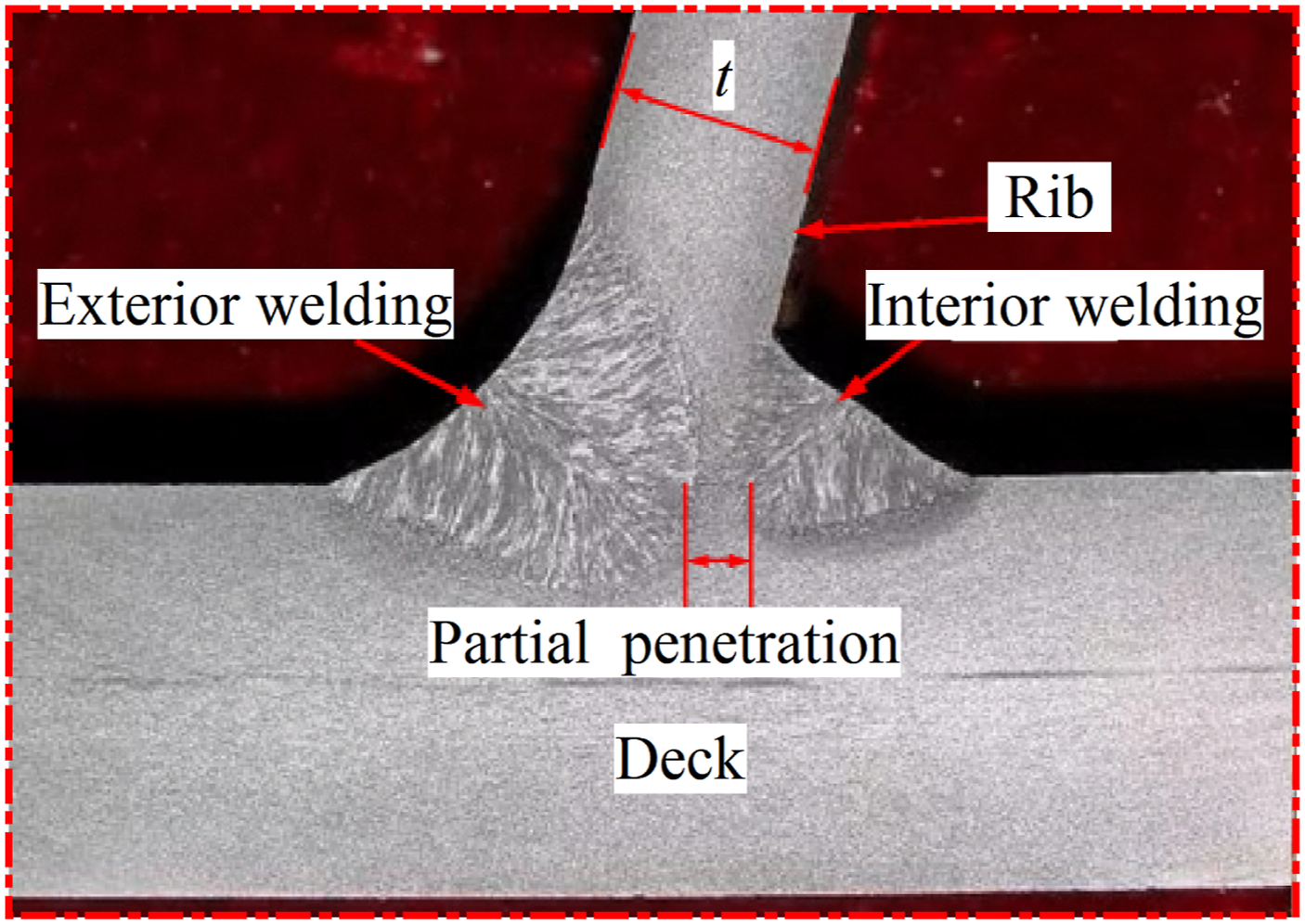
Recently, researchers have conducted experimental and theoretical studies on fatigue performance and fatigue crack growth of the RTD innovative double-sided welded joints of OSD. You et al. (2018) and Zhang et al. (2021a) conducted tests on full-scale OSD models fabricated with RTD single-sided and double-sided weld joints. It was found that the double-sided welded joints provided significantly higher fatigue life than the single-sided welded joints. Yang et al. (2022) conducted experimental and numerical investigations of the fatigue resistance properties of RTD single-sided and double-sided welded joints using the traction structural stress method. Zhang et al. (2019a) and Liu et al. (2021) explored the fatigue crack growth behavior of the RTD double-sided welded joints of OSD using the finite element method (FEM) and linear elastic fracture mechanics, and found that the fatigue crack growth was a mixed mode dominated by opening-mode (type I). Furthermore, Fang et al. (2020) evaluated the notch stress at the weld details of RTD double-sided welded joints by FEM, and discussed the factors that influence the fatigue failure mode of these joints. Additionally, Zhang et al. (2019b) investigated the fatigue performance of the RTD double-sided welded joints of OSD by employing the equivalent structural stress method. It was found that the predominant fatigue failure of RTD double-sided welded joints is the crack that initiates at the weld toe and grows through the deck plane.
In addition, the double-sided welding process with multiple passes can result in complex WRS distribution at the weld heat-affected zone of RTD double-sided welded joints (Zhang et al., 2021). This type of WRS is considered one of the main factors contributing to fatigue cracking of steel bridges (Gadallah et al., 2020; Gu et al., 2020; Cheng et al., 2017). Therefore, researchers have conducted experimental and theoretical studies on the WRS and its distribution at RTD double-sided welded joints of OSD. Zhang et al. (2021b) and Cui et al. (2019) utilized ultrasonic methods and FEM simulation techniques to measure the WRS at RTD double-sided welded joints. Qiang et al. (2020) investigated the distribution of WRS along the thickness direction of RTD double-sided welded joints by performing experimental measurements and numerical simulations, and used the weight function method to explore the effects of WRS on the stress intensity factors (SIFs) of surface crack. The results revealed that transverse WRS had significant effects on SIFs. Liu et al. (2019) investigated the SIF of the RTD double-sided welded joints considering WRS by a FEM, and found that the WRS can significantly influence the SIF values. However, the WRS would affect the fatigue crack growth behavior of RTD double-sided welded joints of OSD is still ambiguous.
This study investigated the fatigue crack growth behavior of the RTD double-sided welded joints of OSD considering the effect of WRS using linear elastic fracture mechanics (LEFM). Firstly, A three-dimensional FEM of RTD double-sided welded joints of OSD is established to obtain the WRS distribution through a thermal-mechanical sequential coupling analysis. Secondly, the FEM of the OSD segment with crack was established by ABAQUS, 2020, FRANC3D, 2020 software. The fatigue crack behavior of RTD double-sided welded joints of OSD was simulated with or without the effect of WRS. Finally, the influences of initial crack depth and aspect ratio (a0/c0) on fatigue life were analyzed.
Details of rib-to-deck double-sided welded joints
In this study, the WRS effects on fatigue crack behavior of RTD double-sided welded joints of OSD were analyzed taking the OSD in Jiayu Yangtze River Bridge in China as an example. Figure 2 shows the details of RTD double-sided welded joints. The thickness of deck, and U-rib is 16 mm, 8 mm, respectively. The size of the U-ribs is 300 mm × 300 mm × 8 mm. The dimensions of the inner and outer welds of the RTD double-sided welded joints are 6 mm and 10 mm, respectively. The deck and U-ribs are connected by double-sided welds with an 80% partial penetration rate, and the clearance between the U-rib and the deck plate assembly is less than or equal to 0.5 mm. Details of RTD double-sided welded joints (unit: mm).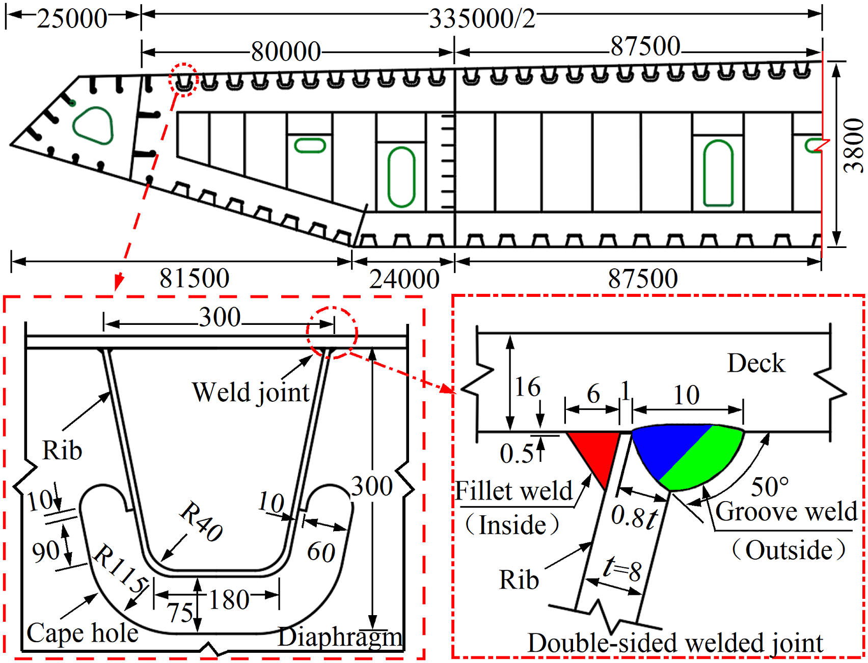
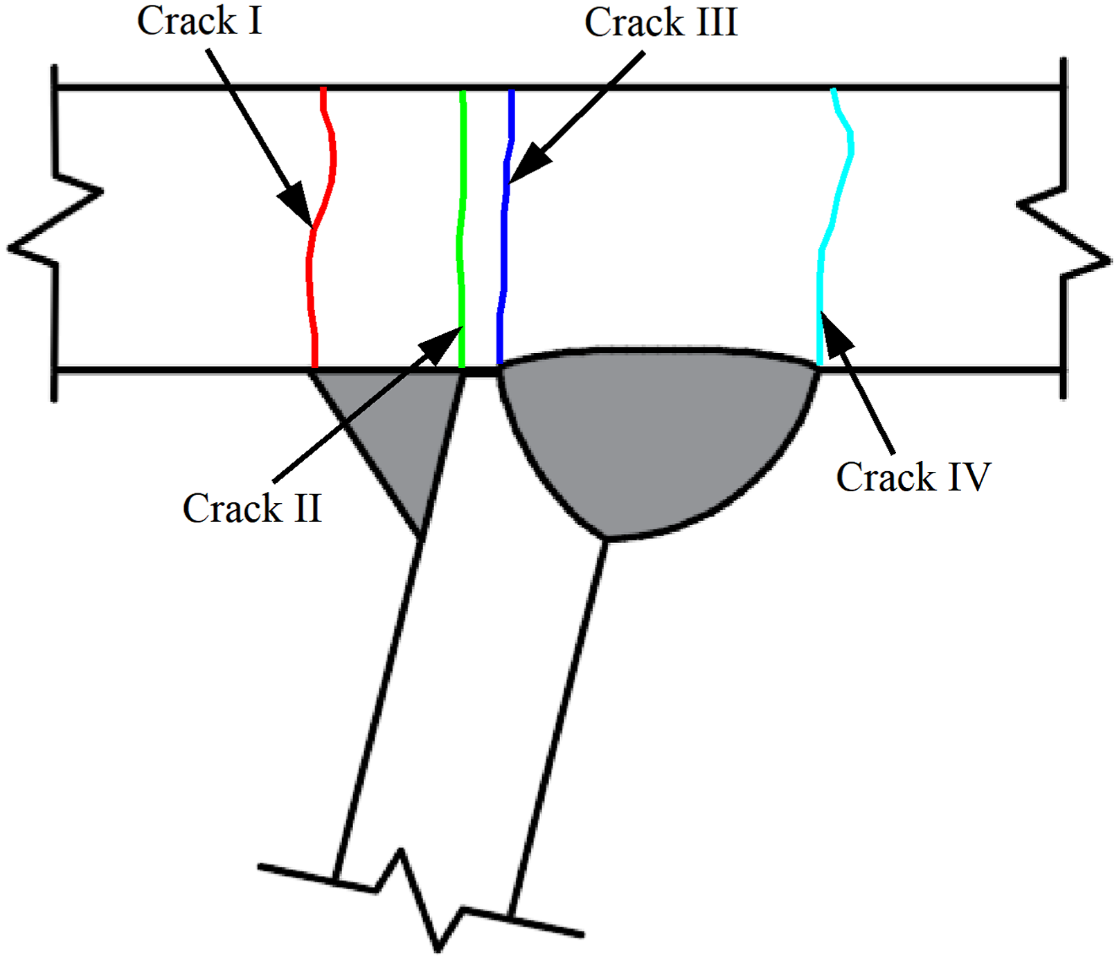
Figure 3 illustrates the typical fatigue crack patterns at the RTD double-sided welded joints of OSD. Among them, the dominating cracks are Crack I, Crack II, Crack III, and Crack IV, which initiate from the weld toe or weld root and propagate through the deck (Zhang et al., 2019b, 2021b). Crack I: outside toe-deck, initiates at the outside weld toe and propagates into the deck. Crack II: outside root-deck, initiates at the outside weld root and propagates into the deck. Crack III: inside root-deck, initiates at the inside weld root and propagates into the deck. Crack IV: inside toe-deck, initiates at the inside weld toe and propagates into the deck. Typical crack patterns at the welded joints.
Flow of fracture analysis considering WRS
Figure 4 illustrates the proposed procedure for predicting fatigue crack growth in RTD double-sided welded joints of OSD considering the effect of WRS. The procedure is comprised of three parts. In the first part, the WRS is simulated through the establishment of a FEM in ABAQUS. The thermal-mechanical sequential coupling method (Cui et al., 2019), i.e., the temperature field is initially simulated and then set as the predefined condition for mechanical analysis, was adopted in this research. The WRS values at initiation points along the direction of deck thickness are obtained by mechanical analysis. The second part involves the establishment of a FEM for fracture analysis. Initially, an uncracked FEM is established in ABAQUS and subsequently imported into FRANC3D to establish a local sub-model. Subsequently, an initial semi-elliptical surface crack is inserted at the weld root or weld toe of the local sub-model using FRANC3D and re-meshed to establish a cracked local sub-model. In the third part, the WRS is introduced as the initial stress in the cracked sub-model. Subsequently, the SIF and fatigue crack propagation caused by the applied fatigue loading and WRS are calculated. Procedure for fatigue crack propagation prediction.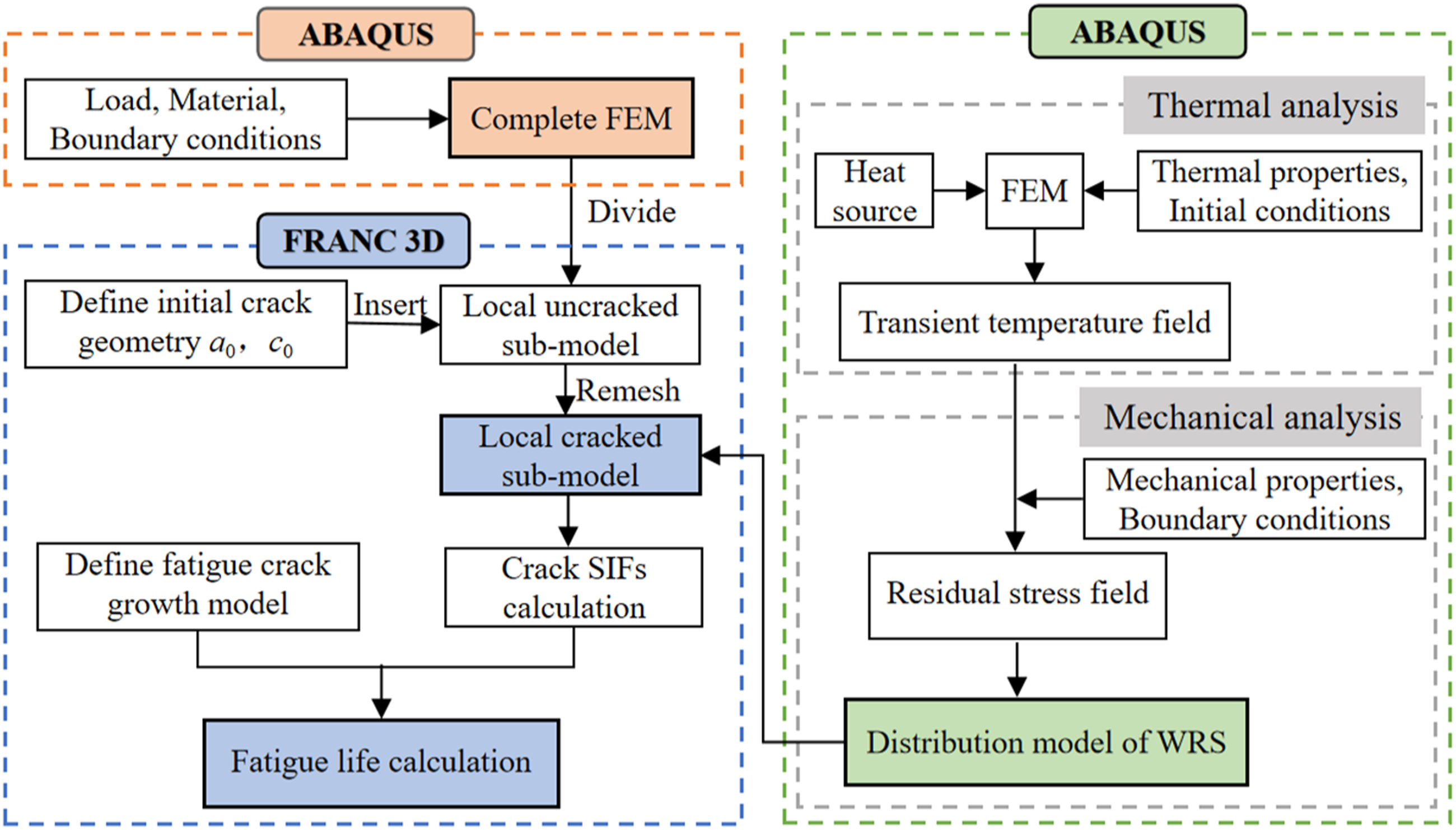
Welding numerical simulation
Description of the FEM of WRS
The thermal-mechanical sequential coupled FEM was developed by ABAQUS to calculate the temperature field, WRS of RTD double-sided welded joints of OSD. Figure 5 shows the dimensions of the FEM. The global and local mesh sizes are determined by mesh size convergence analysis. The global mesh size is 10 mm, and the refined mesh size in the vicinity of the welded joints is 1 mm. In thermal analysis, the DC3D8 element type are employed in heat transfer analysis. In the welding process of RTD double-sided welded joints, the element birth-death method is developed using Python script files to simulate the filling of cladding metal materials of multi-pass welds. The ambient temperature is assumed to be constant at 20°C. In terms of thermal boundary conditions, the effects of both convection and radiation are modeled with consideration of the heat loss on the surface of the RTD welded joints. In mechanical analysis, the same FEM as that used in thermal analyses is used, except for the element type and boundary conditions. The DC3D8R element type are employed in WRS analysis. The boundary conditions in the mechanical analysis: symmetric constraints (Ux = Ry = Rz = 0) are applied at the y-z plane of the deck and U-rib, and vertical constraints (Uy = 0) are applied on the left deck while constraints (Uz = 0) are applied on the deck (z = 0) to simulate the actual boundary conditions. FEM for WRS simulation.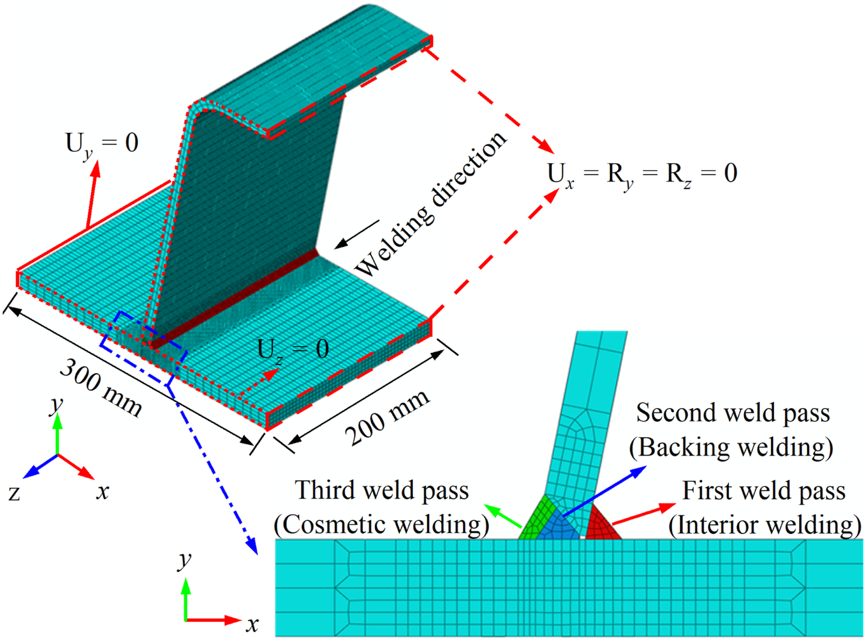
Heat source and thermal analysis
Temperature-dependent properties of the material is a key factor affecting the simulation results. In the numerical simulation of the welding process, it is difficult to obtain the temperature-dependent thermal and mechanical properties of the material used for welding numerical simulation. In this case, some scholars often use assumptions and simplified methods to deal with the temperature-dependent thermal and mechanical properties of materials in welding (Cui et al., 2019; Qiang et al., 2020; Jiang et al., 2021). In this study, the temperature-dependent properties of steel Q345qD are adopted according to the literature (Deng et al., 2008; Jiang et al., 2021), as plotted in Figure 6. Temperature-dependent properties of Q345qD: (a) thermal properties and (b) mechanical properties.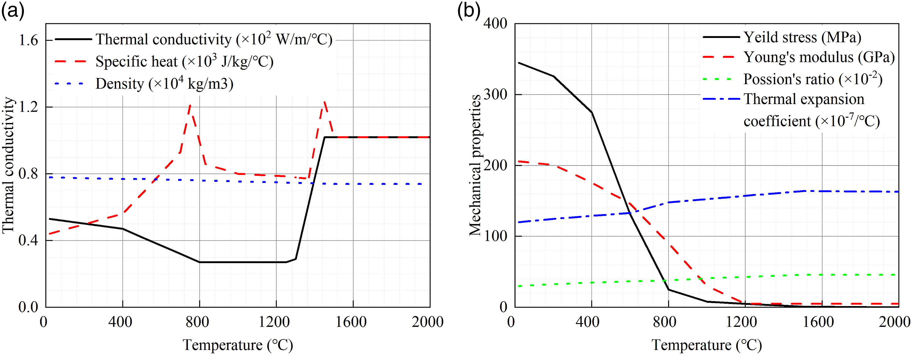
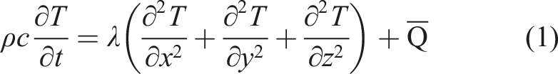
During the welding, the governing equation for thermal analysis is given by:
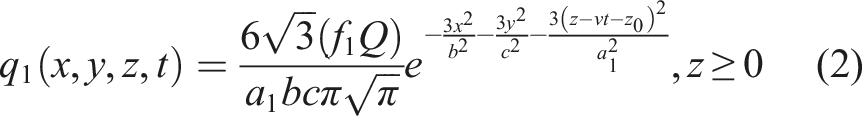
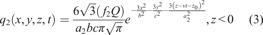
In this study, the moving heat source is simulated using the double ellipsoidal heat distribution model proposed by Goldak et al. (1984), which is expressed by the follows equations:
For the front heat source
For the rear heat source Double-ellipsoidal heat source model.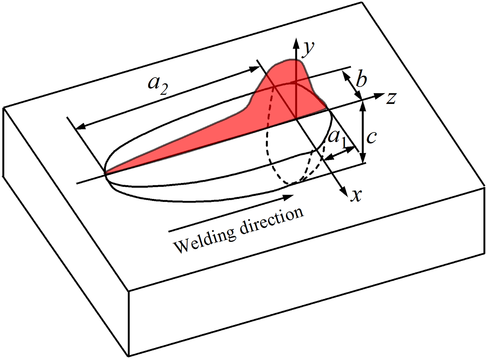
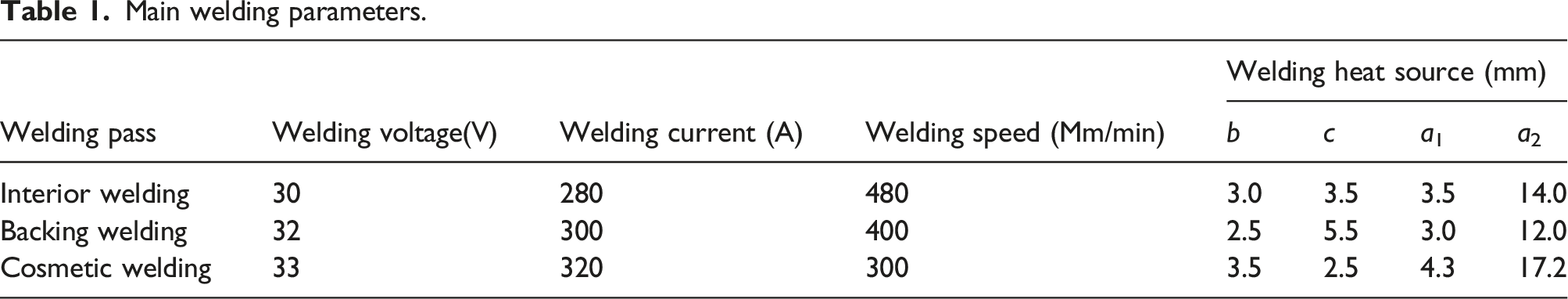
The DFLUX subroutine is compiled by FORTRAN during the welding process to implement the moving heat source loading for multi-pass welding with variations in position and time. The parameters of the welding heat source are adjusted according to the molten pool profile. The boundary of the molten pool is obtained by using the isothermal curve at the melting point of steel Q345qD (1440°C). Figure 8 compares the simulated molten pool profile with the experimental molten pool profile by Zhang et al. (2021b). The simulated molten pool profile is similar to the experimental molten pool profile. The dimensions of the simulated molten pool are about 0.75 times of the dimensions of the experimental welds. Noteworthy, the dimensions of the inner and outer welds in the simulation are 6 mm and 10 mm, respectively. While the dimensions of the inner and outer welds in the experiment are 8 mm and 13 mm, respectively. Therefore, it is feasible to simulate the heat input of the welding process. The welding parameters used in the present simulation are listed in Table 1. FEM compared to the molten pool profiles of the literature (Zhang et al., 2021b) (Units: °C). Main welding parameters.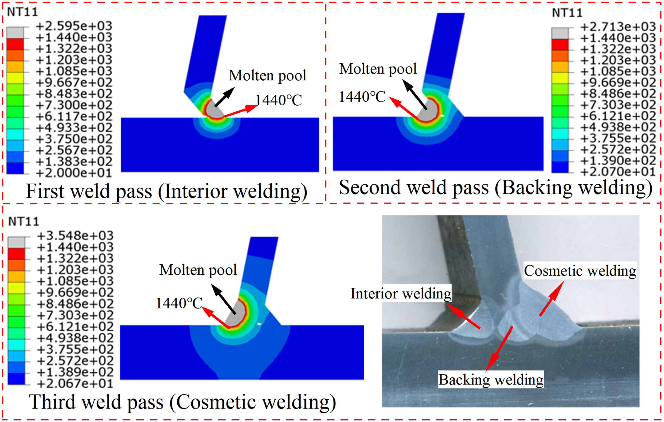
Mechanical analysis
During the welding, the material undergoes the local plastic deformation, resulting in WRS and strain. For the mild steel, the total strain can be composed of three component neglecting of the phase transition effect (Deng et al., 2008; Zhang et al., 2021b), as follows:
The elastic strain εe is obtained using the isotropic Hooke’s law with temperature-dependent Poisson’s ratio and Young’s modulus. The thermal strain εth is obtained by the thermal expansion coefficient. The plastic strain εp is obtained from the elastic-plastic constitutive equation with the following features: von-Mises yield criterion, isotropic hardening rule and temperature-dependent mechanical properties.
Experimental verification of WRS
The stress field of the RTD double-sided welded joints was simulated by mechanical analysis. The initial WRS at the RTD double-sided welded joints of OSD was measured using an ultrasonic method. Details of the experimental procedure and data can be found in literature (Cui et al., 2019). Figure 9 compares the simulation results from thermal-mechanical sequential coupling analysis and the experimental data of WRS. This indicated that the numerical simulation results were in good agreement with the experimental data. Thus, it is feasible to simulate WRS by using thermal-mechanical sequential coupling method, and the results are reasonably accurate. Comparison of measurement (Cui et al., 2019) and simulation results of the WRS.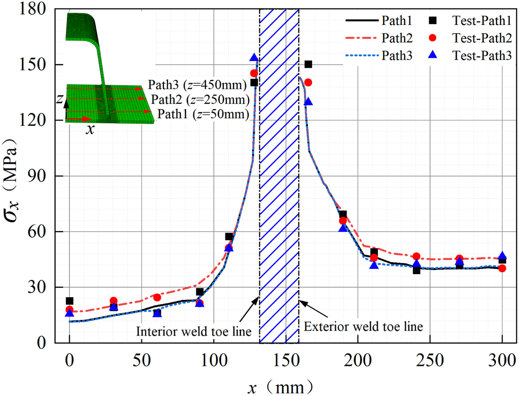
WRS analysis
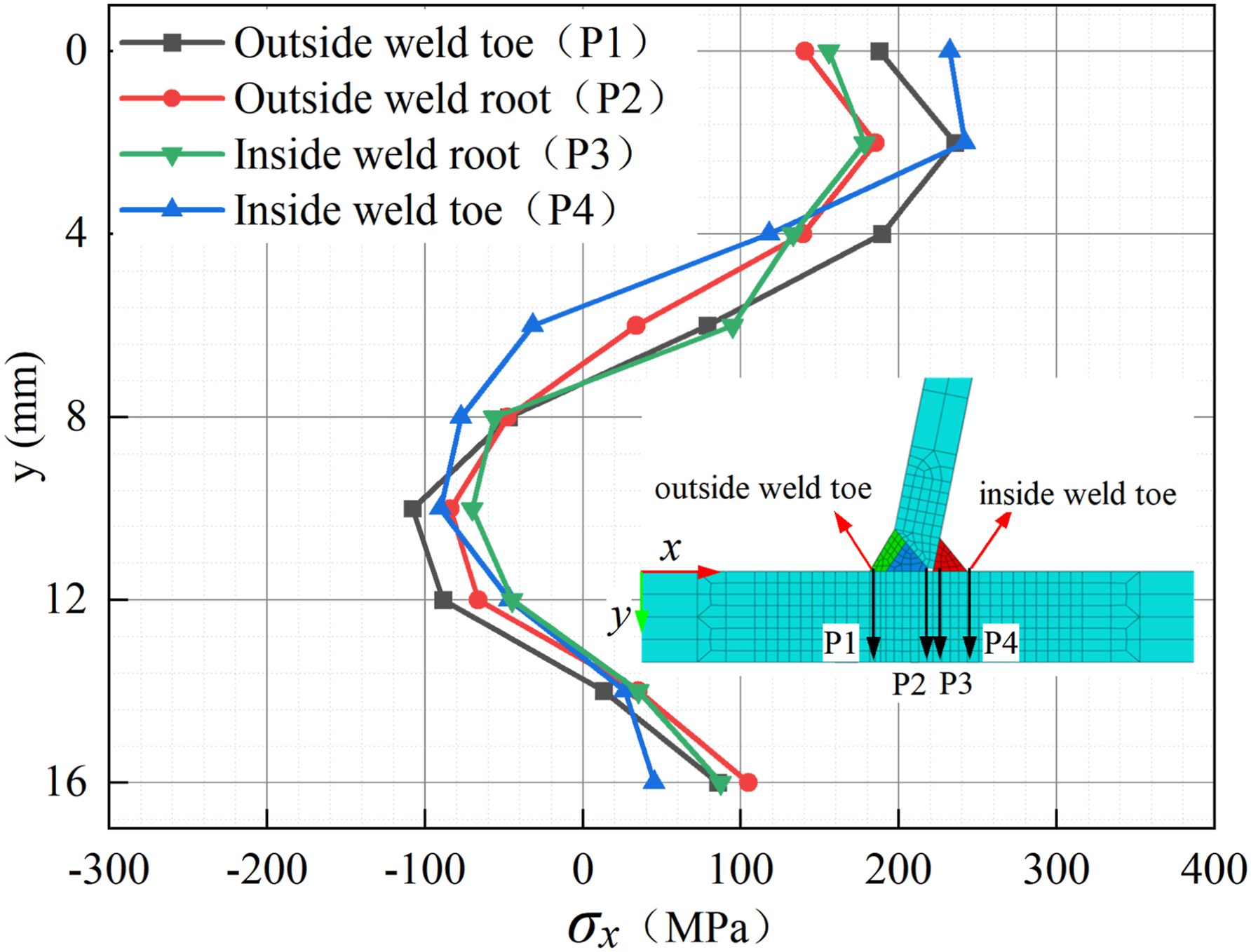
The WRS is determined by the last cooling stage of welding calculations. Figure 10 illustrates the stress distribution of RTD double-sided welded joints during the cooling stage with a stress cloud diagram. After cooling after welding, the Mises stresses of the whole weld area reaches the yield stress of the steel Q345qD (the yield stress is 345 MPa), and there is a large residual stress in the weld area. According to the crack orientation, the transverse WRS contributes a lot to crack growth. Hence, the focus of this study is placed on the transverse WRS effect on the fatigue crack growth at the crack initiation point (toe or root) and along the direction of deck thickness. The distribution of the transverse WRS along the direction of deck thickness is plotted in Figure 11. The distribution of the transverse WRS along the thickness of the deck is not uniform, presenting the state of tension-compression-tension stress distribution. Additionally, there are peaks of WRS values that differ based on various paths. The curves demonstrate a sinusoidal function pattern, indicating that the distribution of WRS for the RTD double-sided welded joints is also sinusoidal along the deck thickness direction. Mises stress distribution (Units: Pa). Distributions of WRS along deck thickness.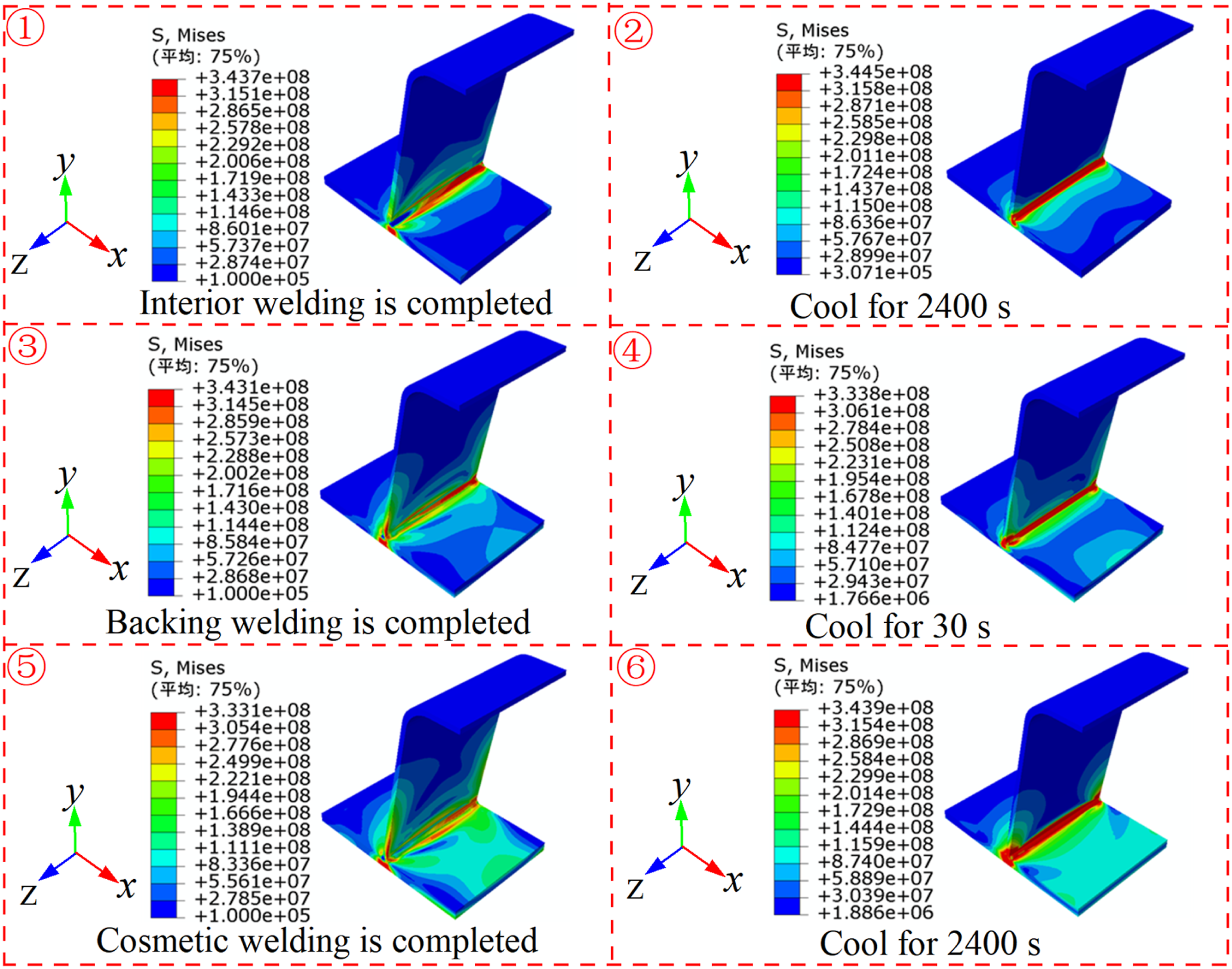
A sinusoidal function (Figure 12) can be used to fit the distribution of the WRS, which is expressed by the equation (5). Sinusoidal function.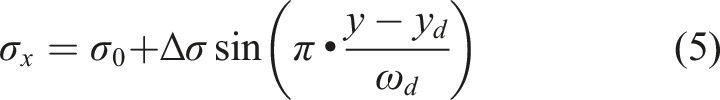
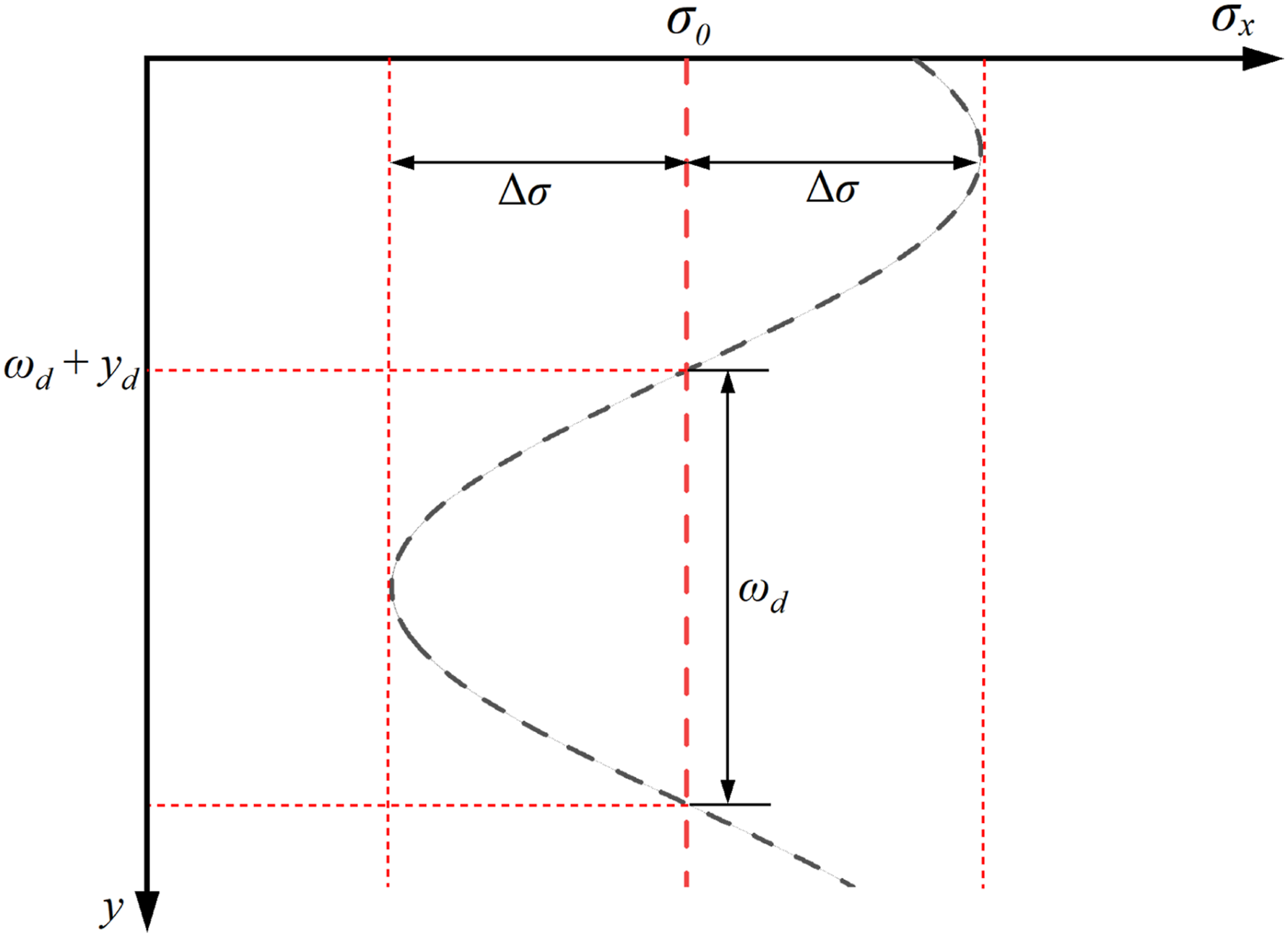
A fitting model for the distribution of WRS (σ
x
) of welding details of RTD double-sided welded joints along the deck thickness was established, as shown in Figure 13. The scatters are fitted by a sinusoidal function according to their distribution, and the coefficient of determination, R2, suggests the sinusoidal functions form a good fit to the scattered data. Fitting curves of WRS: (a) outside weld toe, (b) outside weld root, (c) inside weld root, and (d) inside weld toe.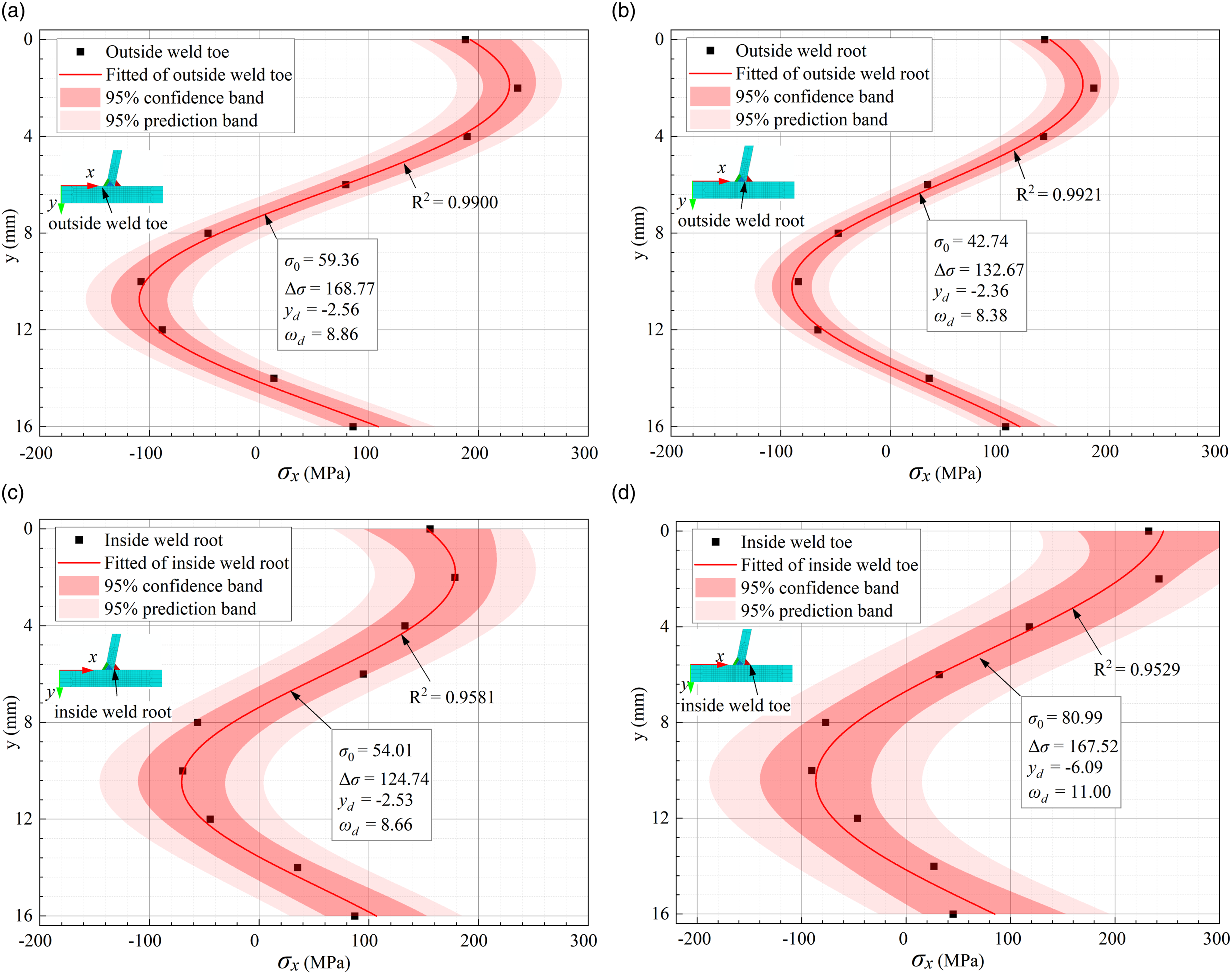
Fracture simulation
Cracked FEM
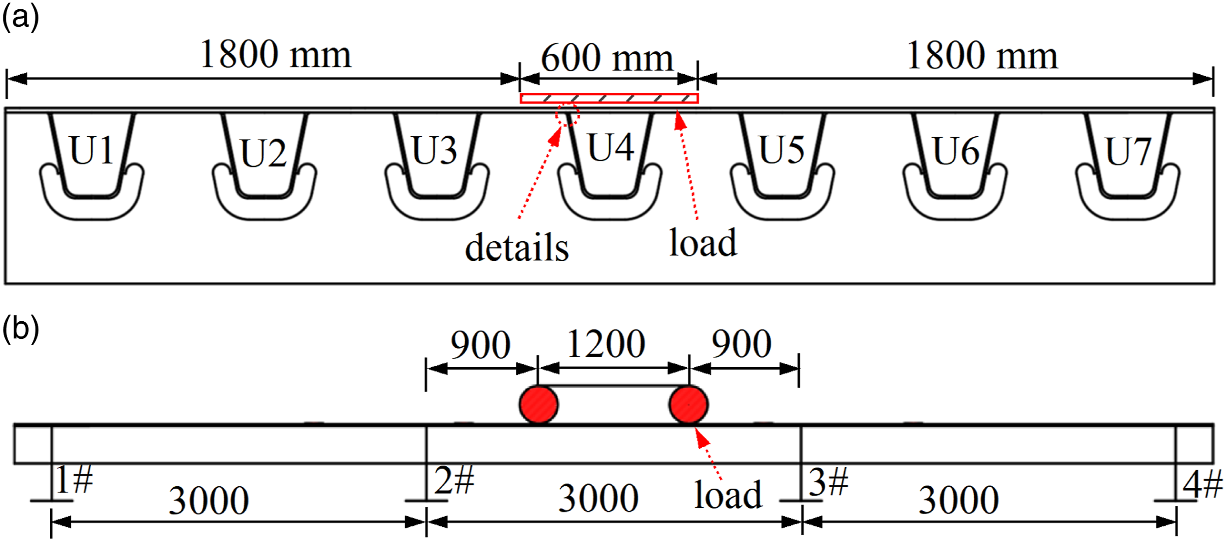
The FEM of the OSD segment with a crack was established by ABAQUS and FRANC3D software. Figure 14 shows the modeling process of the FEM, which consists of two levels: the complete model (shell-solid element) - the cracked sub-model (solid element). Firstly, a complete segment FEM without crack including shell-solid element is established by ABAQUS. The complete segmental model of OSD consists of four diaphragms and seven U-ribs. The transverse spacing of the U-rib is 600 mm, and the longitudinal spacing of the diaphragm with a thickness of 8 mm is 3000 mm. Secondly, the complete model is imported into FRANC3D and divided into local sub-model (solid element). An initial semi-elliptical surface crack with a size of a0/c0 = 0.2 mm/0.5 mm is then inserted at the weld root or weld toe of the local sub-model by FRANC3D, and re-meshed to establish a cracked sub-model. The size of the local cracked sub-model is 300 mm × 300 mm × 316 mm.
The steel Q345qD with a Young's modulus of 206 GPa and a Poisson's ratio of 0.3 were assigned to the FEM. In the complete model, the shell element is simulated by a 4-node shell element (S4R) with mesh size of 100 mm. The solid element is simulated by a 20-node solid element (C3D20R) with global mesh size of 10 mm, refined to 1 mm in the vicinity of welded joints. In the cracked sub-model, the element near the innermost circle of the crack tip is a 15-node wedge element, and the element in the outer circle is a C3D20 hexahedron element. The mesh size of the local cracked sub-model is 0.02 mm. The following boundary conditions of the complete model were preassigned in ABAQUS: (a) The vertical translation (U y = 0) and rotations (R x = R z = 0) are constrained for all nodes of the lower edge of the diaphragm to simulate the support of the diaphragm; (b) The longitudinal translation (U z = 0) and rotations (R x = R y = 0) are constrained for all nodes of two ends of model to simulate the boundary conditions at the interior U-rib and deck plate; and (c) The transverse translation (U x = 0) and rotations (R y = R z = 0) are constrained for all nodes of two sides of the model to simulate the boundary condition at the interior diaphragm and deck plate. In the complete model, the boundary between the solid element and the shell element is constrained by the shell-solid coupling in ABAQUS. The contact surfaces of the sub-model and the local cracked sub-model are connected by tie constraints.
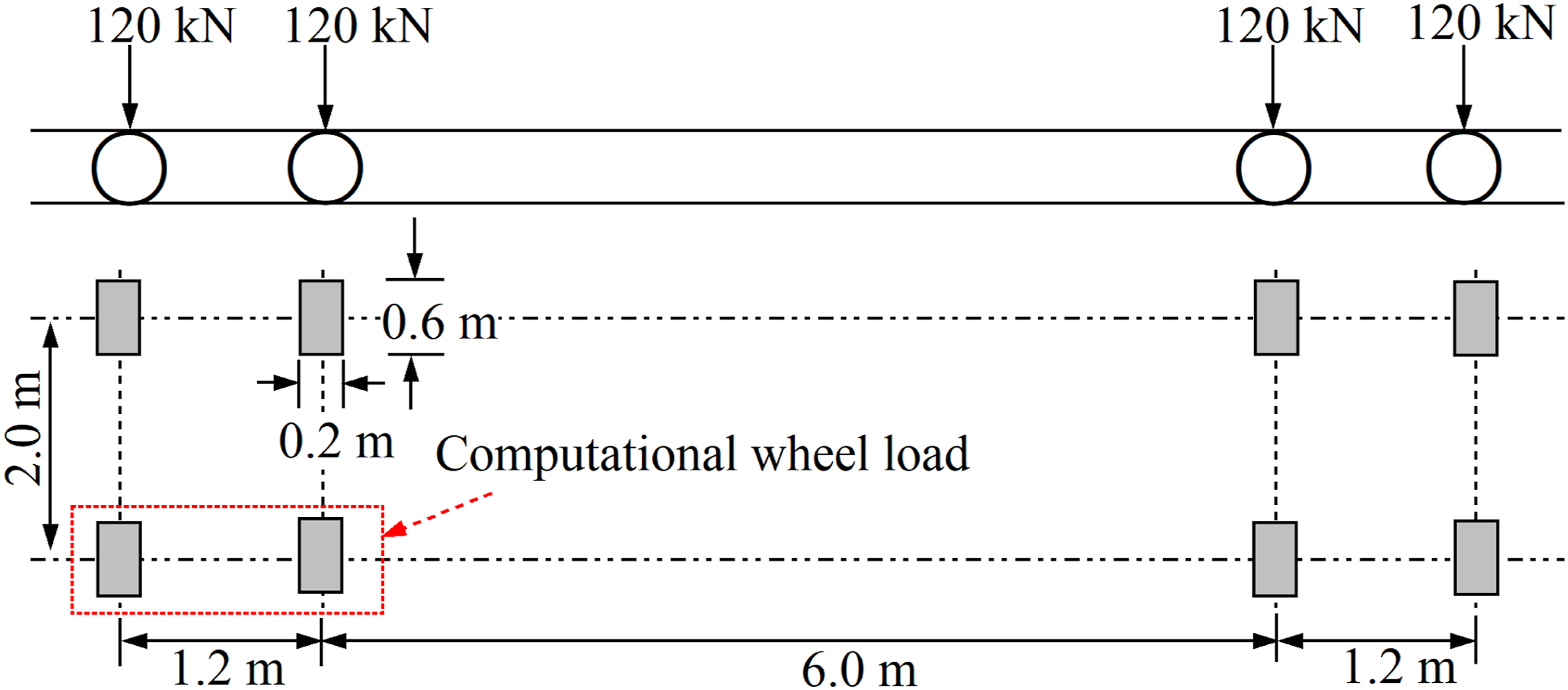
The fatigue load model III (JTG D64-2015, 2015) was used for simulation. The geometry of mode III is shown in Figure 15. The stress at the RTD double-sided welded joints of OSD was dominated by significant local effects under wheel loads. The stress generated by one side of the wheel was not superimposed on that from the other side of the wheel. In the longitudinal direction of the bridge, each axle could produce an individual stress cycle at the detail of the RTD double-sided welded joints only when the detail was underneath the deck plate covered by the wheel load distribution width (Zhu et al., 2021). Hence, the one-sided twin axle loading model with a contact surface of 600 mm × 200 mm is used in the FEM analysis of the RTD double-sided welded joints of OSD. Moreover, the heavy vehicle load is one of the leading causes of fatigue cracking of OSD (Lu et al., 2019). Thus, this study considered the influence of overloading of the vehicle, the weight of each axle of 250 kN was used to perform fatigue analysis. The load position of the vehicle load (X = 100 mm, Z = 0 mm) is shown in Figure 16. The geometry of mode III and computational fatigue load are shown in Figure 15. FEM of RTD double-sided welded joints of OSD (Unit: mm). Fatigue load mode III and computational wheel load. Loading cases (Unit: mm): (a) transversal loading condition and (b) longitudinal loading condition.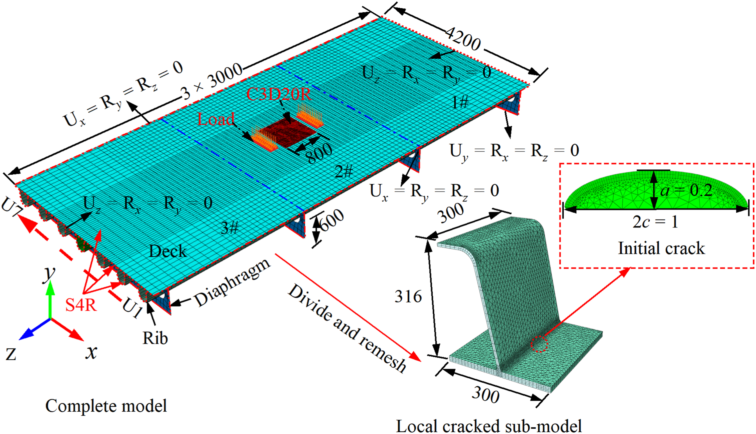
SIF analysis of crack
A numerical method using the volumetric integral known as “M-Integral” is presented for calculating the SIF of cracks in three modes. The M-Integral method was first developed by Yau et al. (1980) and has been implemented into the three-dimensional fracture mechanics software FRANC3D. Numerical examples and verification as explained in a previous paper (Liu et al., 2019).
The SIF values of cracks in RTD welded joints of OSD may be significantly influenced by the WRS, which can influence the fatigue crack growth behavior (Liu et al., 2019; Cui et al., 2019). To evaluate fatigue crack growth considering WRS, the superposition principle of LEFM is employed by Glinka (1979). The equation used to calculate the SIF of the crack under the combined action of external load and WRS is as follows:
In the present study, the distribution of WRS in the RTD double-sided welded joints is depicted in Figure 13. The equivalent SIF values, K, of the mixed mode of opening-mode (type I), sliding-mode (type II), and tearing-mode (type III) were calculated for the considered OSD by using the FEM depicted in Figure 14. The SIFs along the crack fronts of the initial fatigue crack of the four weld details of the RTD double-sided welded joints considering WRS and without considering WRS are presented in Figure 17. The SIFs along the crack fronts of the crack identified by means of a normalized coordinate. It is observed that WRS has a greater influence on the SIF at the midpoint of the crack front than at the ends of the crack front at the surface. Moreover, the SIF value considering WRS is much higher than that without considering WRS. Therefore, WRS can significantly influence the SIF values of the crack front of the RTD double-sided welded joints. Regardless of whether or not WRS is considered, the SIF value at the weld toe of the RTD double-sided welded joints is higher than at the weld root. Thus, the worst fatigue vulnerability of the RTD double-sided welded joints exists at the weld toe. In this study, only the crack growth behavior at the weld toe of RTD double-sided welded joints was studied. SIF of initial crack: (a) outside weld toe, (b) outside weld root, (c) inside weld root, and (d) inside weld toe.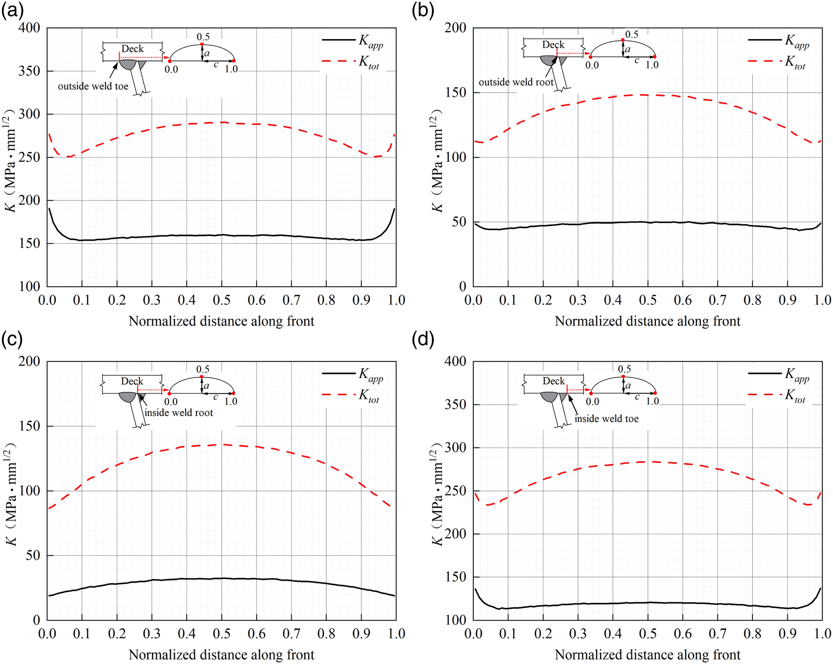
Fatigue crack growth analysis
The Paris-Erdogan law (Paris et al., 1963) is a well-known power model to predict the fatigue crack growth based on LEFM. On this basis, Elber (1971) has introduced the concept of crack closure and applied the effective SIF range (∆Keff) instead of the SIF range (∆ K) as the driving force for fatigue crack growth, known as Paris-Elber law:


In the residual stress field, under the cyclic loads, the total SIF range ∆K
tot
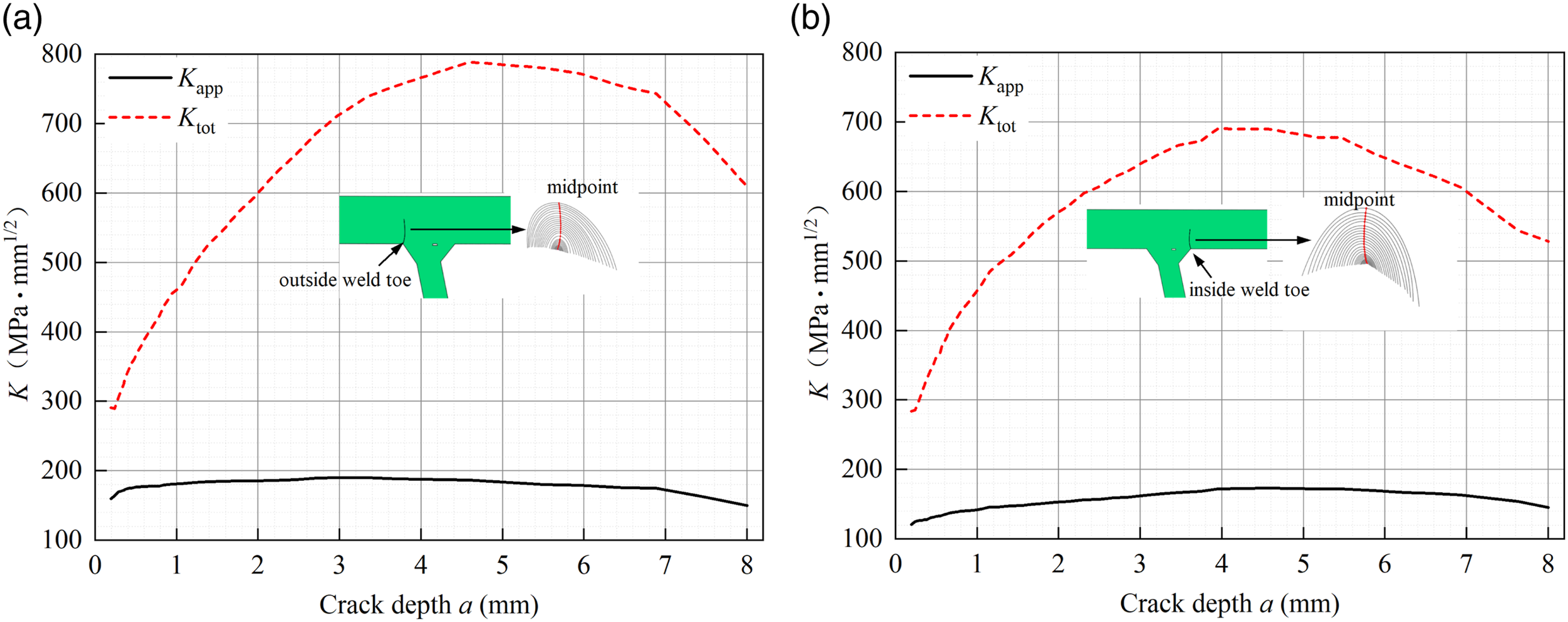
and effective SIF ratio Reff is determined based on the calculated values of Ktot,max and Ktot,min, which are given as: SIF values versus the crack depth: (a) outside weld toe and (b) inside weld toe.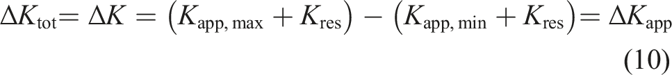
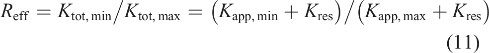
According to equation (11), the Reff values considering WRS are calculated. Figure 19 presents the Reff values versus the crack depth a. The variation of the Reff value at the outer and the inner weld toes of RTD double-sided welded joints with the crack depth is similar. The Reff values of the crack at the midpoint increase rapidly and then decrease slowly with increasing crack depth. In the region of the RTD double-sided welded joints, where positive WRS prevail, Reff values are positive, which could increase fatigue crack growth rate. Variation curves of Reff.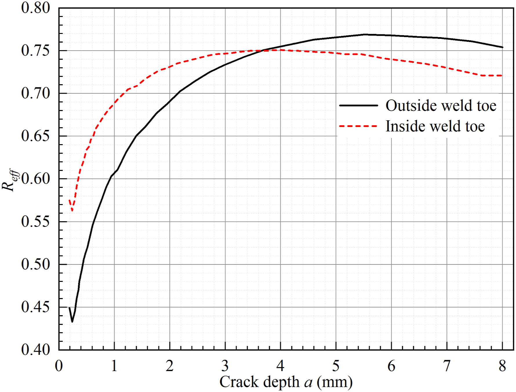
According to equation (9), the U values considering WRS are calculated. Figure 20 presents the U versus the crack depth a. The U of the fatigue crack at the outer and the inner weld toes is consistent with the change rule of the crack depth. The U value of the midpoint crack increases first and then decreases with the increase of the crack depth. Variation curves of U.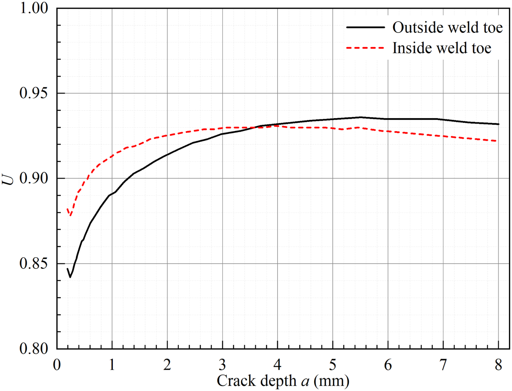
According to equation (8), the effective SIF range ∆Keff is calculated. Figure 21 presents the variation curves of the ∆Keff at the midpoint of the crack front along the growth path (0.5) of the welded toe of RTD double-sided joints at each stage of crack growth. It is observed that the variation trends of ∆Keff of the weld toe considering WRS and without considering WRS are consistent during crack growth. The ∆Keff increases gradually and then decreases gradually. The ∆Keff considering WRS are very high compared to the ∆Keff without considering WRS. Variation curves of ∆Keff: (a) outside weld toe and (b) inside weld toe.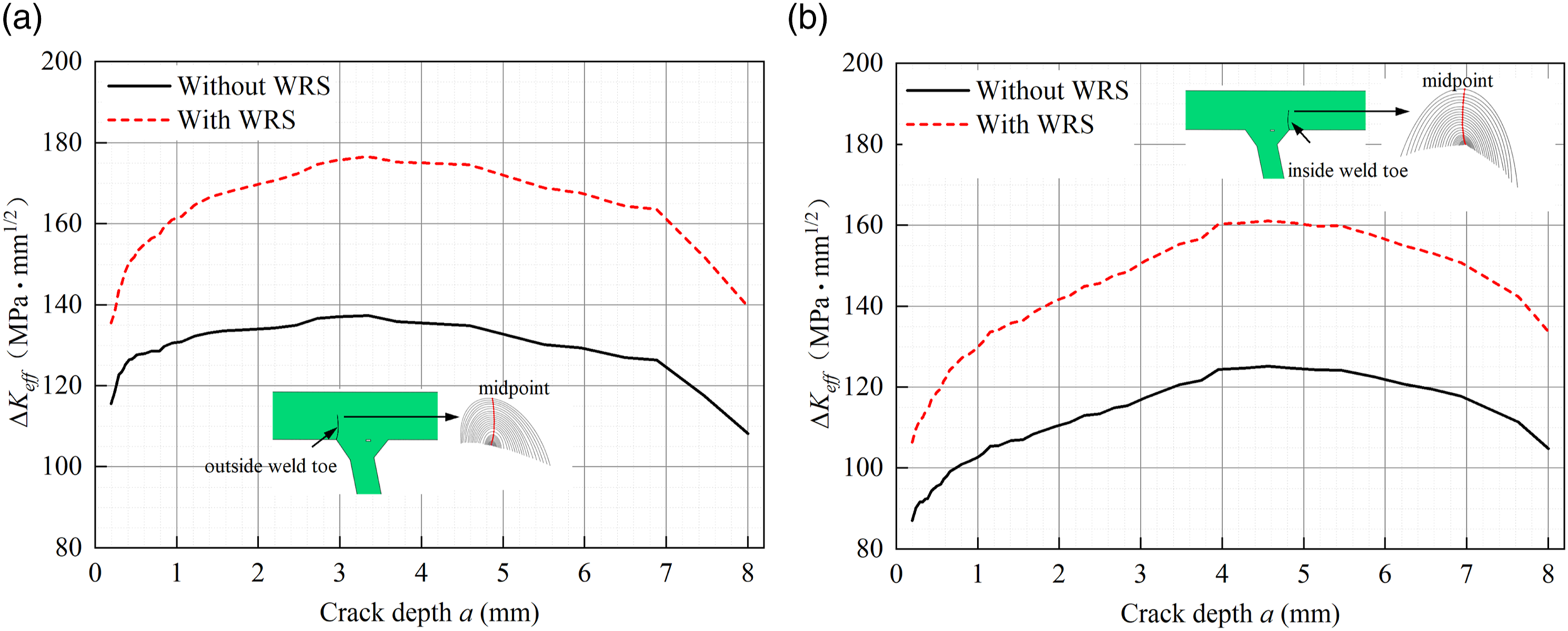
Fatigue life predictions
The residual fatigue life can be directly estimated by integrating Paris’law (Elber, 1971):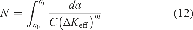
Based on the ∆Keff values and material’s constants C and m, the number of load cycles of the outside weld toe and inside weld toe of the RTD double-sided welded joints of OSD were calculated by the equation (12), as given in Figure 22. According to the IIW (Hobbacher, 2016), it is assumed that the structure fatigue failure occurs when the crack front is close to 50% of the thickness of the deck plate. From Figure 22(a), the fatigue life of the outside weld toe without considering WRS and considering WRS is 7045594 cycles and 3408849 cycles, respectively. Similarly, from Figure 22(b), the fatigue life of the inside weld toe without considering WRS and considering WRS is 10606958 cycles and 5128441 cycles, respectively. The fatigue life of the weld toe of without considering the influence of WRS is approximately twice that when considered, indicating that the existence of WRS reduces the crack closure effect and accelerates the fatigue crack growth rate of the structure. Therefore, the influence of WRS should be fully considered when designing or evaluating the fatigue life of OSD. Fatigue crack depth versus the number of cycles: (a) outside weld toe and (b) inside weld toe.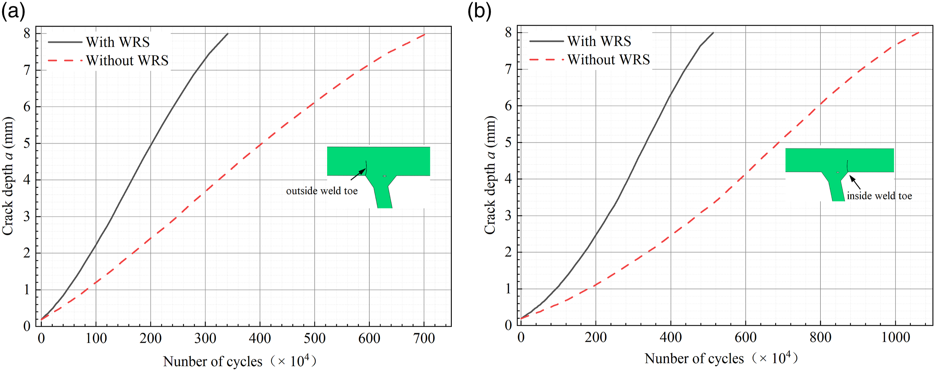
Discussion
Effect of initial crack depth on fatigue life
As discussed previously, the surface semi-elliptical crack is assumed to be the initial defect in the RTD double-sided welded joints of OSD to simulate the fatigue crack growth due to the combined action of vehicle load and WRS. To investigate the impact of initial fatigue crack with a fixed aspect ratio (a0/c0 = 0.4) on fatigue life, the geometry of the initial fatigue crack is varied in three cases as follows: Case 1 in which a0 = 0.2 mm, c0 = 0.5 mm, Case 2 in which a0 = 0.4 mm, c0 = 0.1 mm, and Case 3 in which a0 = 1.0 mm, c0 = 2.5 mm. Figure 23 shows the curves of crack depth versus the number of cycles for the three cases of the RTD double-sided welded joints of OSD. The curves demonstrate that when the initial crack aspect ratio (a0/c0) is the same, the initial crack depth has a significant effect on the fatigue life of the RTD double-sided welded joints of OSD. As depicted, the fatigue life decreases with an increase in the initial crack depth, meaning that the larger the initial crack depth, the lower the number of cycles before structural fatigue failure occurs. Fatigue Crack depth versus the number of cycles: (a) outside weld toe and (b) inside weld toe.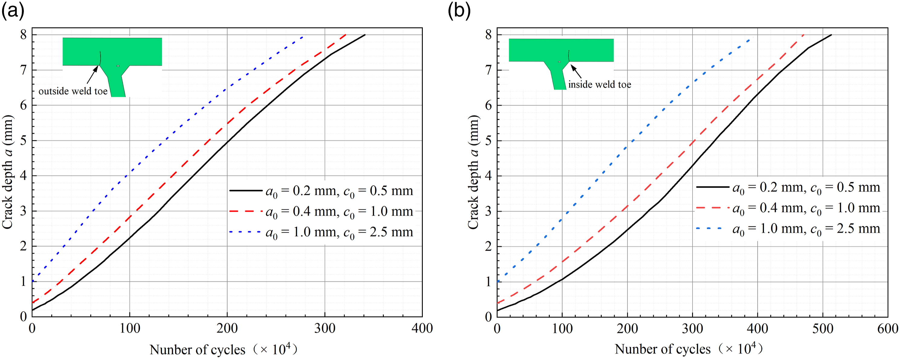
Effect of initial crack aspect ratio on fatigue life
In addition, to investigate the impact of the initial crack aspect ratio (a0/c0) on fatigue life, the initial crack depth is assumed to be a constant a0 = 0.2 mm, while crack aspect ratio is varied between 0.4 mm, 0.6 mm, and 0.8 mm. Figure 24 shows the curves of crack depth versus the number of cycles for the three cases of the RTD double-sided welded joints of OSD. The curves demonstrate that when the initial crack depth is the same, the initial crack aspect ratio has an effect on the fatigue life of the RTD double-sided welded joints of OSD. As the initial crack aspect ratio decreases, the fatigue life of OSD decreases. Fatigue Crack depth versus the number of cycles: (a) outside weld toe and (b) inside weld toe.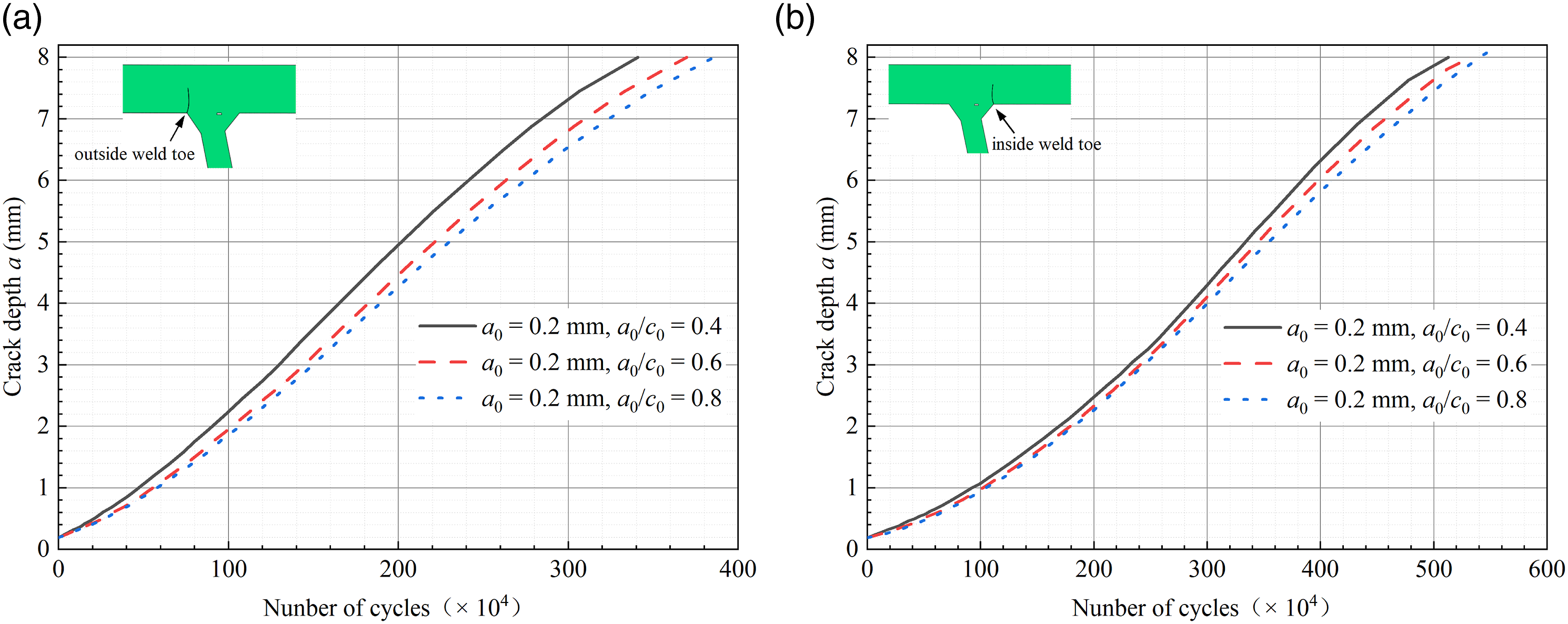
Conclusions
In this paper, the influence of the WRS on the fatigue crack behavior of RTD double-sided welded joints in OSD was investigated. Firstly, The WRS was simulated by the thermal-mechanical sequential coupling FEM to investigate the WRS distribution of the RTD double-sided welded joints. Secondly, the cracked FEM of OSD was established to investigate the influence of WRS on the fatigue crack behavior of surface cracks at the weld toe. The influence of initial crack size on fatigue life is also discussed. Based on the above investigations, the following conclusions can be drawn: (1) The WRS simulation results indicate that the distribution of transverse WRS along the deck thickness direction is tension-compression-tension stress, which has the property of a sinusoidal function. Therefore, the sinusoidal function can be used as an empirical distribution model of WRS for fatigue analysis. (2) The fatigue crack growth simulation results indicate that the variation of ∆Keff at the weld toe considering WRS and without considering WRS are consistent during crack growth. The ∆Keff value increases significantly considering WRS. It shows that the WRS will significantly increase the average stress level at the weld toe under vehicle load, thereby promoting fatigue cracking. (3) Under vehicle load, the fatigue life of the weld toe without considering WRS is approximately twice times that of considering WRS. Therefore, it is crucial to fully consider the influence of WRS when designing or evaluating the fatigue life of OSD. (4) The size of the initial crack plays a crucial role in determining the fatigue life of the outside weld toe of RTD double-sided welded joints of OSD. Specifically, when the initial crack shape ratio remains constant, the fatigue life of OSD decreases as the initial crack depth increases. Similarly, when the initial crack depth is consistent, the fatigue life of OSD decreases as the initial crack aspect ratio decreases. (5) Material parameters are important factors affecting the WRS of structures. WRS distribution of the RTD double-sided welded joints considering actual material properties is a follow-up research work.
Footnotes
Declaration of conflicting interests
The author(s) declared no potential conflicts of interest with respect to the research, authorship, and/or publication of this article.
Funding
The author(s) disclosed receipt of the following financial support for the research, authorship, and/or publication of this article: This work was supported by the Natural Science Foundation of Hunan Province (2023JJ50180, 2023JJ50188), the Scientific Research Foundation of Hunan Provincial Education Department (22C0300, 22B0567), and the Open Fund of Industry Key Laboratory of Traffic Infrastructure Security Risk Management (Changsha University of Science & Technology) (18KF04).