
Abstract
The unbonded post-tensioned precast concrete joint based on PRESSS (Precast Seismic Structural System) technology has a simple form, convenient construction, and strong deformation-recovery properties. In this paper, both experimental and theoretical analysis methods were used to study the influence of different energy dissipation components on the seismic performance of the unbonded post-tensioned precast concrete joint. First, based on the existing ‘plug-and-play’ energy dissipation device, this paper improved its construction and designed two types of joints with new external energy dissipaters and internal energy-dissipating bars, respectively. Subsequently, low-reversed cyclic loading experiments were conducted. The two joints’ seismic performance indexes, failure mode, hysteresis curve, skeleton curve, ductility coefficient, and residual deformation were compared and analyzed. The experimental results showed that internal energy-dissipating bars exhibited greater energy dissipation. In contrast, the joint with the new external energy dissipater had higher initial stiffness than the joint with internal energy-dissipating bars. In addition, the force transmission mechanism and the calculation formula of the initial rotational stiffness of the joints were deduced through theoretical analysis, and the theoretical derivation was further verified by combining the experimental values. Overall, both joints conformed to the definition of semi-rigid connections in EC3, and the joint design conformed to the “strong column and weak beam, strong joint and weak member” principle. Finally, a new anchoring system for the energy dissipaters is proposed to ensure the effective connection between the energy dissipater and the bearing.
Keywords
Introduction
With the increasing demand for green buildings and the development of environmental protection consciousness, the advantages of the precast structures, such as high production efficiency, lower labor costs, and reduced wet work on construction sites, are required to meet environmental protection and social development standards. Precast buildings featuring industrialized component production and on-site precast construction mode have been widely concerned. In the 1990s, the United States and Japan put forward the “Precast Seismic Structural System (PRESSS)” plan to start prestressed precast concrete frame research (Priestley, 1991, 1996). For such a structure, the precast components are firmly combined by unbonded prestressing tendons so that the pre-tightening force strongly connects each component, improving the overall performance of the precast structure. The unbonded prestressing tendons can remain in the elastic stage under load. The structure regains the original position where deformation does not occur with the prestressed force. The structure with prestressing tendons has many advantages, including small residual deformation, good self-centering ability, and convenient repair after an earthquake.
Many scholars have done much research on precast prestressed structures. Priestley et al. (Priestley and Tao, 1993; Priestley and MacRae, 1996; Priestley et al., 1999) investigated the unbonded prestressed precast structure and found that the prestressed precast structure had good self-centering ability and ductility with good seismic performance. That is, the cracks between beams and columns were closed under the action of prestressing tendons when the loading ended. The corresponding design principles were proposed. Nakaki et al., 1999 carried out in-depth theoretical analysis and experimental research on hybrid connection frame joints and suggested that the mild steel is to be ensured with enough energy dissipation capacity. Cheok et al., 1998 studied the seismic behavior of prestressed precast joints with energy-dissipating bars, showing that these joints’ displacement angle and failure mode were similar to cast-in-place joints. Ozden and Ertas, 2007 carried out quasi-static tests of four unbonded post-tensioned prestressed precast joints and one cast-in-place joint to analyze the contribution ratio of mild steel reinforcements to the bearing capacity, where the prestressing tendons were arranged in the middle of the beam, and the mild steel reinforcements were arranged in the upper and lower parts of the beam. With the mild steel reinforcement ratio increase, the energy dissipation capacity of the joints was closer to the cast-in-place joint. Thus, the prestressed precast concrete frame is a structure with good seismic capacity, and reliable energy dissipation design is the key to ensuring its energy dissipation connection.
Some scholars have proposed employing energy dissipation devices in precast prestressed structures to ensure their energy consumption capacity. Morgen and Kurama, 2007 studied unbonded prestressed concrete frame structures with friction dampers, and found that under the influence of prestressing and dampers, the structure had good self-centering ability and energy dissipation ability. Rodgers et al., 2012a, 2012b carried out a quasi-static test and finite element simulation on precast prestressed frame joints with high-force-to-volume dampers. The results showed that the joints with high-force-to-volume damper had higher energy dissipation capacity and smaller residual deformation. Song et al., 2015 proposed a web friction-type self-centering prestressed concrete frame structure, where the unbonded prestressing tendons were arranged on the upper and lower sides of the beam, and brass plates were used to increase energy dissipation in the web at the beam end. The results showed that the pre-tightening force of the friction bolt greatly influenced the energy dissipation capacity of the structure, and the comprehensive seismic performance of the structure was good, and higher than the cast-in-place joint.
The PRESSS project proposed and applied the “plug-and-play” dissipater (Pampanin et al., 2010) in the hybrid connection seismic frame system, to achieve interchangeability of energy dissipaters. It is mainly composed of the energy-dissipating steel bar, outer steel tube and filler. Normally, it can be used in precast prestressed frame beam-column joints. And it is remarkable that this kind of external dissipater can be disassembled and replaced in time after the earthquake (Pampanin, 2012). The dissipater used the “damage concentration” principle applied to the parts with large structural deformation, effectively achieving low damage to the structure and ensuring the energy dissipation capacity of the structure. Marriott et al., 2009; Sarti et al., 2016 performed experimental research on piers with internal energy-dissipating bars and external dissipaters, and the corresponding cast-in-place structures. The results showed that the structure with external dissipater reduced the internal damage of the structure, and had better stability and energy dissipation capacity. Liu, 2019 performed material improvement and local optimization design based on the “plug-and-play” dissipater, proposing a replaceable mild steel energy dissipater. In cyclic tensile and compressive tests, the replaceable mild steel energy dissipater showed good energy dissipation capacity. Therefore, the replaceable mild steel energy dissipating apparatus has good energy dissipation capability and achieves post-earthquake repair of the structure by replacing internal energy dissipating steel reinforcement. However, verification of these new external replaceable mild steel energy dissipaters is required to examine their effectiveness in the energy consumption process of hybrid connection frame joints.
Previous studies have proved that the external energy dissipator is helpful to achieve the design goals of improving the energy dissipation capacity and replacing them after the earthquake. However, some aspects of the external energy dissipator still need to be further studied to promote the design theory, such as structural design, connection form, mechanical mechanism and contribution degree of the energy dissipation capacity. Therefore, in this paper, both experimental and theoretical analysis methods were used to study the influence of different energy dissipation components on the seismic performance of the unbonded post-tensioned precast concrete joint. Firstly, based on the existing research on energy dissipator joints, the energy dissipator was improved, and then low-cycle reverse cycle loading experiments were carried out to compare the joints failure mode and seismic performance index. Subsequently, the rotational stiffness of the two joints was analyzed by combining the test results and theoretical derivation. Finally, given the used energy dissipater installation device’s insufficient anchorage capacity, a new anchoring system for energy dissipater installation is proposed.
Experiment program
Specimen design
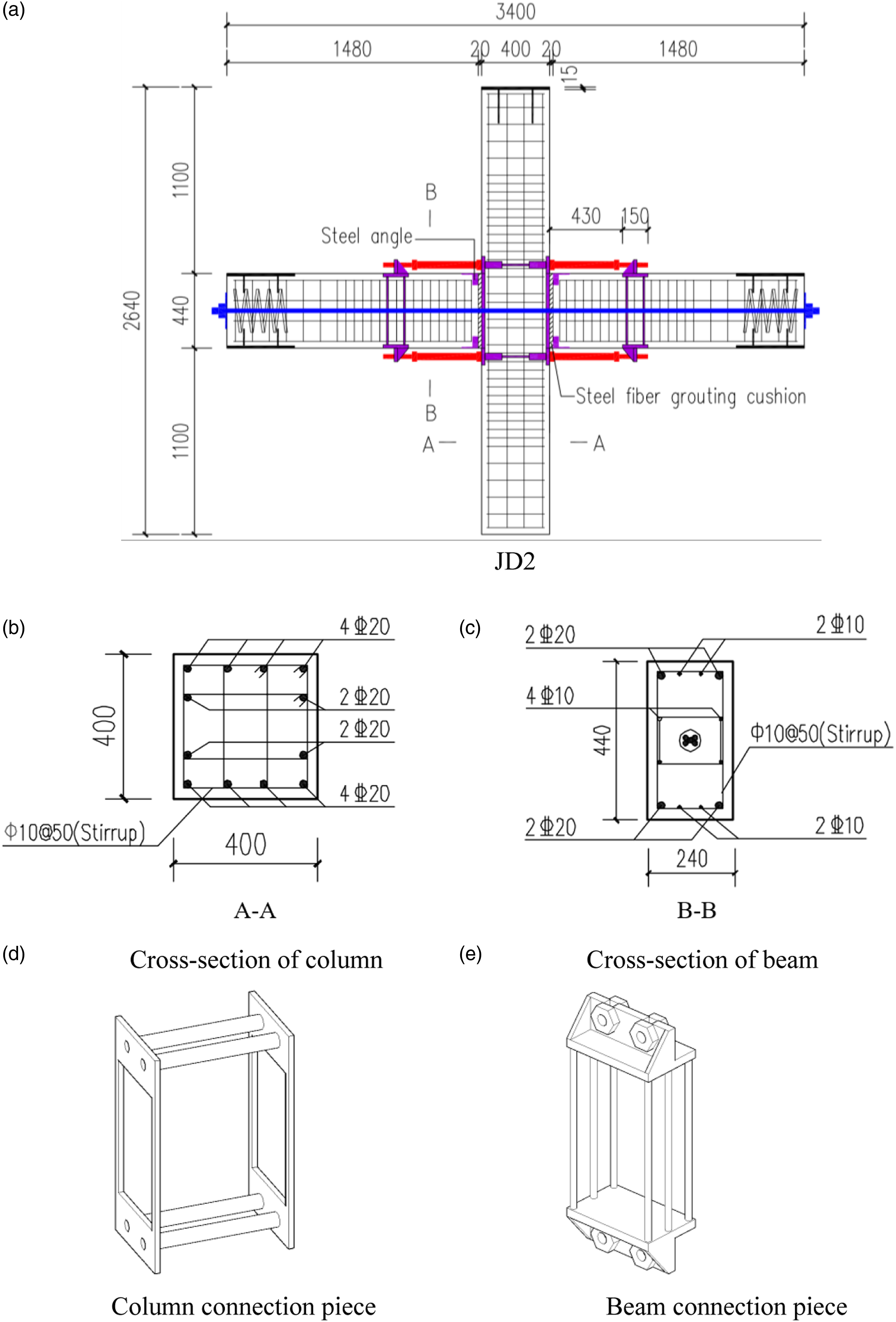
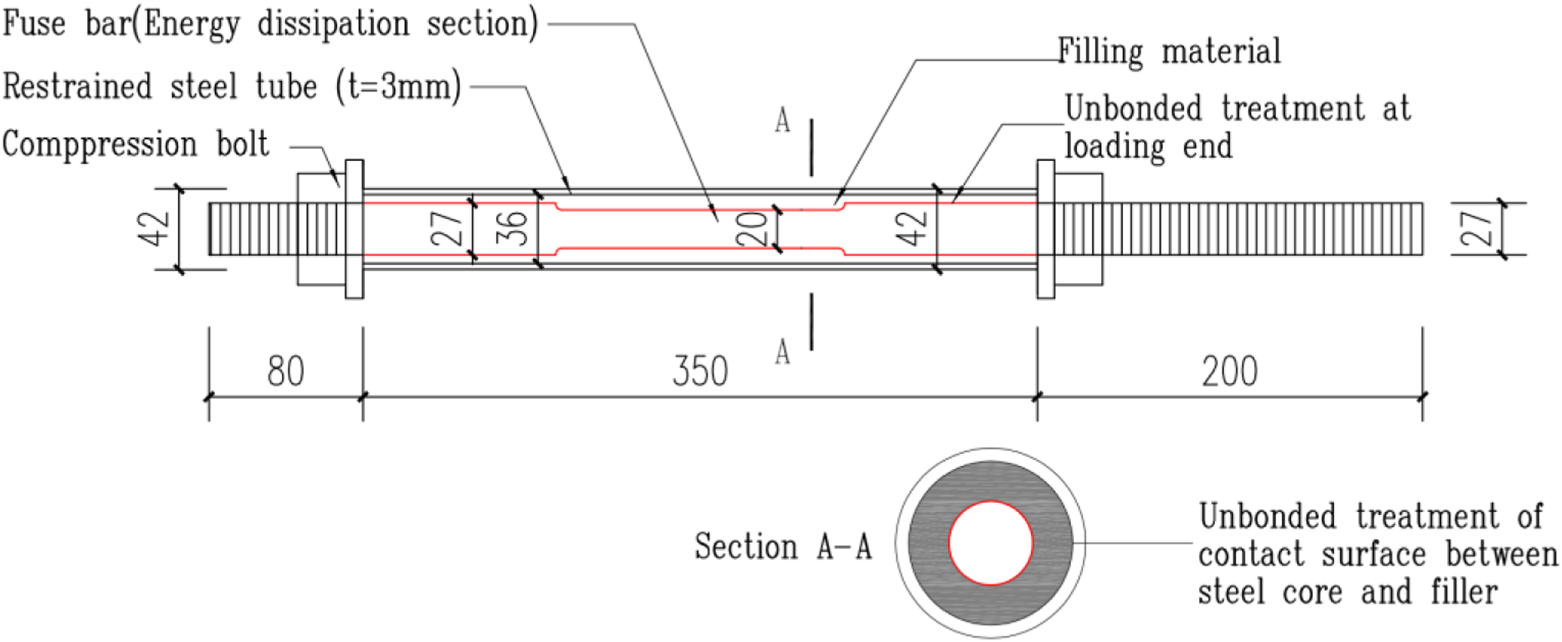
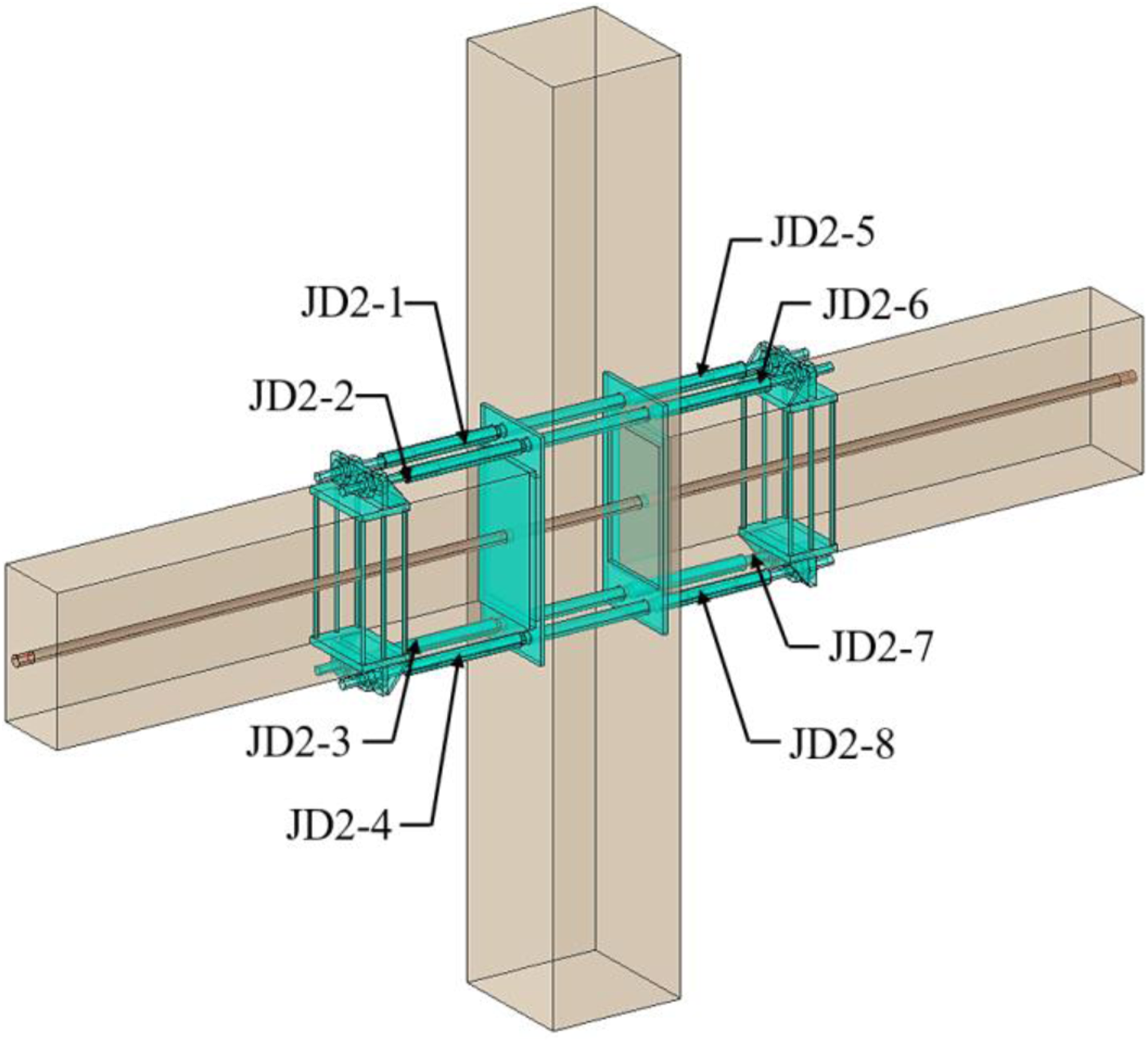
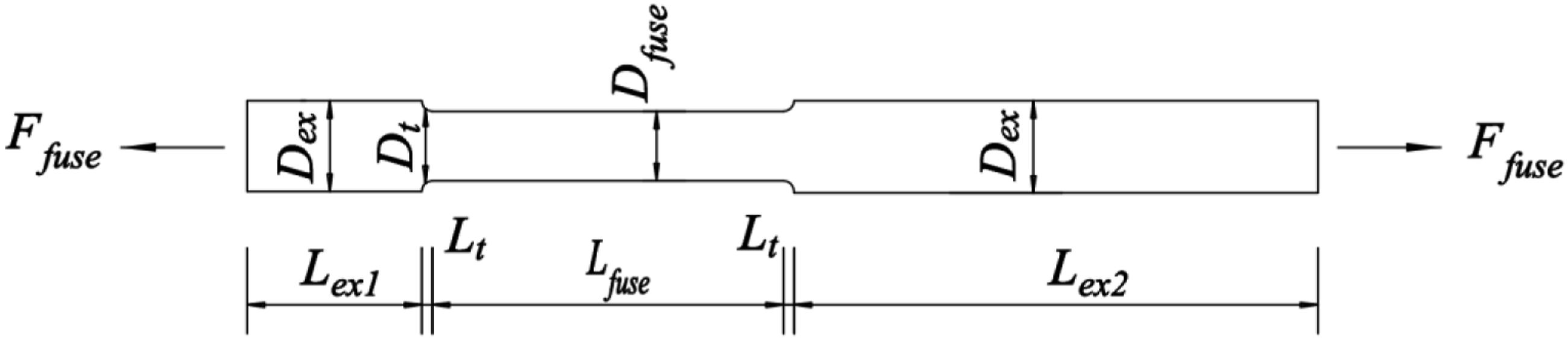
The dimensions of two precast prestressed concrete frame joints with different energy dissipation designs were the same. The beam section size was 440 mm × 240 mm, and the column section size was 400 mm × 400 mm. The precast beam and column were spliced by unbonded post-tensioned prestressed steel bars. The steel angel was set at the corner end of the joint between beam and grout pad to protect the end concrete and reduce concrete damage. Besides, the steel fiber cushions for buffering were set at the intersection of prefabricated beam and column. The difference between the energy dissipation designs of the two joints is that internal energy-dissipating bars were utilized in internal energy-dissipating bars (here in after referred to as JD1), while external dissipaters were utilized in the joint with external dissipater (here in after referred to as JD2). As shown in Figure 1, for the JD1, the energy-dissipating bars were set on the upper and lower parts of the precast beam and passed through the precast column to improve its energy dissipation capacity. As shown in Figure 2, for the JD2, the energy-dissipating bars inside the joint were removed, and external dissipaters were added on the upper and lower sides of the beams. As shown in Figure 3, the external energy dissipater was composed of the fuse bar and an external restraint system (filling material and restrained steel tube). A weakened section, 20 mm in diameter and 150 mm in width, was set as the energy dissipation part in the middle of the fuse bar. The diameters of the restrained steel tube and the end of the fuse bar were 42 mm and 27 mm, respectively. The gap between the restrained steel tube and the fuse bar was filled with filling material. Moreover, the filling material and the energy dissipation section were not bonded, and the threads are set at the end of the energy dissipater to strengthen the connection with the joint, as shown in Figure 3. During the assembly process of the joint with internal energy dissipation steel bar, the energy dissipation steel bars were firstly embedded in the concrete column to form prefabricated concrete column. Meanwhile, the prefabricated concrete beam was made by reserving the sleeves inside before pouring the concrete beam. Finally, the energy dissipation steel bars were inserted into the reserved sleeves and grouted, and the prestressed bars were tensioned to complete the self-centering prestressed concrete beam-column joint. Structure and reinforcement drawings of JD1 (unit: mm). (a) JD1. (b) Cross-section of column. (c) Cross-section of beam. Structure and reinforcement drawings of JD2 (unit: mm). (a) JD2. (b) Cross-section of column. (c) Cross-section of beam. (d) Column connection piece (e) Beam connection piece. External dissipaters diagram (unit: mm).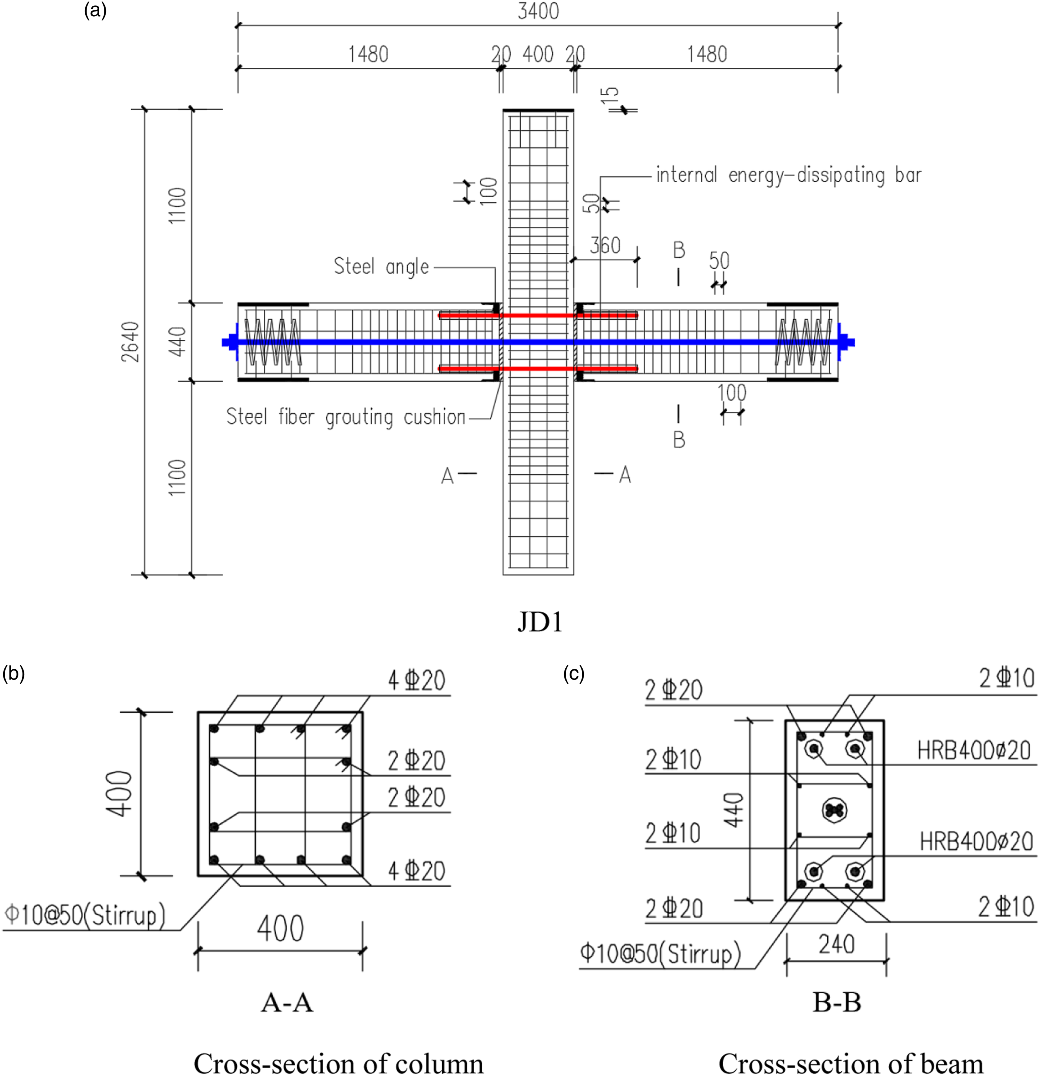
Material properties
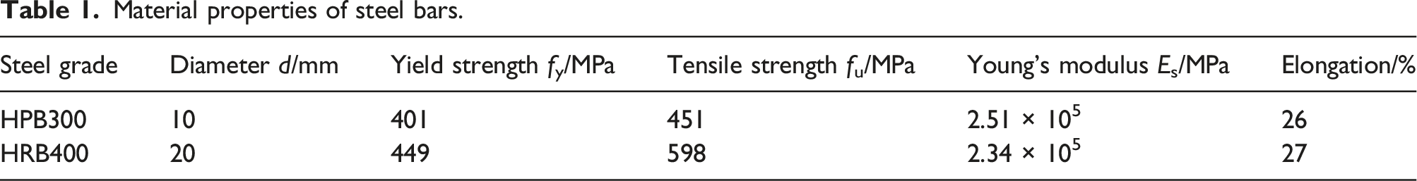
Material properties of steel bars.
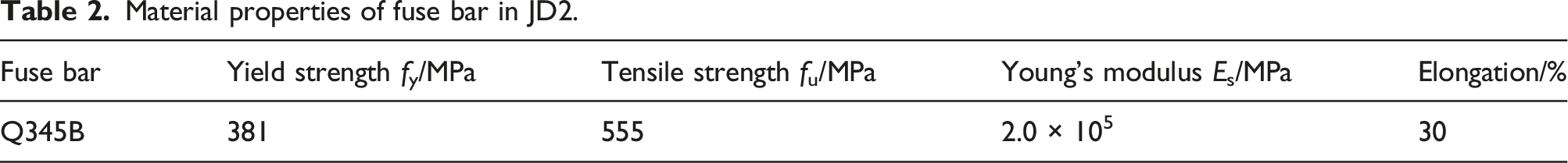
Material properties of fuse bar in JD2.
Loading system
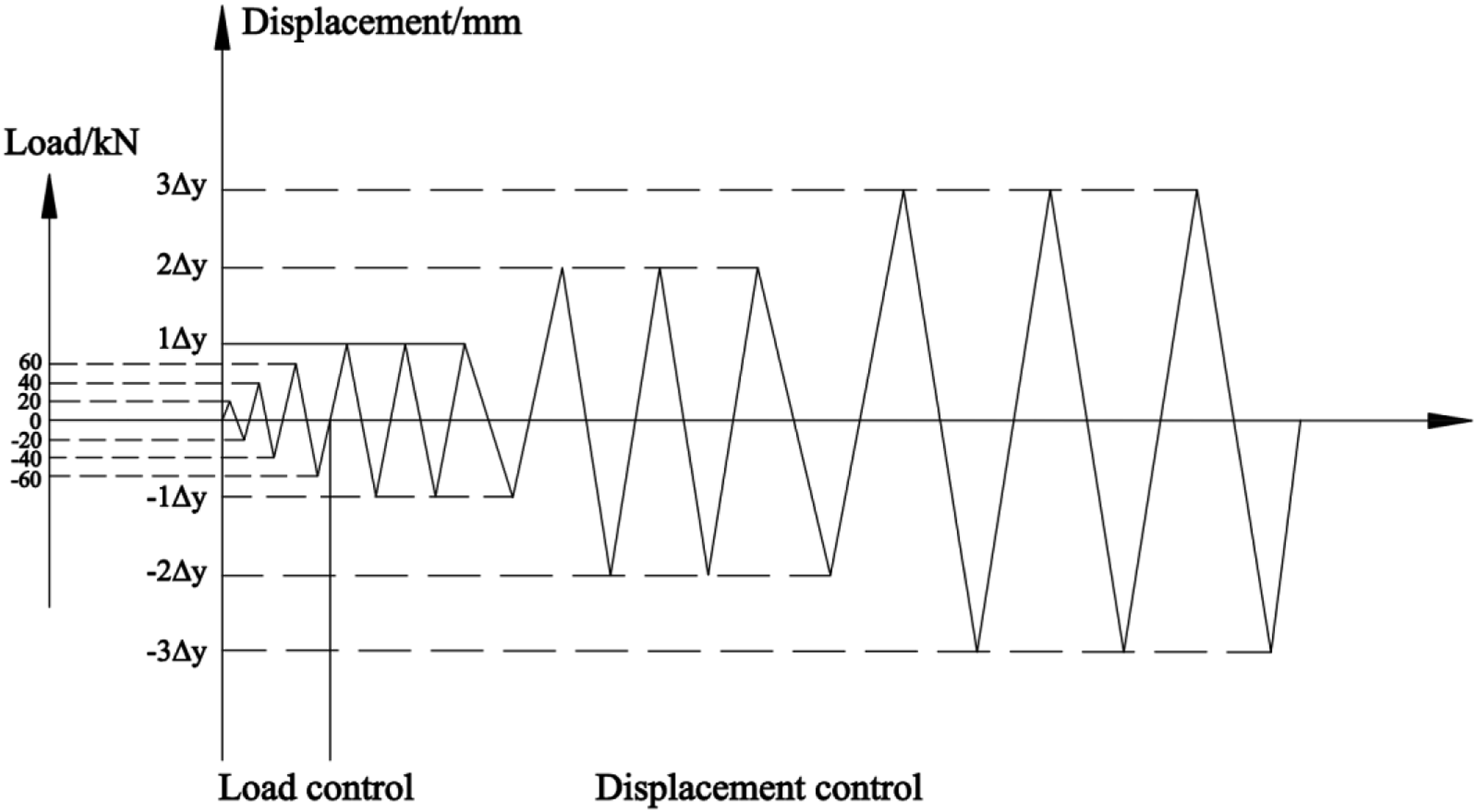
To simulate the stress situation of the beam end under earthquake, the antisymmetric low-reversed cyclic was applied to the left and right beam-ends according to “Specification of testing methods for earthquake resistant building” (JGJ/T 101-2015, 2015). The test setup is shown in Figure 4. Axial pressure is applied to the column with an axial compression ratio of 0.4, and the applied axial force on the column is kept constant. A loading system combining load-controlled and displacement-controlled modes was adopted, as shown in Figure 5. Before entering the loading yield stage, the load-controlled mode was applied. After entering the loading yield stage, the displacement-controlled mode was applied. The load was increased sequentially according to the multiples of yield displacement Δy, and the loading cycle of each stage was performed three times. When the bearing capacity of the specimens dropped to 85% of the maximum bearing capacity, the loading was terminated. Test setup. Loading system.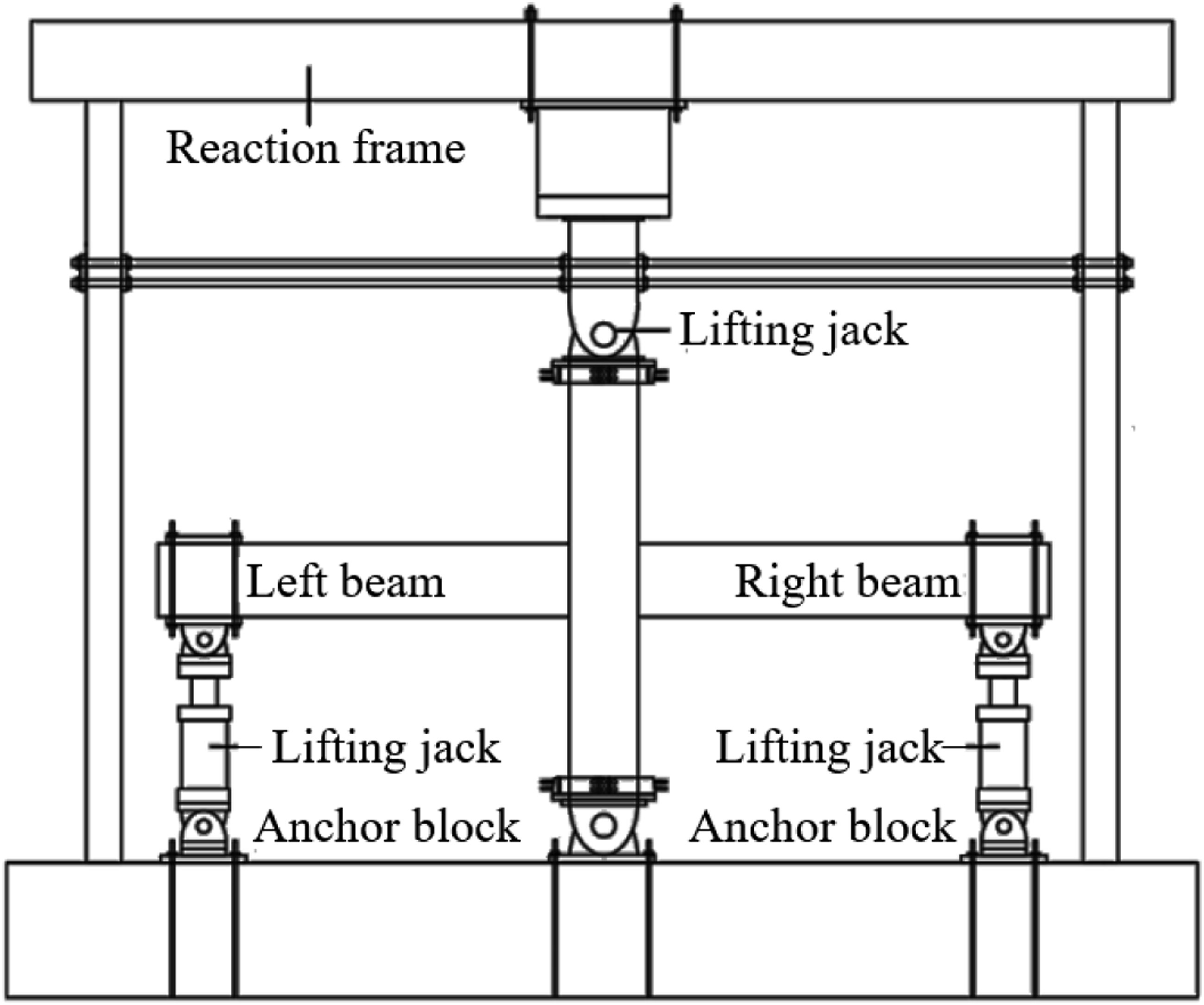
Measurement arrangement
To measure the displacement and strain of the critical part of the joint specimen during the test, a measuring scheme was designed for the displacements of the joint core area, displacements of beam end, and strains of energy dissipaters. The detailed displacement-meters and the strain gauges layouts of external dissipaters are shown in Figures 6 and 7, respectively. Displacement-meters layout. Strain gauges layout of external dissipaters.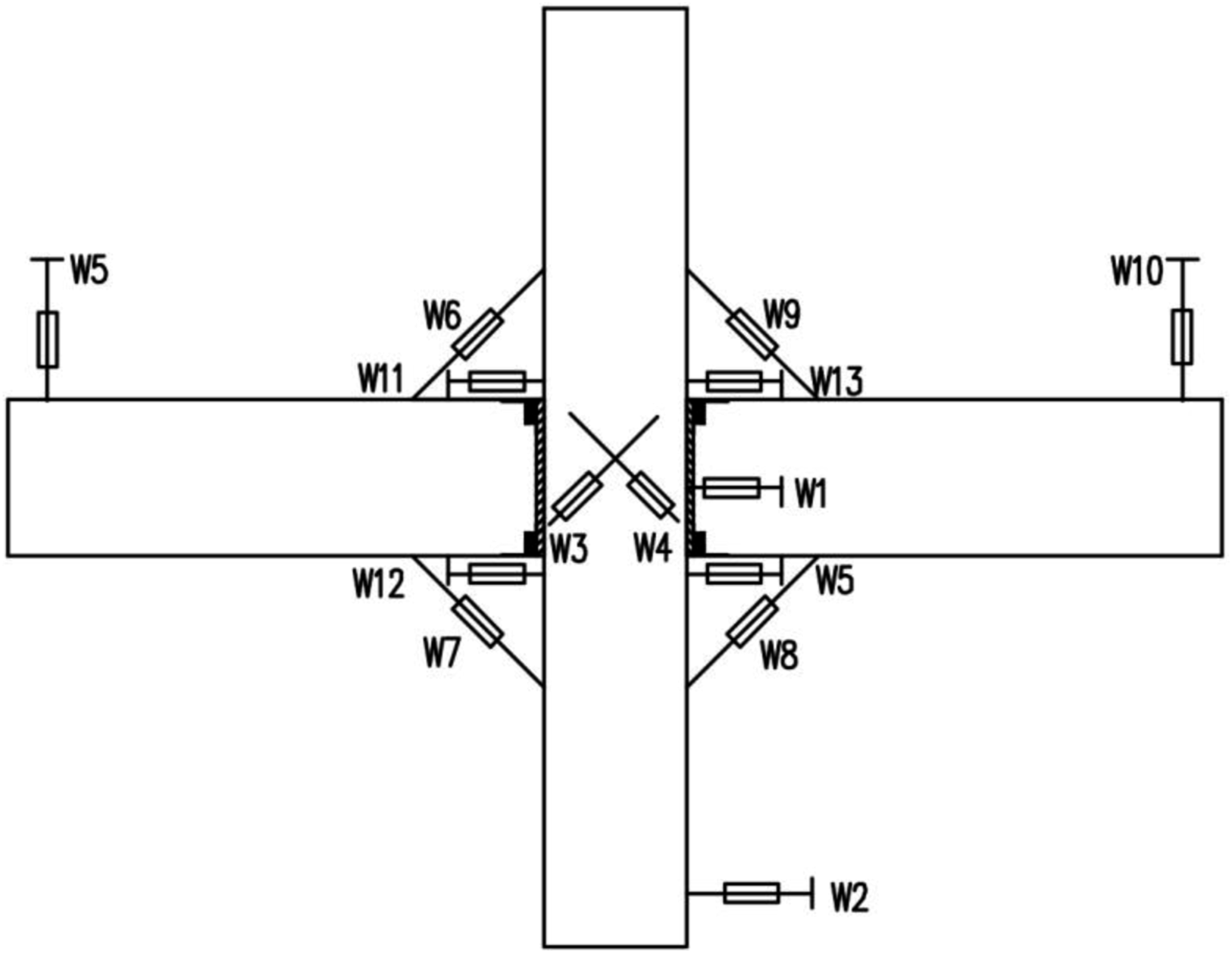
Experimental results
Failure mode
For JD1, in the loaded-controlled stage, when loaded to 60 kN, the cracks appeared on the concrete surface, and were evident at the junction of the beam and column. When loaded to 120 kN, the inflection point visibly appeared in the load-displacement curve; by this time, the specimen yielded a yield displacement Δy of 10 mm. In the displacement-controlled stage, the width of the cracks at the beam and column junction increased with the load. Moreover, the other cracks mainly extended outward from the beam and column interface. The concrete at the beam end junction was seriously damaged. Finally, when loaded to 6Δy, the loading was terminated, the concrete at the joint’s compression zone was crushed. Figure 8(a) shows the final failure of the joint. The failure mode of the joints. (a) JD1. (b) JD2.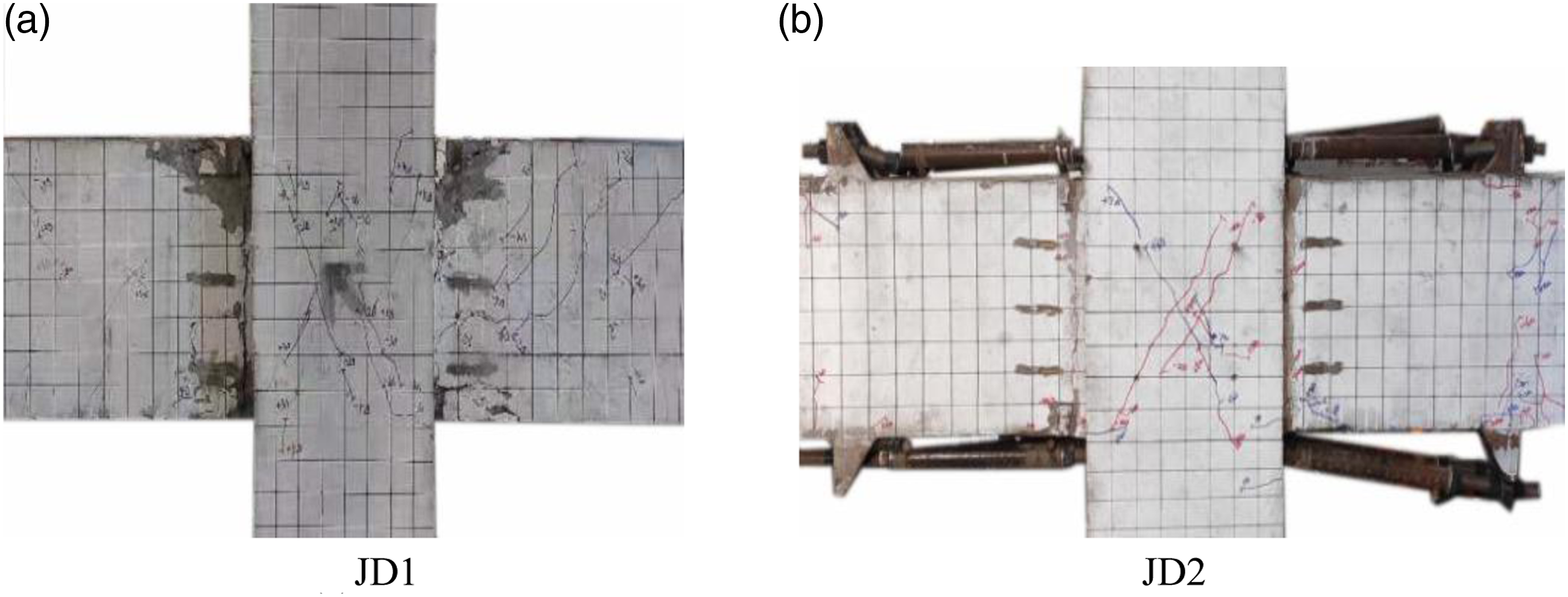
For JD2, in the load-controlled stage, when loaded to 100 kN, the tiny cracks began to appear on the concrete surface. When loaded to 110 kN, an obvious inflection point visibly appeared in the load-displacement curve; by this time, the specimen yielded, and the yield displacement Δy was 6 mm. In the displacement-controlled stage, except for the main tiny cracks at the junction of the beam and column, the other cracks were mainly located near the bearing and the dissipaters junction. The external dissipaters design reduced the concrete damage at the beam and column junction. Compared with JD1, there is no obvious concrete damage at the beam end. When the displacement-controlled load reached +7Δy, the dissipater under the left beam fell off from the bearing. When the displacement-controlled load reached −7Δy, two dissipaters under the right beam fell off the bearing. From the 8Δy second cycle, the threads at the end of most remaining dissipaters were broken, causing a significant decrease in the bearing capacity of the joint, indicating that the external dissipaters participated in the energy dissipation process of the joint to a large extent. The final failure of the joint is shown in Figure 8(b).
References (Wang et al., 2018, 2019a, 2019b) have studied precast prestressed beam-column joints with different external energy dissipaters, but the specific design and installation positions of dissipaters are slightly different from those in this paper. It can be concluded that most external energy dissipaters showed buckling deformation and the energy was dissipated through their plastic deformation in all those experimental studies. The JD2 in this paper also showed similar characteristics in the early stage of the energy-dissipater entering plastic deformation. Unfortunately, in the later loading stage, the external energy dissipaters were in a complex stress state due to the combined effect of axial force and vertical shear. Due to the insufficient anchoring capacity of the energy-dissipater installation device, some external dissipaters fell off in advance and quitted work, the energy dissipation capacity of the joint was affected in the later loading stage. When the load displacement reached 42 mm, the lower energy dissipators of the left beam separated from the bearing; when the load displacement reached −42 mm, the two lower energy dissipators on the right beam were detached from the bearing. When the load displacement reached −48 mm, the threaded segments of the energy dissipators were pulled off. Due to the premature destruction of the energy dissipators, only the undestroyed energy dissipators and the prestress maintained the connection between the beam and the column. Under the redistribution of the sectional forces, the undestroyed energy dissipator bore greater force, the destruction process of which was accelerated, affecting the structural resilience. Therefore, it is necessary to improve the anchoring capacity of the external energy dissipator bearing. However, the steel fiber grouting cushion and the angle steel at the beam end played a very good protecting role. There was almost no obvious crack at the beam end, and only a few vertical cracks appeared around the energy dissipater installation device, which provided a good foundation for the replacement of the energy dissipater after the earthquake. The experimental phenomenon is similar to that of the joints tests in the reference (Wang et al., 2019a). While in the references (Wang et al., 2018, 2019b), the steel jacket was set to prevent beam end concrete cracks. However, many beam concrete cracks were found at the adjacent areas of the steel jacket, which shows that the stiffness matching criterion between the steel jacket and the beam is worthy of further study.
In general, the JD1 has significant concrete damage at the beam-end junction after the test, and the energy-dissipating steel bars cannot be replaced, which is not conducive to structural repair after the earthquake. While setting an external energy dissipater is an effective way to achieve the post-earthquake repair. Based on the external energy dissipater proposed in this paper, the bearing needs to be improved to fix the energy dissipaters effectively, and the ratio of the energy dissipation section diameter to the loading end diameter also needs to be further optimized to ensure normal operation of the energy dissipaters. Therefore, further experiments should investigate how to utilize the energy dissipation performance of the dissipater from the construction level of the beam-column connection in conjunction with factual scenarios.
Hysteretic curves
The hysteretic curves of JD1 and JD2 shown in Figure 9 demonstrate that the two joints were in the elastic stage at the initial loading stage, and the area of the hysteresis loop was small. After entering the yield stage, the two joints entered the displacement-controlled stage, presenting plastic properties, and the hysteresis curves gradually became full. At the end of the loading process, the concrete at the column and the beam end junction of JD1 was seriously damaged, the threads at the end of JD2 dissipaters were broken, and the bearing capacity of the two joints decreased. The residual deformation increased slightly with the load, but the value was small. Both joints performed good self-centering ability. Hysteretic curves of JD1 and JD2. (a) Left beam of JD1. (b) Right beam of JD1. (c) Left beam of JD2. (d) Right beam of JD2. Skeleton curves.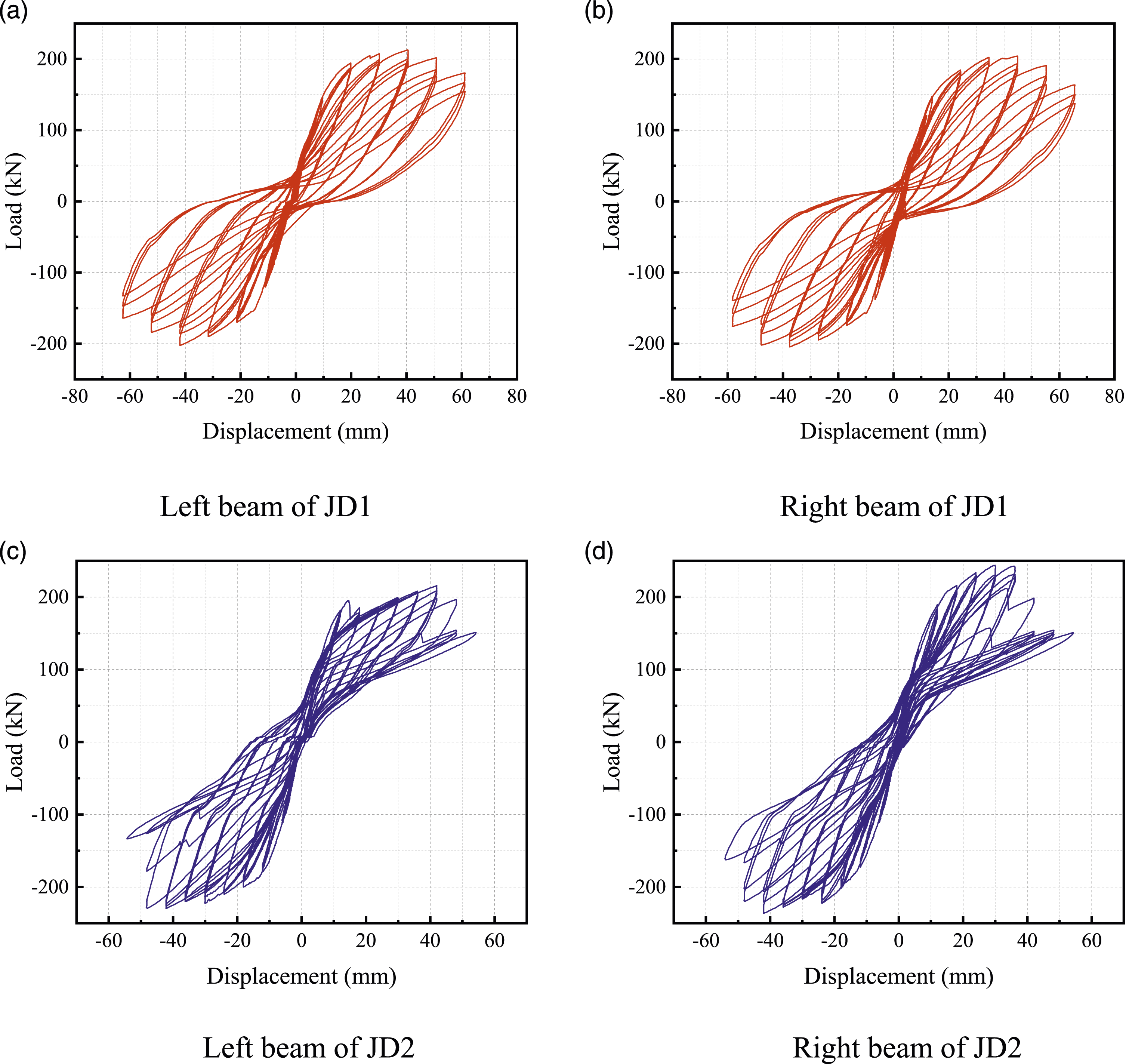
As shown in Figure 9(a) and (b), the hysteretic curve of JD1 presented the typical flag shape of the self-centering structure. With the loading increase, the hysteresis loop tended to be full, showing that the joint still had good energy dissipation capacity under high load. As shown in Figure 9(c) and (d), at the middle of the loading, the area surrounded by the JD2 hysteretic curve was larger. Some dissipaters slid from the bearing with the load increase. When the displacement-controlled load reached 7Δy, due to the insufficient anchoring force of the bearing, some dissipaters separated from the bearing. When the displacement-controlled load reached 8Δy, some threads at the end of dissipaters broke suddenly, leading to a sudden drop in the bearing capacity of the specimens. With most dissipaters breaking, the hysteretic loops became narrow and asymmetric. Due to prestressed force, JD2 could continue to work after the dissipaters broke.
Compared with the hysteresis curves obtained by the similar joints with external energy dissipaters in the references (Wang et al., 2018, 2019a, 2019b), the hysteresis curve of JD1 in this study is relatively fuller and the energy dissipation capacity is better. Before the most energy dissipaters of JD2 is out of work, its energy dissipation capacity is also similar with other similar joints with external energy dissipation, which can be concluded that the new external energy dissipater itself has good energy dissipation capacity, but the design of the anchor bearing should be strengthened.
Skeleton curve
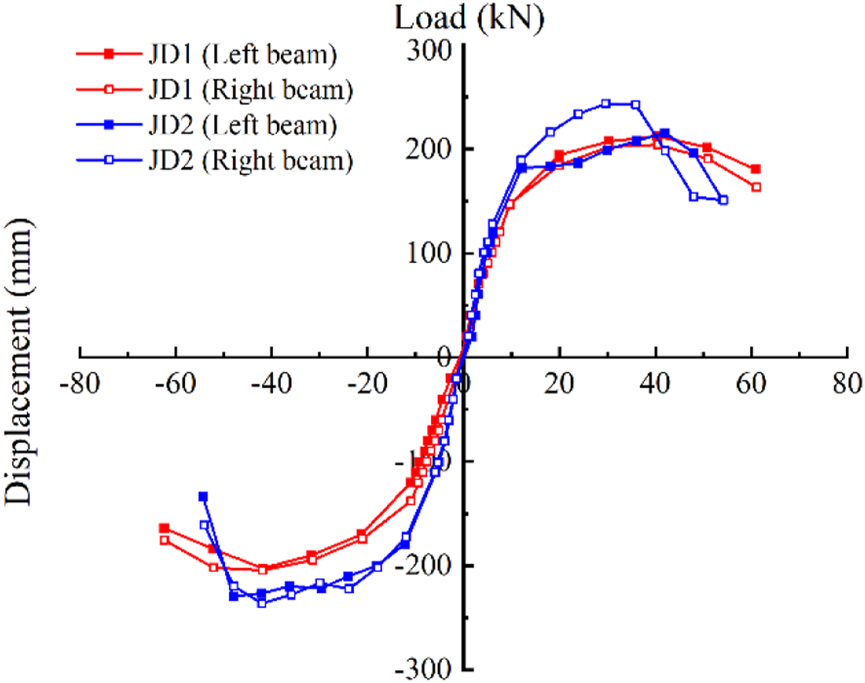
By comparing the skeleton curves of the two joints in Figure 10, in the loading later stage, the bearing capacity of JD2 decreased more noticeably due to the insufficient anchoring force of the bearings. However, in the loading course, the bearing capacity of JD2 was higher than that of the internal energy-dissipating bars. Comparison of the skeleton curves of the left and right beams of JD2, showed that under forward loading, the bearing capacity of the left beam decreased earlier and more significantly; under the reverse loading, the bearing capacity of JD2 first decreased then increased. The main reasons for this phenomenon were as follows: When the displacement-controlled load reaches 3Δy, most of the dissipaters of the joints slip with the bearing, and with the loading displacement increase, the dissipaters gradually separate from the bearing. The sliding between the bearing and the dissipater on the lower side of the left beam is severe. Thus, the dissipaters cannot play a role in energy dissipation in the subsequent loading process, resulting in the significant decline of the bearing capacity of the left beam.
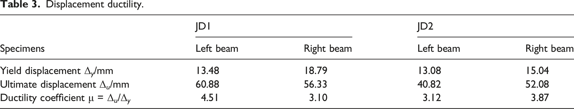
Ductility coefficient
Displacement ductility.
Residual deformation
After unloading, when the load is zero, the deformation of the specimen is defined as residual deformation. The ratio of residual deformation to yield displacement can be denoted as the residual deformation rate μ r (Zhang C et al., 2016), used to analyze the deformation recovery characteristics of the specimens.
Residual deformation rate.
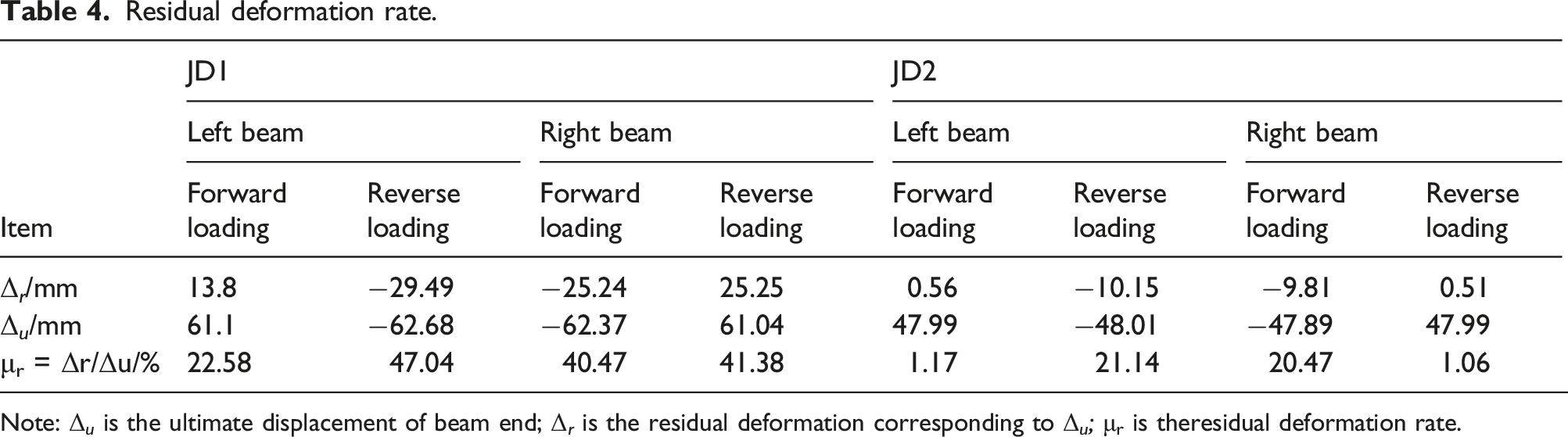
Note: Δ u is the ultimate displacement of beam end; Δ r is the residual deformation corresponding to Δ u ; μr is theresidual deformation rate.
Strain analysis of external dissipaters
In the test, the strain gauges were pasted on the surface of the inner energy dissipation section and outside each external dissipater restrained steel tube to collect strain data. The external dissipaters strain gauges layout is shown in Figure 7. Two external dissipaters were set on the upper and lower surfaces of each beam, respectively. There were eight external dissipaters in total in JD2, and they were numbered in numerical order, as shown in Figure 7.
The strain-time curves of the energy dissipation section and the constraint steel tube shown in Figure 11(a)–(d) correspond to strain gauges JD2 - 1, JD2 - 3, JD2 - 5, and JD2 - 7, respectively. Strain-time curves of JD2. (a) JD2-1. (b) JD2-3. (c) JD2-5. (d) JD2-7.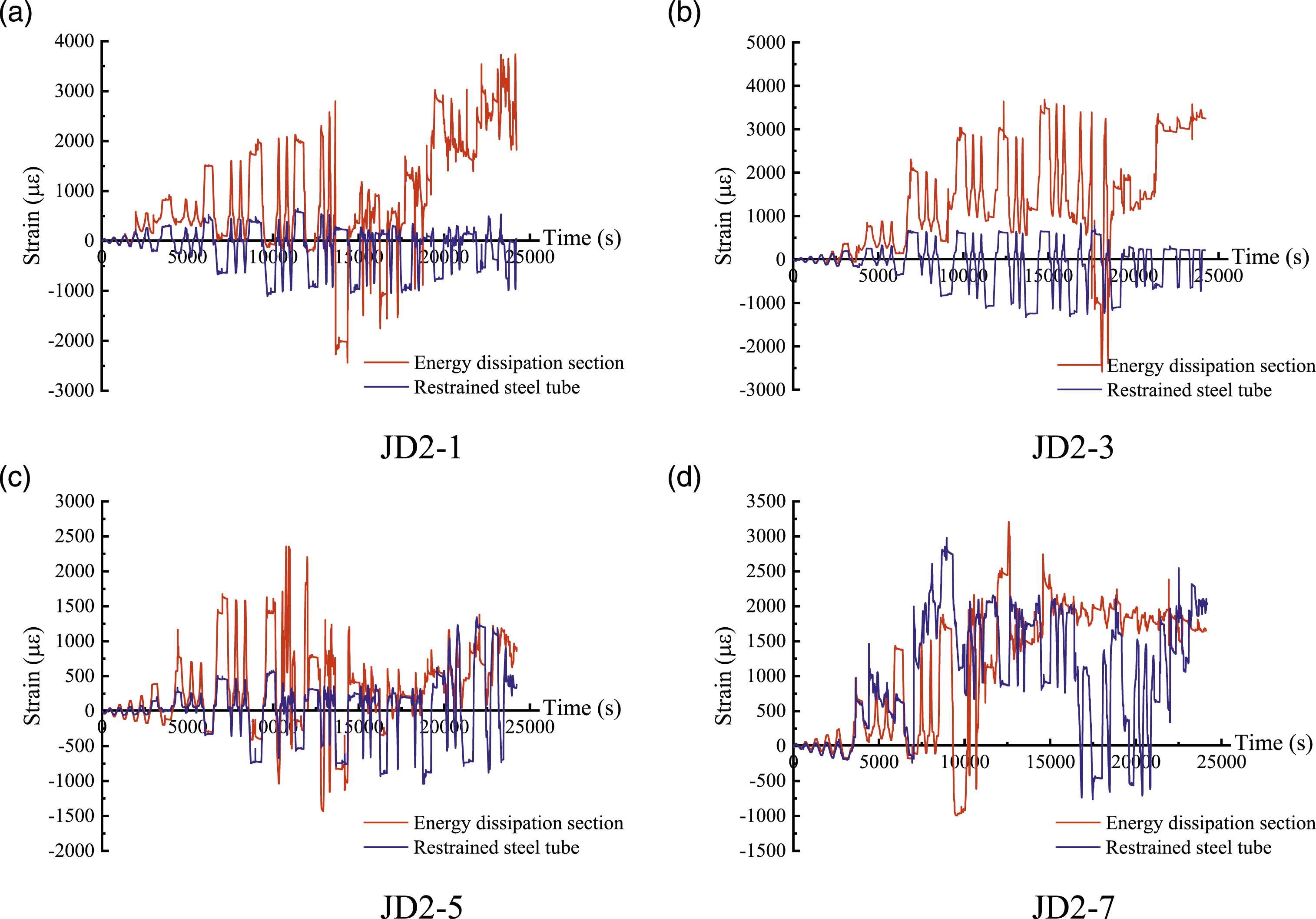
Figure 11 shows the strain variation trend of the energy dissipation section and the restrained steel tube as the applied load increases. The strain of the energy dissipation section was positive, meaning that the energy dissipation section mainly played a role in resisting tension. The strain of the restrained steel tube was mainly negative, meaning that the restrained steel tube played a role in buckling prevention. The energy dissipation section and the restrained steel tube worked together to dissipate energy.
Stiffness analysis of external dissipater
According to the reference (Liu, 2019), the external dissipater is composed of an internal fuse bar (the middle section is weakened to form an energy-dissipating section) and an external restraint system (restrained steel tube and filling material), as shown in Figure 3. Through cyclic tension and compression tests of the dissipaters, the interaction properties of the dissipaters were analyzed. It is considered that the overall stiffness 
Stiffness analysis of dissipation reinforced bar
When the internal fuse bar of the dissipater is in the elastic stage, as shown in Figure 12, according to the axial force balance, the magnitude of the axial force is calculated as: Structure of energy dissipation steel bar.
The length change of the fuse bar can be obtained by calculating the sum of length change of each part; the calculation of the length change of the energy dissipation section and the loading end are as follows:
There is a transition section between the loading end and the energy dissipation section, the length of which is taken as Calculation diagram of transition section.
By integrating the transition section, the length change of the section can be obtained:
Therefore, the total length change of the fuse bar can be expressed as:
The stiffness 
Analysis of restraint system
The restraint system of the external dissipater includes the restrained steel tube and filling material, in which the restrained steel tube and filling material jointly bear the axial force Structure of restraint system (unit: mm).
The section of the restrained steel tube is uniform, and there is no change in section. The change in the length of the steel tube is as follows:
The filling material fills the gap between the restrained steel tube and the energy dissipation steel reinforced bar, and its section changes according to the change in the interface of the energy dissipation reinforced bar. Therefore, it is necessary to analyze the length variation of each part and to summarize it.
In the energy dissipation section and at the end where the load is applied, the length changes of the filling material are as follows:
By integrating the transition section, the change in the length of the section can be obtained:
The change in the total length of filling material can be expressed as:
The stiffness 
Mechanical properties study
Analysis of the stress mechanism
When the load is applied, the core area of the joint bore the axial force, shear force, and bending moment from the beam and column. In this test, the load was applied at the end of the beam. The beam was primarily subject to shear force and bending moment, and the column was mainly subject to the axial force applied on the top of the column. The axial force transferred from the beam end was minimal and, therefore, ignored.
As shown in Figure 15(a), the load at the end of the beam is first transferred to the internal dissipation steel bar for the joint with the internal energy-dissipating bar. The bending moment at the end of the beam is transformed into the axial force acting on the energy dissipating reinforcement; it is transmitted to the core area of the joint through the cushion between the beam and the column. At this time, the core area of the joint is subjected to shear force. Because of the reversed load at the beam end, the directions of the shear forces Stress analysis of the core area of the joint. (a) The joint with internal energy-dissipating bar. (b) The joint with external dissipater.
For the joint with external dissipater, as shown in Figure 15(b), the bending moment at the beam end is transferred first to the bearing of the energy dissipater embedded in the beam, and then to the energy dissipater through the bearing. Taking the left beam as an example, when transferred to the core area of the joint, the bending moment
Stiffness analysis of the joint with external dissipater
As shown in Figure 16, when the joint with external dissipater bears the load at the beam end, the point O is taken as the rotation center, and the relative rotation occurs between the beam and column, resulting in the rotation angle θ. At this time, the specimen is in the elastic stress state, and the prestressing tendon is in the tension state. The external dissipaters are assumed to be represented as a spring with the stiffness K
fuse
. The dissipaters on the top of the beam are compressed, and those at the bottom are stretched. As the center of rotation changes with the stress state of the joint, the dissipaters length variations at the top and bottom of the beam are unequal, as shown in Figure 16. The length change of the beam’s top dissipater is taken as Schematic diagram of the beam-column corner of the joint with external dissipater.
Therefore, the axial forces of the external dissipaters on the top and bottom of the beam can be expressed as:
As shown in Figure 16, to resist the bending moment 

The relationship between the forces F'rud and F'rdd, the post-tensioning force T
p
, and the bending moment M
rb
caused by the axial deformation of the external damper is as follows:
Therefore, according to the rotational stiffness definition, the rotational stiffness of the joint with external dissipater can be expressed as: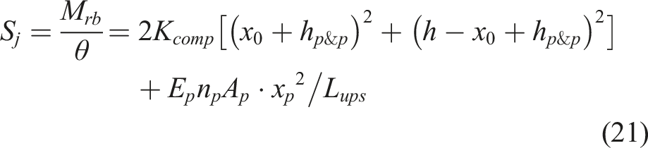
At the initial loading stage, the applied load is small, and the neutral axis can be considered to be located at the center of the beam section. At this time, the section’s compressive zone depth can be taken as x
0
= h/2, and the distance between the prestressing tendon and the neutral axis can be taken as x
p
= 0. Furthermore, the initial rotational stiffness of the joint can be calculated as follows:
Stiffness analysis of the joint with internal dissipation steel bar
When the joint with the internal energy-dissipating bar bears the load applied at the beam end, the point O acts as the rotation center, and the relative rotation occurs between the beam and column, resulting in the rotation angle θ. At this time, the energy-dissipating bars arranged in the upper part of the beam are in a compression state, and those in the lower part of the beam are in a tension state. As the rotation center position changes with the stress state of the joint, the length changes of the energy-dissipating bars on the upper and lower part of the beam are inconsistent. In this state, the strains of the upper and lower energy dissipation bars and the additional strain of the unbonded prestressed bars caused by the gap at the junction should be calculated according to the plane cross-section assumption (JGJ/T 140-2019, 2019).
As shown in Figure 17, to resist the bending moment M
rb
that rotates the beam and column rotate relative to each other, the internal energy-dissipating bar and prestressing tendon work simultaneously. The calculation of the bending moment M
rb
is as follows: Schematic diagram of the beam-column corner of the joint internal energy-dissipating bar.
Therefore, according to the rotational stiffness definition, the rotational stiffness of the joint with internal energy-dissipating bar can be expressed as: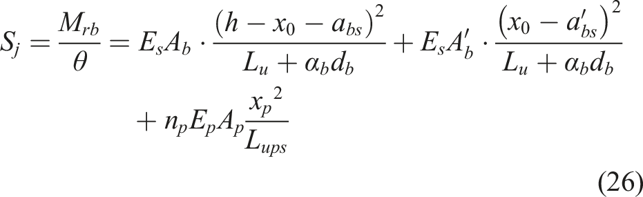
At the initial loading stage, the applied load is small, and the neutral axis can be considered to be located at the center of the beam section. At this time, the depth of the compressive zone of the section can be taken as x
0
= h/2, the distance between the prestressing tendon and the neutral axis can be taken as x
p
= 0. The reinforcements are symmetrically arranged in the joint with an internal energy-dissipating bar, 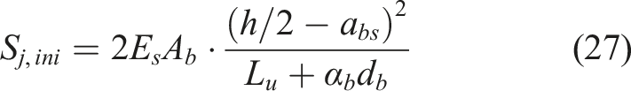
Discussion of the initial rotational stiffness
Moment-rotation curves. (a) JD1. (b) JD2.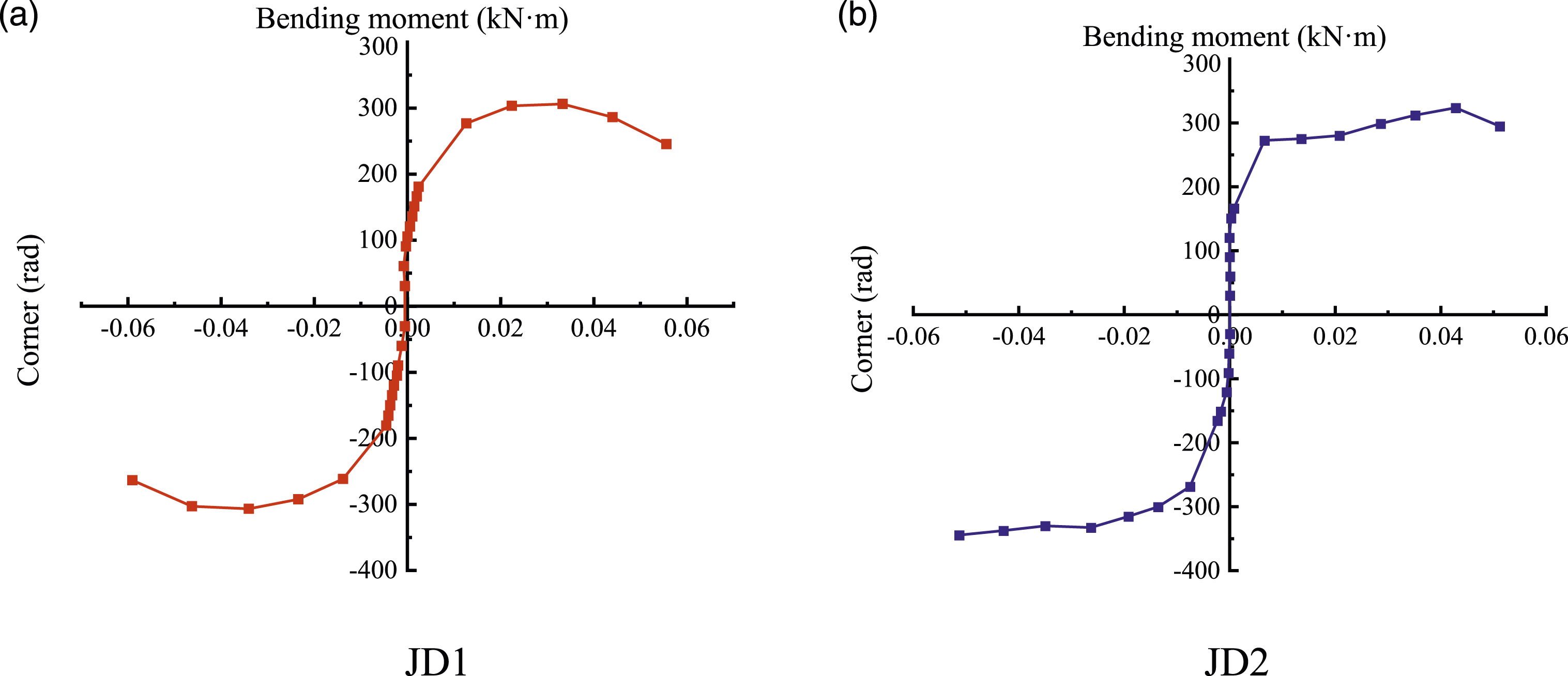
Comparison of the initial stiffness test value and theoretical value of the joints.
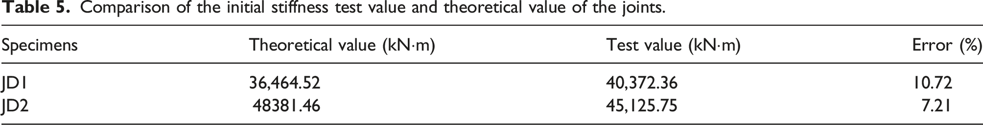
According to EC3 (BS EN 1993-1-8, 2005), if the joint’s initial rotational stiffness meets the requirement, the joint is defined as a semi-rigid connection. According to the section size and material properties of the joints,
Table 5 shows that the difference between the theoretical and experimental values of JD1 is 10.72%, and the difference between the theoretical and experimental values of JD2 is 7.21%. In addition, both the experimental and theoretical results showed that the initial rotational stiffness of JD2 was higher, JD2 had better resistance to deformation. Therefore, the calculation formula of the initial rotational stiffness of the two joints proposed in this paper is reasonable.
Anchoring system for the energy dissipater installation
The specific anchoring systems for the external energy dissipaters in the test are shown in Figure 19. For the convenient installation of the energy dissipaters, notches were made on the connection between the end of the energy dissipaters and the original beam bearing, as shown in Figure 19(a). However, the test result showed that, when sustaining great force in the test, the energy dissipaters at the lower right beam separated from the beam bearing, resulting in a sudden loss in bearing capacity of the whole construct. Anchoring system for the energy dissipater installation. (a) Original bearing of energy dissipater. (b) Modified bearing of energy dissipater. (c) Separation-type installation of modified bearing of energy dissipater.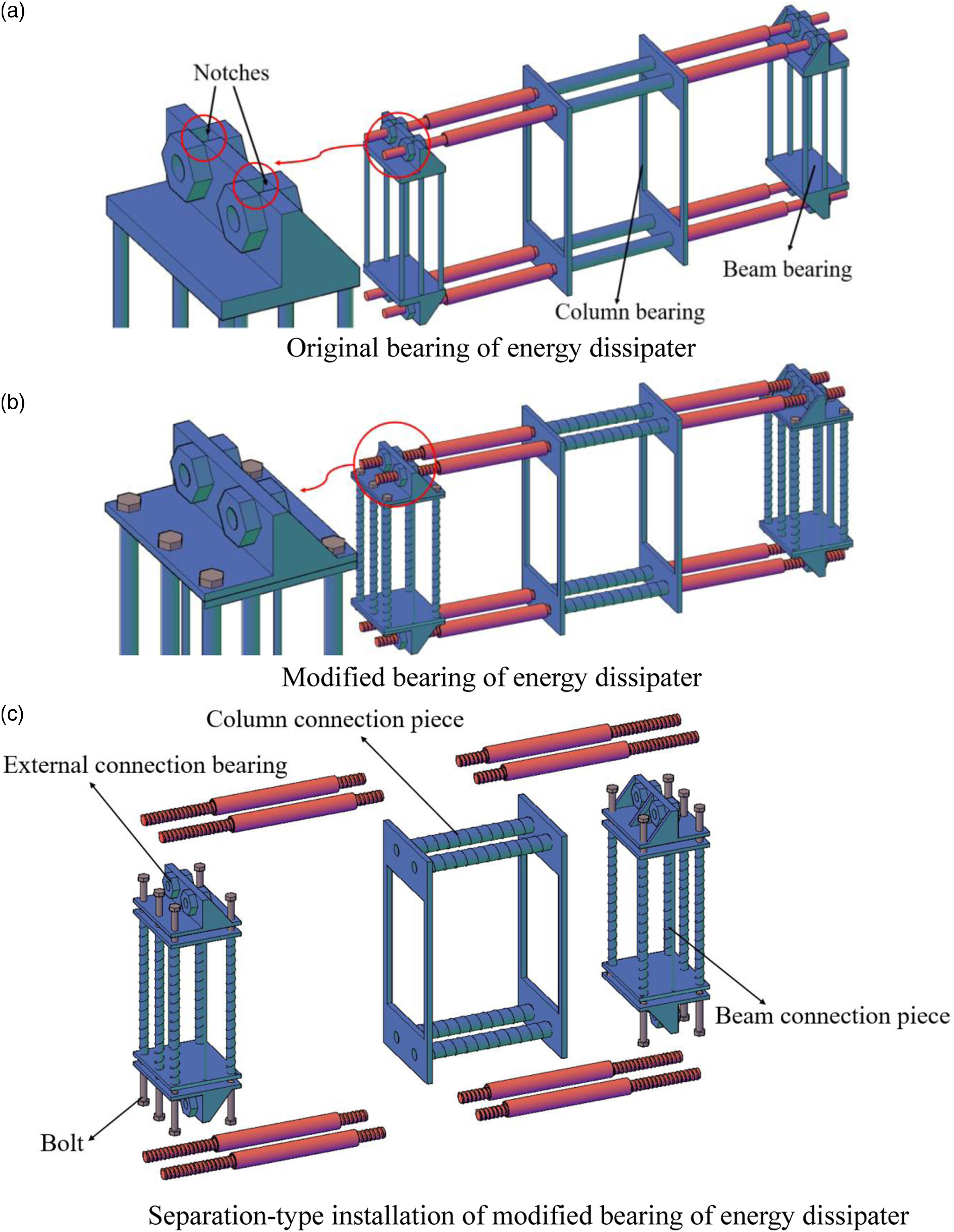
Therefore, a modified design of an anchoring system for the energy dissipaters was proposed, as shown in Figure 19(b). The modified bearing has no gap at the beam end and is completely closed around the bolt holes connected to the beam end and the dissipater, which prevents the dissipater from slipping off the bearing and ensures the effectiveness of the bearing connection.
Moreover, to meet the requirements of easy installation of the energy dissipaters and easy disassembly after an earthquake, a separation design on the modified bearing at the beam end was made, as shown in Figure 19(c). It was divided into three parts: beam bearing, bolt, and external connection bearing. In addition, setting thread on the vertical anchor bar of the modified bearing and the exterior of the transversely connected steel tube can ensure the reliability of the bearing connection. The anchoring bearing construction can significantly improve the anchorage capacity and ensure energy dissipation performance.
Conclusion
In this paper, two types of prestressed concrete frame joints with different energy dissipation designs, namely, joints with internal energy dissipation rods and joints with external energy dissipaters, are investigated by combining low reverse cycle loading tests, and theoretical analysis. The conclusions are as follows. (1) Both joints showed concrete failure at the end of the beam, and only some diagonal cracks appeared in the core area of the column. Compared with the two joints, the joints with external dissipater had fewer cracks and higher bearing capacity. The ductility coefficients of both joints are greater than 3, indicating that both joints have good ductility. During the loading process, some of the supports connected between the external energy dissipator and the beam end slip or even fall off, which does not effectively exert the energy dissipator’s energy dissipation capacity, resulting in the ductility coefficient of the external energy-dissipating joint is slightly lower than the internal energy-dissipating joint. (2) In this test, the diameter of the energy dissipating bar in the external energy-dissipating joint is the same as that of the steel bar in the internal energy-dissipating joint, but its section height is higher, so the theoretical bearing capacity of the external energy-dissipating joint is higher. However, the failure of the external energy dissipator in the test mainly occurred at the end thread. This is not in line with the actual design intention, therefore, in the application of beam column connections, the complex stress state of the external energy dissipator should be considered. In the subsequent studies, the diameter of the thread section at the end of the energy dissipator can be increased to ensure that the failure position occurs at the energy dissipator. (3) The calculation formulas of the initial rotational stiffness of the two joints were derived by combining the stress state and stiffness analysis of the joints with external dissipaters and with an internal energy-dissipating bar. In terms of the initial rotational stiffness, the error between the theoretical calculation value and the experimental value of the joint with internal energy-dissipating bars is 10.72%, and the error between the theoretical calculation value and the experimental value of the joint with the external energy dissipaters is 7.21%. By comparing with the definition of a semi-rigid joint in EC3, it was found that the two joints were semi-rigid. Meanwhile, the initial rotational stiffness of the external energy dissipation joint is higher than that of the internal energy-dissipating joint. (4) Based on the insufficient anchoring capacity of the bearing in the test, a new anchoring system was proposed. It can effectively anchor the external energy dissipator and solve the insufficient anchoring capacity, which can ensure the energy dissipation performance under an earthquake. The anchorage system can meet the requirements of easy installation and easy disassembly after an earthquake, and can be popularized.
Footnotes
Acknowledgements
Thanks to the teachers and students of the structural laboratory of Beijing university of architecture and civil engineering for their kind help for our tests.
Declaration of conflicting interests
The author(s) declared no potential conflicts of interest with respect to the research, authorship, and/or publication of this article.
Funding
The author(s) disclosed receipt of the following financial support for the research, authorship, and/or publication of this article: This paper is funded by the Natural Science Foundation of Beijing (8202011), The Fundamental Research Funds for Beijing University of Civil Engineering and Architecture (X20056) and Beijing University of Civil Engineering and Architecture Pyramid Talents Cultivation Project (JDYC20160205).