
Abstract
A steel plate shear wall (SPSW) system capable of providing strength and stiffness under normal load conditions and dissipating energy under extreme load conditions is proposed. The infill plate of this proposed Segmented Energy Absorbing SPSW (SEA-SPSW) system consists of two trapezoidal plate segments. For each plate segment, one edge is connected to the beam while the opposite edge is joined together by steel strips. The steel strips are held together using high strength bolts with long-slotted holes. Under normal load conditions, the SEA-SPSW behaves like a conventional SPSW. However, under extreme load conditions, the plate segments will slide between the steel strips and dissipate energy through friction. Because the proposed system does not rely on yielding or buckling to dissipate energy, it can be reset and reused after a severe load event. The behavior of this SEA-SPSW is studied using finite element and compared to an all steel conventional SPSW system. It is found that the proposed system not only helps reduce inter-story displacement, it also offers a desirable equivalent viscous damping ratio as well as a rather favorable energy dissipation to mass ratio.
Keywords
Introduction
Conventional steel plate shear walls (SPSWs) are often designed to behave elastically under normal lateral load conditions, but they are expected to yield and absorb energy through inelastic hysteresis under extreme load conditions. Depending on the width-to-thickness ratio and boundary conditions, these SPSWs may experience inelastic out-of-plane buckling. Therefore, maintaining structural integrity and preventing building collapse are dependent upon their post-buckling behavior.
Researchers and engineers have developed ideas of using SPSWs as lateral load resisting systems since 1970s (Zirakian and Boyajian, 2016) due to their efficient and unique performance under both seismic and wind loads, especially in high-rise buildings. SPSW systems can provide high stiffness and high strength along with stable hysteretic characteristics and high plastic energy absorption capacity (Hosseinzadeh and Tehranizadeh, 2014a, 2014b; Kulak et al., 2001; Ma et al., 2022a, 2022b; Sabouri-Ghomi and Roberts, 1991). SPSWs have also been studied and used in rehabilitation of existing lateral load resisting systems, since they can be fabricated and attached to the existing steel structure relatively easily. The Federal Courthouse in Seattle (23-story) and the Sylmar Hospital in Los Angeles (six-story) in the United States, and the Kobe Office Building (35-story) in Japan are examples of buildings that used the SPSWs as seismic load resisting system. The mid-rise Sylmar hospital and the high-rise Kobe office building have both successfully resisted major earthquakes with no major structural damage, in the 1994 Northridge and 1995 Kobe earthquakes, respectively (Astaneh-Asl, 2000; Sabouri-Ghomi et al., 2005; Seilie and Hooper, 2005). Due to an increased interest in using SPSW systems in earthquake resistant design, various codes and standards in the United States and Canada have provided design guidelines for these systems (ANSI/AISC 341-10, 2010; Bruneau et al., 2007; CAN/CSA S16, 2009; Sabelli and Bruneau, 2006).
In general, there are four main configurations for the web plate in SPSW systems: unstiffened SPSWs, stiffened SPSWs, composite SPSWs, and perforated SPSWs.
Unstiffened steel plate shear walls
The infill plate of this SPSW system is an unstiffened thin plate (Alinia and Dastfan, 2006; Bruneau and Bhagwagar, 2002; CAN/CSA S16, 2001) which resists the lateral loads through diagonal tension field action, and at higher load levels by yielding of the infill plate (Astaneh-Asl, 2000; Purba and Bruneau, 2015; Sabelli and Bruneau, 2006; Sabouri-Ghomi et al., 2005). The boundary element (columns and floor beams) are designed to allow this tension field action to develop.
Tromposch and Kulak (1987) performed experimental study on the hysteresis behavior of these SPSWs under quasi-static cyclic loading and developed analytical tension-only strip model to evaluate their ultimate capacities and strengths. Elgaaly (1998) proposed analytical equivalent truss elements in tension (with elastic-perfectly plastic material model) for both welded and bolted shear walls that resulted in good correlation when compared to their test results. Roberts and Sabouri-Ghomi (Roberts, 1995; Roberts and Sabouri-Ghomi, 1991; Sabouri-Ghomi and Roberts, 1991) concluded that the unstiffened SPSWs would provide stable S-shaped hysteresis curves and proposed hysteretic model for these walls.
As a result of out-of-plane buckling of the infill plate, unstiffened SPSW systems are sensitive to initial imperfections which can result in instability even under service loads (Roberts and Sabouri-Ghomi, 1991). Moreover, the thickness required for the web plates of low-rise buildings is usually smaller than the practical thickness. However, the use of larger plate thickness will increase the demand on adjacent frame elements (Jin et al., 2016).
Stiffened steel plate shear walls
Due to the low shear-buckling capacity of thin SPSWs, researchers (Takahashi et al., 1973; Alinia and Dastfan, 2007; Dubina and Dinu, 2014; Guo et al., 2017; Sabouri-Ghomi et al., 2005) investigated SPSWs strengthened using various types of stiffeners. Sabouri-Ghomi and Sajjadi (2012) performed experimental and theoretical research on two similar single span single story SPSWs with one reinforced by multiple horizontal and vertical stiffeners. Their results showed that while the increase in shear strength was insignificant, a noticeable increase in shear stiffness and dissipated energy was observed for the stiffened SPSW. Nateghi-Alani and Alavi (2009) and Nateghi-Alani and Khazaei-Poul, 2013) conducted theoretical and numerical analyses on various stiffened SPSWs and showed that the use of diagonal stiffeners in SPSW systems would enhance both their shear buckling strengths and hysteresis behavior. Alavi and Nateghi (2013) performed experimental tests on diagonally stiffened steel plate shear walls with central perforation to demonstrate their effectiveness. Yu and Hao (2016) studied the effect of stiffeners and connection rigidity on the cyclic behavior of SPSWs. They concluded that adding stiffeners to the SPSWs would enhance their dynamic behavior and reduce the demand on adjacent beams and columns. However, studies reported by Alinia and Sarraf Shirazi (2009) and Dubina and Dinu (2014) have shown that the ductility of heavily stiffened SPSWs tend to be lower when compared to thin SPSWs. Yu et al. (2020)performed experimental and numerical studies to investigate how the use of partially encased composite columns as vertical boundary elements could enhance the initial stiffness, maximum energy dissipation and ductility of SPSWs. Using ABAQUS, Ma et al. (2022b) investigated the seismic performance of four different kinds of steel plate shear walls (flat SPSW, SPSW with vertical slot in the middle, SPSW reinforced with orthogonal stiffeners, and SPSW with slits adjacent to the columns) before and after corrosion. They concluded that the SPSW reinforced with orthogonal stiffeners performed the best in terms of ultimate shearing strength, initial stiffness, energy dissipation, and ductility
Composite steel plate shear walls
While stiffened steel plates can enhance shear buckling strength and allow shear yielding to occur without shear buckling, welding stiffeners to the steel plates add weight to the system and result in extra cost. It could also create out-of-plane imperfections. As a result, investigators have proposed the use of composite SPSWs (CSPSWs) in which concrete and other materials are added to one or both sides of the steel plate to improve their strength, ductility and energy dissipation capacities. Guo et al. (2012) performed an experimental research to compare the hysteretic behavior of SPSW and CSPSW. He showed that beyond the story drift ratio of 1/200, CSPSW would develop higher strength and energy dissipation capacity than the corresponding SPSW system. Amani et al. (2013) studied the use of precast cover panels in CSPSW systems, and concluded that the efficiency of these cover panels would improve by the use of bilateral as opposed to unilateral cover panels. These cover panels also provide thermal and acoustics insulation to the structure. Rahai and Alipour (2011) investigated a type of CSPSW reinforced by fiber-reinforced polymer (FRP) strips, and concluded that FRP strips had a noticeable contribution to the lateral load resisting of the system once the steel panel had fully yielded. Nateghi-Alahi and Khazaei-Poul (Nateghi-Alahi and Khazaei-Poul, 2012, 2013) conducted experimental and analytical studies on the cyclic behavior of SPSWs strengthened by Glass FRP layers. They showed that the cumulative dissipated energy, secant stiffness, yield strength, ultimate shear strength and post-buckling strength all increased if the laminates were oriented in the direction where tension field developed. Jin et al. (2016, 2017) proposed a slotted composite SPSW system by providing concrete panels on both sides of an inclined slotted steel plate. They showed that the system exhibited ductile behavior and a stable hysteresis loop.
Although CSPSWs are beneficial from both a strength and stiffness standpoint, they are more costly to build than thin SPSWs (Sabelli and Bruneau, 2006).
Perforated steel plate shear walls
A design that allows for the use of thicker infill plate without inducing larger forces in the boundary elements of a SPSW system is to introduce openings in the SPSW panels (ANSI/AISC 341, 2010). Roberts and Sabouri-Ghomi, 1992 conducted experimental study to evaluate the stiffness and strength of a SPSW with circular opening at its center. The system demonstrated stable S-shaped hysteresis behavior and acquired sufficient ductility without noticeable loss in load capacity. (Valizadeh et al., 2012) performed tests on eight SPSWs with a single circular opening and showed that they exhibited stable S-shaped cyclic behavior for drifts up to 6%. However, their stiffness, strength and the amount of energy dissipation were not as high as those of regular steel plate without the opening. Bhowmick (2014) and Bhowmick et al. (2014) performed numerical analyses on the cyclic behavior of perforated SPSWs, and proposed shear strength equations for centered circular opening on SPSWs as well as other different perforation patterns. (Sabouri-Ghomi and Sajjadi, 2012) evaluated the stiffness and strength degradation of stiffened and unstiffened SPSWs with various opening sizes. They concluded that for stiffened steel plate with single opening designed to permit local buckling of subpanels but prevent general buckling of the wall, the location of the opening would not affect the wall’s strength and stiffness. Egorova et al. (2014) performed experimental study on Ring-Shaped Steel Plate Shear Walls (RS-SPSWs). They showed that the RS-SPSW specimens were capable of providing a hysteresis behavior without significant pinching, but plastic hinges were observed in the rings. Hosseinzadeh and Tehranizadeh (2012) performed nonlinear finite element analysis on the cyclic behavior of SPSWs with stiffened large rectangular openings. They observed that the ultimate strengths and behavior of these SPSWs were not significantly affected by the opening geometries and locations. Meng et al. (2015) conducted numerical analyses on various types of SPSW systems with openings. They concluded that the introduction of openings to a SPSW system would limit the system’s out-of-plane deformations and alter its failure modes. It also reduces the forces transmitted to the vertical boundary elements due to tension field action.
Current study
All the SPSW systems discussed above rely on yielding and/or buckling of the infill steel plate to dissipate energy. This means after a severe loading event, the entire infill plate may need to be replaced as part of the building’s rehabilitation effort. In addition, if energy dissipation is dependent on the development of tension field action in the plate, the force demand placed on the vertical boundary elements of the SPSW system can be quite high. To make reparation somewhat easier and to reduce the force demand on the vertical boundary elements (columns), Guo et al. (2011) and Ozcelik and Clayton (2017) proposed detaching the vertical edges of the plate from the columns. Hajimirsadeghi et al. (2019) recommended the use of modular steel plate panel for their SPSW system, and Ghodratian-Kashan and Maleki (2021) introduced the use of corrugated steel plate shear wall connected only to the horizontal boundary elements (beams) as an effective lateral load resisting system.
In the present study, a new SPSW system referred to as the Segmented Energy Absorbing Steel Plate Shear Wall (SEA-SPSW) is proposed and its behavior is investigated. This SEA-SPSW system not only provides strength and stiffness to the structure under normal loading conditions, it dissipates energy through friction under extreme load conditions without undergoing buckling or yielding. In addition, because the shear wall is shaped in such a way that its vertical edges are not in direct contact with the columns, the columns will not experience high force demand. In addition, they can bend freely without interfering with the proper functioning of the shear wall. More importantly, because the system remains mostly elastic throughout the loading process, it can be reset and reused after a severe loading event. After presenting the general concept behind this SEA-SPSW system, the determination of the proper plate geometry is discussed. Finite element analyses will then be conducted to demonstrate the effectiveness of the proposed SEA-SPSW system.
Segmented energy absorbing-Steel plate shear wall
Plate geometry
One feature of the proposed SEA-SPSW is that the infill plate is only connected to the beams along the top and bottom edges. It is not connected to the columns on the sides so the force demand on these columns is greatly reduced. In addition, the plate is shaped in such a way that the columns are allowed to deflect freely under a lateral load. The connection to the beams can be pinned or fixed for out-of-plane rotation. Based on ANSI/AISC 341-16 (2016) and FEMA 450-1 (2004), plates with an aspect ratio in the range of 0.5 ≤ width/height ≤2.0 will be investigated.
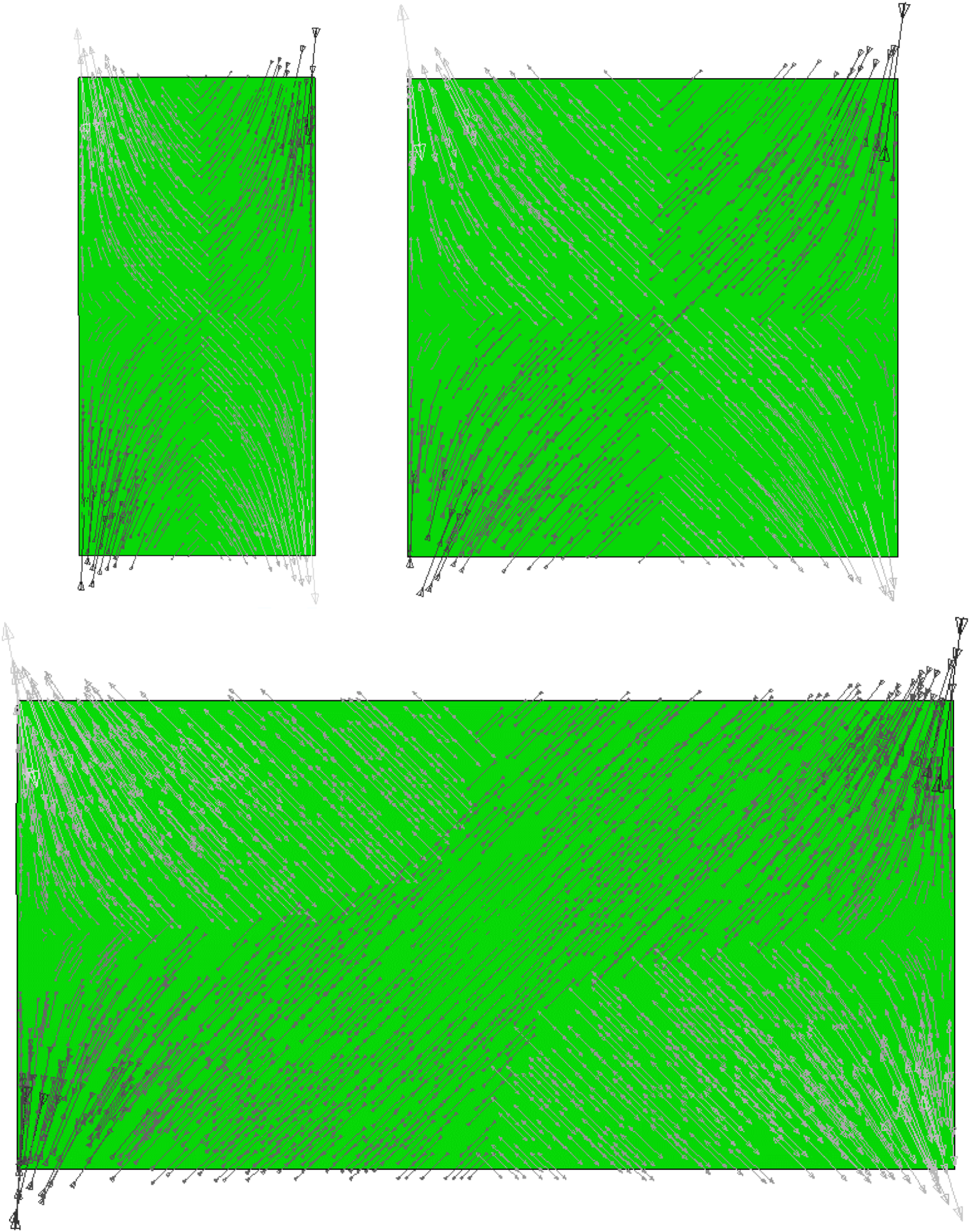
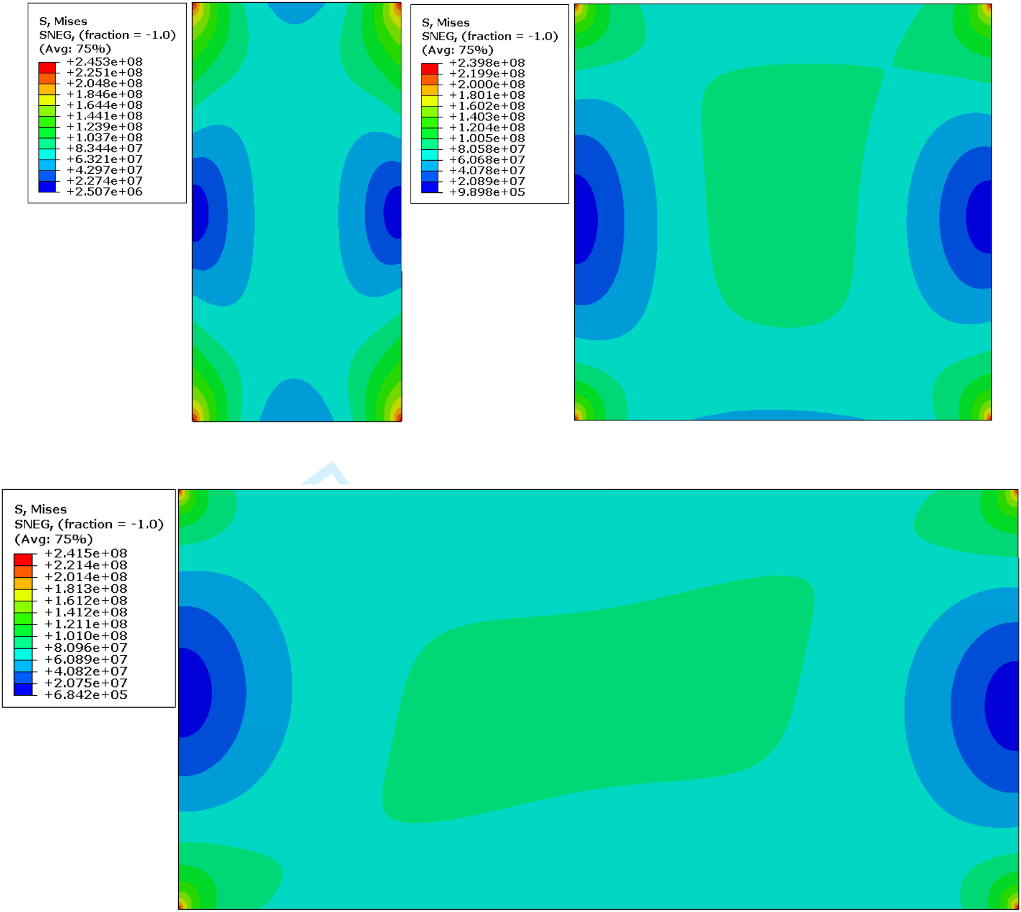
A free body diagram of a plate under a pair of shear forces is shown in Figure 1. The moments acting on the top and bottom edges of the plate are reaction moments needed to keep the plate in equilibrium. In an actual frame, these moments will be carried not only by the beams but also by the floor slabs that are connected to these beams. The principal stress trajectories and the von Mises stresses for three plates with a height h = 3 m and width w = 1.5 m, 3 m and 6 m (i.e., having width-to-height ratios of 0.5, 1 and 2) obtained from a finite element analysis until first yielding using ABAQUS are shown in Figures 2 and 3, respectively. The results were obtained using steel with modulus of elasticity E = 200 GPa and yield stress F
y
= 250 MPa. Note that the stresses are insignificant in regions at the vicinity of the two vertical edges of the plate, indicating that material in these regions can be removed without significantly affecting the load-carrying capacity of the plate. Geometrics and loading condition of shear walls modeled in ABAQUS/CAE 6.14-2. In-plane principal stress trajectories for steel plates with width-to-thickness ratios of 0.5 (top left), 1 (top right), and 2 (bottom). Von Mises stresses (in Pa) for steel plates with width-to-thickness ratios of 0.5 (top left), 1 (top right), and 2 (bottom).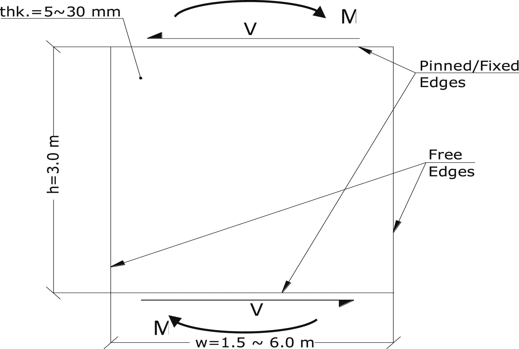
The geometry of the proposed SEA-SPSW is shown in Figure 4. The infill plate is segmented into two trapezoidal pieces by eliminating the side regions (the cross-hatched areas) where the stresses are low. The dimensions a and d were determined to be: a ≈ 0.15n
p
(where n
p
is the smaller of the width w and height h of the plate) and d ≈ 0.42 h. By using the above a and d dimensions, the increase in maximum stresses in the wall by the shear forces V after introducing the cutouts will not exceed 3%. Geometry of the proposed SEA-SPSW (left) obtained by cutting out the cross-hatched triangular areas where the stresses are low (right).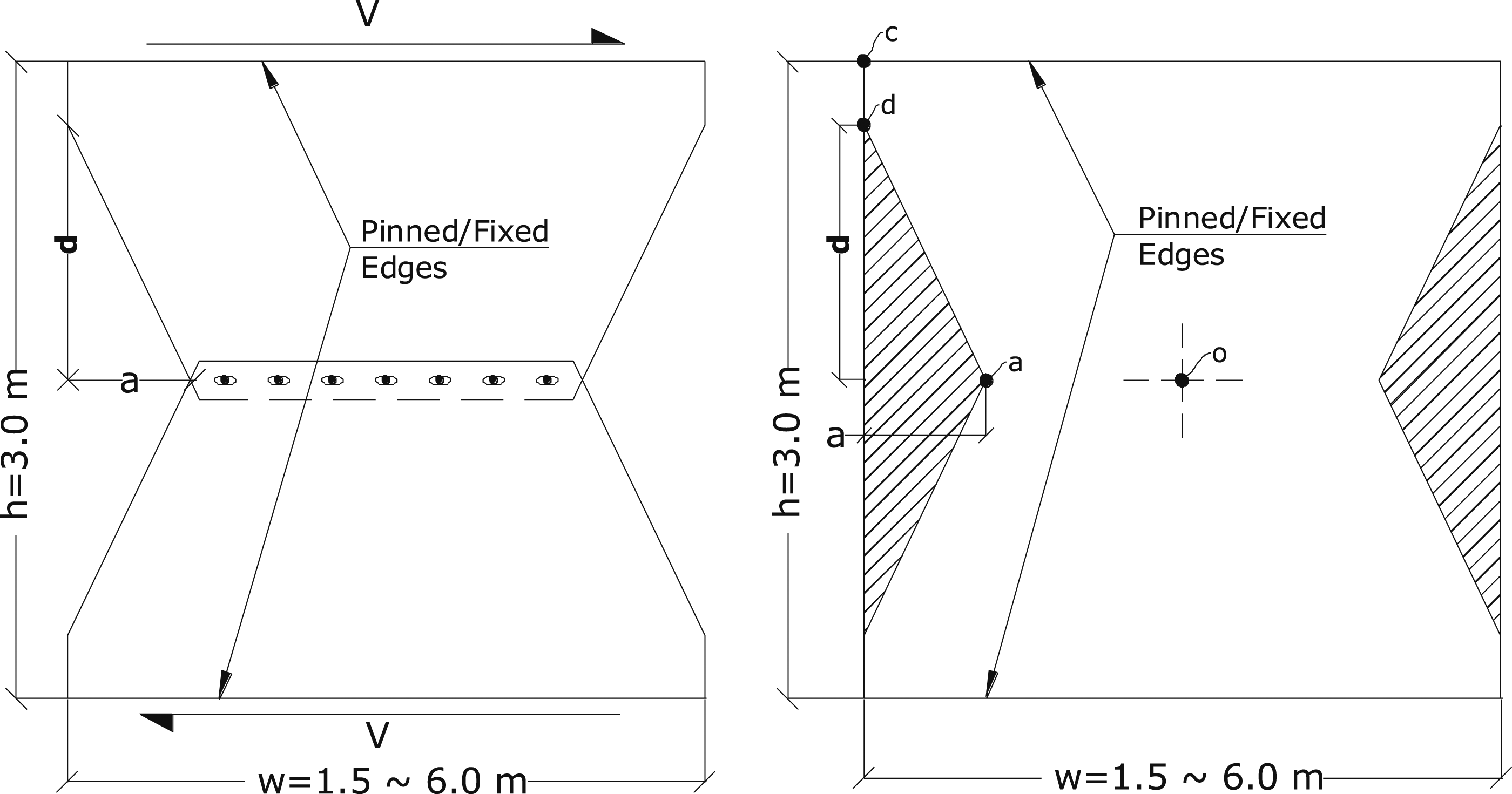
The two trapezoidal plate segments have long slotted holes along their opposing edges and they are connected in the middle by two steel strips clamped together using high strength bolts. The size of the steel strips should be such that an edge distance of about 2d
b
(where d
b
is the bolt diameter) is present on both sides of the bolt (ANSI/AISC 360-16, 2016). Also, to ensure the clamping force does not vary noticeable over the connected region, the spacing of the bolts in the direction of the applied load should fall between 3d
b
and the smaller of 24t (where t is the thickness of the thinner connected parts) or 300 mm (ANSI/AISC 360-16, 2016). A schematic of the system together with the surrounding beams and columns is shown in Figure 5. The clamping force from the bolts is set in such a way that under normal load conditions, the SEA-SPSW provides strength and stiffness to the building like any conventional SPSW; but under extreme load conditions, the plate segments will slide relative to each other between the steel strips and allow energy to be dissipated through friction between the steel plates and the steel strips. Energy dissipation by friction is considered more desirable than that by inelastic buckling because the former often shows stable hysteresis behavior while the latter usually displays some pinching effect. Schematics of the SEA-SPSW.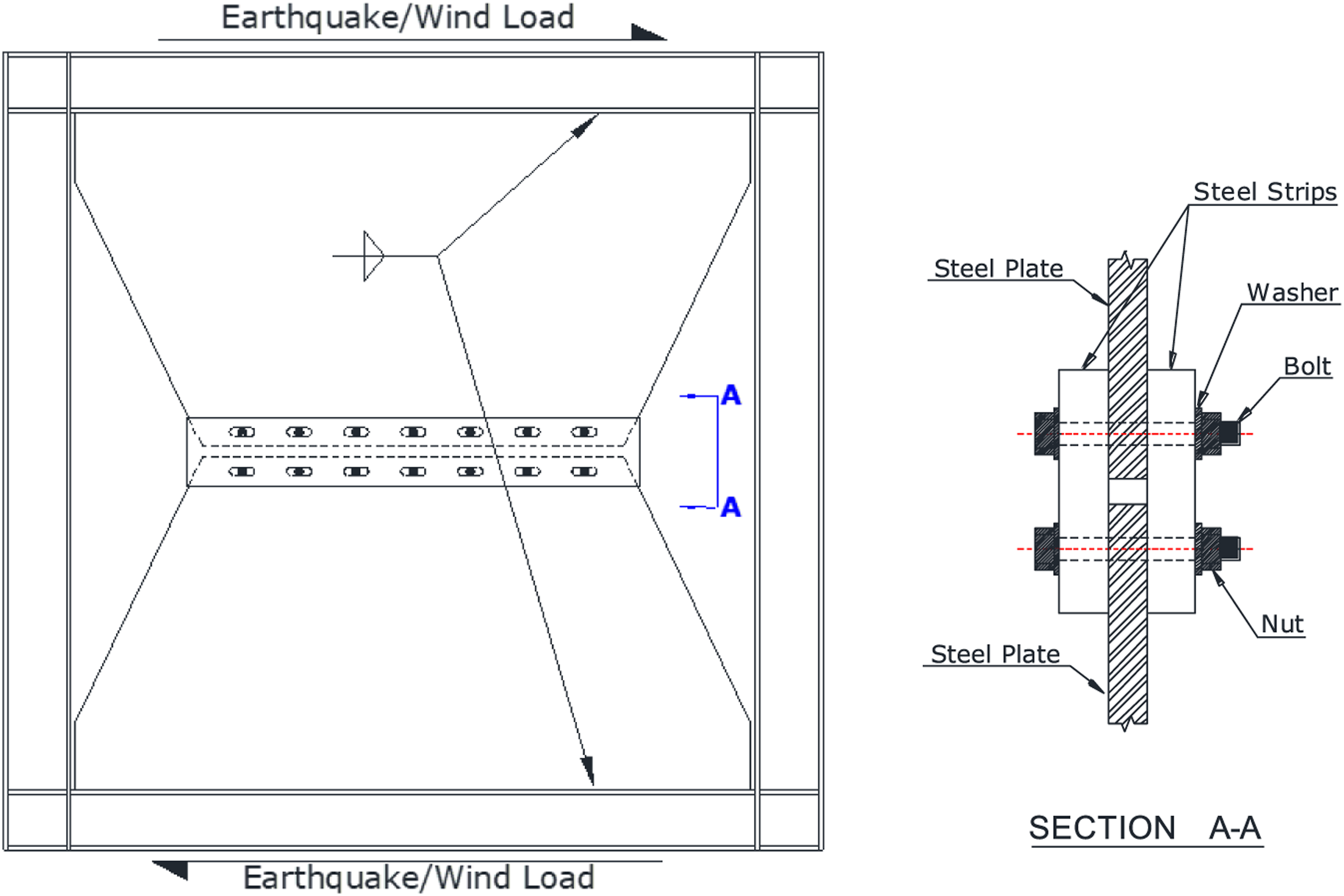
Yielding and buckling
For the proposed system to function as expected, the steel plate shear wall should not undergo buckling or extensive yielding. If yielding is to be avoided so repair will be limited to resetting the plates after a severe loading event, its shear capacity is limited by the steel yield stress F
y
. From the finite element analysis results shown in Figure 3, the maximum stress occurs at the four corners of the plate. Using the von Mises yield criterion at the corner of the steel plate shear wall at the yielding stage Plot of σFE/σTheory versus w/h.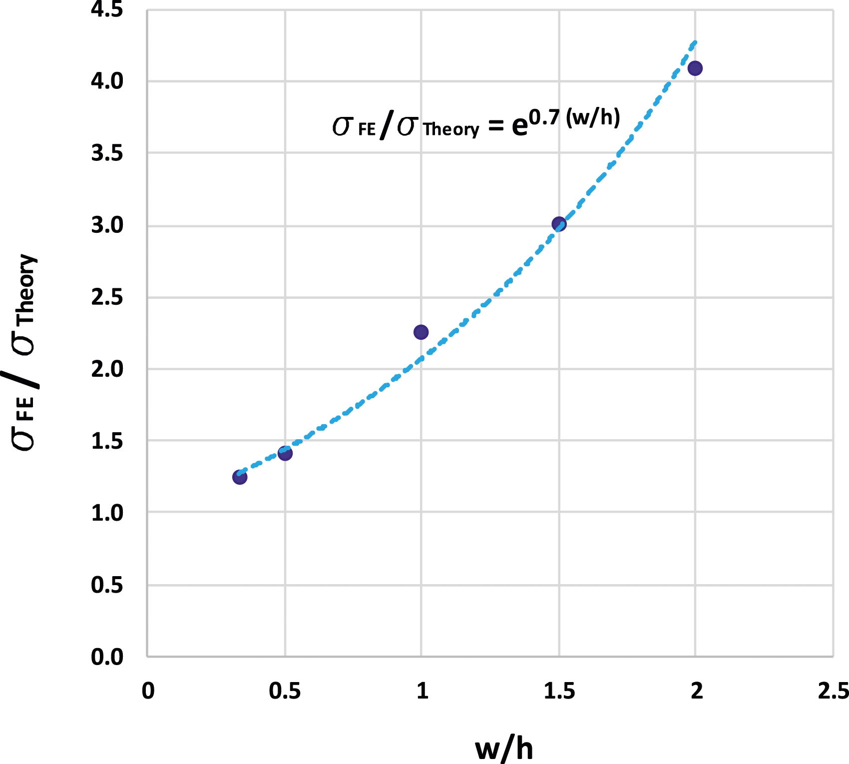

From the figure, it can be seen that a good fit is obtained when

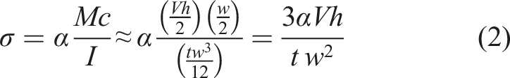
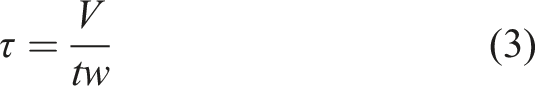
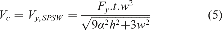
Substituting equations (2) and (3) into equation (1) and solving for V, the shear capacity of the SPSW against yielding can be calculated as
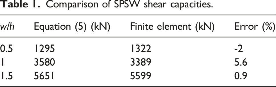
Comparison of SPSW shear capacities.
To avoid plate buckling before yielding occurs, the thickness of the plate must be larger than some critical value. Although Zirakian and Zhang (2015) have proposed equations to determine this critical thickness, their study was based on a plate supported on all four edges under pure shear. Given that the geometry of the proposed SEA-SPSW is trapezoidal in shape and only two edges are supported, their equations are not directly applicable. A finite element analysis was therefore performed to determine this critical thickness. Using ABAQUS’s C3D8R elements and after performing a convergence study, element sizes that vary from 2 mm (in the narrowest middle section of the wall) to 5 mm (in the widest top and bottom sections of the wall) was used to model the steel plate wall with three different aspect ratios (w/h = 0.5, 1 & 2, with h = 3 m), six different thicknesses (t = 5, 10, 15, 20, 25 & 30 mm), and two different out-of-plane boundary conditions (pinned and fixed) for the top and bottom edges of the plates. For each of the 36 plates, two different analyses were performed. First, a buckling analysis was conducted to determine the first buckled mode shape and the magnitude of the applied load V
cr
that corresponds to this buckling mode. Then, the “Static Riks” analysis, which allows for the consideration of material and geometrical nonlinearities, was performed to obtain the yield load V
y
which represents the applied load that causes yielding in the plate based on the von Mises yield criterion. An initial geometric imperfection that corresponds to the first buckling mode with a magnitude below the limit suggested by Behbahanifard et al. (2003) (i.e., less than Vcr/Vy versus h/t plots (the solid and dashed lines represent results for fixed and pinned conditions along the top and bottom edges, respectively).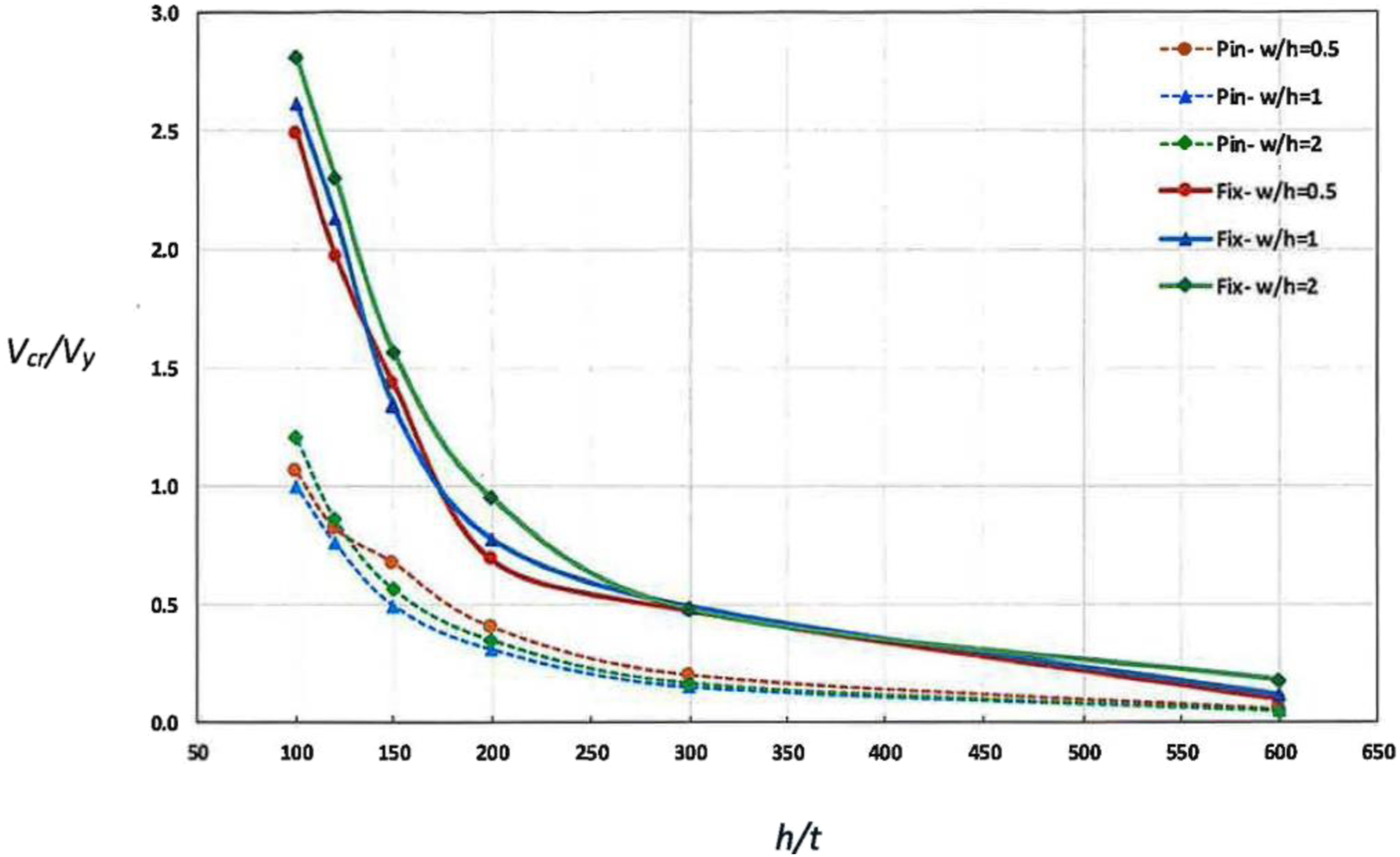
Energy dissipation through friction
Friction dampers (FDs) use friction between moving surfaces to dissipate energy. These dampers are relatively inexpensive to fabricate and install and have been proven to work effectively (Pall and Marsh, 1982; Mualla and Belev, 2002). Since the maximum force developed in these devices are pre-specified, they require minimal inspection and replacement when compared with other types of dampers (Pasquin et al., 2004). They are not particularly sensitive to ambient temperature and they add stiffness to the structure. However, the condition of the friction surface and therefore the friction force may change over time. In addition, since FDs demonstrate bilinear behavior and so linear analysis cannot be used for systems that incorporate FDs in their design.
The cyclic behavior of a friction damper is often represented by a Coulomb model (Hong and Liu, 2000) given by Friction force relationship with (a) velocity (F
friction
vs 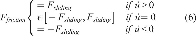
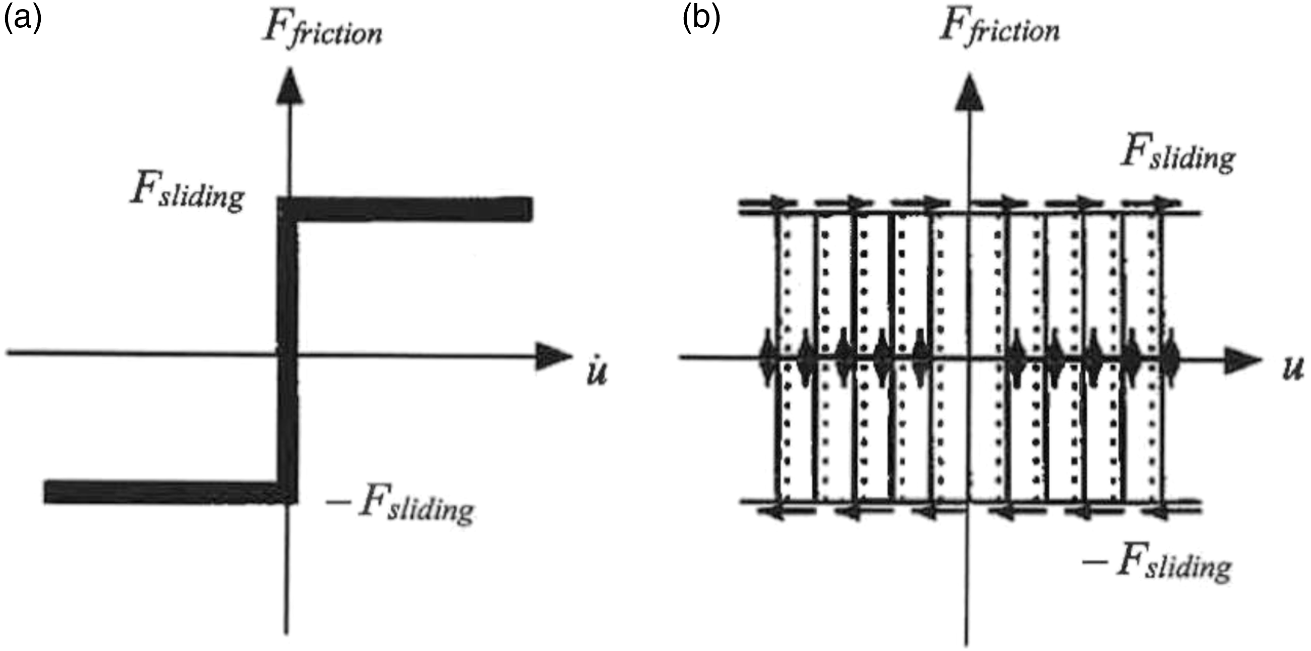
It should be noted that there are two coefficients of friction: the static coefficient of friction μ s associated with static friction, and the kinetic coefficient of friction μ k associated with dynamic friction. Since μ s is always larger than μ k , the static friction force is always higher than the dynamic friction force. In the finite element analysis (to be discussed in the following section), both static and dynamic friction are taken into account in the modeling.
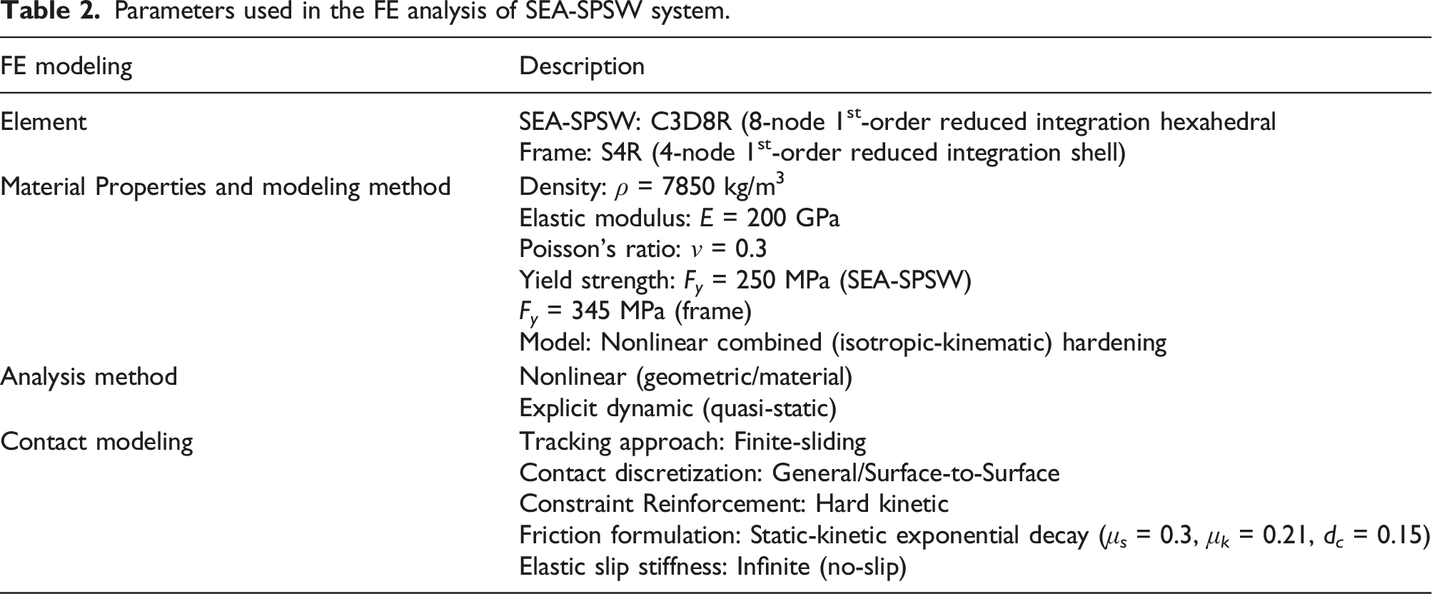
Finite element modeling of SEA-Steel plate shear wall
Modeling of steel strips and steel plates
The steel strips and plates were modeled using C3D8R in ABAQUS. C3D8R is a 3-D hexahedral (first-order solid) element with reduced integration, and ABAQUS Explicit solver was used in the analysis. Yield stress, elastic modulus, and material density used were 250 MPa, 200 GPa, and 7850 kg/m3 respectively. The von Mises yield criterion was used for the material nonlinear analysis. In addition, a combined isotropic-kinematic hardening model was used to capture both the expansion and translation of the yield surface and to account for the Bauschinger effect (Chung and Lee, 2018). This nonlinear combined hardening law is based on the work of Lemaitre and Chaboche (1990), and has been used by other researchers (Berman, 2011; Hedayat et al., 2017, 2019; Purba and Bruneau, 2015; Wang et al., 2015). Based on a convergence study, the maximum element size used to model the steel strips and plates was 5 mm.
Modeling of the friction damper
Quasi-static nonlinear analysis, incorporating both geometrical and material nonlinearities, was used to simulate the behavior of the friction damper under shear force. The quasi-static analysis was performed using the Explicit Dynamic solver in ABAQUS. This solver solves the equations of motion using a forward Euler or central difference algorithm, using information of the previous step to solve for the current step.
Friction between the steel strips and steel plates was modeled using the Interaction feature in ABAQUS. To control the contact behavior, the following modeling techniques need to be defined: “Tracking Approach”, “Contact Discretization”, “Pressure-Overclosure Behavior”, and “Interface Friction Formulation”. Tracking approach specifies the expected relative tangential displacement of two surfaces. Two options, small and finite sliding, are available for use. Finite sliding was used in the current study because it is more general and is available for general contact definition in the Explicit solver. Contact discretization can be specified as “Node-to-Surface” or “Surface-to-Surface”. Surface-to-surface approach was used because it prevents surface penetrations and utilizes a more advanced contact algorithm in the analysis, thus allowing more accurate stress and pressure results to be obtained. The pressure-overclosure relationship allows users to define the relationship between contact pressure and separation at the contact interface. Three algorithms: “Hard”, “Exponential”, and “Linear” are available. Hard contact was selected in this study to prevent tension resistance at the interface (ABAQUS, 2014). Interface friction can be modeled using three methods available in ABAQUS. They are the “Penalty”, “Static-Kinetic Exponential Decay”, and “Lagrange Multiplier” (only available in ABAQUS/Standard) methods. Static-kinetic exponential decay friction formulation as shown in Figure 9 was used in this study. This interface friction method is an extension of the “Penalty” method, which is based on the basic Coulomb friction model, and allows for the introduction of both static and kinetic coefficients of friction and gradual transition between these two conditions. Static-Kinetic Exponential Decay friction formulation in ABAQUS.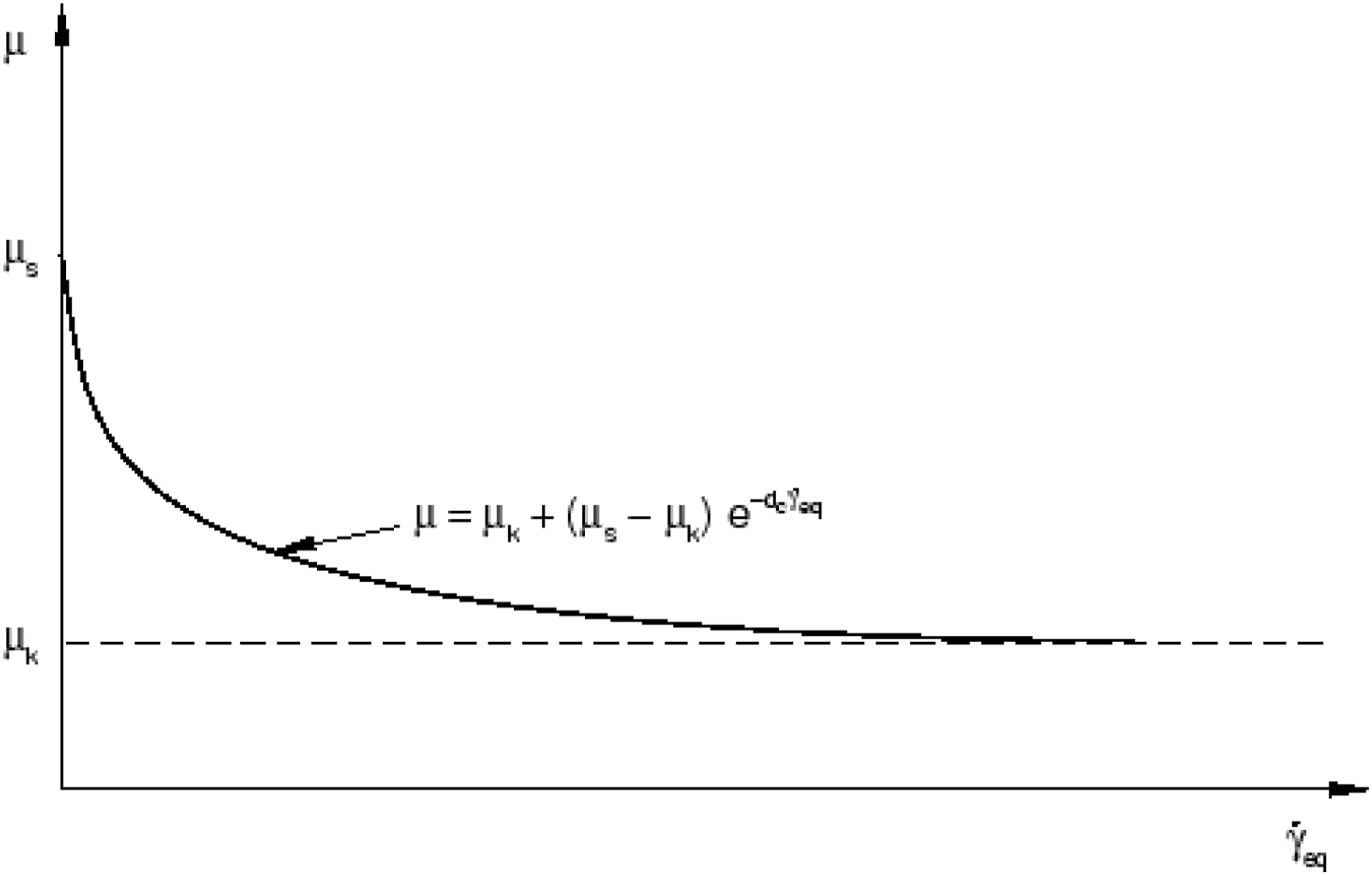
In the “Static-Kinetic Exponential Decay” model, the coefficient of friction takes the form:
The contact surfaces between the steel strips and the steel plates were assumed to be “Class A” (ANSI/AISC 360-23, 2023). It should be noted that ABAQUS Explicit solver uses wave propagation technique to solve the equations of motion. It is therefore essential that the solution time (referred to as time-period for each step in the Explicit analysis) be selected so its value is larger than a minimum value t
p,min
given by (Abaqus 6.14 Documentation Collection,” 2014)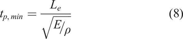
Model validation
The finite element model described in the preceding section to simulate the behavior of a friction damper (FD) is validated herein against an experimental study conducted by Grigorian and Popov (1994) for a steel-on-steel slotted bolt connection using one Belleville washer. The parameters used for the tests and in the FD model are given below: • Plate Material: ASTM A36 – Mill scale steel surfaces: F
y
= 250 MPa, E = 200 GPa, µ
s
= 0.33 • Plate Dimensions: PL 5”x4”x5/8”: h = 127 mm, w = 101.6 mm, t = 15.875 mm • Clamping Force: N
c
= 12.0 kips = 53.4 kN
This clamping force was applied as a pressure load in the “Surface-to-Surface” approach in ABAQUS to model friction behavior as described in preceding section. The amplitudes of the cyclic displacement loading protocol used to simulate the dynamic behavior of this friction damper are given in Figure 10. They are identical to those used by Grigorian and Popov (1994), except that for each displacement amplitude only one instead of 10 similar cycles was applied. The values used for Displacement control cyclic loading protocol for use in the FE simulation study (ABAQUS, 2014).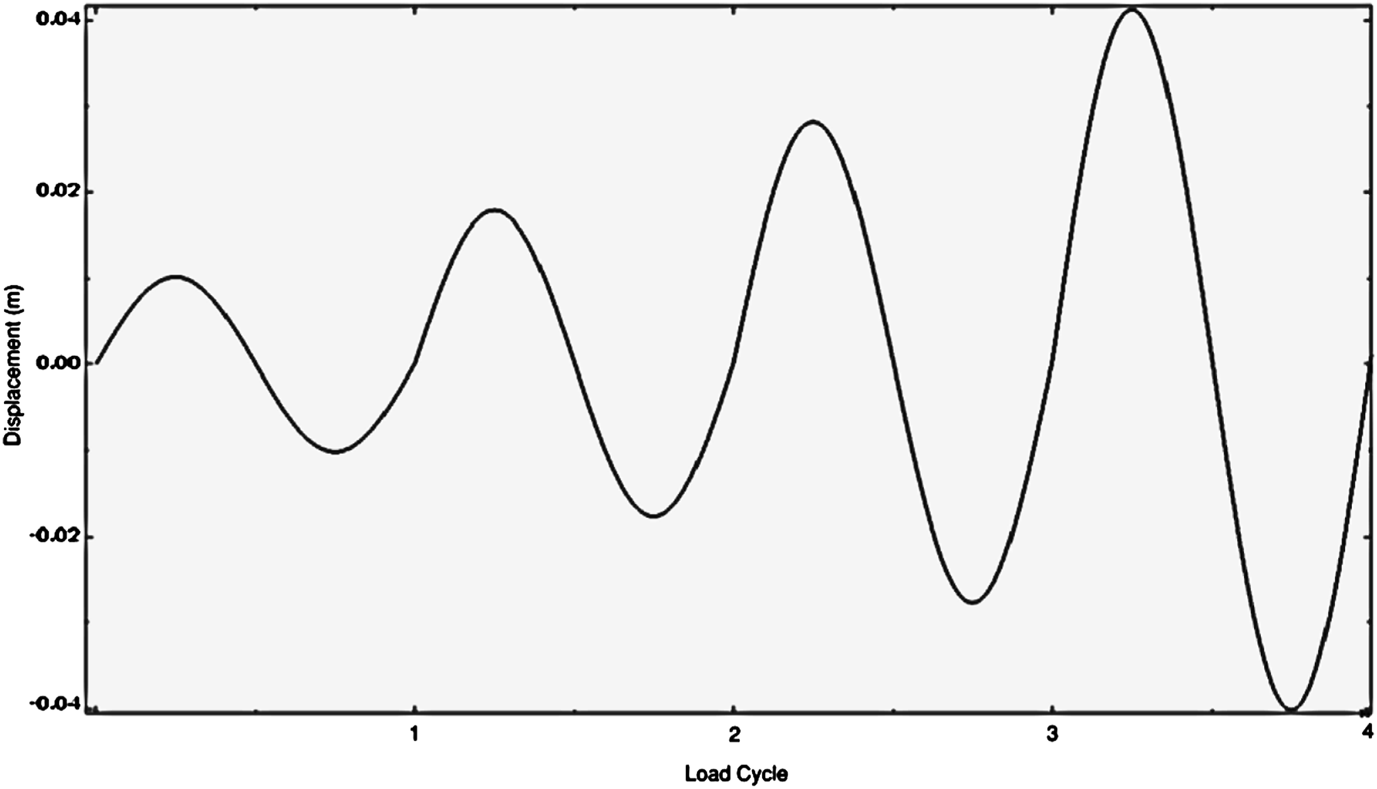
In Figure 11, the hysteresis loops generated using the finite element model are compared with those obtained experimentally by Grigorian and Popov (1994). As can be seen, the results are consistent with the experimental test results in that both the numerically generated and the experimentally obtained results show stable hysteresis behavior, which is typical for friction dampers. However, while the hysteresis loops generated by the finite element model show similar slip force magnitudes for different displacement amplitudes, the experimental results show higher initial slip force at lower displacement amplitudes, but gradually exhibit stable plateau toward the end of the displacement control record. According to Grigorian and Popov (1994), this behavior is typical of steel-on-steel slotted bolt connections. This increase in slip force is the result of a wearing phenomenon for steel-on-steel friction since more loose debris tends to form on steel-steel interfaces during the initial load cycles, and this debris tends to inhibit motion. In addition, the initial volume of debris tends to cause the two outer plates of the connection to push outward and induce prying action on the bolts, thereby increasing the normal force, and hence the slip force. However, when the debris falls out, the induced prying force is reduced, and consequently the slip force gets smaller and stabilizes to its actual value toward the end of the imposed load cycles. Although the finite element (FE) results obtained in the present study can not account for this “debris effect”. The solution obtained represents a lower bound solution, meaning the actual amount of energy dissipated is higher than that predicted by the FE model. This “debris effect” is therefore considered beneficial. In another experiment, Grigorian and Popov (1994) introduced brass shims to allow for a smoother contact surface. The slip force for this test setup exhibited much less variations at the initial load cycles and stabilized much quicker. Comparison of hysteresis loops obtained from FE (dashed lines) and experimental results (solid lines) by Grigorian and Popov (1994) for a steel-to-steel slotted bolt connection with one Belleville washer (1 kip = 4.45 kN, 1 in. = 25.4 mm).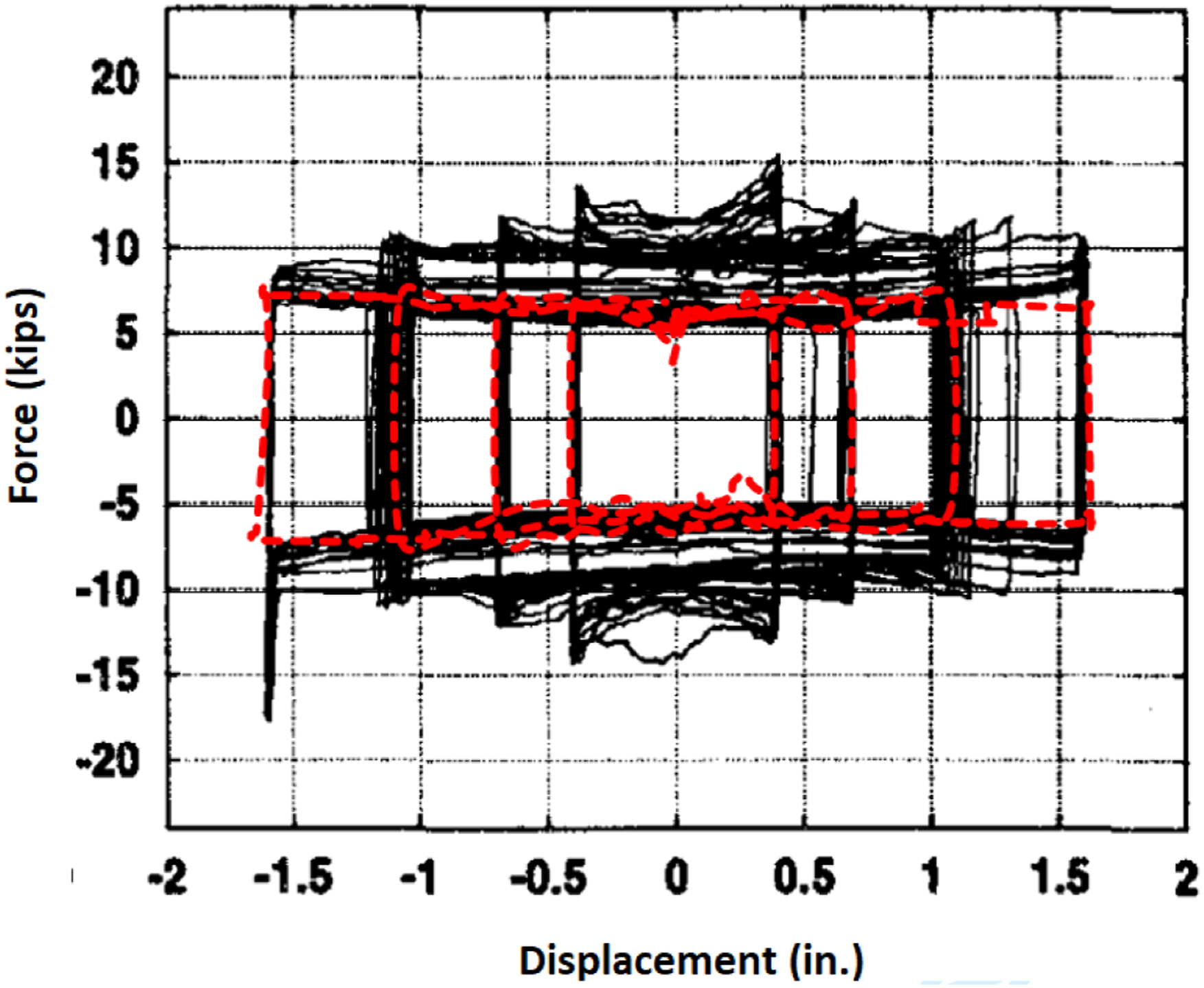
The large force spike that appears in the lower left corner of the hysteresis loop is due to bolt bearing against the deformed walls of the punched slots. This is the result of test equipment (CIT machine) limitation which allows no lateral bending in the specimens, and therefore the bolt cannot realign within the slot. This is not the case in a real structure and the spike is not to be expected.
Comparison of SEA-Steel plate shear wall with another steel plate shear wall system
The behavior of the proposed SEA-SPSW system is compared with a SPSW system studied by Wei et al. (2017). The Wei et al. system was selected for comparison because like the proposed system, the Wei et al. system is an all steel system in that the infill plate and all the boundary elements are made of steel. In addition, no stiffeners or perforations are present in either system. Moreover, for both systems the infill plate is not connected to the full length of the columns. The comparison will be made for displacement, equivalent viscous damping ratio, and cumulative energy dissipation when these systems are subject to the same loading history.
Steel plate shear wall system
The system studied experimentally and numerically by Wei et al. (2017) is shown in Figure 12. It consists of an infill steel plate (the SPSW) with dimensions h = w = 1 m connected to the boundary elements (i.e., the surrounding beams and columns) by angles and gusset plates at all four corners. The boundary elements are H sections with overall depth = 312 mm, flange width = 310 mm, web thickness = 21 mm, and flange thickness = 20 mm. Two specimens, referred to as SPSW1 and SPSW2, with similar geometrical and boundary conditions but different infill plate thicknesses (t = 2.38 and 3.2 mm) and yield strengths (210 MPa and 223 MPa) were tested. Both specimens were designed to dissipate energy via inelastic buckling of the SPSW. Steel plate shear wall system (Wei et al., 2017).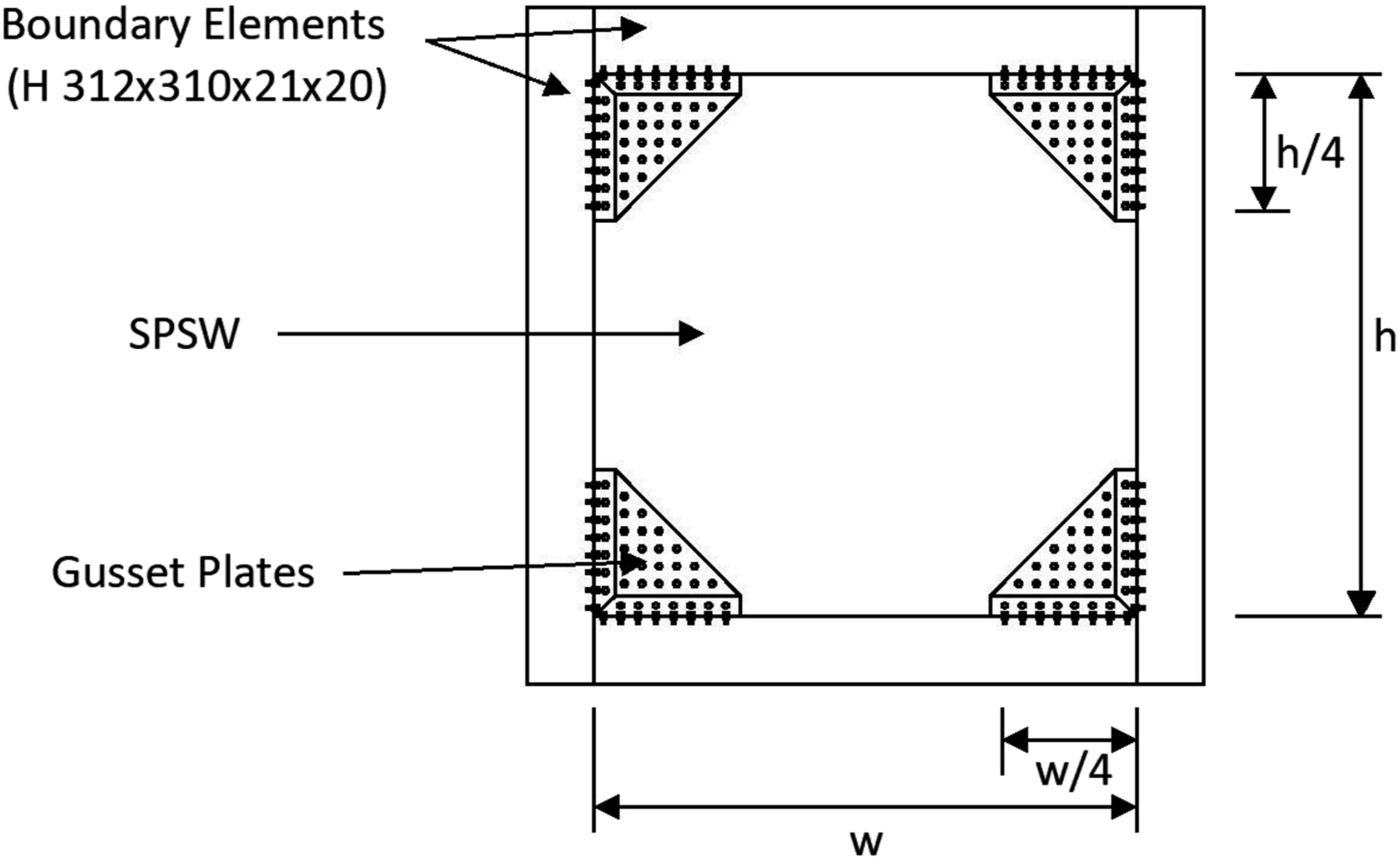
The loading protocol used is shown in Figure 13. It consists of two loading stages - force controlled followed by displacement controlled once the plate experienced yielding under V
y
. In the displacement-controlled portion of the load protocol where energy will be dissipated, the drift ratio at yield θ
y
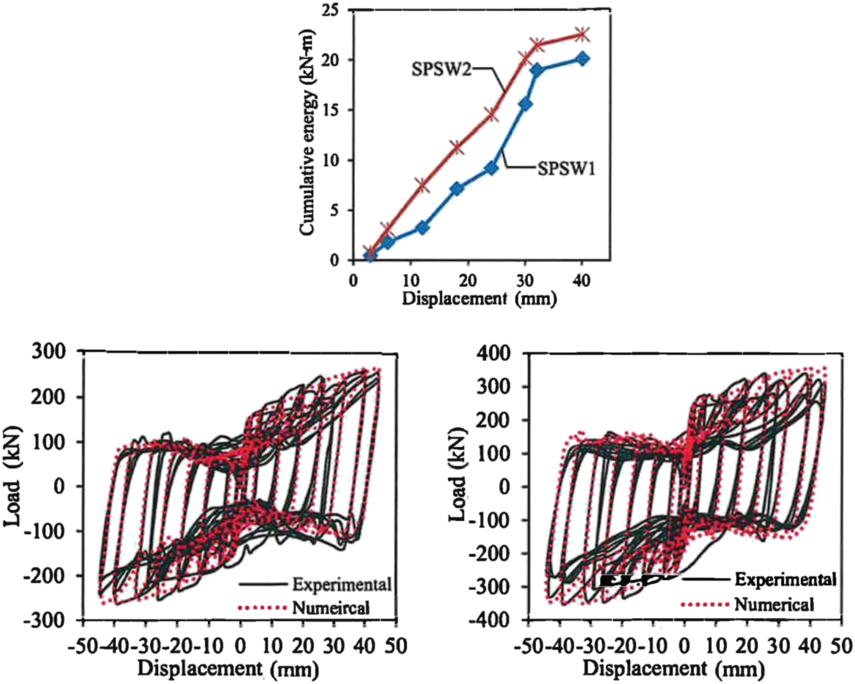
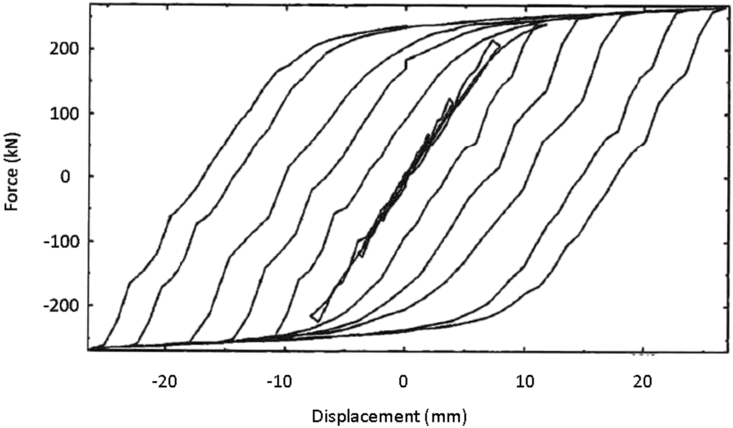
was taken as 0.3%. After completion of the tests, numerical simulations of these two SPSW systems were performed using ABAQUS software with the frame and infill plate elements modeled using reduced-integration four-node shell elements S4R. A yield strength of 210 MPa and 223 MPa were used for the SPSW1 and SPSW 2, respectively, and a yield strength of 345 MPa was used for the boundary frame elements. The ABAQUS/Explicit solver was used to perform the nonlinear cyclic analysis, and kinematic hardening rule was assumed for the material to account for the Bauschinger effect during cyclic loading. The cumulative dissipated energy and hysteresis loops obtained for the two specimens under the displacement-controlled portion of the load protocol are shown in Figure 14. The pinching of the hysteresis loops is the result of the SPSW experiencing buckling. Loading protocol used by Wei et al. (2017). Average cumulative dissipated energy (top) and hysteresis loops (bottom) obtained for the two specimens by Wei et al. (2017).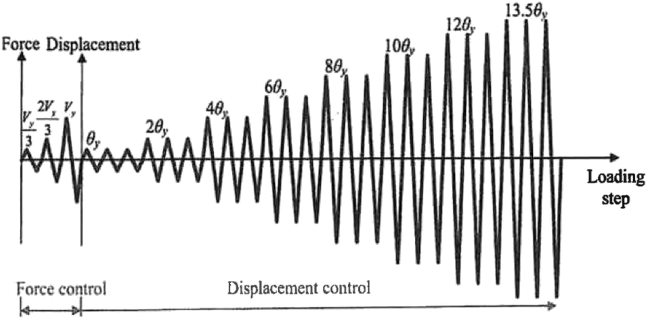
SEA-Steel plate shear wall system
The SPSW system shown in Figure 12 is now retrofitted with a SEA-SPSW depicted in Figure 5. While the same boundary elements (i.e., H 312×310×21×20) are used, the plate segments are now connected only to the beams by welds, not by angles and gusset plates at the four corners as in the initial setup. However, to simulate the effect of the angles and gusset plates, the connections of all the boundary elements are modeled as rigid. The SEA-SPSW system is to be designed to remain essentially elastic for the entire load protocol. Furthermore, the SEA-SPSW is expected to undergo negligible lateral displacement under low load levels, but slippage is allowed to occur, i.e., the friction damper will be engaged, under high load levels. Since the amount of clamping force determines the shear threshold at which slippage occurs, V slip is considered an important design parameter. The amount of clamping force affects the system’s dynamic behavior. If the clamping force is too high, yielding of the steel plates and surrounding frame elements may occur prior to initiation of sliding, which is not desirable. Hence, to achieve the above-mentioned design goal and enforce the non-sliding condition under low load levels, V slip is to be obtained based on the system’s shear capacity V c . Since the SEA-SPSW is to be designed to remain mostly elastic, V c can be calculated using equation (5). The maximum sliding shear resistance V slip is set equal to approximately two-third the steel plate shear wall’s capacity, i.e., V slip ≈ 2/3 V c . This ratio follows a similar concept used in ASCE/SEI 7-22 (2022) in which the Design Earthquake Response Spectrum is obtained by applying a factor of 2/3 to that of the risk-based Maximum Considered Earthquake (MCER) spectrum. Herein, V slip can be viewed as the design shear knowing V c as given in equation (5) is the system’s shear capacity. Once V slip is obtained, the clamping force N clamping can be calculated using the equation 0.5V slip /μ, where μ is the coefficient of friction (which for design purpose can be approximated as 0.3 for steel-to-steel contact). The factor 0.5 is introduced because friction surfaces are present on both sides of the SEA-SPSW.
The steps used to design this SEA-SPSW is summarized below. (a) Knowing the height h and width w of the opening where the infill plate will be mounted, determine the amount of cut a and d as shown in Figure 4 using the equations a ≈ 0.15×(the smaller of h and w) and d ≈ 0.42h. (b) Determine the thickness of the plate t by ensuring that h/t ≤ 100 for pinned support condition and h/t ≤ 175 for fixed support condition (see Figure 7). (c) Calculate the capacity of the plate V
c
using equation (5). Note that V
c
can be increased by increasing F
y
and/or t, if needed. (d) Determine V
slip
from the equation V
slip
≈ 2/3 V
c
. (e) Calculate the clamping force needed using the equation N
clamping
= 0.5V
slip
/μ. (f) Determine the number and size of bolts needed to provide this clamping force by dividing N
clamping
by the clamping capacity of the bolts. This clamping capacity is taken as 75% of the proof load of the bolts (https://www.engineeringtoolbox.com/us-bolts-tensile-proof-load-d_2066.html). To ensure that the clamping force is more or less uniformly distributed over the contact area, the bolts should be spaced in such a way that their center-to-center distance is between 3d
b
(where d
b
is the bolt diameter) and the smaller of 24t (where t is the thinner of the connected parts) or 300 mm. (g) Determine the slot size of the long-slotted hole using FEMA 356 (2000) story drift limit of 0.005h. This drift limit is applicable for braced frames designed to satisfy the performance level of immediate occupancy (i.e., structural components experience very little or minor damage with no observable permanent deformations). To allow for a maximum inter-story displacement of 0.005h, the slot length of the long-slotted holes should be at least equal to 0.005h+d
b
. In the US, the specified slot lengths of long-slotted holes automatically satisfy this requirement for all commonly used high strength bolts (ANSI/AISC 360-23, 2023) as long as h does not exceed 300d
b
. (h) Determine the width of the steel strips by ensuring an edge distance of about 2d
b
is maintained on both sides of the bolts. With reference to Figure 5, the width of the steel strips should therefore be at least 8d
b
. The length of the steel strips should be at least (w - 2a) to cover the entire free edge of the SEA-SPSW. To avoid heaving and to ensure the force is evenly distributed over the contact areas of the two plate segments and the steel strips when the bolts are tightened, the thickness of the steel strips should not be too small. It is recommended that it be taken as the same as or slightly larger than that of the SEA-SPSW.
Using the above procedure with F y = 250 MPa (A36 steel) and w = h = 1 m, a, d, and t are determined to be 0.15 m, 0.42 m, and 10 mm, respectively. The SEA-SPSW shear capacity V c and the shear threshold at which slippage occurs V slip are obtained as 400 kN and 267 kN, respectively. The clamping force N clamping is calculated to be 445 kN. From the tables given in (https://www.engineeringtoolbox.com/us-bolts-tensile-proof-load-d_2066.html), twelve 13-mm (½-inch) coarse thread SAE Grade 5 bolts (with a clamping capacity of 40.4 kN per bolt) placed in two rows (six on the upper and six on the lower plate segments) spaced 160 mm (which falls between 3d b = 38 mm and 24t = 240 mm) apart in the horizontal direction are to be used. Long slotted holes with width × length = 15 mm × 32 mm are used (ANSI/AISC 360-23, 2023). The sizes of the steel strips to be used are length ≈ w – 2a = 850 mm, width ≈ 8d b = 102 mm, and thickness = 10 mm.
Parameters used in the FE analysis of SEA-SPSW system.
Results and discussions
Push-Over analysis
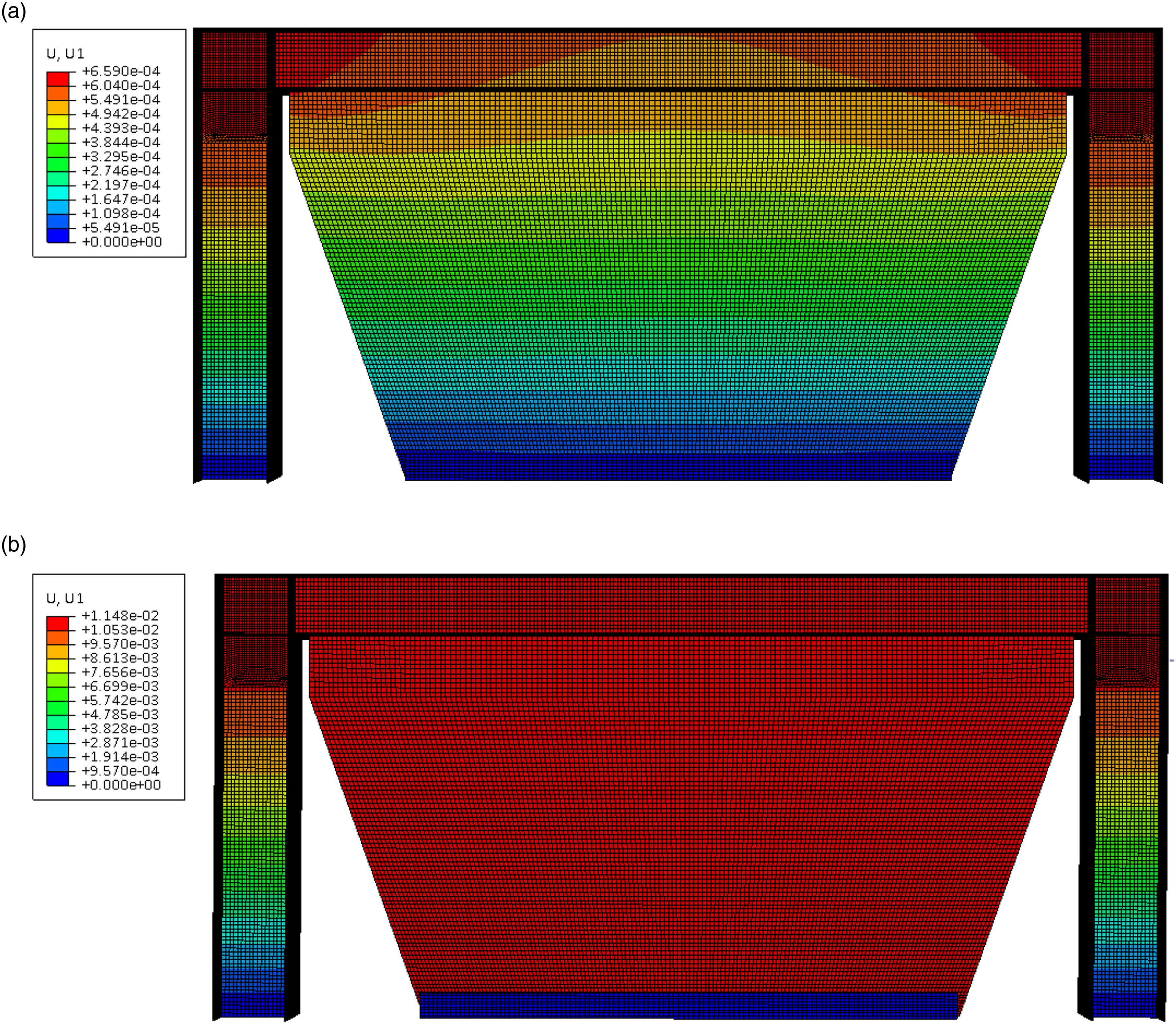
The behavior of the SEA-SPSW system was first studied using a push-over analysis. In the push-over analysis, the clamping force was first applied as a pressure load along the bottom edge of the SEA-SPSW model where the steel strips would be located. A shear force was then applied to the top left corner of the SEA-SPSW system. The von Mises stress and lateral displacement contours that correspond to V
slip
and V
c
are shown in Figures 15 and 16, respectively. It can be seen that at V
slip
, yielding does not occur in any part of the system; and at V
c
, only minimal yielding is observed at the upper corners of the SPSW and in the frame (boundary) elements near the beam-column joints. Von Mises stress distributions (Pa) under V
slip
(top) and V
c
(bottom). Lateral displacement contours (m) under V
slip
(top) and V
c
(bottom).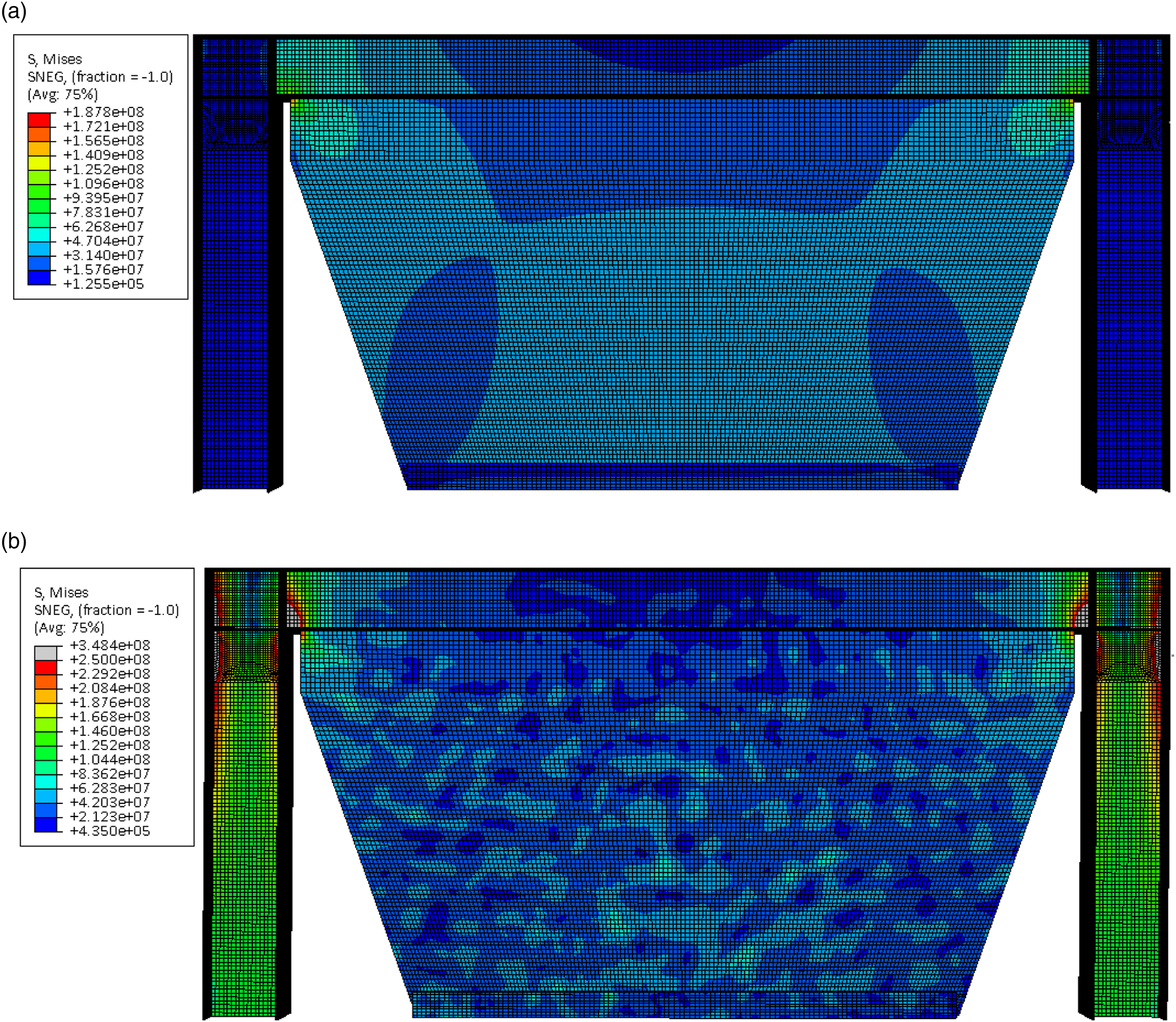
Cyclic analysis
The hysteresis loops when the SEA-SPSW system was subjected to the cyclic load protocol given in Figure 13 are shown in Figure 17. Because the geometry and thickness of the infill plate of the SEA-SPSW system is different from those of Wei, et al.’s, the drift ratio at yield θ
y
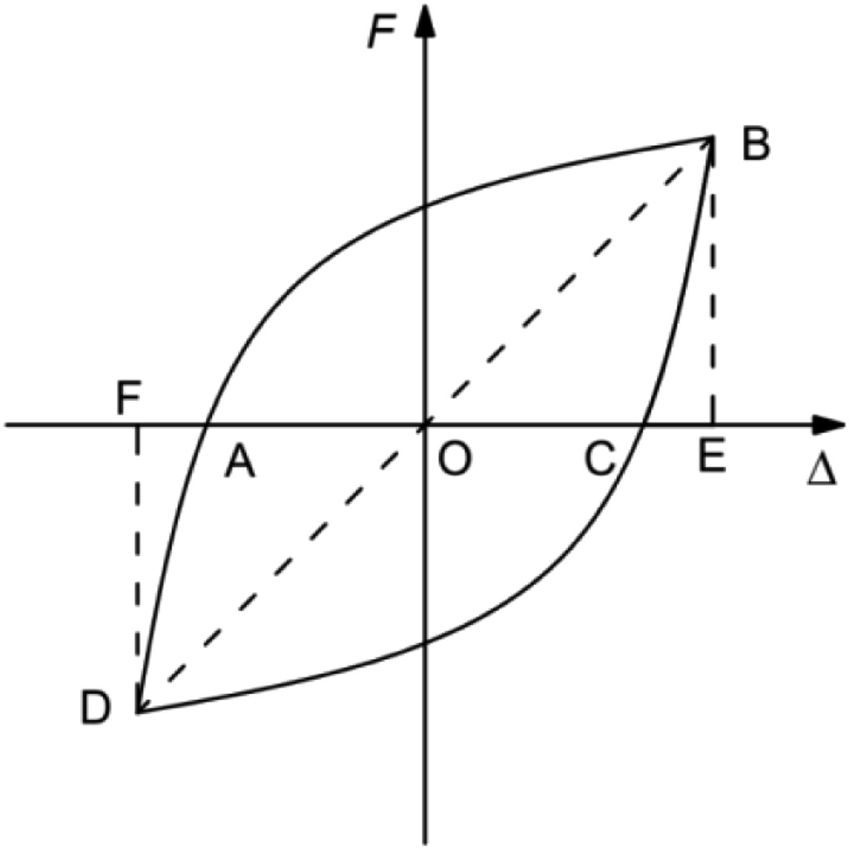
is now equal to 0.124%. The loops exhibit stable behavior (as any well-designed friction damper should) and do not show any pinching that the original SPSW system experienced. The shapes of the hysteresis loops are not rectangular as shown in Figure 8 because the boundary elements undergo deformation under the applied loads. For purpose of comparison, the equivalent viscous damping ratio ξ for the proposed SEA-SPSW system and the two SPSW systems tested by Wei et al. (2017) when they are at their maximum capacity are calculated using the equation. Hysteresis loops for the SEA-SPSW system. Calculation of equivalent viscous energy.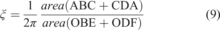
Comparison of energy dissipation
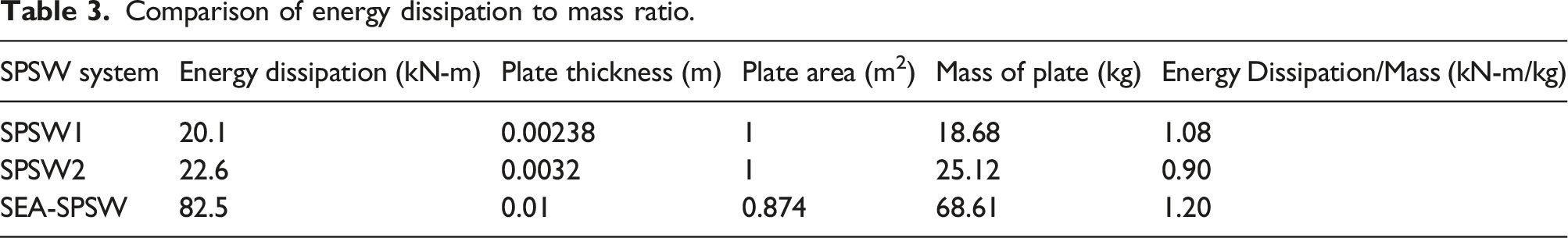
The cumulative energy dissipated by the SEA-SPSW system, obtained as the area enclosed by the hysteresis loops, is compared to the two SPSW systems reported Wei et al. (2017) in Figure 19. Since the energy dissipation mechanism of the two SPSW systems are different - inelastic buckling of the steel plate for Wei et al.’s system, but friction in the proposed SEA-SPSW system - the plate used for the SEA-SPSW system was much thicker (10 mm vs 2.38 mm and 3.2 mm) in order to preclude yielding and buckling. The SEA-SPSW is therefore heavier. In addition, given that the shapes and the areas of the plates are not the same, it is more reasonable to compare the energy dissipated per unit mass of plate for these two systems. The comparisons are given in Table 3. As can be seen, the energy dissipation to mass ratio is higher for the proposed SEA-SPSW system. It also experiences less deformations because all the structural elements (the plate and the boundary elements) remain mostly elastic. Because the proposed system does not undergo inelastic buckling to dissipate energy, it does not need to be replaced after an extreme load event. It can just be reset and is ready for reuse. Cumulative dissipated energy versus displacement plots of the SEA-SPSW system and SPSWs tested by Wei et al. (2017). Comparison of energy dissipation to mass ratio.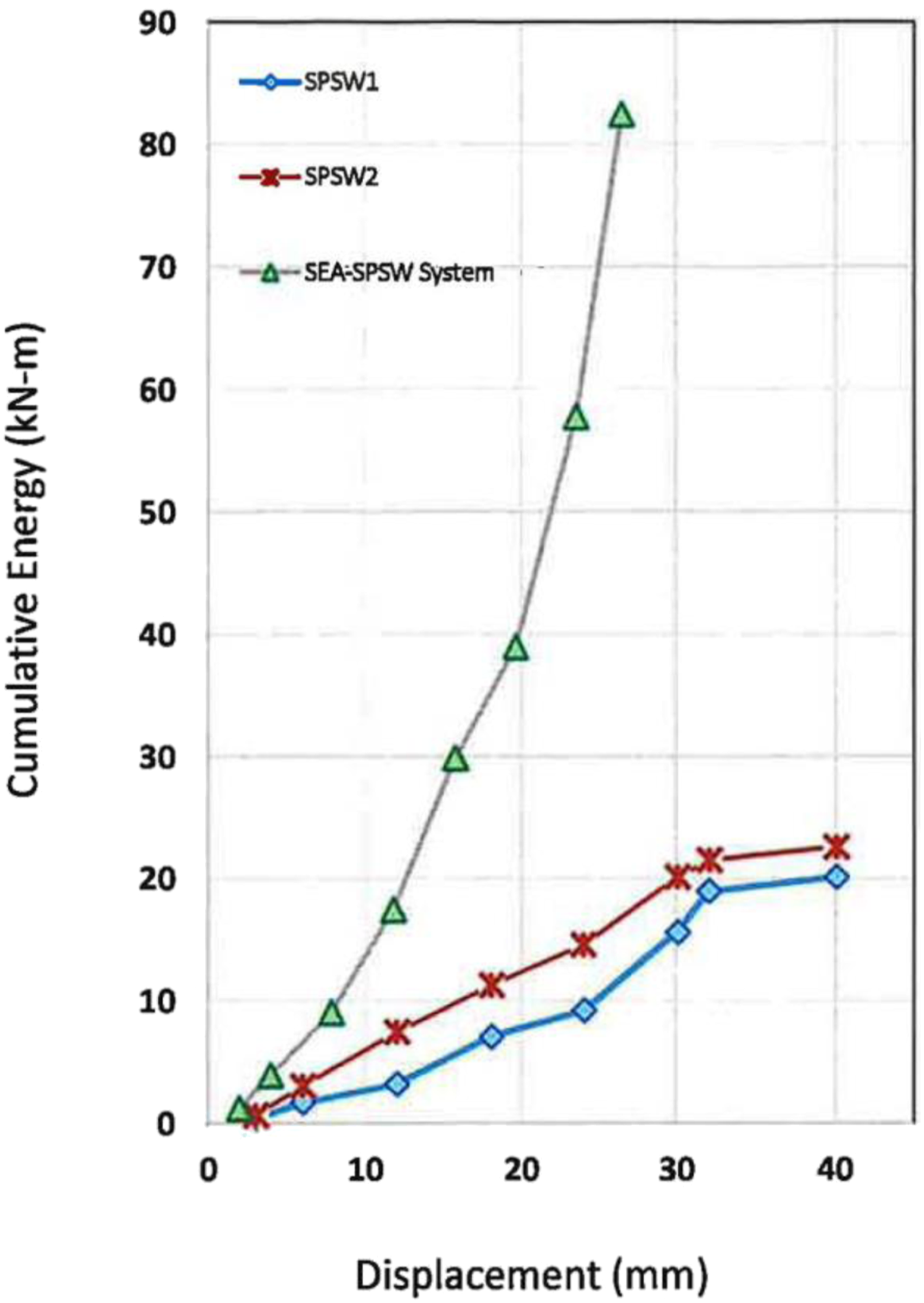
Summary
Under extreme load conditions, conventional steel plate shear walls (SPSWs) are often designed to undergo yielding and buckling to dissipate energy. This makes reparation and replacement difficult and costly. In this paper, a new SPSW system referred to as Segmented Energy Absorbing SPSW (SEA-SPSW) system was introduced. Since the proposed system relies on friction to dissipation energy, the steel plate as well as all the boundary elements can be designed to remain essentially elastic. If properly designed, the system should not experience any observable damage after an extreme load event. It can be reset and reused for future extreme load events.
The proposed system consists of two trapezoidal shaped steel plates connected to the top and bottom beams and joined together at the free edges by two steel strips held together using high strength bolts through long-slotted holes. Because the plates are not directly connected to the columns, the high force demand on the columns that has been observed for some conventional SPSW systems which rely on tension field action is avoided. Under normal load conditions, the proposed system acts as a regular shear wall, providing strength and stiffness to the building; but under extreme load conditions, the two segmented plates will slide relative to each other between the steel strips and dissipation energy through friction.
Equations to determine the optimal geometries of the trapezoidal shaped segmented plates including plate thickness needed to preclude plate buckling are provided. Also given are equations to determine the yield capacity and slip load of the steel plate, as well as a procedure to design the system. A finite element model was developed and finite element analysis was performed to assess the hysteretic behavior and energy dissipation capacity of the proposed system. The results were then compared to those of an all steel conventional SPSW system which bears some similar characteristics to the proposed system.
Being a friction damper, the proposed system exhibits stable hysteresis; and because buckling is precluded, the hysteresis does not experience any pinching effect. As a result, the proposed system is capable of providing a desirable equivalent damping ratio as well as a favorable cumulative energy dissipation to mass ratio.
Footnotes
Declaration of Conflicting Interests
The author(s) declared no potential conflicts of interest with respect to the research, authorship, and/or publication of this article.
Funding
The author(s) received no financial support for the research, authorship, and/or publication of this article.